EP1925199A1 - Mobile dispensing device for food pellets, in particular for dried food pellets and for dog food - Google Patents
Mobile dispensing device for food pellets, in particular for dried food pellets and for dog food Download PDFInfo
- Publication number
- EP1925199A1 EP1925199A1 EP06024431A EP06024431A EP1925199A1 EP 1925199 A1 EP1925199 A1 EP 1925199A1 EP 06024431 A EP06024431 A EP 06024431A EP 06024431 A EP06024431 A EP 06024431A EP 1925199 A1 EP1925199 A1 EP 1925199A1
- Authority
- EP
- European Patent Office
- Prior art keywords
- food
- housing part
- housing
- ejection
- magazine
- Prior art date
- Legal status (The legal status is an assumption and is not a legal conclusion. Google has not performed a legal analysis and makes no representation as to the accuracy of the status listed.)
- Granted
Links
- 235000013305 food Nutrition 0.000 title claims description 52
- 239000008188 pellet Substances 0.000 title 2
- 235000013324 preserved food Nutrition 0.000 title 1
- 238000004146 energy storage Methods 0.000 claims description 13
- 230000003213 activating effect Effects 0.000 claims description 2
- 230000001133 acceleration Effects 0.000 description 13
- 230000007246 mechanism Effects 0.000 description 11
- 230000004913 activation Effects 0.000 description 3
- 230000006399 behavior Effects 0.000 description 3
- 230000000694 effects Effects 0.000 description 3
- 238000010276 construction Methods 0.000 description 2
- 230000005484 gravity Effects 0.000 description 2
- 239000000463 material Substances 0.000 description 2
- 238000000034 method Methods 0.000 description 2
- 239000010828 animal waste Substances 0.000 description 1
- 239000003086 colorant Substances 0.000 description 1
- 238000004040 coloring Methods 0.000 description 1
- 230000001419 dependent effect Effects 0.000 description 1
- 238000010304 firing Methods 0.000 description 1
- 210000000245 forearm Anatomy 0.000 description 1
- 239000004519 grease Substances 0.000 description 1
- 239000012535 impurity Substances 0.000 description 1
- 239000002184 metal Substances 0.000 description 1
- 238000005192 partition Methods 0.000 description 1
- 230000036316 preload Effects 0.000 description 1
- 230000004043 responsiveness Effects 0.000 description 1
Images


Classifications
-
- A—HUMAN NECESSITIES
- A01—AGRICULTURE; FORESTRY; ANIMAL HUSBANDRY; HUNTING; TRAPPING; FISHING
- A01K—ANIMAL HUSBANDRY; AVICULTURE; APICULTURE; PISCICULTURE; FISHING; REARING OR BREEDING ANIMALS, NOT OTHERWISE PROVIDED FOR; NEW BREEDS OF ANIMALS
- A01K5/00—Feeding devices for stock or game ; Feeding wagons; Feeding stacks
- A01K5/01—Feed troughs; Feed pails
- A01K5/0114—Pet food dispensers; Pet food trays
-
- A—HUMAN NECESSITIES
- A01—AGRICULTURE; FORESTRY; ANIMAL HUSBANDRY; HUNTING; TRAPPING; FISHING
- A01K—ANIMAL HUSBANDRY; AVICULTURE; APICULTURE; PISCICULTURE; FISHING; REARING OR BREEDING ANIMALS, NOT OTHERWISE PROVIDED FOR; NEW BREEDS OF ANIMALS
- A01K5/00—Feeding devices for stock or game ; Feeding wagons; Feeding stacks
- A01K5/02—Automatic devices
- A01K5/0275—Automatic devices with mechanisms for delivery of measured doses
Definitions
- the present invention relates to a mobile dispenser for food pieces, in particular for dry feed or for dog food, with the features of independent claim 1.
- Dog owners therefore usually have rewards in the form of dry food pieces (so-called "treats") to be able to give the dog at any time a piece, if this makes sense for educational reasons.
- These "treats” or dry feed pieces are administered to the dog individually in positive behaviors. Since these food pieces are generally made of animal waste products and therefore are accordingly unhygienic, the dog owner contaminates the hands when administering. During walks, there is also generally no way to clean your hands at any time.
- Another problem is that the food pieces are cumbersome stored in bags, plastic bags o. ⁇ . And transported. On the one hand, this is cumbersome and, on the other hand, it pollutes the pockets with grease and other impurities.
- the storage in clothes, for example in the pockets, is unhygienic and soiled the clothes. Often taking out the food pieces takes too long to reward the dog at the right moment of education. If too long a time passes between the rewarding behavior of the dog and the administration of the food piece, the education effect threatens to be lost because the dog no longer knows why he is rewarded.
- a common solution to some of the problems outlined is the storage of the food pieces in closed boxes, for example, small plastic boxes with closable lid or small metal cans, which can be washed out after each use and refilled.
- closed boxes for example, small plastic boxes with closable lid or small metal cans, which can be washed out after each use and refilled.
- the removal of the food pieces is cumbersome and often takes too long for the desired educational effect.
- the dry food should be removable, without the user gets his hands dirty.
- a mobile device for dispensing pieces of food, in particular for dispensing dry food or dog food, comprises a magazine for storing a plurality of food pieces and a dispensing device coupled therewith for the occasional dispensing of food pieces after respective manual actuation by a user.
- the dispensing device has a device for accelerated dispensing or accelerated ejection of individual food pieces.
- the accelerated ejection of treats forms a game component for the dog, which combines a reward of the dog not only with a Futter Georgia Pacific Culture Culture, but additionally with the challenge and satisfaction of the play instinct of the dog. Just catching an ejected food piece and thus the responsiveness of the dog can be trained in this way and each rewarded immediately. If catching ejected food bits is trained and brings the dog pleasure, it can henceforth be used as a reward for other positive behaviors.
- the dispenser of the present invention includes an energy store coupled to an ejector.
- the energy storage of the dispenser may, for example, comprise at least one tension spring.
- This can be, for example, at least one coil spring or at least one leg spring.
- the energy storage or the tension spring, coil spring or leg spring is preferably activated or tensioned by manual operation by the user.
- the ejection device according to the invention can preferably be manually set by a user in an activated state.
- a displaceable or rotatable clamping lever for activating the energy storage eg.
- tension of the at least one tension spring can be arranged on the housing.
- a single food piece can be brought into an ejection position, for example.
- a single food piece can be conveyed from the magazine into the ejection device.
- a slider in its end position releases a shaft through which the treats from the magazine can fall into a chamber or an acceleration shaft of the ejection device.
- the device is held, for example, via a mechanical locking mechanism, which, for example, the displaceable or rotatable clamping lever in an end position, held in this activated state, with energy-laden energy storage and in-position treats.
- the device according to the invention is ready in this state, the treats expedited or not accelerated spend.
- the user may simply tilt the device such that the food piece falls out of the dispenser due to gravity.
- the user preferably again manually, activate the ejection device.
- Activation can be effected by manual actuation, for example, of a release lever arranged on the housing or of a release button which releases the latching mechanism and thereby releases the energy from the energy store, for example by releasing the tensioning spring.
- this activation of the ejection device preferably only a single piece of food is thrown out of the dispensing device.
- the ejection device can be a slider, an acceleration slide or the like for accelerated delivery of one in the chamber or in the acceleration shaft located lining piece from an ejection opening of the ejection device.
- the slider or acceleration slide is for this purpose coupled to the energy storage or the tension spring and the release button or lever.
- the release button or lever releases the latching mechanism that activates the energy storage or keeps the tension spring tensioned, and the energy released is used to move the acceleration slide or slider. This speeds up the tidbit put in place and pushes it out of the facility.
- the release button or lever can be arranged at any position on the housing; According to a preferred embodiment, it is arranged centrally.
- the ejection speed at which the food piece leaves the ejector, and thus the possible throw is variable, preferably, by the energy storage is variably adjustable, for example.
- a variably adjustable bias of the tension spring For example.
- the locking mechanism for locking the displaceable or rotatable clamping lever can engage in different positions, each having a different bias of the tension spring result.
- the position of the tension spring can be changed so that it is brought in each case the same position of the locking mechanism in different, dependent on its own position bias.
- the device of the present invention is preferably composed of several components.
- the device comprises at least two housing parts.
- a first housing part of the device preferably comprises the magazine, which serves as a storage container for treats.
- This housing section is preferably open, so that the magazine can be refilled by the user.
- a coupled to the first housing part second housing part comprises the dispenser.
- This second housing section is closed and serves as a mechanical floor assembly.
- the first housing part is placed on the second housing part and fastened, for example. Via a snap or locking connection.
- the first and the second housing part are preferably rotatable connected to each other, so that the magazine rotatably seated on the dispenser.
- the first housing part may have a hole into which a pin o. ⁇ .
- the second housing part is rotatably inserted by means of a snap connection.
- the first housing part could, for example, have a circumferential annular groove into which an annular web of the second housing part can be latched. Ring groove and bridge can also be arranged climatic reverse. Further rotatable connections are conceivable; the invention is not limited in this regard.
- the magazine preferably has a plurality of separated housing segments, each of which serves to receive at least one piece of food.
- the separated housing segments each serve to receive exactly one Futter Swisschens.
- the first housing portion may be open at the bottom, so that it has a hood shape largely. It can be placed on the second housing part in such a way that the upper side of the second housing part covers the opening of the first housing part and closes it in such a way that food pieces inserted in the housing segments can not fall out.
- the first housing portion may comprise a bottom plate which is provided with an opening, which preferably corresponds in size and shape with the size and shape of a housing segment.
- the magazine with the housing segments is preferably rotatably mounted on this base plate. Such a first housing part is placed over its bottom plate on the second housing part and, for example, locked.
- the opening in the bottom plate is in this case preferably positioned above a chamber or above the acceleration shaft of the dispensing or ejecting device.
- the rotation of the two housing parts against each other is preferably carried out stepwise or rasterized.
- a rotation of the first housing part against the second by a latching step is preferably in each case a housing segment of the magazine and thus a present in this housing segment Futter Glachen over a chamber or positioned above the acceleration shaft of the ejection device.
- the thus positioned housing segment of the magazine is then released relative to the ejection device, for example by a slider, which is for example. Coupled with the clamping lever, an opening at the top of the second housing part or a shaft releases through which the Futterzhou can fall through. In this case, the food piece is conveyed into the chamber or into the acceleration shaft of the ejection device.
- the rotation of the first housing part or magazine is preferably carried out manually.
- an automatic promotion may be provided.
- a latching hook which engages during the process of tension of the tension spring in the first housing part and this during the clamping operation rotates one step further, so that a new housing segment comes to rest on the chamber or on the acceleration shaft.
- Other mechanisms are also conceivable.
- An automatic promotion of the magazine avoids that the rotation of the magazine is forgotten, and due to a not in-position food piece a supposed firing does not take place. Such an unsuccessful launch has an undesirable effect on the dog's education and should therefore be avoided.
- the housing parts are preferably separable from each other and each separately cleanable.
- At least the first housing part of the device, which has the magazine, is preferably made of washable and dishwasher-safe material, in particular made of plastic. It is preferably at least partially transparent, so that at any time the level of the magazine can be tested. A coloring in different colors is also possible and adapt to the customer's wishes.
- the second housing part, which comprises the ejection device may in this case, for example, be made opaque in the same color.
- the first housing part or the magazine arranged thereon may be formed as a disposable part, which is removed after emptying and replaced by a new magazine.
- a disposable magazine may, for example, have a peelable film closure, which hygienically seals the treats contained therein and is removed only immediately before placing on the second housing part.
- entrainment of additional treats is particularly simplified.
- a first housing part which has the magazine, be commercially available individually, so that several, each self-filled and refillable magazines can be carried when an increased number of treats is needed.
- the device according to the invention may have a holder for a replacement magazine, whereby the entrainment of additional treats is particularly facilitated.
- the inventive device for dispensing food pieces is preferably designed to be handy in shape and size and thus at any time man portable.
- the size of the standard device is adapted for easy use, but for different purposes, the size can be variably adjusted. For example.
- a device that is purposefully used in dog dressage at the dressage grounds may be larger than a device that a dog owner carries along during his daily walk.
- the former can also reach a size that is no longer portable but preferably used stationary.
- the device according to the invention can be equipped with a carrying device, for example with a buckle for fastening the device to a belt or trouser hem, a carrying strap or a strap for attachment to the forearm.
- a carrying device for example with a buckle for fastening the device to a belt or trouser hem, a carrying strap or a strap for attachment to the forearm.
- the use of a special carrying bag, which in turn has a carrying or holding device, may be advantageous.
- a small embodiment of the invention can also be equipped, for example, with a snap-hook or the like, so that it can be fastened to a belt loop or to a backpack outer belt or the like.
- the device according to the invention can have an acoustic training aid or an acoustic lock signal, for example an integrated clicker for clicker training.
- a clicker may, for example, be arranged independently of the release button on the housing, so that the triggering process and the acoustic signal are independent of each other.
- the clicker is located in the vicinity of the release button or lying opposite to it, to accomplish easy handling.
- the clicker in the Trigger button is integrated, so that each release is coupled with an acoustic signal.
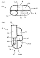
- FIG. 1 shows a schematic plan view of a first housing part 20 of a device 10 according to the invention.
- the first housing part 20 comprises the magazine 21, which serves to store a plurality of food pieces (not shown).
- the first housing part 20 has a plurality of respectively closed housing segments 22 which each serve to receive less or preferably exactly one lining piece.
- the first housing part 20 is hood-shaped; it has no bottom plate and is downwardly or to the side, which faces the second housing part 30 in the assembled state (see Figures 3 to 7), open. In this hood run dividing walls 23, which separate the housing segments 22 from each other.
- the first housing part 20 has a centrally disposed portion 24 for rotatable attachment to a second housing part 30.
- the attachment portion 24 is in the illustrated case a hole into which a pin o. ⁇ .
- Of the second housing part 30 is rotatably inserted by means of a snap connection.
- the side view of the first housing part 20 shown in Figure 2 illustrates the structure of the magazine designed as described 21 for storing Futter Nursingchen, in particular the hood-like shape and the central hole 24 for rotatably mounting the first housing part 20 to a corresponding structure of the second housing part 30 can be seen ,
- the magazine 21 as shown in Figures 1 and 2 can be filled by the user with food pieces and refillable at any time, since it is removable from the second housing part 30 and thereby open. It is made of a transparent and dishwasher-safe material, preferably a high-quality plastic, so that a hygienic storage of food pieces is possible and the level can be checked at any time.
- FIG. 3 illustrates the construction of a second housing part 30 of a device 10 according to the invention, which device comprises the delivery device, which in the example shown has an ejection device 40.
- the ejection device 40 is in the representation of Figure 3 in a relaxed position.
- the dispensing device 30 is a closed housing part with a mounting portion 36 for rotatably mounting the first housing part 20 or magazine 21.
- the mounting portion 36 may, for example, a cylinder portion or a pin o.ä. have, which corresponds in size and shape with the central hole 24 of the first housing part 20, so that the first housing part 20 with its hole portion 24 on the cylinder or pin portion 36 of the second housing part 30th can be plugged.
- latching, snap or other support structures may be present.
- the dispensing device 30 comprises a chamber or an output shaft 42, in the region of which an opening 34 is arranged on the upper side of the housing part 30. Through the opening 34, in each case the contents of a housing segment 22 of the magazine 21 positioned above it, preferably exactly one lining piece, can fall into the chamber or the output shaft 42, provided that the opening 34 is released.
- the chamber or the shaft 42 has an outlet opening 32 through which a chuck piece conveyed into the chamber or the shaft 42 can be discharged to the outside. In the illustrated embodiment of the invention, this delivery can optionally be accelerated or not accelerated.
- the ejection device 40 comprises: an actuating element 54 with a guide pin 52, on which a spiral spring 48 is attached at least in sections, which serves as an energy store; a slider 44 having a guide sleeve 50 which surrounds the coil spring 48 at least in sections; a tensioning lever 46, by means of which the slider 44 is manually movable, whereby the coil spring 48 is compressed and thus placed under tension; a detent mechanism (not shown) which detects the slider 44 in a position in which the coil spring 48 is under tension and presses against the slider 44 (activated state of Fig.
- a release button 58 (visible in Figures 5 and 6) which releases the latching mechanism and thereby releases a relaxation of the coil spring 48 with simultaneous movement of the slider 44 within and along the output shaft 42; an abutment means 60 which defines a maximum movement of the slider 44 and which counteracts the spring tension.
- the opening 34 is released by the manually carried out via the clamping lever 46 movement of the slider 44 in its locking position, since in this movement, the components of the ejector 40, which obscure the opening 34, namely coil spring 48, guide sleeve 50 and the slide 44 themselves, beyond the opening 34 out and next to these are pushed.
- the activated position thus obtained which is shown in FIG. 4
- a food piece can be positioned from above the opening 34 Housing segment 22 of the magazine 21 fall into the underlying chamber or the output shaft 42.
- the rotational movement of the magazine 21 is preferably rastered, so that a rotation about a latching step in each case an exact positioning of a housing segment 22 has over the opening 34 to the episode.
- a chuck piece conveyed in the described manner into the discharge chute 42 can now be simply outwardly discharged through the discharge port 32 by tilting the entire device 10 such that the chuck piece falls out by gravity.
- the trigger button 58 may be actuated, resulting in a rapid movement of the slider 44, which now serves as an acceleration slide and accelerates the liner over the outlet opening 32 out of the device 10.
- FIGS. 5 and 6 each show, in schematic sectional views from different directions, the construction of the device 10 according to the invention in the activated state, as described with reference to FIG.
- the slide or acceleration slide 44 occupies the entire height of the output shaft 42 and thus can also carry small bits of food or crumbled pieces of food to the outside.
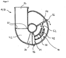
- FIG. 7 again shows a device 10 according to the invention in the activated state, wherein a lower bias of the spring 48 is set by means of the adjusting element 54.
- the actuator 54 can be solved by means of a latching mechanism 56, moved in the direction of the arrow and locked in another position again.
- a changed spring preload has a changed ejection speed and thus a changed throw range.
- the illustrated device 10 is so handy in terms of shape, size and weight that it is always worn on the man. It is therefore also suitable for carrying on walks. Dog owners no longer have to take treats in an unhygienic and impractical manner in carrying bags or even jackets or trouser pockets, but instead have a hygienic storage box which, to the same extent, makes it easy to remove individual food pieces as well as being a practical gaming device and an excellent educational aid.
- the invention is expressly not limited to the above embodiment. Both the shape and the tensioning and ejecting mechanism of the device may be different from those described. In particular, other energy storage means than the coil spring shown can be used and the housing parts can be rotatably connected to each other in other than the manner shown.
- the embodiment shown is only to be understood as an example and does not limit the invention.
Landscapes
- Life Sciences & Earth Sciences (AREA)
- Environmental Sciences (AREA)
- Birds (AREA)
- Animal Husbandry (AREA)
- Biodiversity & Conservation Biology (AREA)
- Feeding And Watering For Cattle Raising And Animal Husbandry (AREA)
- Confectionery (AREA)
- General Preparation And Processing Of Foods (AREA)
- Vending Machines For Individual Products (AREA)
- Frying-Pans Or Fryers (AREA)
Abstract
Description
Die vorliegende Erfindung betrifft eine mobile Abgabevorrichtung für Futterstücke, insbesondere für Trockenfutterstücke bzw. für Hundefutter, mit den Merkmalen des unabhängigen Anspruchs 1.The present invention relates to a mobile dispenser for food pieces, in particular for dry feed or for dog food, with the features of independent claim 1.
Es ist bekannt, dass nahezu jeder Hund mit Hilfe von Belohnungen trainiert bzw. erzogen werden kann. Hundehalter haben deshalb normalerweise Belohnungen in Form von Trockenfutterstücken (sog. "Leckerlies") bei sich, um dem Hund jederzeit ein Stück geben zu können, wenn dies aus erzieherischen Gründen sinnvoll erscheint. Diese "Leckerlies" bzw. Trockenfutterstücke werden dem Hund bei positiven Verhaltensweisen einzeln verabreicht. Da diese Futterstücke im Allgemeinen aus tierischen Abfallprodukten hergestellt und daher entsprechend unhygienisch sind, verschmutzt sich der Hundebesitzer beim Verabreichen die Hände. Bei Spaziergängen besteht zudem im Allgemeinen keine Möglichkeit, die Hände jederzeit zu reinigen.It is known that almost every dog can be trained or educated with the help of rewards. Dog owners therefore usually have rewards in the form of dry food pieces (so-called "treats") to be able to give the dog at any time a piece, if this makes sense for educational reasons. These "treats" or dry feed pieces are administered to the dog individually in positive behaviors. Since these food pieces are generally made of animal waste products and therefore are accordingly unhygienic, the dog owner contaminates the hands when administering. During walks, there is also generally no way to clean your hands at any time.
Ein weiteres Problem besteht darin, dass die Futterstücke umständlich in Taschen, Plastiktüten o. ä. aufbewahrt und transportiert werden. Dies ist einerseits umständlich und verschmutzt andererseits die Taschen mit Fett und anderen Verunreinigungen. Das Aufbewahren in der Kleidung, bspw. in den Hosentaschen, ist unhygienisch und verschmutzt die Kleidung. Oft dauert das Herausnehmen der Futterstücke zu lange, um den Hund im richtigen Moment der Erziehung zu belohnen. Wenn zwischen dem zu belohnenden Verhalten des Hundes und der Verabreichung des Futterstückes eine zu lange Zeit vergeht, droht der Erziehungseffekt verloren zu gehen, da der Hund nicht mehr weiß, warum er belohnt wird.Another problem is that the food pieces are cumbersome stored in bags, plastic bags o. Ä. And transported. On the one hand, this is cumbersome and, on the other hand, it pollutes the pockets with grease and other impurities. The storage in clothes, for example in the pockets, is unhygienic and soiled the clothes. Often taking out the food pieces takes too long to reward the dog at the right moment of education. If too long a time passes between the rewarding behavior of the dog and the administration of the food piece, the education effect threatens to be lost because the dog no longer knows why he is rewarded.
Eine häufige Lösung für manche der skizzierten Probleme stellt die Aufbewahrung der Futterstücke in geschlossenen Boxen dar, bspw. kleinen Kunststoffboxen mit verschließbarem Deckel oder kleinen Metallbüchsen, die jeweils nach ihrem Gebrauch ausgewaschen und neu befüllt werden können. Es bleibt hierbei jedoch weiterhin der Nachteil bestehen, dass das Herausnehmen der Futterstücke umständlich ist und für den gewünschten Erziehungseffekt oftmals zu lange Zeit in Anspruch nimmt.A common solution to some of the problems outlined is the storage of the food pieces in closed boxes, for example, small plastic boxes with closable lid or small metal cans, which can be washed out after each use and refilled. However, it still remains the disadvantage that the removal of the food pieces is cumbersome and often takes too long for the desired educational effect.
Aus dem Stand der Technik sind Futternäpfe und Futterausgabevorrichtungen, sog. Spender, in zahlreichen Varianten bekannt, so bspw. aus
Ein vorrangiges Ziel der Erfindung besteht demnach darin, eine mobile und leicht handhabbare Vorrichtung zur Verfügung zu stellen, mit der einem Hund Trockenfutter verabreicht werden kann. Vorzugsweise soll das Trockenfutter entnehmbar sein, ohne dass sich der Benutzer dabei die Hände verschmutzt.Accordingly, it is a primary object of the invention to provide a mobile and easy to handle device for administering dry dog food to a dog. Preferably, the dry food should be removable, without the user gets his hands dirty.
Diese Ziele der Erfindung werden mit dem Gegenstand des unabhängigen Anspruchs erreicht. Eine erfindungsgemäße mobile Vorrichtung zur Abgabe von Futterstücken, insbesondere zur Abgabe von Trockenfutter bzw. von Hundefutter, umfasst ein Magazin zur Aufbewahrung mehrerer Futterstücke sowie eine damit gekoppelte Abgabeeinrichtung zur vereinzelten Abgabe von Futterstücken nach jeweiliger manueller Betätigung durch einen Benutzer.These objects of the invention are achieved with the subject matter of the independent claim. A mobile device according to the invention for dispensing pieces of food, in particular for dispensing dry food or dog food, comprises a magazine for storing a plurality of food pieces and a dispensing device coupled therewith for the occasional dispensing of food pieces after respective manual actuation by a user.
Gemäß einer bevorzugten Ausführungsform der Erfindung weist die Abgabeeinrichtung eine Einrichtung zur beschleunigten Ausgabe bzw. zum beschleunigten Auswurf einzelner Futterstücke auf. Insbesondere sind hierbei Trockenfutterstücke gemeint, die dem Hund zur Belohnung gereicht werden und die auch als "Leckerlies" bezeichnet werden. Der beschleunigte Auswurf von Leckerlies bildet eine Spielkomponente für den Hund, die eine Belohnung des Hundes nicht nur mit einem Futterstückchen, sondern zusätzlich mit der Herausforderung und Befriedigung des Spieltriebs des Hundes verbindet. Allein das Fangen eines ausgeworfenen Futterstückchens und damit das Reaktionsvermögen des Hundes kann auf diese Weise trainiert und jeweils sofort belohnt werden. Ist das Fangen ausgeworfener Futterstückchen antrainiert und bringt es dem Hund Freude, so kann es fortan als Belohnung für andere positive Verhaltensweisen eingesetzt werden.According to a preferred embodiment of the invention, the dispensing device has a device for accelerated dispensing or accelerated ejection of individual food pieces. In particular, this means dry feeds that are given to the dog as a reward and are also referred to as "treats". The accelerated ejection of treats forms a game component for the dog, which combines a reward of the dog not only with a Futterstückstück, but additionally with the challenge and satisfaction of the play instinct of the dog. Just catching an ejected food piece and thus the responsiveness of the dog can be trained in this way and each rewarded immediately. If catching ejected food bits is trained and brings the dog pleasure, it can henceforth be used as a reward for other positive behaviors.
Vorzugsweise, jedoch nicht zwingend vorgeschrieben, umfasst die Abgabeeinrichtung der vorliegenden Erfindung einen Energiespeicher, der mit einer Auswurfeinrichtung gekoppelt ist. Dieser ermöglicht einen beschleunigten Auswurf bzw. Ausstoß eines Futterstückchens. Der Energiespeicher der Abgabeeinrichtung kann bspw. wenigstens eine Spannfeder umfassen. Dies kann bspw. wenigstens eine Spiralfeder oder wenigstens eine Schenkelfeder sein. Der Energiespeicher bzw. die Spannfeder, Spiralfeder oder Schenkelfeder ist bevorzugt durch manuelle Betätigung durch den Benutzer aktivierbar bzw. spannbar.Preferably, but not necessarily, the dispenser of the present invention includes an energy store coupled to an ejector. This allows an accelerated ejection or ejection of a Futterstückchens. The energy storage of the dispenser may, for example, comprise at least one tension spring. This can be, for example, at least one coil spring or at least one leg spring. The energy storage or the tension spring, coil spring or leg spring is preferably activated or tensioned by manual operation by the user.
Die Auswurfeinrichtung kann erfindungsgemäß bevorzugt manuell durch einen Benutzer in einen aktivierten Zustand versetzt werden. Hierzu kann am Gehäuse ein verschiebbarer bzw. verdrehbarer Spannhebel zur Aktivierung des Energiespeichers, bspw. zur Spannung der wenigstens einen Spannfeder, angeordnet sein.The ejection device according to the invention can preferably be manually set by a user in an activated state. For this purpose, a displaceable or rotatable clamping lever for activating the energy storage, eg. For tension of the at least one tension spring can be arranged on the housing.
Gleichzeitig mit dieser Aktivierung des Energiespeichers kann ein einzelnes Futterstückchen in eine Auswurfposition gebracht werden, bspw. kann ein einzelnes Futterstück aus dem Magazin in die Auswurfeinrichtung gefördert werden.Simultaneously with this activation of the energy storage device, a single food piece can be brought into an ejection position, for example. A single food piece can be conveyed from the magazine into the ejection device.
Hierzu gibt bspw. ein Schieber in seiner Endposition einen Schacht frei, durch welchen die Leckerlies von dem Magazin in eine Kammer bzw. einen Beschleunigungsschacht der Auswurfeinrichtung fallen können.For this purpose, for example, a slider in its end position releases a shaft through which the treats from the magazine can fall into a chamber or an acceleration shaft of the ejection device.
Die Einrichtung wird bspw. über einen mechanischen Rastmechanismus, welcher bspw. den verschiebbaren bzw. verdrehbaren Spannhebel in einer Endposition verrastet, in diesem aktivierten Zustand, mit energiegeladenem Energiespeicher und in Position befindlichem Leckerli, gehalten. Die erfindungsgemäße Einrichtung ist in diesem Zustand bereit, das Leckerli beschleunigt oder nicht beschleunigt auszugeben.The device is held, for example, via a mechanical locking mechanism, which, for example, the displaceable or rotatable clamping lever in an end position, held in this activated state, with energy-laden energy storage and in-position treats. The device according to the invention is ready in this state, the treats expedited or not accelerated spend.
Für eine unbeschleunigte Abgabe kann der Benutzer bspw. die Vorrichtung einfach derart kippen, dass das Futterstück aufgrund der Schwerkraft aus der Abgabevorrichtung herausfällt.For unimpeded delivery, for example, the user may simply tilt the device such that the food piece falls out of the dispenser due to gravity.
Für eine beschleunigte Abgabe kann der Benutzer, vorzugsweise wiederum manuell, die Auswurfeinrichtung aktivieren. Die Aktivierung kann durch manuelle Betätigung bspw. eines am Gehäuse angeordneten Auslösehebels oder eines Auslöseknopfes erfolgen, welcher den Rastmechanismus löst und dadurch die Energie aus dem Energiespeicher freigesetzt, bspw. indem die Spannfeder entspannt wird. Nach dieser Aktivierung der Auswurfeinrichtung wird vorzugsweise nur ein einzelnes Futterstück aus der Abgabeeinrichtung geschleudert.For an accelerated delivery, the user, preferably again manually, activate the ejection device. Activation can be effected by manual actuation, for example, of a release lever arranged on the housing or of a release button which releases the latching mechanism and thereby releases the energy from the energy store, for example by releasing the tensioning spring. After this activation of the ejection device, preferably only a single piece of food is thrown out of the dispensing device.
Die Auswurfeinrichtung kann hierzu einen Schieber, einen Beschleunigungsschlitten o. dgl. zur beschleunigten Förderung eines in der Kammer bzw. in dem Beschleunigungsschacht befindlichen Futterstücks aus einer Auswurföffnung der Auswurfeinrichtung aufweisen. Der Schieber bzw. Beschleunigungsschlitten ist hierzu mit dem Energiespeicher bzw. der Spannfeder und mit dem Auslöseknopf bzw. -hebel gekoppelt. Der Auslöseknopf bzw. -hebel löst den Rastmechanismus, der den Energiespeicher aktiviert bzw. die Spannfeder gespannt hält, und die freigesetzte Energie wird genutzt, um den Beschleunigungsschlitten bzw. den Schieber zu bewegen. Dieser beschleunigt das in Position gebrachte Leckerli und stößt es aus der Einrichtung. Der Auslöseknopf oder -hebel kann an beliebiger Stelle am Gehäuse angeordnet sein; gemäß einer bevorzugten Ausführungsform ist er zentral angeordnet.For this purpose, the ejection device can be a slider, an acceleration slide or the like for accelerated delivery of one in the chamber or in the acceleration shaft located lining piece from an ejection opening of the ejection device. The slider or acceleration slide is for this purpose coupled to the energy storage or the tension spring and the release button or lever. The release button or lever releases the latching mechanism that activates the energy storage or keeps the tension spring tensioned, and the energy released is used to move the acceleration slide or slider. This speeds up the tidbit put in place and pushes it out of the facility. The release button or lever can be arranged at any position on the housing; According to a preferred embodiment, it is arranged centrally.
Die Auswurfgeschwindigkeit, mit der das Futterstück die Auswurfeinrichtung verläßt, und somit auch die mögliche Wurfweite ist hierbei variabel, vorzugsweise, indem der Energiespeicher variabel einstellbar ist, bspw. durch eine variabel einstellbare Vorspannung der Spannfeder. Bspw. kann hierzu der Rastmechanismus zum Feststellen des verschiebbaren bzw. verdrehbaren Spannhebels in unterschiedlichen Positionen verrasten, die jeweils eine unterschiedliche Vorspannung der Spannfeder zur Folge haben. Alternativ kann die Lage der Spannfeder derart verändert werden, dass sie bei jeweils gleicher Lage des Rastmechanismus in unterschiedliche, von ihrer eigenen Lage abhängige Vorspannung gebracht ist.The ejection speed at which the food piece leaves the ejector, and thus the possible throw is variable, preferably, by the energy storage is variably adjustable, for example. By a variably adjustable bias of the tension spring. For example. For this purpose, the locking mechanism for locking the displaceable or rotatable clamping lever can engage in different positions, each having a different bias of the tension spring result. Alternatively, the position of the tension spring can be changed so that it is brought in each case the same position of the locking mechanism in different, dependent on its own position bias.
Die Vorrichtung der vorliegenden Erfindung ist bevorzugt aus mehreren Bauteilen zusammengesetzt. Insbesondere umfasst die Vorrichtung wenigstens zwei Gehäuseteile.The device of the present invention is preferably composed of several components. In particular, the device comprises at least two housing parts.
Ein erster Gehäuseteil der Vorrichtung umfasst bevorzugt das Magazin, welches als Vorratsbehälter für Leckerlies dient. Dieser Gehäuseabschnitt ist vorzugsweise zu öffnen, so dass das Magazin vom Anwender wiederbefüllt werden kann.A first housing part of the device preferably comprises the magazine, which serves as a storage container for treats. This housing section is preferably open, so that the magazine can be refilled by the user.
Ein mit dem ersten Gehäuseteil gekoppelter zweiter Gehäuseteil umfasst die Abgabeeinrichtung. Dieser zweite Gehäuseabschnitt ist geschlossen und dient als mechanische Bodengruppe. Der erste Gehäuseteil ist auf den zweiten Gehäuseteil aufsetzbar und befestigbar, bspw. über eine Schnapp- oder Rastverbindung.A coupled to the first housing part second housing part comprises the dispenser. This second housing section is closed and serves as a mechanical floor assembly. The first housing part is placed on the second housing part and fastened, for example. Via a snap or locking connection.
Das erste und das zweite Gehäuseteil sind vorzugsweise gegeneinander verdrehbar verbunden, so dass das Magazin drehbar auf der Abgabeeinrichtung aufsitzt.The first and the second housing part are preferably rotatable connected to each other, so that the magazine rotatably seated on the dispenser.
Bspw. kann das erste Gehäuseteil ein Loch aufweisen, in welches ein Stift o. ä. des zweiten Gehäuseteiles mittels einer Schnappverbindung drehbar einsteckbar ist. Alternativ könnte das erste Gehäuseteil bspw. eine umlaufende Ringnut aufweisen, in welche ein ringförmiger Steg des zweiten Gehäuseteils einrastbar ist. Ringnut und Steg können auch klimatisch umgekehrt angeordnet sein. Weitere drehbare Verbindungen sind denkbar; die Erfindung ist in dieser Hinsicht nicht eingeschränkt.For example. the first housing part may have a hole into which a pin o. Ä. Of the second housing part is rotatably inserted by means of a snap connection. Alternatively, the first housing part could, for example, have a circumferential annular groove into which an annular web of the second housing part can be latched. Ring groove and bridge can also be arranged climatic reverse. Further rotatable connections are conceivable; the invention is not limited in this regard.
Das Magazin weist vorzugsweise eine Mehrzahl von abgetrennten Gehäusesegmenten aus, die jeweils zur Aufnahme jeweils wenigstens eines Futterstückes dienen. Bevorzugt dienen die abgetrennten Gehäusesegmente jeweils zur Aufnahme genau eines Futterstückchens.The magazine preferably has a plurality of separated housing segments, each of which serves to receive at least one piece of food. Preferably, the separated housing segments each serve to receive exactly one Futterstückchens.
Der erste Gehäuseabschnitt kann nach unten hin offen sein, so dass er weitgehend eine Haubenform aufweist. Er ist derart auf den zweiten Gehäuseteil aufsetzbar, dass die Oberseite des zweiten Gehäuseteils die Öffnung des ersten Gehäuseteil verdeckt und diesen derart abschließt, dass in die Gehäusesegmente eingelegte Futterstücke nicht herausfallen können. Alternativ kann der erste Gehäuseabschnitt eine Bodenplatte aufweisen, welche mit einer Öffnung versehen ist, die vorzugsweise in Größe und Form mit der Größe und Form eines Gehäusesegmentes korrespondiert. Das Magazin mit den Gehäusesegmenten ist vorzugsweise drehbar auf diese Bodenplatte aufgesetzt. Ein derartiger erster Gehäuseteil ist über seine Bodenplatte auf dem zweiten Gehäuseteil aufgesetzt und bspw. verrastet. Die Öffnung in der Bodenplatte ist hierbei vorzugsweise über einer Kammer bzw. über dem Beschleunigungsschacht der Abgabe- bzw. Auswurfeinrichtung positioniert. Zur Sicherstellung einer derartigen Anordnung der beiden Gehäuseteile zueinander können bspw. Führungsstifte o. ä. zwischen den beiden Teilen angeordnet sein.The first housing portion may be open at the bottom, so that it has a hood shape largely. It can be placed on the second housing part in such a way that the upper side of the second housing part covers the opening of the first housing part and closes it in such a way that food pieces inserted in the housing segments can not fall out. Alternatively, the first housing portion may comprise a bottom plate which is provided with an opening, which preferably corresponds in size and shape with the size and shape of a housing segment. The magazine with the housing segments is preferably rotatably mounted on this base plate. Such a first housing part is placed over its bottom plate on the second housing part and, for example, locked. The opening in the bottom plate is in this case preferably positioned above a chamber or above the acceleration shaft of the dispensing or ejecting device. To ensure such an arrangement of the two housing parts to each other, for example, guide pins o. Ä. Be arranged between the two parts.
Die Drehung der beiden Gehäuseteile gegeneinander erfolgt bevorzugt stufenweise bzw. gerastert. Bei einer Verdrehung des ersten Gehäuseteils gegen den zweiten um eine Raststufe wird vorzugsweise jeweils ein Gehäusesegment des Magazins und damit ein in diesem Gehäusesegment befindliches Futterstückchen über einer Kammer bzw. über dem Beschleunigungsschacht der Auswurfeinrichtung positioniert. Gemäß einer Ausführungsform der Erfindung wird dieses Gehäusesegment des Magazins und damit ein in diesem Gehäusesegment befindliches Futterstückchen gleichzeitig auch über der Öffnung an der Unterseite des ersten Gehäuseteils positioniert. Das so positionierte Gehäusesegment des Magazins wird anschließend gegenüber der Auswurfeinrichtung freigegeben, bspw. indem ein Schieber, welcher bspw. mit dem Spannhebel gekoppelt ist, eine Öffnung an der Oberseite des zweiten Gehäuseteils oder einen Schacht freigibt, durch welchen das Futterstückchen hindurchfallen kann. Hierbei wird das Futterstück in die Kammer bzw. in den Beschleunigungsschacht der Auswurfeinrichtung gefördert.The rotation of the two housing parts against each other is preferably carried out stepwise or rasterized. In a rotation of the first housing part against the second by a latching step is preferably in each case a housing segment of the magazine and thus a present in this housing segment Futterstückchen over a chamber or positioned above the acceleration shaft of the ejection device. According to one embodiment of the invention, this housing segment of the magazine and thus a Futterstückchen located in this housing segment at the same time positioned over the opening at the bottom of the first housing part. The thus positioned housing segment of the magazine is then released relative to the ejection device, for example by a slider, which is for example. Coupled with the clamping lever, an opening at the top of the second housing part or a shaft releases through which the Futterstückchen can fall through. In this case, the food piece is conveyed into the chamber or into the acceleration shaft of the ejection device.
Die Drehung des ersten Gehäuseteils bzw. Magazins erfolgt vorzugsweise manuell. Alternativ kann eine automatische Förderung vorgesehen sein. Bspw. kann ein Rasthaken vorgesehen sein, der während des Vorgangs der Spannung der Spannfeder in das erste Gehäuseteil eingreift und dieses während des Spannvorgangs um eine Stufe weiter dreht, so dass ein neues Gehäusesegment über der Kammer bzw. über dem Beschleunigungsschacht zu liegen kommt. Andere Mechanismen sind ebenfalls denkbar. Eine automatische Weiterförderung des Magazins vermeidet, dass die Drehung des Magazins vergessen wird, und aufgrund eines nicht in Position befindlichen Futterstückchens ein vermeintlicher Abschuss nicht erfolgt. Ein derartiger erfolgloser Abschuss hat einen unerwünschten Einfluss auf die Erziehung des Hundes und sollte daher vermieden werden.The rotation of the first housing part or magazine is preferably carried out manually. Alternatively, an automatic promotion may be provided. For example. may be provided a latching hook which engages during the process of tension of the tension spring in the first housing part and this during the clamping operation rotates one step further, so that a new housing segment comes to rest on the chamber or on the acceleration shaft. Other mechanisms are also conceivable. An automatic promotion of the magazine avoids that the rotation of the magazine is forgotten, and due to a not in-position food piece a supposed firing does not take place. Such an unsuccessful launch has an undesirable effect on the dog's education and should therefore be avoided.
Die Gehäuseteile sind vorzugsweise voneinander trennbar und jeweils separat reinigbar. Zumindest das erste Gehäuseteil der Vorrichtung, welches das Magazin aufweist, ist bevorzugt aus waschbarem und spülmaschinenfestem Material, insbesondere aus Kunststoff gebildet. Es ist vorzugsweise zumindest abschnittweise transparent, so dass jederzeit der Füllstand des Magazins geprüft werden kann. Eine Färbung in unterschiedlichen Farben ist ebenfalls möglich und den Kundenwünschen anzupassen. Das zweite Gehäuseteil, welches die Auswurfeinrichtung umfasst, kann hierbei bspw. in gleicher Farbe undurchsichtig ausgeführt sein.The housing parts are preferably separable from each other and each separately cleanable. At least the first housing part of the device, which has the magazine, is preferably made of washable and dishwasher-safe material, in particular made of plastic. It is preferably at least partially transparent, so that at any time the level of the magazine can be tested. A coloring in different colors is also possible and adapt to the customer's wishes. The second housing part, which comprises the ejection device, may in this case, for example, be made opaque in the same color.
Gemäß einer alternativen Ausführungsform der Erfindung kann der erste Gehäuseteil bzw. das daran angeordnete Magazin als Einwegteil ausgebildet sein, welches nach Leerung entfernt und durch eine neues Magazin ersetzt wird. Ein derartiges Einwegmagazin kann bspw. einen abziehbaren Folienverschluss aufweisen, der die darin befindlichen Leckerlies hygienisch verschließt und erst unmittelbar vor dem Aufsetzen auf den zweiten Gehäuseteil abgezogen wird. In dieser Ausführungsform ist ein Mitführen zusätzlicher Leckerlies besonders vereinfacht.According to an alternative embodiment of the invention, the first housing part or the magazine arranged thereon may be formed as a disposable part, which is removed after emptying and replaced by a new magazine. Such a disposable magazine may, for example, have a peelable film closure, which hygienically seals the treats contained therein and is removed only immediately before placing on the second housing part. In this embodiment, entrainment of additional treats is particularly simplified.
Weiterhin alternativ kann ein erstes Gehäuseteil, welches das Magazin aufweist, im Handel einzeln erhältlich sein, so dass mehrere, jeweils selbst befüllte und nachfüllbare Magazine mitgeführt werden können, wenn eine erhöhte Anzahl von Leckerlies benötigt wird. Die erfindungsgemäße Vorrichtung kann eine Halterung für ein Ersatzmagazin aufweisen, wodurch das Mitführen zusätzlicher Leckerlies besonders erleichtert ist.Furthermore, alternatively, a first housing part, which has the magazine, be commercially available individually, so that several, each self-filled and refillable magazines can be carried when an increased number of treats is needed. The device according to the invention may have a holder for a replacement magazine, whereby the entrainment of additional treats is particularly facilitated.
Die erfindungsgemäße Vorrichtung zur Abgabe von Futterstücken ist vorzugsweise in Form und Größe handlich ausgeführt und somit jederzeit am Mann tragbar. Die Größe des Standardgerätes ist dem einfachen Gebrauch angepaßt, für verschiedene Einsatzzwecke kann die Größe jedoch variabel angepaßt sein. Bspw. kann ein Gerät, das gezielt bei der Hundedressur auf dem Dressurgelände eingesetzt wird, größer sein als ein Gerät, das ein Hundebesitzer bei seinem täglichen Spaziergang mit sich führt. Erstgenanntes kann auch eine Größe erreichen, die nicht mehr tragbar ist sondern vorzugsweise stationär zum Einsatz kommt.The inventive device for dispensing food pieces is preferably designed to be handy in shape and size and thus at any time man portable. The size of the standard device is adapted for easy use, but for different purposes, the size can be variably adjusted. For example. For example, a device that is purposefully used in dog dressage at the dressage grounds may be larger than a device that a dog owner carries along during his daily walk. The former can also reach a size that is no longer portable but preferably used stationary.
Die erfindungsgemäße Vorrichtung kann mit einer Trageeinrichtung ausgestattet sein, bspw. mit einer Schnalle zur Befestigung der Vorrichtung an einem Gürtel oder am Hosensaum, einem Trageriemen oder einem Riemen zur Befestigung am Unterarm. Auch der Einsatz einer speziellen Tragetasche, die wiederum eine Trage- bzw. Halteeinrichtung aufweist, kann von Vorteil sein. Eine kleine Ausführungsform der Erfindung kann auch bspw. mit einem Karabinerhaken o. ä. ausgestattet sein, so dass sie an einer Gürtelschlaufe oder an einem Rucksackaußenriemen o. ä. befestigt werden kann.The device according to the invention can be equipped with a carrying device, for example with a buckle for fastening the device to a belt or trouser hem, a carrying strap or a strap for attachment to the forearm. The use of a special carrying bag, which in turn has a carrying or holding device, may be advantageous. A small embodiment of the invention can also be equipped, for example, with a snap-hook or the like, so that it can be fastened to a belt loop or to a backpack outer belt or the like.
Weiterhin kann die erfindungsgemäße Vorrichtung eine akustische Trainingshilfe oder ein akustisches Locksignal, bspw. einen integrierten Klicker zum Klickertraining, aufweisen. Ein derartiger Klicker kann bspw. unabhängig von dem Auslöseknopf an dem Gehäuse angeordnet sein, so dass der Auslösevorgang und das akustische Signal voneinander unabhängig sind. Vorzugsweise ist der Klicker in der Nähe des Auslöseknopfes oder diesem gegenüber liegend angeordnet, um eine einfache Handhabung zu bewerkstelligen. Alternativ kann der Klicker in den Auslöseknopf integriert sein, so dass jedes Auslösen mit einem akustischen Signal gekoppelt ist.Furthermore, the device according to the invention can have an acoustic training aid or an acoustic lock signal, for example an integrated clicker for clicker training. Such a clicker may, for example, be arranged independently of the release button on the housing, so that the triggering process and the acoustic signal are independent of each other. Preferably, the clicker is located in the vicinity of the release button or lying opposite to it, to accomplish easy handling. Alternatively, the clicker in the Trigger button is integrated, so that each release is coupled with an acoustic signal.
Kombinationen einer erfindungsgemäßen Vorrichtung mit weiteren Trainingshilfen sind ebenfalls denkbar.Combinations of a device according to the invention with further training aids are also conceivable.
Die Erfindung wird nachfolgend anhand eines bevorzugten Ausführungsbeispiels unter Bezugnahme auf die beiliegenden Zeichnungen näher erläutert. Es zeigen:
- Figur 1 eine schematische Draufsicht auf ein erstes Gehäuseteil einer erfindungsgemäßen Vorrichtung, welches das Magazin aufweist;
- Figur 2 eine schematische Seitenansicht eines ersten Gehäuseteils einer erfindungsgemäßen Vorrichtung, welches das Magazin aufweist;
- Figur 3 eine schematische Schnittdarstellung einer Draufsicht auf eine vollständige erfindungsgemäße Vorrichtung in entspannter Position;
- Figur 4 eine schematische Schnittdarstellung einer Draufsicht auf eine vollständige erfindungsgemäße Vorrichtung im aktivierten Zustand;
- Figur 5 eine schematische Schnittdarstellung der erfindungsgemäßen Vorrichtung aus Figur 4 in um 90° nach vorne gekippter Seitenansicht;
- Figur 6 eine schematische Schnittdarstellung der erfindungsgemäßen Vorrichtung aus Figur 4 in um 90° zur Seite gekippter Seitenansicht;
- Figur 7 eine schematische Draufsicht auf eine vollständige erfindungsgemäße Vorrichtung im aktivierten Zustand, bei der die Vorspannung der Spannfeder verändert ist.
- Figure 1 is a schematic plan view of a first housing part of a device according to the invention, which has the magazine;
- Figure 2 is a schematic side view of a first housing part of a device according to the invention, which has the magazine;
- Figure 3 is a schematic sectional view of a plan view of a complete device according to the invention in a relaxed position;
- Figure 4 is a schematic sectional view of a plan view of a complete device according to the invention in the activated state;
- Figure 5 is a schematic sectional view of the device according to the invention of Figure 4 in a tilted by 90 ° forward side view;
- FIG. 6 shows a schematic sectional view of the device according to the invention from FIG. 4 in a side view tilted by 90 ° to the side;
- Figure 7 is a schematic plan view of a complete device according to the invention in the activated state, in which the bias of the tension spring is changed.
Figur 1 zeigt eine schematische Draufsicht auf ein erstes Gehäuseteil 20 einer erfindungsgemäßen Vorrichtung 10. Das erste Gehäuseteil 20 umfasst das Magazin 21, welches zur Aufbewahrung mehrerer Futterstücke (nicht dargestellt) dient. Hierzu weist das erste Gehäuseteil 20 mehrere jeweils abgeschlossene Gehäusesegmente 22 auf, die jeweils zur Aufnahme weniger oder bevorzugt genau eines Futterstückes dienen. In der dargestellten Ausführungsform der Erfindung ist das erste Gehäuseteil 20 haubenförmig ausgebildet; es weist keine Bodenplatte auf und ist nach unten hin bzw. zu der Seite hin, die im zusammengebauten Zustand dem zweiten Gehäuseteil 30 zugewandt ist (siehe Figuren 3 bis 7), offen. In dieser Haube verlaufen Scheidewände 23, welche die Gehäusesegmente 22 voneinander abtrennen. Weiterhin weist das erste Gehäuseteil 20 einen zentral angeordneten Abschnitt 24 zur drehbaren Befestigung an einem zweiten Gehäuseteil 30 auf. Der Befestigungsabschnitt 24 ist im dargestellten Fall ein Loch, in welches ein Stift o. ä. des zweiten Gehäuseteiles 30 mittels einer Schnappverbindung drehbar einsteckbar ist.FIG. 1 shows a schematic plan view of a
Die in Figur 2 gezeigte Seitenansicht des ersten Gehäuseteiles 20 verdeutlicht den Aufbau des wie beschrieben gestalteten Magazins 21 zur Aufbewahrung von Futterstückchen, insbesondere sind die haubenförmige Gestalt und das zentale Loch 24 zur drehbaren Befestigung des ersten Gehäuseteiles 20 an einer korrespondierenden Struktur des zweiten Gehäuseteiles 30 erkennbar.The side view of the
Das Magazin 21 wie in Figuren 1 und 2 dargestellt ist vom Benutzer mit Futterstücken befüllbar und jederzeit nachfüllbar, da es vom zweiten Gehäuseteil 30 abnehmbar und dadurch zu öffnen ist. Es ist aus einem transparenten und spülmaschinenfesten Material, vorzugsweisen einem hochwertigen Kunststoff, hergestellt, so dass eine hygienische Aufbewahrung der Futterstücke ermöglicht ist und der Füllstand jederzeit überprüft werden kann.The magazine 21 as shown in Figures 1 and 2 can be filled by the user with food pieces and refillable at any time, since it is removable from the
Figur 3 verdeutlicht den Aufbau eines zweiten Gehäuseteils 30 einer erfindungsgemäßen Vorrichtung 10, welcher die Abgabeeinrichtung umfasst, die im gezeigten Beispiel eine Auswurfeinrichtung 40 aufweist. Die Auswurfeinrichtung 40 befindet sich in der Darstellung der Figur 3 in entspannter Position.FIG. 3 illustrates the construction of a
Die Abgabeeinrichtung 30 ist ein abgeschlossenes Gehäuseteil mit einem Befestigungsabschnitt 36 zur drehbaren Befestigung des ersten Gehäuseteils 20 bzw. Magazins 21. Der Befestigungsabschnitt 36 kann bspw. einen Zylinderabschnitt oder einen Stift o.ä. aufweisen, der in Größe und Form mit dem zentralen Loch 24 des ersten Gehäuseteiles 20 korrespondiert, so dass das erste Gehäuseteil 20 mit seinem Lochabschnitt 24 auf den Zylinder- oder Stiftabschnitt 36 des zweiten Gehäuseteiles 30 aufgesteckt werden kann. Zusätzlich können Rast-, Schnapp- oder andere Haltestrukturen vorhanden sein.The dispensing
Die Abgabeeinrichtung 30 umfasst eine Kammer bzw. einen Ausgabeschacht 42, in dessen Bereich eine Öffnung 34 an der Oberseite des Gehäuseteils 30 angeordnet ist. Durch die Öffnung 34 hindurch kann jeweils der Inhalt eines darüber positionierten Gehäusesegmentes 22 des Magazins 21, bevorzugt genau ein Futterstück, in die Kammer bzw. den Ausgabeschacht 42 fallen, sofern die Öffnung 34 freigegeben ist. Die Kammer bzw. der Schacht 42 weist eine Auslassöffnung 32 auf, durch die hindurch ein in die Kammer bzw. den Schacht 42 gefördertes Futterstück nach außen abgegeben werden kann. In der gezeigten Ausführungsform der Erfindung kann diese Abgabe wahlweise beschleunigt oder nicht beschleunigt erfolgen.The dispensing
Befindet sich, wie in Figur 3 dargestellt, die Auswurfeinrichtung 40 in entspannter Position, so ist die Öffnung 34 versperrt. Im Ausführungsbeispiel umfasst die Auswurfeinrichtung 40: ein Stellelement 54 mit einem Führungsstift 52, auf den eine Spiralfeder 48 zumindest abschnittsweise aufgesteckt ist, die als Energiespeicher dient; einen Schieber 44, der eine Führungshülse 50 aufweist, welche die Spiralfeder 48 zumindest abschnittsweise umschließt; einen Spannhebel 46, mittels dessen der Schieber 44 manuell bewegbar ist, wodurch die Spiralfeder 48 zusammengedrückt und somit unter Spannung gesetzt wird; einen Rastmechanismus (nicht dargestellt), der den Schieber 44 in einer Position feststellt, in der die Spiralfeder 48 unter Spannung steht und gegen den Schieber 44 drückt (aktivierter Zustand der Figur 4); einen Auslöseknopf 58 (sichtbar in Figuren 5 und 6), der den Rastmechanismus löst und damit ein Entspannen der Spiralfeder 48 unter gleichzeitiger Bewegung des Schiebers 44 innerhalb und entlang des Ausgabeschachtes 42 auslöst; eine Anschlageinrichtung 60, die eine maximale Bewegung des Schiebers 44 vorgibt und die der Federspannung entgegenwirkt.Is located, as shown in Figure 3, the
Im dargestellten Ausführungsbeispiel wird die Öffnung 34 durch die manuell über den Spannhebel 46 ausgeführte Bewegung des Schiebers 44 in seine Rastposition freigegeben, da bei dieser Bewegung die Komponenten der Auswurfeinrichtung 40, welche die Öffnung 34 verdecken, nämlich Spiralfeder 48, Führungshülse 50 und auch der Schieber 44 selbst, über die Öffnung 34 hinaus und neben diese geschoben werden. In der so erreichten aktivierten Position, die in Figur 4 dargestellt ist, kann ein Futterstück aus einem über der Öffnung 34 positionierten Gehäusesegment 22 des Magazins 21 in die darunterliegende Kammer bzw. den Ausgabeschacht 42 fallen. Durch Drehen des Magazins 21 kann ein neues, befülltes Gehäusesegment in die oberhalb der Öffnung 34 liegende Position gebracht werden. Die Drehbewegung des Magazins 21 erfolgt bevorzugt gerastert, so dass eine Drehung um eine Raststufe jeweils eine exakte Positionierung eines Gehäusesegmentes 22 über der Öffnung 34 zur Folge hat.In the illustrated embodiment, the
Ein auf die beschriebene Weise in den Ausgabeschacht 42 gefördertes Futterstück kann nun durch die Auslassöffnung 32 einfach nach außen gegeben werden, indem die gesamte Vorrichtung 10 derart gekippt wird, dass das Futterstück gemäß der Schwerkraft herausfällt. Alternativ kann der Auslöseknopf 58 betätigt werden, der eine schnelle Bewegung des Schiebers 44 zur Folge hat, welcher nun als Beschleunigungsschlitten dient und das Futterstück beschleunigt durch die Auslassöffnung 32 aus der Vorrichtung 10 heraus befördert.A chuck piece conveyed in the described manner into the
Die Figuren 5 und 6 zeigen jeweils in schematischen Schnittdarstellungen aus unterschiedlichen Richtungen den Aufbau der erfindungsgemäßen Vorrichtung 10 in aktiviertem Zustand wie zu Figur 4 beschrieben. In Figur 6 ist zu erkennen, dass der Schieber bzw. Beschleunigungsschlitten 44 die gesamte Höhe des Ausgabeschachtes 42 einnimmt und somit auch kleine Futterstückchen oder zerfallene Futterstückchen nach außen befördern kann.FIGS. 5 and 6 each show, in schematic sectional views from different directions, the construction of the device 10 according to the invention in the activated state, as described with reference to FIG. In Figure 6 it can be seen that the slide or
Figur 7 zeigt nochmals eine erfindungsgemäße Vorrichtung 10 in aktiviertem Zustand, wobei mittels des Stellelementes 54 eine geringere Vorspannung der Feder 48 eingestellt ist. Das Stellelement 54 kann mittels eines Rastmechanismus 56 gelöst, in Pfeilrichtung verschoben und in anderer Position wieder arretiert werden. Eine veränderte Federvorspannung hat eine veränderte Auswurfgeschwindigkeit und damit eine veränderte Wurfweite zur Folge.FIG. 7 again shows a device 10 according to the invention in the activated state, wherein a lower bias of the
Die dargestellte Vorrichtung 10 ist bezüglich Form, Größe und Gewicht so handlich beschaffen, dass sie jederzeit am Mann zu tragen ist. Sie ist somit auch zum Mitführen bei Spaziergängen geeignet. Hundebesitzer müssen Leckerlies nicht mehr unhygienisch und unpraktisch zu entnehmen in Tragetaschen oder gar Jacken- oder Hosentaschen mit sich führen, sondern haben eine hygienische Aufbewahrungsbox zur Verfügung, die in gleichem Maße ein einfaches Entnehmen einzelner Futterstücke ermöglicht sowie ein praktisches Spielgerät und eine hervorragende Erziehungshilfe darstellt.The illustrated device 10 is so handy in terms of shape, size and weight that it is always worn on the man. It is therefore also suitable for carrying on walks. Dog owners no longer have to take treats in an unhygienic and impractical manner in carrying bags or even jackets or trouser pockets, but instead have a hygienic storage box which, to the same extent, makes it easy to remove individual food pieces as well as being a practical gaming device and an excellent educational aid.
Die Erfindung ist ausdrücklich nicht auf das voranstehende Ausführungsbeispiel beschränkt. Sowohl die Gestalt als auch der Spann- und Auswurfmechanismus der Vorrichtung können von der beschriebenen abweichend gestaltet sein. Insbesondere können andere Energiespeichermittel als die gezeigte Spiralfeder eingesetzt sein und die Gehäuseteile können in anderer als der gezeigten Weise drehbar miteinander verbunden sein. Die gezeigte Ausführungsform ist lediglich beispielhaft zu verstehen und schränkt die Erfindung nicht ein.The invention is expressly not limited to the above embodiment. Both the shape and the tensioning and ejecting mechanism of the device may be different from those described. In particular, other energy storage means than the coil spring shown can be used and the housing parts can be rotatably connected to each other in other than the manner shown. The embodiment shown is only to be understood as an example and does not limit the invention.
- 1010
- mobile Vorrichtung zur Abgabe von Futterstücken, insbesondere zur Abgabe von Trockenfutter bzw. HundefutterMobile device for dispensing food pieces, in particular for dispensing dry food or dog food
- 2020
- erster Gehäuseteilfirst housing part
- 2121
- Magazinmagazine
- 2222
- Gehäusesegmentehousing segments
- 2323
- Scheidewändepartitions
- 2424
- Befestigungsabschnitt / LochFixing section / hole
- 3030
- zweiter Gehäuseteil / Abgabeeinrichtungsecond housing part / dispenser
- 3232
- Auslassöffnungoutlet
- 3434
- Öffnung an der OberseiteOpening at the top
- 3636
- Befestigungsabschnittattachment section
- 4040
- Auswurfeinrichtungejection means
- 4242
- Ausgabeschacht / Kammer / BeschleunigungsschachtOutput shaft / chamber / acceleration shaft
- 4444
- Schieber / BeschleunigungsschlittenSlider / acceleration slide
- 4646
- Spannhebelclamping lever
- 4848
- Spannfeder / SpiralfederTension spring / spiral spring
- 5050
- Führungshülseguide sleeve
- 5252
- Führungsstiftguide pin
- 5454
- Stellelementactuator
- 5656
- Rastmechanismusdetent mechanism
- 5858
- Auslöseknopfrelease button
- 6060
- Anschlagattack
Claims (10)
Priority Applications (3)
| Application Number | Priority Date | Filing Date | Title |
|---|---|---|---|
| DE502006005992T DE502006005992D1 (en) | 2006-11-24 | 2006-11-24 | Mobile dispenser for food pieces, especially for dry food or for dog food |
| AT06024431T ATE455460T1 (en) | 2006-11-24 | 2006-11-24 | MOBILE DISPENSING DEVICE FOR FOOD PIECES, ESPECIALLY FOR DRY FOOD PIECES OR FOR DOG FOOD |
| EP06024431A EP1925199B1 (en) | 2006-11-24 | 2006-11-24 | Mobile dispensing device for food pellets, in particular for dried food pellets and for dog food |
Applications Claiming Priority (1)
| Application Number | Priority Date | Filing Date | Title |
|---|---|---|---|
| EP06024431A EP1925199B1 (en) | 2006-11-24 | 2006-11-24 | Mobile dispensing device for food pellets, in particular for dried food pellets and for dog food |
Publications (2)
| Publication Number | Publication Date |
|---|---|
| EP1925199A1 true EP1925199A1 (en) | 2008-05-28 |
| EP1925199B1 EP1925199B1 (en) | 2010-01-20 |
Family
ID=37999369
Family Applications (1)
| Application Number | Title | Priority Date | Filing Date |
|---|---|---|---|
| EP06024431A Not-in-force EP1925199B1 (en) | 2006-11-24 | 2006-11-24 | Mobile dispensing device for food pellets, in particular for dried food pellets and for dog food |
Country Status (3)
| Country | Link |
|---|---|
| EP (1) | EP1925199B1 (en) |
| AT (1) | ATE455460T1 (en) |
| DE (1) | DE502006005992D1 (en) |
Cited By (2)
| Publication number | Priority date | Publication date | Assignee | Title |
|---|---|---|---|---|
| US9737049B2 (en) | 2013-03-01 | 2017-08-22 | Cleverpet, Inc. | Animal interaction device, system, and method |
| CN114158488A (en) * | 2020-09-11 | 2022-03-11 | 群光电子股份有限公司 | Pet feeding device |
Citations (11)
| Publication number | Priority date | Publication date | Assignee | Title |
|---|---|---|---|---|
| DE4323428A1 (en) | 1992-07-15 | 1994-01-20 | David Shany | Storage and dispensing device for granular contents, in particular dog food |
| DE29617137U1 (en) | 1995-12-01 | 1996-12-19 | Kaplan, Simone, Dipl.-Ing., 04155 Leipzig | Feeding device for pets, especially cats and dogs |
| DE29821473U1 (en) | 1998-12-01 | 1999-04-08 | Wang, Steve Yueh-Yu, Taipeh/T'ai-pei | Dog toy giving off dog food |
| US6220479B1 (en) | 1999-09-07 | 2001-04-24 | Toycept, Inc. | Confectionery dispenser |
| DE20308595U1 (en) | 2003-05-28 | 2003-09-11 | Pössel, Bernd, Dipl.-Ing.(FH), 58256 Ennepetal | Dog training toy may be filled with dry dog food and has a closable opening at its edge and a rear surface with many profile surface and neighboring sections |
| US20040134434A1 (en) | 2003-01-15 | 2004-07-15 | Kraft Michael D. | Treat dispensing device with clicker for training animals |
| US20050183674A1 (en) | 2004-02-25 | 2005-08-25 | Zutis Cerena W. | Animal training device |
| DE202005010804U1 (en) | 2005-03-02 | 2005-09-08 | Gross, Fritz | Food treat dispenser for animals, e.g. dogs, has a capture device that is used with a treat containing and dispensing unit to return any uneaten treat to the container and to seal the container |
| US20050263082A1 (en) | 2003-02-04 | 2005-12-01 | Rutledge Jerry D | Animal food and treat dispenser |
| US7143719B1 (en) * | 2005-07-06 | 2006-12-05 | Giddens Susan L | Pet treat dispenser assembly with clicker |
| US20070056517A1 (en) * | 2005-09-15 | 2007-03-15 | Martin Caveza | Animal food dispenser |
-
2006
- 2006-11-24 EP EP06024431A patent/EP1925199B1/en not_active Not-in-force
- 2006-11-24 DE DE502006005992T patent/DE502006005992D1/en active Active
- 2006-11-24 AT AT06024431T patent/ATE455460T1/en active
Patent Citations (11)
| Publication number | Priority date | Publication date | Assignee | Title |
|---|---|---|---|---|
| DE4323428A1 (en) | 1992-07-15 | 1994-01-20 | David Shany | Storage and dispensing device for granular contents, in particular dog food |
| DE29617137U1 (en) | 1995-12-01 | 1996-12-19 | Kaplan, Simone, Dipl.-Ing., 04155 Leipzig | Feeding device for pets, especially cats and dogs |
| DE29821473U1 (en) | 1998-12-01 | 1999-04-08 | Wang, Steve Yueh-Yu, Taipeh/T'ai-pei | Dog toy giving off dog food |
| US6220479B1 (en) | 1999-09-07 | 2001-04-24 | Toycept, Inc. | Confectionery dispenser |
| US20040134434A1 (en) | 2003-01-15 | 2004-07-15 | Kraft Michael D. | Treat dispensing device with clicker for training animals |
| US20050263082A1 (en) | 2003-02-04 | 2005-12-01 | Rutledge Jerry D | Animal food and treat dispenser |
| DE20308595U1 (en) | 2003-05-28 | 2003-09-11 | Pössel, Bernd, Dipl.-Ing.(FH), 58256 Ennepetal | Dog training toy may be filled with dry dog food and has a closable opening at its edge and a rear surface with many profile surface and neighboring sections |
| US20050183674A1 (en) | 2004-02-25 | 2005-08-25 | Zutis Cerena W. | Animal training device |
| DE202005010804U1 (en) | 2005-03-02 | 2005-09-08 | Gross, Fritz | Food treat dispenser for animals, e.g. dogs, has a capture device that is used with a treat containing and dispensing unit to return any uneaten treat to the container and to seal the container |
| US7143719B1 (en) * | 2005-07-06 | 2006-12-05 | Giddens Susan L | Pet treat dispenser assembly with clicker |
| US20070056517A1 (en) * | 2005-09-15 | 2007-03-15 | Martin Caveza | Animal food dispenser |
Cited By (2)
| Publication number | Priority date | Publication date | Assignee | Title |
|---|---|---|---|---|
| US9737049B2 (en) | 2013-03-01 | 2017-08-22 | Cleverpet, Inc. | Animal interaction device, system, and method |
| CN114158488A (en) * | 2020-09-11 | 2022-03-11 | 群光电子股份有限公司 | Pet feeding device |
Also Published As
| Publication number | Publication date |
|---|---|
| ATE455460T1 (en) | 2010-02-15 |
| DE502006005992D1 (en) | 2010-03-11 |
| EP1925199B1 (en) | 2010-01-20 |
Similar Documents
| Publication | Publication Date | Title |
|---|---|---|
| DE60004235T2 (en) | AUTOMATIC SPRAY CAN | |
| DE10358976B4 (en) | Device for separating cigarettes | |
| EP1876885B1 (en) | Dispenser device with remote-controlled dispenser for the release of dispenser materials for an animal and corresponding method | |
| DE102020107060B3 (en) | Apparatus and method for olfactory training in an animal | |
| DE2359603A1 (en) | PLAY MACHINE | |
| EP1925199B1 (en) | Mobile dispensing device for food pellets, in particular for dried food pellets and for dog food | |
| DE7537391U (en) | DEVICE FOR SEPARATING ASSEMBLY PARTS | |
| EP2632302B1 (en) | Dispenser for portioned output of coarse-grained and flowing material contained in the dispenser | |
| DE1811887A1 (en) | toy | |
| DE202007003869U1 (en) | Mobile discharging device for discharging dry animal feed e.g. dogfood, has magazine for keeping dry animal food and discharge mechanism coupled to magazine for discharging dry animal food from magazine upon manual operation by user | |
| DE1449152C3 (en) | ||
| EP4156919B1 (en) | Toy for animals, especially dogs or cats | |
| DE19952987C2 (en) | Feeding bowl device for small animals | |
| DE2913511A1 (en) | Wild animal food dispenser - has closing body with lever extending downwards and bearing against storage vessel base plate | |
| DE682485C (en) | Self-seller | |
| DE102021112261B4 (en) | Addition of a substance to a liquid | |
| DE958450C (en) | Output device for individual sheets of paper or the like. | |
| AT301229B (en) | Device for removing the output from service machines | |
| DE69620166T2 (en) | game board | |
| EP3925441A1 (en) | Device which can be attached to an animal leash | |
| DE20002121U1 (en) | Device for the playful administration of small pieces of food and / or treats to small animals living in the household, such as cats and dogs | |
| DE2819403A1 (en) | Feed arrangement for pigs - has tubular metering roller with perforated casing fitted in front of supply tank delivery opening | |
| DE2132386C3 (en) | Table holder filled with cigarettes | |
| DE2054219C3 (en) | Actuating device for achieving the delivery of an active ingredient in normally closed spaces provided with an opening part | |
| DE1151216B (en) | Device for the automatic, single-piece delivery of elongated, light objects that can be rolled off one another, in particular for the delivery of drinking straws to a wrapping device |
Legal Events
| Date | Code | Title | Description |
|---|---|---|---|
| PUAI | Public reference made under article 153(3) epc to a published international application that has entered the european phase |
Free format text: ORIGINAL CODE: 0009012 |
|
| 17P | Request for examination filed |
Effective date: 20070806 |
|
| AK | Designated contracting states |
Kind code of ref document: A1 Designated state(s): AT BE BG CH CY CZ DE DK EE ES FI FR GB GR HU IE IS IT LI LT LU LV MC NL PL PT RO SE SI SK TR |
|
| AX | Request for extension of the european patent |
Extension state: AL BA HR MK RS |
|
| AKX | Designation fees paid |
Designated state(s): AT BE BG CH CY CZ DE DK EE ES FI FR GB GR HU IE IS IT LI LT LU LV MC NL PL PT RO SE SI SK TR |
|
| GRAP | Despatch of communication of intention to grant a patent |
Free format text: ORIGINAL CODE: EPIDOSNIGR1 |
|
| GRAS | Grant fee paid |
Free format text: ORIGINAL CODE: EPIDOSNIGR3 |
|
| GRAA | (expected) grant |
Free format text: ORIGINAL CODE: 0009210 |
|
| AK | Designated contracting states |
Kind code of ref document: B1 Designated state(s): AT BE BG CH CY CZ DE DK EE ES FI FR GB GR HU IE IS IT LI LT LU LV MC NL PL PT RO SE SI SK TR |
|
| REG | Reference to a national code |
Ref country code: GB Ref legal event code: FG4D Free format text: NOT ENGLISH |
|
| REG | Reference to a national code |
Ref country code: CH Ref legal event code: EP |
|
| REG | Reference to a national code |
Ref country code: IE Ref legal event code: FG4D |
|
| REF | Corresponds to: |
Ref document number: 502006005992 Country of ref document: DE Date of ref document: 20100311 Kind code of ref document: P |
|
| REG | Reference to a national code |
Ref country code: NL Ref legal event code: VDEP Effective date: 20100120 |
|
| REG | Reference to a national code |
Ref country code: NL Ref legal event code: RD1H Effective date: 20100621 |
|
| LTIE | Lt: invalidation of european patent or patent extension |
Effective date: 20100120 |
|
| PG25 | Lapsed in a contracting state [announced via postgrant information from national office to epo] |
Ref country code: NL Free format text: LAPSE BECAUSE OF FAILURE TO SUBMIT A TRANSLATION OF THE DESCRIPTION OR TO PAY THE FEE WITHIN THE PRESCRIBED TIME-LIMIT Effective date: 20100120 Ref country code: ES Free format text: LAPSE BECAUSE OF FAILURE TO SUBMIT A TRANSLATION OF THE DESCRIPTION OR TO PAY THE FEE WITHIN THE PRESCRIBED TIME-LIMIT Effective date: 20100501 Ref country code: LT Free format text: LAPSE BECAUSE OF FAILURE TO SUBMIT A TRANSLATION OF THE DESCRIPTION OR TO PAY THE FEE WITHIN THE PRESCRIBED TIME-LIMIT Effective date: 20100120 Ref country code: PT Free format text: LAPSE BECAUSE OF FAILURE TO SUBMIT A TRANSLATION OF THE DESCRIPTION OR TO PAY THE FEE WITHIN THE PRESCRIBED TIME-LIMIT Effective date: 20100520 Ref country code: IS Free format text: LAPSE BECAUSE OF FAILURE TO SUBMIT A TRANSLATION OF THE DESCRIPTION OR TO PAY THE FEE WITHIN THE PRESCRIBED TIME-LIMIT Effective date: 20100520 |
|
| REG | Reference to a national code |
Ref country code: NL Ref legal event code: RD1H Effective date: 20100621 |
|
| REG | Reference to a national code |
Ref country code: IE Ref legal event code: FD4D |
|
| PG25 | Lapsed in a contracting state [announced via postgrant information from national office to epo] |
Ref country code: SI Free format text: LAPSE BECAUSE OF FAILURE TO SUBMIT A TRANSLATION OF THE DESCRIPTION OR TO PAY THE FEE WITHIN THE PRESCRIBED TIME-LIMIT Effective date: 20100120 Ref country code: FI Free format text: LAPSE BECAUSE OF FAILURE TO SUBMIT A TRANSLATION OF THE DESCRIPTION OR TO PAY THE FEE WITHIN THE PRESCRIBED TIME-LIMIT Effective date: 20100120 Ref country code: LV Free format text: LAPSE BECAUSE OF FAILURE TO SUBMIT A TRANSLATION OF THE DESCRIPTION OR TO PAY THE FEE WITHIN THE PRESCRIBED TIME-LIMIT Effective date: 20100120 Ref country code: PL Free format text: LAPSE BECAUSE OF FAILURE TO SUBMIT A TRANSLATION OF THE DESCRIPTION OR TO PAY THE FEE WITHIN THE PRESCRIBED TIME-LIMIT Effective date: 20100120 |
|
| REG | Reference to a national code |
Ref country code: NL Ref legal event code: RD1H Effective date: 20100621 |
|
| PG25 | Lapsed in a contracting state [announced via postgrant information from national office to epo] |
Ref country code: RO Free format text: LAPSE BECAUSE OF FAILURE TO SUBMIT A TRANSLATION OF THE DESCRIPTION OR TO PAY THE FEE WITHIN THE PRESCRIBED TIME-LIMIT Effective date: 20100120 Ref country code: GR Free format text: LAPSE BECAUSE OF FAILURE TO SUBMIT A TRANSLATION OF THE DESCRIPTION OR TO PAY THE FEE WITHIN THE PRESCRIBED TIME-LIMIT Effective date: 20100421 Ref country code: SE Free format text: LAPSE BECAUSE OF FAILURE TO SUBMIT A TRANSLATION OF THE DESCRIPTION OR TO PAY THE FEE WITHIN THE PRESCRIBED TIME-LIMIT Effective date: 20100120 Ref country code: EE Free format text: LAPSE BECAUSE OF FAILURE TO SUBMIT A TRANSLATION OF THE DESCRIPTION OR TO PAY THE FEE WITHIN THE PRESCRIBED TIME-LIMIT Effective date: 20100120 Ref country code: CY Free format text: LAPSE BECAUSE OF FAILURE TO SUBMIT A TRANSLATION OF THE DESCRIPTION OR TO PAY THE FEE WITHIN THE PRESCRIBED TIME-LIMIT Effective date: 20100120 Ref country code: IE Free format text: LAPSE BECAUSE OF FAILURE TO SUBMIT A TRANSLATION OF THE DESCRIPTION OR TO PAY THE FEE WITHIN THE PRESCRIBED TIME-LIMIT Effective date: 20100120 |
|
| REG | Reference to a national code |
Ref country code: NL Ref legal event code: RD1H Effective date: 20100621 |
|
| PLBE | No opposition filed within time limit |
Free format text: ORIGINAL CODE: 0009261 |
|
| STAA | Information on the status of an ep patent application or granted ep patent |
Free format text: STATUS: NO OPPOSITION FILED WITHIN TIME LIMIT |
|
| PG25 | Lapsed in a contracting state [announced via postgrant information from national office to epo] |
Ref country code: CZ Free format text: LAPSE BECAUSE OF FAILURE TO SUBMIT A TRANSLATION OF THE DESCRIPTION OR TO PAY THE FEE WITHIN THE PRESCRIBED TIME-LIMIT Effective date: 20100120 Ref country code: SK Free format text: LAPSE BECAUSE OF FAILURE TO SUBMIT A TRANSLATION OF THE DESCRIPTION OR TO PAY THE FEE WITHIN THE PRESCRIBED TIME-LIMIT Effective date: 20100120 Ref country code: BG Free format text: LAPSE BECAUSE OF FAILURE TO SUBMIT A TRANSLATION OF THE DESCRIPTION OR TO PAY THE FEE WITHIN THE PRESCRIBED TIME-LIMIT Effective date: 20100420 |
|
| REG | Reference to a national code |
Ref country code: NL Ref legal event code: RD2A Effective date: 20101201 Ref country code: NL Ref legal event code: T3 |
|
| 26N | No opposition filed |
Effective date: 20101021 |
|
| PG25 | Lapsed in a contracting state [announced via postgrant information from national office to epo] |
Ref country code: DK Free format text: LAPSE BECAUSE OF FAILURE TO SUBMIT A TRANSLATION OF THE DESCRIPTION OR TO PAY THE FEE WITHIN THE PRESCRIBED TIME-LIMIT Effective date: 20100120 |
|
| PGRI | Patent reinstated in contracting state [announced from national office to epo] |
Ref country code: NL Effective date: 20101201 |
|
| BERE | Be: lapsed |
Owner name: DE LA MORA SABIDO, CLAUDIA Effective date: 20101130 |
|
| PG25 | Lapsed in a contracting state [announced via postgrant information from national office to epo] |
Ref country code: MC Free format text: LAPSE BECAUSE OF NON-PAYMENT OF DUE FEES Effective date: 20101130 |
|
| PG25 | Lapsed in a contracting state [announced via postgrant information from national office to epo] |
Ref country code: BE Free format text: LAPSE BECAUSE OF NON-PAYMENT OF DUE FEES Effective date: 20101130 |
|
| PGFP | Annual fee paid to national office [announced via postgrant information from national office to epo] |
Ref country code: CH Payment date: 20111123 Year of fee payment: 6 Ref country code: NL Payment date: 20111124 Year of fee payment: 6 |
|
| PG25 | Lapsed in a contracting state [announced via postgrant information from national office to epo] |
Ref country code: HU Free format text: LAPSE BECAUSE OF FAILURE TO SUBMIT A TRANSLATION OF THE DESCRIPTION OR TO PAY THE FEE WITHIN THE PRESCRIBED TIME-LIMIT Effective date: 20100721 Ref country code: LU Free format text: LAPSE BECAUSE OF NON-PAYMENT OF DUE FEES Effective date: 20101124 |
|
| PG25 | Lapsed in a contracting state [announced via postgrant information from national office to epo] |
Ref country code: TR Free format text: LAPSE BECAUSE OF FAILURE TO SUBMIT A TRANSLATION OF THE DESCRIPTION OR TO PAY THE FEE WITHIN THE PRESCRIBED TIME-LIMIT Effective date: 20100120 |
|
| REG | Reference to a national code |
Ref country code: NL Ref legal event code: V1 Effective date: 20130601 |
|
| REG | Reference to a national code |
Ref country code: CH Ref legal event code: PL |
|
| REG | Reference to a national code |
Ref country code: AT Ref legal event code: MM01 Ref document number: 455460 Country of ref document: AT Kind code of ref document: T Effective date: 20121124 |
|
| PG25 | Lapsed in a contracting state [announced via postgrant information from national office to epo] |
Ref country code: CH Free format text: LAPSE BECAUSE OF NON-PAYMENT OF DUE FEES Effective date: 20121130 Ref country code: LI Free format text: LAPSE BECAUSE OF NON-PAYMENT OF DUE FEES Effective date: 20121130 Ref country code: AT Free format text: LAPSE BECAUSE OF NON-PAYMENT OF DUE FEES Effective date: 20121124 |
|
| PG25 | Lapsed in a contracting state [announced via postgrant information from national office to epo] |
Ref country code: NL Free format text: LAPSE BECAUSE OF FAILURE TO SUBMIT A TRANSLATION OF THE DESCRIPTION OR TO PAY THE FEE WITHIN THE PRESCRIBED TIME-LIMIT Effective date: 20130601 |
|
| REG | Reference to a national code |
Ref country code: FR Ref legal event code: PLFP Year of fee payment: 10 |
|
| REG | Reference to a national code |
Ref country code: FR Ref legal event code: PLFP Year of fee payment: 11 |
|
| PGFP | Annual fee paid to national office [announced via postgrant information from national office to epo] |
Ref country code: GB Payment date: 20161122 Year of fee payment: 11 Ref country code: FR Payment date: 20161118 Year of fee payment: 11 Ref country code: DE Payment date: 20161121 Year of fee payment: 11 |
|
| PGFP | Annual fee paid to national office [announced via postgrant information from national office to epo] |
Ref country code: IT Payment date: 20161123 Year of fee payment: 11 |
|
| REG | Reference to a national code |
Ref country code: DE Ref legal event code: R119 Ref document number: 502006005992 Country of ref document: DE |
|
| GBPC | Gb: european patent ceased through non-payment of renewal fee |
Effective date: 20171124 |
|
| REG | Reference to a national code |
Ref country code: FR Ref legal event code: ST Effective date: 20180731 |
|
| PG25 | Lapsed in a contracting state [announced via postgrant information from national office to epo] |
Ref country code: FR Free format text: LAPSE BECAUSE OF NON-PAYMENT OF DUE FEES Effective date: 20171130 Ref country code: DE Free format text: LAPSE BECAUSE OF NON-PAYMENT OF DUE FEES Effective date: 20180602 Ref country code: IT Free format text: LAPSE BECAUSE OF NON-PAYMENT OF DUE FEES Effective date: 20171124 |
|
| PG25 | Lapsed in a contracting state [announced via postgrant information from national office to epo] |
Ref country code: GB Free format text: LAPSE BECAUSE OF NON-PAYMENT OF DUE FEES Effective date: 20171124 |