EP1925014B1 - Filtre passe-bande optique fait d'un metal non lourd utilise dans les dispositifs de lecture electro-optiques - Google Patents
Filtre passe-bande optique fait d'un metal non lourd utilise dans les dispositifs de lecture electro-optiques Download PDFInfo
- Publication number
- EP1925014B1 EP1925014B1 EP06790116.5A EP06790116A EP1925014B1 EP 1925014 B1 EP1925014 B1 EP 1925014B1 EP 06790116 A EP06790116 A EP 06790116A EP 1925014 B1 EP1925014 B1 EP 1925014B1
- Authority
- EP
- European Patent Office
- Prior art keywords
- light
- bandpass filter
- photodetector
- optical
- plastic member
- Prior art date
- Legal status (The legal status is an assumption and is not a legal conclusion. Google has not performed a legal analysis and makes no representation as to the accuracy of the status listed.)
- Active
Links
Images

Classifications
-
- G—PHYSICS
- G02—OPTICS
- G02B—OPTICAL ELEMENTS, SYSTEMS OR APPARATUS
- G02B5/00—Optical elements other than lenses
- G02B5/20—Filters
- G02B5/22—Absorbing filters
- G02B5/223—Absorbing filters containing organic substances, e.g. dyes, inks or pigments
-
- G—PHYSICS
- G02—OPTICS
- G02B—OPTICAL ELEMENTS, SYSTEMS OR APPARATUS
- G02B5/00—Optical elements other than lenses
- G02B5/20—Filters
- G02B5/28—Interference filters
- G02B5/285—Interference filters comprising deposited thin solid films
Definitions
- the present invention generally relates to electro-optical readers, such as scanners and imagers, for reading codes such as bar code symbols and, more particularly, to an optical bandpass filter for filtering light traveling along a path to a photodetector in such readers, and especially to rendering the filter of non-heavy metals.
- Electro-optical readers such as bar code symbol scanners and solid state imagers, have found wide acceptance in retail, wholesale, industrial and military applications.
- the scanner typically illuminates a symbol comprised of regions of different light reflectivity, senses light of different intensity scattered from the symbol regions with a photodetector such as a photodiode, and determines widths and spacings of the symbol regions to derive information encoded in the symbol.
- the imager determines the widths and spacings of the symbol regions by capturing and processing an image of the symbol, the image capture being performed by a photodetector such as an array of photocells.
- the photodetector senses the light incident thereon.
- the light includes the desired light scattered from the symbol regions, as well as undesired light, such as ambient light, sunlight, and light reflected off other objects in the field of view of the reader.
- An optical bandpass filter is commonly employed in front of the photodetector to allow only the desired light to pass through to the photodetector, and to reject the undesired light. Detection of the undesired light compromises reader performance and can even lead to failure to read the symbol.
- the filter included a red-colored glass member having a dielectric coating to set the higher passband value.
- the red color of the glass member is caused by a coloring, one of whose components is cadmium which is operative to set the lower passband value.
- the cadmium is introduced while the glass member is in a molten state.
- Cadmium is a known eye and skin irritant and has been linked to lung and kidney disease, as well as cancer.
- Cadmium can be a source of pollution if it is present in high concentrations, or if it is extracted from the glass member by either some natural process, or during the disposal process, for example, by grinding or pulverization.
- WO 00/43814 A1 (Asahi Glass company) provides a filter for a colour video display, such as a cathode ray tube (CRT) or a plasma display panel (PDP).
- CTR cathode ray tube
- PDP plasma display panel
- the filter reduces the light reflected off the display, and may use specific dye sets to enhance the contrast and colour of light emitted by the display itself.
- the filter may be directly deposited on the display, such as directly onto the screen of a monitor/television, for example by spray coating.
- the filter can be a free-standing filter placed in front of the display.
- an optical bandpass filter and a method of making and using the filter without heavy metals.
- the filter is operative for filtering light traveling along a path to a photodetector in an electro-optical reader for reading indicia such as bar code symbols.
- a plastic member is located in the path, and a dye comprised of elements not considered by authorities as being hazardous is distributed throughout the plastic member.
- a dye comprised of elements not considered by authorities as being hazardous is distributed throughout the plastic member.
- cadmium is considered by some authorities as a hazardous element, and the dye is devoid of cadmium.
- the dye is operative for absorbing the light having wavelengths shorter than a lower passband value.
- a dielectric coating is also provided on the plastic member, and hence is located in the path. The coating is operative for reflecting the light having wavelengths longer than a higher passband value.
- the filter substantially allows most of the light having wavelengths between 625 nm and 690 nm to reach the photodetector while substantially blocking most of the light having wavelengths outside of these wavelengths, all without using cadmium or other heavy metal elements.
- the dielectric coating is applied to an outer surface of the plastic member.
- the photodiode is typically encapsulated in a plastic housing.
- the dye is preferably distributed in the plastic housing and, hence, a separate plastic member is not necessary.
- a collection lens is sometimes used to collect and direct the light to the photodetector. If the lens is made of plastic, then the dye could be distributed throughout the plastic lens.
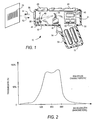
- reference numeral 10 in FIG. 1 generally identifies a portable reader for electro-optically reading indicia such as bar code symbols.
- the reader 10 is preferably implemented as a gun shaped device, having a pistol-grip handle 53.
- a lightweight plastic housing 55 contains a light source 46, a detector 58, optics 57, signal processing circuitry 63, a programmed microprocessor 40, and a power source or battery pack 62.
- An exit window 56 at a front end of the housing 55 allows an outgoing light beam 51 to exit and incoming reflected light 52 to enter.
- An operator aims the reader at a bar code symbol 70 from a position in which the reader 10 is spaced from the symbol, i.e., not touching the symbol or moving across the symbol.
- the optics 57 may include a suitable lens (or multiple lens system) to focus the light beam 51 into a scanning spot at an appropriate reference plane.
- the light source 46 such as a semiconductor laser diode, introduces a light beam into an optical axis of the lens 57, and other lenses or beam shaping structures as needed.
- the beam is reflected from an oscillating mirror 59 which is coupled to a scanning drive motor 60 energized when a trigger 54 is manually pulled.
- the oscillation of the mirror 59 causes the outgoing beam 51 to scan back and forth in a desired pattern, such as a scan line or a raster pattern of scan lines, across the symbol.
- the light 52 reflected or scattered back by the symbol 70 passes back through the window 56 for transmission to the detector 58.
- the reflected light reflects off the mirror 59, passes through an optical bandpass filter 47 and impinges on the light sensitive detector 58.
- the filter 47 is typically designed to have a bandpass characteristic in order to pass the reflected (return) laser light and block the light coming from other optical sources.
- the detector 58 produces an analog signal proportional to the intensity of the reflected light 52.
- the signal processing circuitry includes a digitizer 63 mounted on a printed circuit board 61.
- the digitizer processes the analog signal from detector 58 to produce a pulse signal where the widths and spacings between the pulses correspond to the widths of the bars and the spacings between the bars of the symbol.
- the digitizer serves as an edge detector or wave shaper circuit, and a threshold value set by the digitizer determines what points of the analog signal represent bar edges.
- the pulse signal from the digitizer 63 is applied to a decoder, typically incorporated in the programmed microprocessor 40 which will also have associated program memory and random access data memory.
- the microprocessor decoder 40 first determines the pulse widths and spacings of the signal from the digitizer.
- the decoder then analyzes the widths and spacings to find and decode a legitimate bar code message. This includes analysis to recognize legitimate characters and sequences, as defined by the appropriate code standard. This may also include an initial recognition of the particular standard to which the scanned symbol conforms. This recognition of the standard is typically referred to as autodiscrimination.
- the operator aims the bar code reader 10 and operates the movable trigger switch 54 to activate the light source 46, the scanning motor 60 and the signal processing circuitry. If the scanning light beam 51 is visible, the operator can see a scan pattern on the surface on which the symbol appears and adjust aiming of the reader 10 accordingly. If the light beam 51 produced by the source 46 is marginally visible, an aiming light may be included. The aiming light, if needed, produces a visible light spot which may be fixed, or scanned just like the laser beam 51. The operator employs this visible light to aim the reader at the symbol before pulling the trigger.
- the reader 10 may also function as a portable data collection terminal. If so, the reader would include a keyboard 48 and a display 49.
- the optical bandpass filter 47 is operative for filtering the light 52 traveling along a path to the photodetector 58.
- the light 52 passes through the window 56 to the mirror 59 for reflection therefrom through the filter 47 to the photodetector.
- An optional collection lens 45 may be used to focus the light 52 onto the photodetector. If the laser 46 emits a red beam having a wavelength on the order of 650 nm, then it is desired that the filter 47 only allows light in the vicinity of 650 nm to pass and reach the photodetector.
- FIG. 2 depicts a typical bandpass characteristic for the filter 47, in which a lower passband wavelength is set at about 625 nm at about 50% transmittance, and a higher passband wavelength is set at about 690 nm at about 50% transmittance.
- a lower passband wavelength is set at about 625 nm at about 50% transmittance
- a higher passband wavelength is set at about 690 nm at about 50% transmittance.
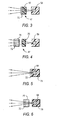
- the optical filter 47 comprises a plastic member 70 throughout which a dye, as represented by stippling, is distributed.
- the dye is devoid of cadmium and is operative for absorbing the light having wavelengths shorter than the lower passband wavelength.
- a dielectric coating 72 is likewise provided in the path and is operative for reflecting the light having wavelengths longer than the higher passband wavelength.
- the coating 72 is actually a plurality of reflective coatings applied one on top of another, each coating being a fraction of a micron in thickness and being reflective of light of a different wavelength so as to cause interference between light of different wavelengths.
- the coating 72 is applied directly on an outer surface of the red-colored plastic member 70.
- the dielectric coating 72 is applied on an outer surface of a glass plate 74.
- the application of the coating 72 is performed at elevated temperatures sufficient to melt or at least deform plastic, such as the plastic member 70.
- the coating 72 is performed on a glass plate.
- FIG. 4 depicts that the coated glass plate 74 and the red colored plastic member 70 are discrete elements spaced apart from one another. This was done for convenience of illustration because, in practice, the coated glass plate 74 is adhered directly to the red colored plastic member 70, typically with a light-transmissive glue.
- the glass plate 74 also serves as an ultraviolet light filter.
- FIG.5 embodiment depicts that the plastic member 70 encapsulates the photodiode 58.
- the photodiode 58 is often encapsulated in a plastic housing 76, and the embodiment of FIG.5 proposes that the dye be distributed throughout this plastic housing.
- the dielectric coating 72 can then be applied directly to the colored housing 76 as shown in FIG. 5 , or can be applied to the glass plate 74 either remote from the plastic housing 76 as shown in the illustrative example of FIG. 6 or adhered thereto.
- the lens 45 can be integrated into the filter.
- the lens 45 is constituted of glass, then the lens can serve as the glass plate 74 in the illustrative examples of FIGS. 4 and 6 .
- the lens 45 is constituted of plastic, then the lens can serve as the plastic member 70 in the embodiment of FIG. 3 and the illustrative example of FIG. 4 .
- FIG. 7 is analogous to FIG. 4 , except that the positions of the plastic member 70 and the glass plate have been reversed.
- the only difference between the illustrative examples of FIGS. 7-8 is that one of the surfaces of the plastic member is planar in FIG. 7 , whereas one of the surfaces of the plastic member is concave in FIG. 8 .
- the bandpass characteristic of the optical filter of FIG.7 is shown by a solid line in FIG. 9
- the bandpass characteristic of the optical filter of FIG.8 is shown by a broken line in FIG. 9 .
- the incident angle of the light impinging on the glass plate 74 in FIG. 7 is larger as compared to that of FIG.8 .
- the effective bandwidth of the filter characteristic is likewise reduced.
- the bandpass characteristic can be tuned.
- the electro-optical reader is compliant with governmental restrictions on the use of hazardous materials.
Landscapes
- Physics & Mathematics (AREA)
- General Physics & Mathematics (AREA)
- Optics & Photonics (AREA)
- Image Input (AREA)
- Facsimile Scanning Arrangements (AREA)
- Polarising Elements (AREA)
- Glass Compositions (AREA)
- Optical Filters (AREA)
Claims (7)
- Filtre passe-bande optique (47) pour filtrer la lumière se propageant le long d'un trajet vers un photodétecteur (58) dans un lecteur électro-optique (10) pour lire des marques, le filtre passe-bande optique (47) comprenant :a) un élément en matière plastique (70) dans le trajet ;b) un colorant dépourvu de métaux lourds, le colorant étant réparti dans l'élément en matière plastique (70) entier, le colorant pouvant être utilisé pour absorber la lumière ayant des longueurs d'onde plus courtes qu'une valeur inférieure de bande passante de 625 nm à une transmission de 50 % ; etc) un revêtement diélectrique (72) sur l'élément en matière plastique (70) et opérationnel pour réfléchir la lumière ayant des longueurs d'onde plus longues qu'une valeur supérieure de bande passante de 690 nm à une transmission de 50 o, °de sorte que le filtre permette sensiblement à la majeure partie de la lumière ayant des longueurs d'onde entre 625 nm et 690 nm d'atteindre le photodétecteur (58) tout en bloquant sensiblement la majeure partie de la lumière ayant des longueurs d'onde à l'extérieur de ces longueurs d'onde.
- Filtre passe-bande optique (47) selon la revendication 1, dans lequel le colorant a une couleur rouge.
- Filtre passe-bande optique (47) selon la revendication 1 ou la revendication 2, dans lequel le revêtement diélectrique (72) est sur une surface extérieure de l'élément en matière plastique (70) et comprend une pluralité de revêtements réfléchissants appliqués les uns au-dessus des autres, chaque revêtement ayant une épaisseur d'une fraction d'un micron et réfléchissant la lumière à une longueur d'onde différente, de manière à provoquer une interférence entre les lumières de différentes longueurs d'onde.
- Filtre passe-bande optique (47) selon l'une quelconque des revendications 1 à 3, dans lequel l'élément en matière plastique est une lentille de collecte.
- Combinaison d'un photodétecteur (58) et du filtre passe-bande optique (47) selon l'une quelconque des revendications précédentes, dans laquelle l'élément en matière plastique (70) entoure le photodétecteur (58).
- Combinaison du photodétecteur (58) et du filtre passe-bande optique (47) selon la revendication 5, dans laquelle l'élément en matière plastique (70) réalise un logement, encapsulant le photodétecteur (58).
- Lecteur électro-optique (10) pour lire des marques, le lecteur électro-optique comprenant un filtre passe-bande optique (47) selon l'une quelconque des revendications 1 à 4, ou la combinaison du photodétecteur et du filtre passe-bande optique (47) selon la revendication 5 ou la revendication 6.
Applications Claiming Priority (2)
| Application Number | Priority Date | Filing Date | Title |
|---|---|---|---|
| US11/225,321 US7180052B1 (en) | 2005-09-13 | 2005-09-13 | Non-heavy metal optical bandpass filter in electro-optical readers |
| PCT/US2006/034016 WO2007032920A2 (fr) | 2005-09-13 | 2006-08-31 | Filtre passe-bande optique fait d'un metal non lourd utilise dans les dispositifs de lecture electro-optiques |
Publications (3)
| Publication Number | Publication Date |
|---|---|
| EP1925014A2 EP1925014A2 (fr) | 2008-05-28 |
| EP1925014A4 EP1925014A4 (fr) | 2012-03-21 |
| EP1925014B1 true EP1925014B1 (fr) | 2015-06-10 |
Family
ID=37744957
Family Applications (1)
| Application Number | Title | Priority Date | Filing Date |
|---|---|---|---|
| EP06790116.5A Active EP1925014B1 (fr) | 2005-09-13 | 2006-08-31 | Filtre passe-bande optique fait d'un metal non lourd utilise dans les dispositifs de lecture electro-optiques |
Country Status (5)
| Country | Link |
|---|---|
| US (1) | US7180052B1 (fr) |
| EP (1) | EP1925014B1 (fr) |
| JP (1) | JP2009508163A (fr) |
| CN (1) | CN101263574B (fr) |
| WO (1) | WO2007032920A2 (fr) |
Families Citing this family (9)
| Publication number | Priority date | Publication date | Assignee | Title |
|---|---|---|---|---|
| US7874487B2 (en) | 2005-10-24 | 2011-01-25 | Cognex Technology And Investment Corporation | Integrated illumination assembly for symbology reader |
| US9070031B2 (en) | 2003-10-24 | 2015-06-30 | Cognex Technology And Investment Llc | Integrated illumination assembly for symbology reader |
| US7823783B2 (en) | 2003-10-24 | 2010-11-02 | Cognex Technology And Investment Corporation | Light pipe illumination system and method |
| US7823789B2 (en) | 2004-12-21 | 2010-11-02 | Cognex Technology And Investment Corporation | Low profile illumination for direct part mark readers |
| US9536124B1 (en) | 2003-10-24 | 2017-01-03 | Cognex Corporation | Integrated illumination assembly for symbology reader |
| US7604174B2 (en) | 2003-10-24 | 2009-10-20 | Cognex Technology And Investment Corporation | Method and apparatus for providing omnidirectional lighting in a scanning device |
| US7617984B2 (en) | 2004-12-16 | 2009-11-17 | Cognex Technology And Investment Corporation | Hand held symbology reader illumination diffuser |
| US9292724B1 (en) | 2004-12-16 | 2016-03-22 | Cognex Corporation | Hand held symbology reader illumination diffuser with aimer optics |
| WO2019163368A1 (fr) * | 2018-02-21 | 2019-08-29 | ソニーセミコンダクタソリューションズ株式会社 | Système de mesure de distance et module de réception de lumière |
Citations (1)
| Publication number | Priority date | Publication date | Assignee | Title |
|---|---|---|---|---|
| US4659178A (en) * | 1984-05-02 | 1987-04-21 | Minolta Camera Kabushiki Kaisha | Optical filter |
Family Cites Families (6)
| Publication number | Priority date | Publication date | Assignee | Title |
|---|---|---|---|---|
| US4969716A (en) * | 1989-04-03 | 1990-11-13 | Optical Coating Laboratory, Inc. | Solder sealed bandpass filter and method of making |
| JP3506618B2 (ja) * | 1998-11-18 | 2004-03-15 | ウシオ電機株式会社 | 黄色光放射用白熱電球 |
| US20020005509A1 (en) * | 1999-01-21 | 2002-01-17 | Chia-Chi Teng | Dye combinations for image enhancement filters for color video displays |
| CN2480915Y (zh) * | 2001-04-23 | 2002-03-06 | 张玉君 | 条码扫描机的滤光构造 |
| DE10141102A1 (de) * | 2001-08-22 | 2003-04-03 | Schott Glas | Cadmiumfreie optische Steilkantenfilter |
| US20030209669A1 (en) * | 2002-05-09 | 2003-11-13 | Chou Bruce C. S. | Miniaturized infrared gas analyzing apparatus |
-
2005
- 2005-09-13 US US11/225,321 patent/US7180052B1/en not_active Expired - Lifetime
-
2006
- 2006-08-31 CN CN2006800335969A patent/CN101263574B/zh active Active
- 2006-08-31 EP EP06790116.5A patent/EP1925014B1/fr active Active
- 2006-08-31 JP JP2008530104A patent/JP2009508163A/ja not_active Withdrawn
- 2006-08-31 WO PCT/US2006/034016 patent/WO2007032920A2/fr not_active Ceased
Patent Citations (1)
| Publication number | Priority date | Publication date | Assignee | Title |
|---|---|---|---|---|
| US4659178A (en) * | 1984-05-02 | 1987-04-21 | Minolta Camera Kabushiki Kaisha | Optical filter |
Also Published As
| Publication number | Publication date |
|---|---|
| CN101263574B (zh) | 2012-05-02 |
| CN101263574A (zh) | 2008-09-10 |
| WO2007032920A3 (fr) | 2007-07-05 |
| US20070057162A1 (en) | 2007-03-15 |
| WO2007032920A2 (fr) | 2007-03-22 |
| US7180052B1 (en) | 2007-02-20 |
| EP1925014A4 (fr) | 2012-03-21 |
| EP1925014A2 (fr) | 2008-05-28 |
| JP2009508163A (ja) | 2009-02-26 |
Similar Documents
| Publication | Publication Date | Title |
|---|---|---|
| US7963447B2 (en) | Enhanced monitoring of laser output power in electro-optical readers | |
| US6330974B1 (en) | High resolution laser imager for low contrast symbology | |
| US5923021A (en) | Light collection systems in electro-optical readers | |
| EP2593901B1 (fr) | Moteur de balayage muni d'un capteur d'objet intégré installé dans les lecteurs électro-optiques | |
| EP1925014B1 (fr) | Filtre passe-bande optique fait d'un metal non lourd utilise dans les dispositifs de lecture electro-optiques | |
| US8840027B2 (en) | Electro-optical reader with enhanced laser light pattern visibility | |
| US6992846B2 (en) | Micro reader scan engine with prism | |
| EP1924951A2 (fr) | Ensembles de commande de puissance laser dans des lecteurs optoélectroniques | |
| EP2294461B1 (fr) | Système d'imagerie ayant un agrandissement anamorphosé | |
| US6705525B2 (en) | Scanning system with adjustable optical characteristics | |
| US5272353A (en) | Retro-reflective scanner with return path free of collection optics | |
| US7007848B2 (en) | Arrangement for generating asymmetrical green laser beam | |
| WO2006071467A2 (fr) | Procedes et dispositifs pour ameliorer les performances d'un lecteur optique de marques de pieces directes | |
| US8028918B2 (en) | Enhanced monitoring of laser output power in electro-optical readers | |
| US7428999B2 (en) | MEMS-based electro-optical reader and method with extended working range | |
| US5949068A (en) | Optical reader for scanning optical indicia by way of varying object distance | |
| US7178734B1 (en) | Barcode scanner including a multitasking pattern mirror | |
| US20070047605A1 (en) | Laser power control arrangements in electro-optical readers | |
| KR930002268Y1 (ko) | 바코드 스캐너 장치 | |
| JPH01214990A (ja) | バーコード | |
| JPH02275597A (ja) | バーコードリーダ | |
| US20090108075A1 (en) | Sealed housing with integral window and integral pressure indicator in electro-optical reader |
Legal Events
| Date | Code | Title | Description |
|---|---|---|---|
| PUAI | Public reference made under article 153(3) epc to a published international application that has entered the european phase |
Free format text: ORIGINAL CODE: 0009012 |
|
| 17P | Request for examination filed |
Effective date: 20080226 |
|
| AK | Designated contracting states |
Kind code of ref document: A2 Designated state(s): DE FR GB |
|
| RBV | Designated contracting states (corrected) |
Designated state(s): DE FR GB |
|
| A4 | Supplementary search report drawn up and despatched |
Effective date: 20120222 |
|
| RIC1 | Information provided on ipc code assigned before grant |
Ipc: G02B 5/28 20060101ALI20120216BHEP Ipc: H01J 3/14 20060101AFI20120216BHEP |
|
| DAX | Request for extension of the european patent (deleted) | ||
| 17Q | First examination report despatched |
Effective date: 20130726 |
|
| GRAP | Despatch of communication of intention to grant a patent |
Free format text: ORIGINAL CODE: EPIDOSNIGR1 |
|
| INTG | Intention to grant announced |
Effective date: 20150202 |
|
| GRAS | Grant fee paid |
Free format text: ORIGINAL CODE: EPIDOSNIGR3 |
|
| GRAA | (expected) grant |
Free format text: ORIGINAL CODE: 0009210 |
|
| AK | Designated contracting states |
Kind code of ref document: B1 Designated state(s): DE FR GB |
|
| REG | Reference to a national code |
Ref country code: GB Ref legal event code: FG4D |
|
| REG | Reference to a national code |
Ref country code: DE Ref legal event code: R096 Ref document number: 602006045666 Country of ref document: DE |
|
| REG | Reference to a national code |
Ref country code: DE Ref legal event code: R097 Ref document number: 602006045666 Country of ref document: DE |
|
| PLBE | No opposition filed within time limit |
Free format text: ORIGINAL CODE: 0009261 |
|
| STAA | Information on the status of an ep patent application or granted ep patent |
Free format text: STATUS: NO OPPOSITION FILED WITHIN TIME LIMIT |
|
| 26N | No opposition filed |
Effective date: 20160311 |
|
| REG | Reference to a national code |
Ref country code: FR Ref legal event code: PLFP Year of fee payment: 11 |
|
| REG | Reference to a national code |
Ref country code: DE Ref legal event code: R082 Ref document number: 602006045666 Country of ref document: DE Representative=s name: LKGLOBAL | LORENZ & KOPF PARTG MBB PATENTANWAE, DE Ref country code: DE Ref legal event code: R082 Ref document number: 602006045666 Country of ref document: DE Representative=s name: KOPF, KORBINIAN, DIPL.-ING.UNIV., MA, DE |
|
| REG | Reference to a national code |
Ref country code: FR Ref legal event code: PLFP Year of fee payment: 12 |
|
| REG | Reference to a national code |
Ref country code: DE Ref legal event code: R082 Ref document number: 602006045666 Country of ref document: DE Representative=s name: LKGLOBAL | LORENZ & KOPF PARTG MBB PATENTANWAE, DE |
|
| REG | Reference to a national code |
Ref country code: FR Ref legal event code: CA Effective date: 20171120 Ref country code: FR Ref legal event code: CD Owner name: SYMBOL TECHNOLOGIES, INC., US Effective date: 20171120 Ref country code: FR Ref legal event code: CJ Effective date: 20171120 |
|
| REG | Reference to a national code |
Ref country code: FR Ref legal event code: PLFP Year of fee payment: 13 |
|
| P01 | Opt-out of the competence of the unified patent court (upc) registered |
Effective date: 20230416 |
|
| PGFP | Annual fee paid to national office [announced via postgrant information from national office to epo] |
Ref country code: DE Payment date: 20250724 Year of fee payment: 20 |
|
| PGFP | Annual fee paid to national office [announced via postgrant information from national office to epo] |
Ref country code: GB Payment date: 20250725 Year of fee payment: 20 |
|
| PGFP | Annual fee paid to national office [announced via postgrant information from national office to epo] |
Ref country code: FR Payment date: 20250723 Year of fee payment: 20 |