EP1923705A1 - Seal member, cap of reagent container, and reagent container - Google Patents
Seal member, cap of reagent container, and reagent container Download PDFInfo
- Publication number
- EP1923705A1 EP1923705A1 EP06782194A EP06782194A EP1923705A1 EP 1923705 A1 EP1923705 A1 EP 1923705A1 EP 06782194 A EP06782194 A EP 06782194A EP 06782194 A EP06782194 A EP 06782194A EP 1923705 A1 EP1923705 A1 EP 1923705A1
- Authority
- EP
- European Patent Office
- Prior art keywords
- retainer
- reagent container
- opening
- sealing
- cap
- Prior art date
- Legal status (The legal status is an assumption and is not a legal conclusion. Google has not performed a legal analysis and makes no representation as to the accuracy of the status listed.)
- Withdrawn
Links
Images


Classifications
-
- G—PHYSICS
- G01—MEASURING; TESTING
- G01N—INVESTIGATING OR ANALYSING MATERIALS BY DETERMINING THEIR CHEMICAL OR PHYSICAL PROPERTIES
- G01N35/00—Automatic analysis not limited to methods or materials provided for in any single one of groups G01N1/00 - G01N33/00; Handling materials therefor
- G01N35/10—Devices for transferring samples or any liquids to, in, or from, the analysis apparatus, e.g. suction devices, injection devices
- G01N35/1079—Devices for transferring samples or any liquids to, in, or from, the analysis apparatus, e.g. suction devices, injection devices with means for piercing stoppers or septums
-
- G—PHYSICS
- G01—MEASURING; TESTING
- G01N—INVESTIGATING OR ANALYSING MATERIALS BY DETERMINING THEIR CHEMICAL OR PHYSICAL PROPERTIES
- G01N35/00—Automatic analysis not limited to methods or materials provided for in any single one of groups G01N1/00 - G01N33/00; Handling materials therefor
- G01N35/10—Devices for transferring samples or any liquids to, in, or from, the analysis apparatus, e.g. suction devices, injection devices
- G01N35/1002—Reagent dispensers
Definitions
- the present invention relates to a sealing member, a cap for a reagent container, and a reagent container.
- a number of open reagent containers are arranged along circumferential direction of a rotatable table provided in a reagent storage, and reagent is dispensed in a reactor vessel by rotating the table to a dispensing position.
- the automatic analyzer is placed in a condition, typically, such that the inside of the reagent storage is cooled to temperatures of 5 to 10°C with a low humidity, to prevent degradation of reagent.
- specially-structured caps are attached to the containers to prevent contained reagents from evaporation.
- Patent Document 1 Japanese patent application laid-open No. 2004-177255
- Patent Document 2 Japanese patent application laid-open No. H11-194132
- Patent Document 3 Japanese patent application laid-open No. 2004-177254
- the cap for the reagent container disclosed in Patent Document 1 is provided with a connecting portion linked to a holding member that holds a sealing body to seal an opening of the reagent container.
- the cap for the reagent container is opened or closed by connecting the connection portion to an end of an arm-shaped opening and closing device that is rotatably supported and has a resilient part, and by raising or dropping the holding member with the connecting portion, acting or releasing a pressure onto the opening and closing device.
- the cap of Patent Document 1 transmits a rotation of the arm-shaped opening and closing device to the holding member via the connecting portion.
- the sealing body of Patent Document 1 tends to be misaligned by moving toward the direction of the connection of the opening and closing device, the connecting portion, and the holding member to which stress is transmitted, when the opening of the reagent container is opened and closed.
- a problem is that opening and closing movement of the sealing body is disturbed because the opening and closing device side of the sealing body falls into the opening, when the holding member is raised or is dropped.
- the cap of Patent Document 1 is composed of many components and has a complex structure.
- the cap of Patent Document 2 requires a space to move in the lateral direction, since the cap is adapted to rotate upward from the position of seal in the lateral direction of the reagent container.
- the reagent container using the cap of Patent Document 1 needs a large space if it is mounted on an automatic analyzer, resulting in an increase in size of the automatic analyzer.
- the cap disclosed in Patent Document 3 does not have such a problem that the cap of Patent Document 2 has.
- the cap of Patent Document 3 presses a sealing body that seals an opening of a container from above by an opening and closing device, and opens up an aperture by pushing the sealing body toward along a slit extending radially from its center.
- the sealing body returns an original condition by releasing the pressing force.
- the cap of Patent Document 3 opens its center and forms an aperture-shaped through-hole to insert an extracting probe for extracting the reagent to a center of the opening and closing device.
- the sealing body with the slit is located in the bottom of through-hole.
- a sealing member which seals an opening of a reagent container, prevented from falling into the opening when opening and closing and allowing smooth opening and closing action, and a cap of a reagent container which is composed of a small number of components and has a simple structure.
- a second object of the present invention is to provide a cap for a reagent container, when used in an automatic analyzer, which prevents liquid from break-in although dew condensation water in a reagent storage or reagent in other reagent containers spatters, and which reduces an opportunity of a contamination.
- a sealing member of an aspect of the present invention includes a sealing portion that is used for a cap attached to a reagent container and covers an opening of the cap with an open-close movement by flapping around a predetermined point.
- the sealing portion has, on an outer circumference in the predetermined point side, an extending portion that extends outward of the opening, and the extending portion contacts with an upper edge of the opening when the sealing portion covers the opening.
- a positioning portion that positions the extending portion in the predetermined point side.
- a cap for a reagent container of an aspect of the present invention is attached to a cylindrical opening of a main body containing a reagent, and includes a retainer that has an insertion cylinder connected to the cylindrical opening and that is attached to the cylindrical opening, a slide member that slidably fits in the retainer to cover the retainer and that has a flap member being raised and laid by the insertion cylinder according to a sliding motion against the retainer, a sealing member that is supported by the flap member and that seals an opening of the insertion cylinder with an open-close movement, and a biasing member that is placed between the retainer and the slide member to press the slide member toward the opposite direction from the retainer and that gives a pressing force to make the sealing member seal the opening of the insertion cylinder via the slide member.
- a reagent container of an aspect of the present invention includes a cap attached to a cylindrical opening of a main body containing a reagent.
- the cap includes a retainer that has an insertion cylinder connected to the cylindrical aperture and that is attached to the cylindrical aperture, a slide member that slidably fits in the retainer to cover the retainer and that has a flap member being raised and laid by the insertion cylinder according to a sliding motion against the retainer, a sealing member that is supported by the flap member and that seals an opening of the insertion cylinder, and a biasing member that is placed between the retainer and the slide member to press the slide member toward the opposite direction from the retainer and that gives a pressing force to make the sealing member seal the opening of the insertion cylinder via the slide member.
- the sealing member is raised up along with the flap member by the insertion cylinder by sliding the slide member toward the retainer to open the opening.
- the insertion cylinder includes engaging protrusions at facing positions on an outer circumference of an upper part across a center of the cylinder, and the flap member includes a guiding portion that guides the raising and laying motion of the flap member by engaging each engaging protrusion to a corresponding facing position.
- the slide member in addition to the reagent container of the invention described above, includes, on an upper side, an adjusting portion adjusting the position of an operating means that slides the slide member toward the retainer.
- the flap member in addition to the reagent container of the invention described above, includes a positioning portion that determines a position at which the sealing member is supported.
- the flap member is formed in thin-walled, and has a hinge as a pivotal point of the raising and laying motion.
- the insertion cylinder in addition to the reagent container of the invention described above, includes a plurality of contact portions that contacts with a circumference of a bottom part of the hinge side of the sealing member, and that are formed on an outer circumference of an upper part.
- the sealing member of the present invention has, on the outer circumference in the predetermined side of the sealing portion, an extending portion that extends outward of the opening of the cap. Since the extending portion contacts with the upper edge of the opening when the sealing portion covers the opening, the extending portion restricts the sealing member not to fall into the opening. Thus, the sealing member of the present invention smoothly opens and closes, and the cap for the reagent container with the sealing member according to the present invention has a simple structure with a fewer parts.
- the reagent container of the present invention has the sealing member that is supported by the flap member of the slide member to close the opening of the insertion cylinder possessed by the retainer, and that slides the slide member toward the retainer side to open the opening of the insertion cylinder by raising along with the flap member.
- the reagent container of the present invention is effective to reduce occurrence of a contamination even if liquid such as condensed water in the reagent storage of the automatic analyzer and reagent from another reagent container spatters, because such liquid is difficult to enter the container.
- FIG. 1 is a front view showing the top of the reagent container and the cross-section of the cap.
- FIG. 2 is a front view showing right-side half sectional view of a retainer constituting the present invention.
- FIG. 3 is a plane view of the retainer.
- FIG. 4 is a cross-sectional view taken along the line C1-C1 of the retainer in FIG. 3 .
- a reagent container 1 is formed from a synthetic resin such as a high-density polyethylene (HDPE), and a cap 2 is attached to a cylindrical aperture 1b formed in an upper part of a main body 1a as shown in FIG. 1 .
- the main body 1a is shaped like a cylinder, is provided with a flat portion 1c on a part of a side surface to attach an information label hereon, and is formed a male screw on an outer surface of the cylindrical aperture 1b.
- a type of reagent contained in the reagent container 1 or an expiration date is stored on the information label.
- the cap 2 includes a retainer 3, a slide member 4, a sealing member 5, and a biasing member 6, and seals the cylindrical aperture 1b of the reagent container 1 in such a manner that the cap 2 is openable and closable.
- the retainer 3 is formed from a synthetic resin such as a polyethylene, and includes an attachment portion 3a that is attached to the cylindrical aperture 1b of the reagent container 1 by screwing, a guiding cylinder 3b that is linked to the attachment portion 3a, and an insertion cylinder 3c that is arranged in a center of the guiding cylinder 3b, as shown in FIGS. 1 to 8 .
- the attachment portion 3a is provided with a knurling 3d that is adapted to be rotated by a fingertip (see FIGS. 2 and 5 ) on its outer surface, and a female screw on an inner surface.
- the guiding cylinder 3b is provided with an engaging portion 3e on an outer circumference of its upper side.
- the insertion cylinder 3c is communicated with the cylindrical aperture 1b at the bottom part, and is a cylinder in which a dispensing probe of the automatic analyzer is inserted from above.
- the insertion cylinder 3c is adapted to prevent evaporation and quality change of the reagent inside the regent container 1 and entry of a liquid from outside, by sealing an upper opening 3f with the sealing member 5 with a close-open motion.
- the insertion cylinder 3c is provided, on its upper part, with flat portions 3g in which portions to face each other are arranged to be parallel to one another, as shown in FIGS. 3 and 4 .
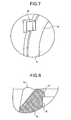
- the flat portions 3g is provided, on the outer circumference of the upper part, with engaging protrusions 3h that are arranged at opposed positions across the center axis of the insertion cylinder 3c (see FIGS. 2 to 5 ). Also, the insertion cylinder 3c is provided, around the bottom, with a contact cylinder 3j that extends toward the attachment portion 3a and contacts with the inside of the cylindrical aperture 1b, as shown in FIGS. 2 and 4 . The insertion cylinder 3c is provided with two ribs 3k as contact portions on the outer circumference of the upper part adjacent to the engaging protrusions 3h, as shown in FIGS. 3 and 7 . The insertion cylinder 3c, as shown in FIG.
- the protrusion 3m and the sealing portion 3n are formed to have smooth surfaces without bumps since they contact with a bottom surface of a sealing portion 5g of the sealing member 5 to seal the upper opening 3f.
- a slide member 4 is formed from a synthetic resin such as a polyethylene, is attached to the retainer 3 to freely slide in the vertical direction by fitting it into the retainer 3 from above, and covers the top of the retainer 3.
- a slide cylinder 4b is vertically and integrally fixed to an outer circumference of a top panel 4a.
- the sealing member 5 is held by a flap member 4h.
- the top panel 4a is provided with convex portions 4c, 4d along a circumference near the outer circumference of the upper part.
- the convex portion 4c is configured to be longer than the convex portion 4d.
- Each convex portion 4c, 4d is provided, on the outer circumferences, with a plurality of position control ribs 4e that is arranged in a radial pattern and becomes gradually lower outward.
- the plurality of position control ribs 4e as shown in FIG. 10 , are arranged on the circumference of the same radius center which is an insertion hole 4i.
- the top panel 4a is provided, at its center, with the flap member 4h formed by an opening 4g and a hinge 4f of which a portion adjacent to the convex portion 4d is thin-walled.
- the flap member 4h has at its center the insertion hole 4i in which the sealing member 5 is inserted.
- the insertion hole 4i is provided with a concave 4j that positions the sealing member 5 on the opposite side facing the hinge 4f (see FIGS. 10 and 14 ).
- the flap member 4h is provided with guiding piece 4k that is vertically attached to the flap member 4h and guides the raising and laying of the flap member 4h to the position facing each other adjacent to the hinge 4f.
- the flap member 4h is provided with a protrusion P disposed on the both side of bottom surface between the hinge 4f and the insertion hole 4i in the radial direction centering the insertion hole 4i (see FIGS. 10 and 14 ).
- the guiding piece 4k is provided with a guiding hole 4m that engages with an engaging protrusion 3h of the retainer 3 (see FIGS. 13 and 15 ).
- the guiding hole 4m as shown in FIG. 15 , is composed of a long hole Hh that extends in the horizontal direction to the top panel 4a and a long hole Hs that is inclined to the plane of the top panel 4a.
- two guiding pieces 4k as shown in FIG. 15 , is provided with a slanted ditch 4n disposed in a facing position that is deep in the hemline side and becomes shallower toward the guiding hole 4m.
- the slanted ditch 4n leads the engaging protrusion 3h provided in the retainer 3 to the guiding hole 4m.
- the flap member 4h is provided with a concave 4p that is slightly concaved between the hinge 4f and the insertion hole 4i on the under surface.
- the concave 4p regulates the movement, when the sealing member 5 is raised or laid together with the flap member 4h to open or close the upper opening 3f, such that the slanted portion 5k of the sealing member 5 does not contact with the under surface of the flap member 4h.
- a ditch instead of a long hole could be used for the guiding piece 4k as long as engaging with the engaging protrusion 3h.
- the slide cylinder 4b is arranged on the outer circumference of the guiding cylinder 3b, and is provided with the bottom engaging pieces 4t via slits 4s at three places along the circumferential direction as shown in FIGS. 9 and 11 to 14 .
- Each engaging piece 4t by putting a protrusion 4u inside the bottom part and the engaging portion 3e formed on the outer circumference of the upper part of the guiding cylinder 3b in engagement, regulates the raising position of the slide member 4 and regulates so that the slide member 4 does not uncouple from the retainer 3.
- the sealing member 5, for example, is formed from a synthetic resin having elasticity such as an ethylene-polyethylene terpolymer (EPDM), seals the upper opening 3f of the retainer 3 by being held by the flap member 4h, and opens and closes the upper opening 3f by raising and laying the flap member 4h.
- the holding portion 5a is provided with a small diameter portion 5d between an upper locking part 5b and a lower locking part 5c, and is provided with a disk-shaped sealing portion 5g under the lower locking part 5c.
- the holding portion 5a is provided with a bore 5e that is bored from the level of the upper locking part 5b to the level of midway between the upper locking part 5b and the small diameter portion 5d, at the radial center the upper locking part 5b.
- the holding portion 5a can be easily deformed in the upper locking part 5b to the small diameter portion 5d because of the bore 5e, and thus can be easily attached to the insertion hole 4i formed in the flap member 4h.
- the holding portion 5a is provided with a positioning rib 5f that guides a concave 4j of the flap member 4h to fit in the small diameter portion 5d in order to position a flange 5j in the hinge 4f side.
- the sealing portion 5g has a diameter between the inner diameter of the upper opening 3f and the outer diameter of the upper part of the insertion cylinder 3c, and a slanted portion 5k that becomes lower toward the outward of the outer circumference of the upper part.
- the slanted portion 5k is formed on the outer circumference of the upper surface of the sealing portion 5g to put in the position of the concave 4p when the sealing member 5 is attached to the flap member 4h (see FIGS. 14 , 15 ).
- the sealing portion 5g is provided with a seal convex 5i that bulges downward on the outer circumference of the bottom part, which is formed by the concave 5h arranged along the circumferential direction toward the radial center of the bottom surface.
- the sealing portion 5g is also provided, on the opposed side that faces with the positioning rib 5f across the bore 5e, with the quadrangular flange 5j that extends outward in the radial direction.
- the flange 5j is placed on the side of the hinge 4f by engaging the positioning rib 5f with the concave 4j, and the flange 5j contacts with the upper edge of the upper opening 3f and the upper surface of two ribs 3k arranged on the outer circumference of the upper part of the insertion cylinder 3c when the flap member 4h is raised or laid. Therefore, flange 5j regulates the movement such that the side of the hinge 4f of the sealing portion 5g does not fall into the upper opening 3f when the flap member 4h is raised or laid.
- the length of extension toward the hinge 4f is determined by considering the distance by which the upper opening 3f of the sealing member 5 shifts outward in the radial direction along with the raising and laying motion of the flap member 4h.
- the sealing portion 5g is given elasticity by forming the concaves 5h, the seal convex 5i adheres tightly to the sealing portion 3n (see FIG. 8 ).
- the biasing member 6 is arranged between the retainer 3 and the slide member 4, and biases the slide member 4 upward to separate the slide member 4 from the retainer 5.
- the biasing member 6 is a coil spring that applies a pressing force to the sealing member 5 to seal the upper opening 3f.
- the biasing member 6 is formed from a synthetic resin such as a polyacetal resin (POM), and formed by stacking two spring units 61 and a spring unit 62, as shown in FIGS. 19 to 22 .
- the spring units 61 includes ring-shaped supporting members 61b disposed in the both side of a coil portion 61a and the coil portion 61a.
- the coil portion 61a has a turning number of a 1/2.
- Two coil member 61c which turns in a right-handed direction, is connected to the supporting members 61 disposed on their both sides in such a manner that their joining are arranged in symmetrical positions (an angle of 180°) on their circumferences.
- Each supporting member 61b is provided with protrusions 61d (see FIG. 22 ) at a plurality of positions of the bottom surface.
- the spring unit 62 includes a coil portion 62a and a supporting portion 62b, and is configured almost the same as the spring unit 61.
- the spring unit 62 is provided with two coil members 62c that turns in the left-handed direction, and the supporting portion 62b disposed in the upper part includes concaves 62d (see FIGS. 21 and 22 ) at a plurality of positions on the upper surface.
- the concaves 62d position the spring unit 61 and the spring position 62 such that the spring unit 61 comes, along the circumference, ahead of the spring position 62 by 90° when the concaves 62d engage with the protrusions 61d.
- a force exerted by the spring units 61, 62 is increased by giving a greater pitch angle than 20° or a greater turning number than 1/2.
- the coil member 61c, 62c of the spring units 61, 62 tend to bulge outward from the central axis in the radial direction when compressed. If the bulging of the spring units 61, 62 occurs, the outer surface of the spring units 61, 62 that bulge outward contacts with the inner surface of the guiding cylinder 3b of the retainer 3 or the slide cylinder 4b of the slide member 4, so the function of the spring units 61, 62 is harmed, and the force exerted by the springs is weaken by these contact or friction caused by the contacts.
- the spring units 61, 62 cannot have an enough spring force if the tuning number or the pitch angle is too small.
- the biasing member 6, as shown in FIG. 22 is manufactured by stacking the spring unit 61 and the spring unit 62, and by engaging the concaves 62d with the corresponding protrusions 61d respectively.
- the biasing member 6 can be made by bonding, with bond, the supporting portion 61b and the supporting portion 62b of the spring unit 61 and the spring unit 62, respectively, that face each other. Also, if the spring unit 61 and the spring unit 62 are used by themselves, the coil member 61b and the coil member 62b may rotate according to the turning direction of the coil member 61c, 62c when expanded or contracted by applying force.
- the biasing member 6 which is made by stacking the spring unit 61 and the spring unit 62, each having a different turning direction, the rotational force is balanced out because the supporting portion 61b and the supporting portion 62b attempt to rotate in the different rotational directions although the supporting portion 61b and the supporting portion 62b rotate when expanded or contracted. Therefore, the biasing member 6 prevents the supporting portions 61b, 62b from rotational frictions to eliminate constraints for the expansion and contraction function of the coil members 61c, 62c, thus the biasing member 6 can effectively function as a spring.
- the biasing member 6 is made up by alternately stacking an odd number of the coil members 61c, 62c such that the turning direction of each coil member is different from that of the adjacent coil member, the aliquant coil member 61c, 62c is set to have a pitch angle of 20 degrees or below.
- the biasing member 6 can suppress the rotation of the supporting portion 61b and the supporting portion 62b caused by the aliquant coil member.
- the biasing member 6 is formed from a synthetic resin. As shown in FIG. 23 , two coil portions 6a are connected to three ring-shaped supporting portions 6b, and the turning direction of two coil members 6c can be the opposite directions, a right-handed direction and a left-handed direction, for each coil portion 6a.
- the reagent container 1 configured as described above is attached with the cap 2 by screwing the attachment portion 3a in the cylindrical aperture 1b after disposing the biasing member 6 on the inner circumference of the guiding cylinder 3b and assembling the cap 2 by attaching the slide member 4 to the retainer 3 from above.
- the cap 2 can be easily assembled.
- the sealing member 5 contacts with the upper edge of the upper opening 3f, and is provided, on the outer circumference of the sealing portion 5g, with the flange 5j as an extending part that extends outward of the upper opening 3f. Therefore, when raised and laid along with the flap member 4h, the sealing member 5 regulates the flange 5j to contact with the upper edge of the upper opening 3f and the sealing portion 5g not to fall into the upper opening 3f, so that the sealing member 5 causes a smooth opening and closing. Also, the cap 2 with the sealing member 5 has a simpler structure as compared with a conventional cap, and costs less to manufacture because of a fewer number of parts.
- the retainer 3 is provided with the knurling 3d on the outer surface of the attachment potion 3a, one can easily screw the attachment portion 3a into the cylindrical aperture 1b with his finger tips.
- the slide member 4 is provided with the engaging pieces 4t via the slits 4s at three sections of bottom part of the slide cylinder 4b, the protrusion 4u can easily engage with the engaging portion 3e formed on the upper part of the guiding cylinder 3b of the retainer 3.
- the slide member 4 can freely slide along the guiding cylinder 3b between the attachment portion 3a and the engaging portion 3e without running off the retainer 3 although the biasing member 6 pushed the slide member 4 upward to separate from the retainer 3.
- the slide member 4 is provided with the slanted ditches 4n inside the guiding piece 4k that faces to one another, when the slide member 4 is put on the retainer 3, the engaging protrusions 3h are guided by the corresponding slanted ditches 4n and smoothly engage with the guiding holes 4m.
- the reagent container 1 including the biasing member 6 is all formed from a synthetic resin, it has an advantage that scraping is easily done because there is no need to collect a coil spring made of metal, compared with a conventional reagent container with a metallic coil spring as a biasing member.
- the automatic analyzer 10 includes a mounting table 11 that holds a plurality of the reagent containers 1 in a circle thereon and rotates, storage case 12 that keeps the plurality of reagent containers 1 on the mounting table 11 at a certain temperature (for example, 5 to 10°C) by a cooling means (not shown in figures), a cap opening device 20 that selectively opens the cap 2 which seals the cylindrical aperture 1b of the reagent container 1, and a controller 19 that drives the cap opening device 20 to release the cylindrical aperture 1b from sealing by the cap 2 and that drops and inserts a probe 30 into the regent container 1.
- a certain temperature for example, 5 to 10°C
- the mounting table 11 is coupled to a shaft 16 that is rotatably supported by a bearing 15.
- the shaft 16 includes a gear 16a that engages with a gear 18a connected to a motor 18.
- the mounting table 11 is adapted to rotate for a predetermined amount by activating the motor 18 with a command from the controller 19 and by rotating the shaft 16 via the gears 18a and 16a.
- the storage case 12 includes the cap opening device 20, a reagent house 13, and a lid 14 with an opening 14a for insertion of the probe 30.
- the cap opening device 20 is disposed inside the storage case 12.
- the cap opening device 20 includes an arm 21 that opens the cap 2 of the reagent containers 1, a slide shaft 22 that moves the arm 21 up and down, a rotary solenoid 24 that moves the slide shaft 22 up and down via a joint 23, and a guide 25 that guides the slide shaft 22.
- the arm 21 is provided with an opening 21a that is located immediately above the cap 2, and the opening 21a adjusts the position of the reagent container 1 relative to the arm 21 by engaging to a plurality of position control ribs 4e.
- the automatic analyzer 10 configured in this way drives, under the control of the controller 19, the motor 18 to position a selected reagent container 1, which corresponds to a selected analysis, just below the probe 30, and drives the opening device 20 to make the arm 21 press the cap 2 of the reagent container 1 downward.
- the cap 2 has, on the upper side of the top panel 4a, the plurality of position control ribs 4e that continuously become lower toward the outer circumference, the position of the reagent container 1 is adjusted to be in the same position relative to the arm 21 all time by making the plurality of position control ribs 4e and the opening 21a in engagement.
- the slide member 4 of the cap 2 is pressed down, accordingly, the flap member 4h is raised along with the sealing member 5 which is sealing the upper opening 3f of the insertion cylinder 3c, and the upper opening 3f is opened.
- the probe 30 is descended and inserted into the reagent container 1 through the upper opening 3f of the insertion cylinder 3c by a driving device (not shown in Figures) to suck the reagent.
- the automatic analyzer 10 stops driving of the opening device 20 and releases the cap 2 from pressure of the arm 21 after sucking the reagent, then, the biasing member 6 pushes up the slide member 4 with its pressuring force by the reverse method.
- the slide member 4 returns to the initial position, the flap member 4h is laid down, and the upper opening 3f of the insertion cylinder 3c is closed by the sealing member 5.
- the motion of the cap 2 during opening and closing will be described below with reference to FIGS. 25 to 31 .
- the slide member 4 is normally pressed upward by the pressing force of biasing member 6, and the upper opening 3f is closed with the sealing member 5 that has almost the same diameter as the upper opening 3f.
- the protrusion 3h that is formed on the upper part of the insertion cylinder 3c as a fixed point engages with the long hole Hh that extends along the guiding hole 4m formed in the guiding piece 4k.
- the slide member 4 of the cap 2 is slightly pushed down by the arm 21 that is droved by the opening and closing device 20, and the guiding pieces 4k are slightly pushed up by the engaging protrusion 3h, so as shown FIG. 26 , the flap member 4h slightly rotates in counterclockwise direction around the hinge 4f to be almost horizontalized.
- the seal convex 5i (see FIG. 16 ) on the outer circumference in the lower part tightly fits to the sealing portion 3n (see FIG. 8 ) without clearance to cause the sealing member 5 to seal the upper opening 3f.
- the engaging protrusion 3h is located at the boundary of the long hole Hh that extends in horizontal direction of the guiding hole 4m and the long hole Hs that is slanted relative to the horizontal direction.
- the sealing member 5 starts to rise along with the flap member 4h.
- the sealing portion 5g has a diameter between an inner diameter of the upper opening 3f and an outer diameter of the upper part of the insertion cylinder 3c, and the flange 5, with its bottom side, contacts with the upper circumference of the upper opening 3f and the two ribs 3k provided on the outer circumference of the upper part of the insertion cylinder 3c.
- the sealing member 5 smoothly closes or opens without dropping the sealing portion 5g into the upper opening 3f. Also, as shown in FIG.
- the engaging protrusion 3h apparently moves to the end of the long hole Hh, and the flap member 4h rotates around the hinge 4f and rises at 90° relative to the horizontal plane.
- the reagent container 1 is fully opened in that the upper opening 3f of the insertion cylinder 3c is opened. Therefore, in this condition of the reagent container 1, the inside reagent is sucked by the probe 30 that is inserted from the upper opening 3f.
- the sealing member 5 smoothly closes and opens without dropping the sealing portion 5g into the upper opening 3f.
- the flap member 4h is linked with the top panel 4a by the thin-walled hinge 4f, the rising and laying action is smoothly carried out.
- the automatic analyzer 10 continuously carries out analysis for several kinds of item analysis by repeating these actions.
- the sealing member 5 contacts with the upper edge of the upper opening 3f, and the flange 5j is provided to the outer circumference of the sealing portion 5g on the hinge 4f side as an extending part that extends outward of the upper opening 3f. Therefore, when raised and laid down along with the flap member 4f, the sealing member 5 is regulated that the sealing portion 5g does not fall into the upper opening 3f by making the flange 5j contacts with the upper edge of the upper opening 3f.
- the sealing member 5 when the sealing member 5 is raised or laid down along with the flap member 4f to open or close the upper opening 3f, the flange 5j rises or lies, contacting with the upper edge of the upper opening 3f and the upper surface of two ribs 3k arranged on the outer circumference of the upper part of the insertion cylinder 3c, so the sealing member 5 is smoothly opens and closes without dropping the sealing portion 5g into the upper opening 3f.
- the sealing member 5 is provided with the positioning rib 5f, by fitting the positioning rib 5f into the concave 4j to attach the holding portion 5a in the insertion hole 4i, the sealing member 5 can position the flange 5j in the hinge 4f side without taking a wrong attaching direction.
- the cap 2 with the sealing member 5 has a simple structure as compared with a conventional cap disclosed in Patent Document 1, and costs less to manufacture because of a fewer number of parts.
- the slide member 4 is normally pressed upward by the pressing force of biasing member 6 to seal the upper opening 3f with the sealing member 5, and the upper opening 3f is opened only if the slide member 4 is pushed down when dispensing, etc.
- the sealing portion 5g is shaped in a discoid, is formed to become lower outward on the circumference of its upper part, and does not have a slit.
- the reagent container 1 prevents the reagent from vaporization, and if a liquid such as condensed water in the reagent storage 13 and a reagent in another reagent container 1 flies apart, the reagent container 1 prevents a liquid entering from a clearance between the opening 4g of the top panel 4a and the flap member 4h.
- the cap 2 has a simple structure and fewer parts as compared with a conventional cap, the cap 2 is supplied at a lower cost, thus the reagent container 1 is supplied at a lower cost.
- the attachment portion 3a is applied, on its outer surface, with the knurling 3d, so that the attachment portion 3a is easily screwed into the cylindrical aperture 1b by holding the knurling portion 3d with fingertips and rotating the retainer 3.
- the cap 2 is already assembled by attaching the slide member 4 to the retainer 3, the slide member 4 may come away from the retainer 3 because the slide member 4 may also rotate in circumferential direction when the retainer 3 is rotated.
- the cap 2 includes, at the bottom part of the engaging portion 3e on the outer surface of the guiding cylinder 3b of the retainer 3, two stoppers 3p that is place at a distance apart in the circumferential direction on above and below.
- the slide member 4 is provided, at a position adjacent to the two stoppers 3p, with three protrusions 4v that engage with the engaging portion 3e as shown in FIG. 32 .
- the three protrusions 4v are arranged in such a way that the middle protrusion 4v is placed between the two stoppers 3p, and the other two protrusions are arranged outside of the stoppers 3p.
- the slide member 4 is vertically turned over and attached to the retainer 3 as indicated by the arrow to make the protrusions 4v and the stopper 3p in engagement. Then, the protrusions 4u, 4v and the engaging portion 3e regulate the slide member 4 not to fall off from the retainer 3 even if the slide member 4 slides with respect to the retainer 3, and regulate the slide member 4 not to rotate in the circumferential direction with respect to the retainer 3 by placing the protrusions 4v and the stoppers 3p in engagement. These prevent the slide member 4 from falling off from the retainer 3.
- the sealing member of the present invention is effective to prevent itself, when the sealing member that seals the opening of the reagent container is raised or laid down, from falling into the opening, so the sealing member smoothly opens and closes.
- the cap with this sealing member is effective to reduce a number of parts and simplify its structure.
- the reagent container of the present invention is effective to reduce occurrence of a contamination if a liquid such as condensed water in the reagent storage of the automatic analyzer or a reagent from another reagent container flied apart, because it adapted for the liquid to be difficult to enter inside the container.
- the slide member can slide until it reaches the regulation portion without falling off even if pressed by the biasing member toward the opposite direction from the retainer.
- the slide member can make the engaging protrusions smoothly engage with the guiding portion.
Abstract
Description
- The present invention relates to a sealing member, a cap for a reagent container, and a reagent container.
- In a conventional automatic analyzer, a number of open reagent containers are arranged along circumferential direction of a rotatable table provided in a reagent storage, and reagent is dispensed in a reactor vessel by rotating the table to a dispensing position. At this time, the automatic analyzer is placed in a condition, typically, such that the inside of the reagent storage is cooled to temperatures of 5 to 10°C with a low humidity, to prevent degradation of reagent. Thus, in some conventional reagent containers, specially-structured caps are attached to the containers to prevent contained reagents from evaporation. (For example,
Patent Documents 1 to 3) - Patent Document 1: Japanese patent application laid-open No.
2004-177255
Patent Document 2: Japanese patent application laid-open No.H11-194132
Patent Document 3: Japanese patent application laid-open No.2004-177254 - In the meantime, the cap for the reagent container disclosed in
Patent Document 1 is provided with a connecting portion linked to a holding member that holds a sealing body to seal an opening of the reagent container. The cap for the reagent container is opened or closed by connecting the connection portion to an end of an arm-shaped opening and closing device that is rotatably supported and has a resilient part, and by raising or dropping the holding member with the connecting portion, acting or releasing a pressure onto the opening and closing device. In other words, the cap ofPatent Document 1 transmits a rotation of the arm-shaped opening and closing device to the holding member via the connecting portion. Therefore, the sealing body ofPatent Document 1 tends to be misaligned by moving toward the direction of the connection of the opening and closing device, the connecting portion, and the holding member to which stress is transmitted, when the opening of the reagent container is opened and closed. A problem is that opening and closing movement of the sealing body is disturbed because the opening and closing device side of the sealing body falls into the opening, when the holding member is raised or is dropped. Also, the cap ofPatent Document 1 is composed of many components and has a complex structure. - Also, the cap of
Patent Document 2 requires a space to move in the lateral direction, since the cap is adapted to rotate upward from the position of seal in the lateral direction of the reagent container. Thus, the reagent container using the cap ofPatent Document 1 needs a large space if it is mounted on an automatic analyzer, resulting in an increase in size of the automatic analyzer. - On the other hand, the cap disclosed in
Patent Document 3 does not have such a problem that the cap ofPatent Document 2 has. The cap ofPatent Document 3 presses a sealing body that seals an opening of a container from above by an opening and closing device, and opens up an aperture by pushing the sealing body toward along a slit extending radially from its center. The sealing body returns an original condition by releasing the pressing force. At this time, the cap ofPatent Document 3 opens its center and forms an aperture-shaped through-hole to insert an extracting probe for extracting the reagent to a center of the opening and closing device. The sealing body with the slit is located in the bottom of through-hole. For this reason, in the reagent container using the cap ofPatent Document 3, if applied to an automatic analyzer, liquid such as dew condensation water in a reagent storage or reagent spattering from other containers could enter the container from the upper part of the through-hole. As a consequence, there is a problem that liquid gathering on the sealing body breaks into the container and causes a contamination, since the sealing body forms the opening by being pushed down by the opening and closing device when the following extraction takes place. - In view of the foregoing, it is a first object of the present invention to provide a sealing member, which seals an opening of a reagent container, prevented from falling into the opening when opening and closing and allowing smooth opening and closing action, and a cap of a reagent container which is composed of a small number of components and has a simple structure.
- Also, a second object of the present invention is to provide a cap for a reagent container, when used in an automatic analyzer, which prevents liquid from break-in although dew condensation water in a reagent storage or reagent in other reagent containers spatters, and which reduces an opportunity of a contamination.
- To solve the above problems and to achieve the first object of the present invention, a sealing member of an aspect of the present invention includes a sealing portion that is used for a cap attached to a reagent container and covers an opening of the cap with an open-close movement by flapping around a predetermined point. The sealing portion has, on an outer circumference in the predetermined point side, an extending portion that extends outward of the opening, and the extending portion contacts with an upper edge of the opening when the sealing portion covers the opening.
- In a sealing member of an aspect of the present invention, in addition to the sealing member of the invention described above, at a position adjacent to the sealing portion, a positioning portion that positions the extending portion in the predetermined point side.
- To solve the above problems and to achieve the first object of the present invention, a cap for a reagent container of an aspect of the present invention is attached to a cylindrical opening of a main body containing a reagent, and includes a retainer that has an insertion cylinder connected to the cylindrical opening and that is attached to the cylindrical opening, a slide member that slidably fits in the retainer to cover the retainer and that has a flap member being raised and laid by the insertion cylinder according to a sliding motion against the retainer, a sealing member that is supported by the flap member and that seals an opening of the insertion cylinder with an open-close movement, and a biasing member that is placed between the retainer and the slide member to press the slide member toward the opposite direction from the retainer and that gives a pressing force to make the sealing member seal the opening of the insertion cylinder via the slide member.
- To solve the above problems and to achieve the second object of the present invention, a reagent container of an aspect of the present invention includes a cap attached to a cylindrical opening of a main body containing a reagent. The cap includes a retainer that has an insertion cylinder connected to the cylindrical aperture and that is attached to the cylindrical aperture, a slide member that slidably fits in the retainer to cover the retainer and that has a flap member being raised and laid by the insertion cylinder according to a sliding motion against the retainer, a sealing member that is supported by the flap member and that seals an opening of the insertion cylinder, and a biasing member that is placed between the retainer and the slide member to press the slide member toward the opposite direction from the retainer and that gives a pressing force to make the sealing member seal the opening of the insertion cylinder via the slide member. The sealing member is raised up along with the flap member by the insertion cylinder by sliding the slide member toward the retainer to open the opening.
- In a reagent container of an aspect of the present invention, in addition to the reagent container of the invention described above, the insertion cylinder includes engaging protrusions at facing positions on an outer circumference of an upper part across a center of the cylinder, and the flap member includes a guiding portion that guides the raising and laying motion of the flap member by engaging each engaging protrusion to a corresponding facing position.
- In a reagent container of an aspect of the present invention, in addition to the reagent container of the invention described above, the slide member includes, on an upper side, an adjusting portion adjusting the position of an operating means that slides the slide member toward the retainer.
- In a reagent container of an aspect of the present invention, in addition to the reagent container of the invention described above, the flap member includes a positioning portion that determines a position at which the sealing member is supported.
- In a reagent container of the present invention, in addition to the reagent container of the invention described above, the flap member is formed in thin-walled, and has a hinge as a pivotal point of the raising and laying motion.
- In a reagent container of an aspect of the present invention, in addition to the reagent container of the invention described above, the insertion cylinder includes a plurality of contact portions that contacts with a circumference of a bottom part of the hinge side of the sealing member, and that are formed on an outer circumference of an upper part.
- The sealing member of the present invention has, on the outer circumference in the predetermined side of the sealing portion, an extending portion that extends outward of the opening of the cap. Since the extending portion contacts with the upper edge of the opening when the sealing portion covers the opening, the extending portion restricts the sealing member not to fall into the opening. Thus, the sealing member of the present invention smoothly opens and closes, and the cap for the reagent container with the sealing member according to the present invention has a simple structure with a fewer parts.
- The reagent container of the present invention has the sealing member that is supported by the flap member of the slide member to close the opening of the insertion cylinder possessed by the retainer, and that slides the slide member toward the retainer side to open the opening of the insertion cylinder by raising along with the flap member. Thus, when used with the automatic analyzer, the reagent container of the present invention is effective to reduce occurrence of a contamination even if liquid such as condensed water in the reagent storage of the automatic analyzer and reagent from another reagent container spatters, because such liquid is difficult to enter the container.
-
-
FIG. 1 is a front view of an upper part of a reagent container and a cross-section of a cap according to the present invention; -
FIG. 2 is a front view showing a right-side half sectional view of a retainer constituting a cap of the present invention; -
FIG. 3 is a plane view of the retainer; -
FIG. 4 is a cross-sectional view taken along the line C1-C1 of the retainer inFIG. 3 ; -
FIG. 5 is a left-side view of a partial cross-section of the retainer; -
FIG. 6 is a bottom plan view of the retainer; -
FIG. 7 is an enlarged view of Part A inFIG. 3 ; -
FIG. 8 is an enlarged cross-sectional view of Part B inFIG. 3 ; -
FIG. 9 is a front view of a slide member constituting the cap; -
FIG. 10 is a plane view of the slide member; -
FIG. 11 is a left-side view of the slide member; -
FIG. 12 is a cross-sectional view taken along the line C2-C2 of the slide member inFIG. 10 ; -
FIG. 13 is a cross-sectional view taken along the line C3-C3 of the slide member inFIG. 10 ; -
FIG. 14 is a bottom view of the slide member; -
FIG. 15 is an enlarged view of the upper part ofFIG. 13 ; -
FIG. 16 is a front view showing a right-side half sectional view of the sealing member, of the present invention, constituting the cap; -
FIG. 17 is a plane view of a partial cross-section of the sealing member; -
FIG. 18 is a left-side view of the sealing member; -
FIG. 19 is a perspective view of a biasing member constituting the cap; -
FIG. 20 is a perspective view showing a side of a spring forming the biasing member; -
FIG. 21 is a perspective view showing the other side of the spring forming the biasing member; -
FIG. 22 is a front view showing a combination of two springs to form the biasing member; -
FIG. 23 is a perspective view of another example of a biasing member; -
FIG. 24 is a schematic view of an automatic analyzer to which the reagent container of the present invention is applied; -
FIG. 25 is an enlarged view of the upper part of the reagent container inFIG. 1 with the sealing member sealing an opening of an insertion cylinder; -
FIG. 26 is an enlarged view of the flap member and the sealing member in a virtual horizontal position where the slide member of the cap ofFIG. 25 is slightly pressed down; -
FIG. 27 is an enlarged view of the flap member and the sealing member in an inclined position where the flap member is raised with the slide member further pressed down and the sealing member releases the sealing of the opening of the insertion cylinder; -
FIG. 28 is an enlarged view showing that the flap member and the sealing member are raised by about 45° with the slide member further pressed down; -
FIG. 29 is an enlarged view showing the condition where the slide member is further pressed down after the condition indicated inFIG. 28 ; -
FIG. 30 is an enlarged view showing the condition where the slide member is further pressed down after the condition shown inFIG. 29 ; -
FIG. 31 is an enlarged view showing that the slide member is pressed down to the end, that the flap member and the sealing member are raised to upright, and that the opening of the insertion cylinder is fully opened; and -
FIG. 32 is a perspective view showing a modification of the retainer and the slide member constituting the cap. -
- 1
- Reagent container
- 1a
- Main body
- 1b
- Cylindrical aperture
- 1c
- Flat portion
- 2
- Cap
- 3
- Retainer
- 3a
- Attachment portion
- 3b
- Guiding cylinder
- 3c
- Insertion cylinder
- 3f
- Upper opening
- 3h
- Engaging protrusions
- 3k
- Rib
- 3p
- Stoppers
- 4
- Slide member
- 4a
- Top panel
- 4b
- Slide cylinder
- 4e
- Position control rib
- 4f
- Hinge
- 4g
- Opening
- 4h
- Flap member
- 4i
- Insertion hole
- 4j
- Concave
- 4k
- Guiding piece
- 4m
- Guiding hole
- 4n
- Slanted ditch
- 4p
- Concave
- 4s
- Slit
- 4t
- Engaging piece
- 4u, 4v
- Protrusion
- 5
- Sealing member
- 5a
- Supporting portion
- 5f
- Positioning rib
- 5g
- Sealing portion
- 5i
- Seal convex
- 5j
- Flange
- 5k
- Slanted portion
- 6
- Biasing member
- 6a
- Coil portion
- 6b
- Supporting portion
- 6c
- Coil member
- 61, 62
- Spring unit
- 61a, 62a
- Coil portion
- 61b, 62b
- Supporting member
- 61c, 62c
- Coil member
- Hh, Hs
- Long hole
- P
- Protrusion
- Exemplary embodiments of a seal member, a cap for a reagent container, and a reagent container according to the present invention are explained below with reference to the accompanying drawings.
FIG. 1 is a front view showing the top of the reagent container and the cross-section of the cap.FIG. 2 is a front view showing right-side half sectional view of a retainer constituting the present invention.FIG. 3 is a plane view of the retainer.FIG. 4 is a cross-sectional view taken along the line C1-C1 of the retainer inFIG. 3 . - A
reagent container 1 is formed from a synthetic resin such as a high-density polyethylene (HDPE), and acap 2 is attached to acylindrical aperture 1b formed in an upper part of amain body 1a as shown inFIG. 1 . Themain body 1a is shaped like a cylinder, is provided with aflat portion 1c on a part of a side surface to attach an information label hereon, and is formed a male screw on an outer surface of thecylindrical aperture 1b. A type of reagent contained in thereagent container 1 or an expiration date is stored on the information label. - As shown in
FIG. 1 , thecap 2 includes aretainer 3, aslide member 4, a sealingmember 5, and a biasingmember 6, and seals thecylindrical aperture 1b of thereagent container 1 in such a manner that thecap 2 is openable and closable. - The
retainer 3 is formed from a synthetic resin such as a polyethylene, and includes anattachment portion 3a that is attached to thecylindrical aperture 1b of thereagent container 1 by screwing, a guidingcylinder 3b that is linked to theattachment portion 3a, and aninsertion cylinder 3c that is arranged in a center of the guidingcylinder 3b, as shown inFIGS. 1 to 8 . Theattachment portion 3a is provided with aknurling 3d that is adapted to be rotated by a fingertip (seeFIGS. 2 and5 ) on its outer surface, and a female screw on an inner surface. The guidingcylinder 3b is provided with an engagingportion 3e on an outer circumference of its upper side. Theinsertion cylinder 3c is communicated with thecylindrical aperture 1b at the bottom part, and is a cylinder in which a dispensing probe of the automatic analyzer is inserted from above. Theinsertion cylinder 3c is adapted to prevent evaporation and quality change of the reagent inside theregent container 1 and entry of a liquid from outside, by sealing anupper opening 3f with the sealingmember 5 with a close-open motion. Theinsertion cylinder 3c is provided, on its upper part, withflat portions 3g in which portions to face each other are arranged to be parallel to one another, as shown inFIGS. 3 and4 . Theflat portions 3g is provided, on the outer circumference of the upper part, with engagingprotrusions 3h that are arranged at opposed positions across the center axis of theinsertion cylinder 3c (seeFIGS. 2 to 5 ). Also, theinsertion cylinder 3c is provided, around the bottom, with acontact cylinder 3j that extends toward theattachment portion 3a and contacts with the inside of thecylindrical aperture 1b, as shown inFIGS. 2 and4 . Theinsertion cylinder 3c is provided with tworibs 3k as contact portions on the outer circumference of the upper part adjacent to the engagingprotrusions 3h, as shown inFIGS. 3 and7 . Theinsertion cylinder 3c, as shown inFIG. 8 , is provided with aprotrusion 3m of which an inner circumference of an upper part is slightly projected upward between the tworibs 3k, and with a sealingportion 3n of which an inner circumference of an upper part is slightly bulged inward on all circumferences. Theprotrusion 3m and the sealingportion 3n are formed to have smooth surfaces without bumps since they contact with a bottom surface of a sealingportion 5g of the sealingmember 5 to seal theupper opening 3f. - A
slide member 4 is formed from a synthetic resin such as a polyethylene, is attached to theretainer 3 to freely slide in the vertical direction by fitting it into theretainer 3 from above, and covers the top of theretainer 3. In theslide member 4, as shown inFIGS. 1 and9 to 15 , aslide cylinder 4b is vertically and integrally fixed to an outer circumference of atop panel 4a. In theslide member 4, the sealingmember 5 is held by aflap member 4h. - The
top panel 4a is provided withconvex portions convex portion 4c is configured to be longer than theconvex portion 4d. Eachconvex portion position control ribs 4e that is arranged in a radial pattern and becomes gradually lower outward. The plurality ofposition control ribs 4e, as shown inFIG. 10 , are arranged on the circumference of the same radius center which is aninsertion hole 4i. Also, thetop panel 4a is provided, at its center, with theflap member 4h formed by anopening 4g and ahinge 4f of which a portion adjacent to theconvex portion 4d is thin-walled. Theflap member 4h has at its center theinsertion hole 4i in which the sealingmember 5 is inserted. Here, theinsertion hole 4i is provided with a concave 4j that positions the sealingmember 5 on the opposite side facing thehinge 4f (seeFIGS. 10 and14 ). Also, theflap member 4h is provided with guidingpiece 4k that is vertically attached to theflap member 4h and guides the raising and laying of theflap member 4h to the position facing each other adjacent to thehinge 4f. Furthermore, theflap member 4h is provided with a protrusion P disposed on the both side of bottom surface between thehinge 4f and theinsertion hole 4i in the radial direction centering theinsertion hole 4i (seeFIGS. 10 and14 ). - The guiding
piece 4k is provided with a guidinghole 4m that engages with an engagingprotrusion 3h of the retainer 3 (seeFIGS. 13 and15 ). The guidinghole 4m, as shown inFIG. 15 , is composed of a long hole Hh that extends in the horizontal direction to thetop panel 4a and a long hole Hs that is inclined to the plane of thetop panel 4a. Also, two guidingpieces 4k, as shown inFIG. 15 , is provided with aslanted ditch 4n disposed in a facing position that is deep in the hemline side and becomes shallower toward the guidinghole 4m. Theslanted ditch 4n leads the engagingprotrusion 3h provided in theretainer 3 to the guidinghole 4m. Furthermore, theflap member 4h, as shown inFIGS. 14 and15 , is provided with a concave 4p that is slightly concaved between thehinge 4f and theinsertion hole 4i on the under surface. The concave 4p regulates the movement, when the sealingmember 5 is raised or laid together with theflap member 4h to open or close theupper opening 3f, such that the slantedportion 5k of the sealingmember 5 does not contact with the under surface of theflap member 4h. Here, a ditch instead of a long hole could be used for the guidingpiece 4k as long as engaging with the engagingprotrusion 3h. - The
slide cylinder 4b is arranged on the outer circumference of the guidingcylinder 3b, and is provided with thebottom engaging pieces 4t viaslits 4s at three places along the circumferential direction as shown inFIGS. 9 and11 to 14 . Each engagingpiece 4t, by putting aprotrusion 4u inside the bottom part and the engagingportion 3e formed on the outer circumference of the upper part of the guidingcylinder 3b in engagement, regulates the raising position of theslide member 4 and regulates so that theslide member 4 does not uncouple from theretainer 3. - The sealing
member 5, for example, is formed from a synthetic resin having elasticity such as an ethylene-polyethylene terpolymer (EPDM), seals theupper opening 3f of theretainer 3 by being held by theflap member 4h, and opens and closes theupper opening 3f by raising and laying theflap member 4h. The sealingmember 5, as shown inFIGS. 16 to 18 , includes a holdingportion 5a and a sealingportion 5g. The holdingportion 5a is provided with asmall diameter portion 5d between anupper locking part 5b and alower locking part 5c, and is provided with a disk-shapedsealing portion 5g under thelower locking part 5c. Also, the holdingportion 5a is provided with abore 5e that is bored from the level of theupper locking part 5b to the level of midway between theupper locking part 5b and thesmall diameter portion 5d, at the radial center theupper locking part 5b. The holdingportion 5a can be easily deformed in theupper locking part 5b to thesmall diameter portion 5d because of thebore 5e, and thus can be easily attached to theinsertion hole 4i formed in theflap member 4h. Also, the holdingportion 5a is provided with apositioning rib 5f that guides a concave 4j of theflap member 4h to fit in thesmall diameter portion 5d in order to position aflange 5j in thehinge 4f side. - On the other hand, the sealing
portion 5g has a diameter between the inner diameter of theupper opening 3f and the outer diameter of the upper part of theinsertion cylinder 3c, and aslanted portion 5k that becomes lower toward the outward of the outer circumference of the upper part. The slantedportion 5k is formed on the outer circumference of the upper surface of the sealingportion 5g to put in the position of the concave 4p when the sealingmember 5 is attached to theflap member 4h (seeFIGS. 14 ,15 ). The sealingportion 5g is provided with a seal convex 5i that bulges downward on the outer circumference of the bottom part, which is formed by the concave 5h arranged along the circumferential direction toward the radial center of the bottom surface. The sealingportion 5g is also provided, on the opposed side that faces with thepositioning rib 5f across thebore 5e, with thequadrangular flange 5j that extends outward in the radial direction. In the sealingmember 5, theflange 5j is placed on the side of thehinge 4f by engaging thepositioning rib 5f with the concave 4j, and theflange 5j contacts with the upper edge of theupper opening 3f and the upper surface of tworibs 3k arranged on the outer circumference of the upper part of theinsertion cylinder 3c when theflap member 4h is raised or laid. Therefore,flange 5j regulates the movement such that the side of thehinge 4f of the sealingportion 5g does not fall into theupper opening 3f when theflap member 4h is raised or laid. Thus, for theflange 5j, the length of extension toward thehinge 4f is determined by considering the distance by which theupper opening 3f of the sealingmember 5 shifts outward in the radial direction along with the raising and laying motion of theflap member 4h. In the sealingmember 5, the sealingportion 5g is given elasticity by forming the concaves 5h, the seal convex 5i adheres tightly to the sealingportion 3n (seeFIG. 8 ). - The biasing
member 6 is arranged between theretainer 3 and theslide member 4, and biases theslide member 4 upward to separate theslide member 4 from theretainer 5. The biasingmember 6 is a coil spring that applies a pressing force to the sealingmember 5 to seal theupper opening 3f. The biasingmember 6 is formed from a synthetic resin such as a polyacetal resin (POM), and formed by stacking twospring units 61 and aspring unit 62, as shown inFIGS. 19 to 22 . - The
spring units 61 includes ring-shaped supportingmembers 61b disposed in the both side of acoil portion 61a and thecoil portion 61a. Thecoil portion 61a has a turning number of a 1/2. Twocoil member 61c, which turns in a right-handed direction, is connected to the supportingmembers 61 disposed on their both sides in such a manner that their joining are arranged in symmetrical positions (an angle of 180°) on their circumferences. Each supportingmember 61b is provided withprotrusions 61d (seeFIG. 22 ) at a plurality of positions of the bottom surface. - The
spring unit 62, as shown inFIG. 21 , includes acoil portion 62a and a supportingportion 62b, and is configured almost the same as thespring unit 61. However, unlike thespring unit 61, thespring unit 62 is provided with twocoil members 62c that turns in the left-handed direction, and the supportingportion 62b disposed in the upper part includesconcaves 62d (seeFIGS. 21 and22 ) at a plurality of positions on the upper surface. Theconcaves 62d position thespring unit 61 and thespring position 62 such that thespring unit 61 comes, along the circumference, ahead of thespring position 62 by 90° when theconcaves 62d engage with theprotrusions 61d. - Here, a force exerted by the
spring units coil member spring units spring units spring units cylinder 3b of theretainer 3 or theslide cylinder 4b of theslide member 4, so the function of thespring units spring units - The biasing
member 6, as shown inFIG. 22 , is manufactured by stacking thespring unit 61 and thespring unit 62, and by engaging theconcaves 62d with the correspondingprotrusions 61d respectively. The biasingmember 6 can be made by bonding, with bond, the supportingportion 61b and the supportingportion 62b of thespring unit 61 and thespring unit 62, respectively, that face each other. Also, if thespring unit 61 and thespring unit 62 are used by themselves, thecoil member 61b and thecoil member 62b may rotate according to the turning direction of thecoil member member 6 which is made by stacking thespring unit 61 and thespring unit 62, each having a different turning direction, the rotational force is balanced out because the supportingportion 61b and the supportingportion 62b attempt to rotate in the different rotational directions although the supportingportion 61b and the supportingportion 62b rotate when expanded or contracted. Therefore, the biasingmember 6 prevents the supportingportions coil members member 6 can effectively function as a spring. - Here, if the biasing
member 6 is made up by alternately stacking an odd number of thecoil members aliquant coil member member 6 can suppress the rotation of the supportingportion 61b and the supportingportion 62b caused by the aliquant coil member. Meanwhile, the biasingmember 6 is formed from a synthetic resin. As shown inFIG. 23 , twocoil portions 6a are connected to three ring-shaped supportingportions 6b, and the turning direction of twocoil members 6c can be the opposite directions, a right-handed direction and a left-handed direction, for eachcoil portion 6a. - The
reagent container 1 configured as described above is attached with thecap 2 by screwing theattachment portion 3a in thecylindrical aperture 1b after disposing the biasingmember 6 on the inner circumference of the guidingcylinder 3b and assembling thecap 2 by attaching theslide member 4 to theretainer 3 from above. Thus, thecap 2 can be easily assembled. - At this time, the sealing
member 5 contacts with the upper edge of theupper opening 3f, and is provided, on the outer circumference of the sealingportion 5g, with theflange 5j as an extending part that extends outward of theupper opening 3f. Therefore, when raised and laid along with theflap member 4h, the sealingmember 5 regulates theflange 5j to contact with the upper edge of theupper opening 3f and the sealingportion 5g not to fall into theupper opening 3f, so that the sealingmember 5 causes a smooth opening and closing. Also, thecap 2 with the sealingmember 5 has a simpler structure as compared with a conventional cap, and costs less to manufacture because of a fewer number of parts. - Also, since the
retainer 3 is provided with theknurling 3d on the outer surface of theattachment potion 3a, one can easily screw theattachment portion 3a into thecylindrical aperture 1b with his finger tips. On the other hand, since theslide member 4 is provided with the engagingpieces 4t via theslits 4s at three sections of bottom part of theslide cylinder 4b, theprotrusion 4u can easily engage with the engagingportion 3e formed on the upper part of the guidingcylinder 3b of theretainer 3. Thus, theslide member 4 can freely slide along the guidingcylinder 3b between theattachment portion 3a and the engagingportion 3e without running off theretainer 3 although the biasingmember 6 pushed theslide member 4 upward to separate from theretainer 3. Also, since theslide member 4 is provided with theslanted ditches 4n inside the guidingpiece 4k that faces to one another, when theslide member 4 is put on theretainer 3, the engagingprotrusions 3h are guided by the correspondingslanted ditches 4n and smoothly engage with the guidingholes 4m. Also, since thereagent container 1 including the biasingmember 6 is all formed from a synthetic resin, it has an advantage that scraping is easily done because there is no need to collect a coil spring made of metal, compared with a conventional reagent container with a metallic coil spring as a biasing member. - Next, an
automatic analyzer 10 using thereagent container 1 configured as described above will be explained with reference toFIG. 24 . Theautomatic analyzer 10 includes a mounting table 11 that holds a plurality of thereagent containers 1 in a circle thereon and rotates,storage case 12 that keeps the plurality ofreagent containers 1 on the mounting table 11 at a certain temperature (for example, 5 to 10°C) by a cooling means (not shown in figures), acap opening device 20 that selectively opens thecap 2 which seals thecylindrical aperture 1b of thereagent container 1, and acontroller 19 that drives thecap opening device 20 to release thecylindrical aperture 1b from sealing by thecap 2 and that drops and inserts aprobe 30 into theregent container 1. - The mounting table 11 is coupled to a
shaft 16 that is rotatably supported by abearing 15. Theshaft 16 includes agear 16a that engages with agear 18a connected to amotor 18. The mounting table 11 is adapted to rotate for a predetermined amount by activating themotor 18 with a command from thecontroller 19 and by rotating theshaft 16 via thegears - The
storage case 12 includes thecap opening device 20, areagent house 13, and alid 14 with anopening 14a for insertion of theprobe 30. Thecap opening device 20 is disposed inside thestorage case 12. - The
controller 19, when driving theopening device 20, receives a signal from a positioning sensor S that detects a position of a givenreagent container 1 on the mounting table 11 and a signal from a reader R that read a reagent information on an information label attached to theflat portion 1c of thereagent container 1, and rotates the mounting table 11 to position thereagent container 1 to a dispensing position. - The
cap opening device 20 includes anarm 21 that opens thecap 2 of thereagent containers 1, aslide shaft 22 that moves thearm 21 up and down, arotary solenoid 24 that moves theslide shaft 22 up and down via a joint 23, and aguide 25 that guides theslide shaft 22. Thearm 21 is provided with anopening 21a that is located immediately above thecap 2, and theopening 21a adjusts the position of thereagent container 1 relative to thearm 21 by engaging to a plurality ofposition control ribs 4e. - The
automatic analyzer 10 configured in this way drives, under the control of thecontroller 19, themotor 18 to position a selectedreagent container 1, which corresponds to a selected analysis, just below theprobe 30, and drives theopening device 20 to make thearm 21 press thecap 2 of thereagent container 1 downward. At this time, since thecap 2 has, on the upper side of thetop panel 4a, the plurality ofposition control ribs 4e that continuously become lower toward the outer circumference, the position of thereagent container 1 is adjusted to be in the same position relative to thearm 21 all time by making the plurality ofposition control ribs 4e and theopening 21a in engagement. - When the
arm 21 pushes thecap 2 downward, in thereagent container 1, theslide member 4 of thecap 2 is pressed down, accordingly, theflap member 4h is raised along with the sealingmember 5 which is sealing theupper opening 3f of theinsertion cylinder 3c, and theupper opening 3f is opened. Then, theprobe 30 is descended and inserted into thereagent container 1 through theupper opening 3f of theinsertion cylinder 3c by a driving device (not shown in Figures) to suck the reagent. Theautomatic analyzer 10 stops driving of theopening device 20 and releases thecap 2 from pressure of thearm 21 after sucking the reagent, then, the biasingmember 6 pushes up theslide member 4 with its pressuring force by the reverse method. Thus, in thereagent container 1, theslide member 4 returns to the initial position, theflap member 4h is laid down, and theupper opening 3f of theinsertion cylinder 3c is closed by the sealingmember 5. - The motion of the
cap 2 during opening and closing will be described below with reference toFIGS. 25 to 31 . First, as in thecap 2 shown inFIG. 25 that is an enlarged illustration of the upper part ofFIG. 1 , theslide member 4 is normally pressed upward by the pressing force of biasingmember 6, and theupper opening 3f is closed with the sealingmember 5 that has almost the same diameter as theupper opening 3f. At this time, in thecap 2, theprotrusion 3h that is formed on the upper part of theinsertion cylinder 3c as a fixed point engages with the long hole Hh that extends along the guidinghole 4m formed in the guidingpiece 4k. Thus, in theflap member 4h, the guidingpiece 4k that is engaging with the engagingprotrusion 3h by the pressing force of the biasingmember 6 is pushed downward, and, as shown inFIG. 25 , the opposite side to thehinge 4f is declined at a slight angle around thehinge 4. In this condition, the seal convex 5i (seeFIG. 16 ) on the outer circumference in the lower part tightly fits to the sealingportion 3n (seeFIG. 8 ) without clearance to cause the sealingmember 5 to seal theupper opening 3f. - Then, the
slide member 4 of thecap 2 is slightly pushed down by thearm 21 that is droved by the opening andclosing device 20, and the guidingpieces 4k are slightly pushed up by the engagingprotrusion 3h, so as shownFIG. 26 , theflap member 4h slightly rotates in counterclockwise direction around thehinge 4f to be almost horizontalized. However, although theflap member 4h is horizontalized, the seal convex 5i (seeFIG. 16 ) on the outer circumference in the lower part tightly fits to the sealingportion 3n (seeFIG. 8 ) without clearance to cause the sealingmember 5 to seal theupper opening 3f. At this time, as shown inFIG. 26 , the engagingprotrusion 3h is located at the boundary of the long hole Hh that extends in horizontal direction of the guidinghole 4m and the long hole Hs that is slanted relative to the horizontal direction. - After that, when the
slide member 4 of thecap 2 is further pressed down, since the engagingprotrusion 3h is the fixed point, the long hole Hs of the guidinghole 4m gradually moves toward the engagingprotrusion 3h side. The engagingprotrusion 3h apparently moves left in the long hole Hs, and theflap member 4h further rotates in counterclockwise direction around thehinge 4f to start to rise. As a result, as shown inFIG. 27 , thereagent container 1 is released from sealing of theupper opening 3f by the sealingmember 5, and theflap member 4h along with the sealingmember 5 is placed inclined around thehinge 4f. - At this time, the sealing
member 5 starts to rise along with theflap member 4h. The sealingportion 5g has a diameter between an inner diameter of theupper opening 3f and an outer diameter of the upper part of theinsertion cylinder 3c, and theflange 5, with its bottom side, contacts with the upper circumference of theupper opening 3f and the tworibs 3k provided on the outer circumference of the upper part of theinsertion cylinder 3c. Thus, the sealingmember 5 smoothly closes or opens without dropping the sealingportion 5g into theupper opening 3f. Also, as shown inFIG. 13 , since the upper surface of the sealingportion 5g adjacent to thelower locking part 5c is pressed by the protrusions P provided at two sections on the bottom surface of theflap member 4h, deflection on theflange 5j side is suppressed. Furthermore, because of the presence of the concave 4p, when the sealingmember 5 is raised and laid, the slantedportion 5k of the sealingmember 5 is regulated to avoid a contact with the bottom surface of theflap member 4h. Then, the movement of the long hole Hs of the guidinghole 4m toward the engagingprotrusion 3h side by pressing down the slidingmember 4, as shown inFIG. 28 , continues until the long hole Hs is horizontalized, and theflap member 4h rotates in counterclockwise direction around thehinge 4f to rise at about 45°. - When the
slide member 4 of thecap 2 is further pushed down from the position shown inFIG. 28 , the guidingpiece 4k is pressed up by theprotrusions 3h, and theflap member 4h rotates in counterclockwise direction around thehinge 4f to further rise as shown inFIG. 29 . - When the
slide member 4 of thecap 2 is further pushed down from the position shown inFIG. 29 , as shown inFIG. 30 , the long hole Hs of the guidinghole 4m moves downward, the engagingprotrusion 3h apparently moves toward the long hole Hh from the long hole Hs, and theflap member 4h further rotates in counterclockwise direction around thehinge 4f to rise. - When the
slide member 4 is pushed down to the end, as shown inFIG. 31 , the engagingprotrusion 3h apparently moves to the end of the long hole Hh, and theflap member 4h rotates around thehinge 4f and rises at 90° relative to the horizontal plane. Thereagent container 1 is fully opened in that theupper opening 3f of theinsertion cylinder 3c is opened. Therefore, in this condition of thereagent container 1, the inside reagent is sucked by theprobe 30 that is inserted from theupper opening 3f. - After the reagent in the
reagent container 1 is sucked, the pressuring force by thearm 21 is released, theslide member 4 is pushed up by the pressing force of the biasingmember 6 to lay down theflap member 4h in the opposite way described above, and theupper opening 3f is again sealed by the sealingmember 5. When theflap member 4h is laid down, in the same way as theflap member 4h is raised, the sealingmember 5 smoothly closes and opens without dropping the sealingportion 5g into theupper opening 3f. Here, because theflap member 4h is linked with thetop panel 4a by the thin-walled hinge 4f, the rising and laying action is smoothly carried out. Meanwhile, the reagent sucked by theprobe 30 is discharged into a reaction container containing dispensed analyte, not shown in figures, and a reactant after a reaction of the reagent and the analyte is analyzed. Theautomatic analyzer 10 continuously carries out analysis for several kinds of item analysis by repeating these actions. - As described above, the sealing
member 5 contacts with the upper edge of theupper opening 3f, and theflange 5j is provided to the outer circumference of the sealingportion 5g on thehinge 4f side as an extending part that extends outward of theupper opening 3f. Therefore, when raised and laid down along with theflap member 4f, the sealingmember 5 is regulated that the sealingportion 5g does not fall into theupper opening 3f by making theflange 5j contacts with the upper edge of theupper opening 3f. Therefore, when the sealingmember 5 is raised or laid down along with theflap member 4f to open or close theupper opening 3f, theflange 5j rises or lies, contacting with the upper edge of theupper opening 3f and the upper surface of tworibs 3k arranged on the outer circumference of the upper part of theinsertion cylinder 3c, so the sealingmember 5 is smoothly opens and closes without dropping the sealingportion 5g into theupper opening 3f. At this time, since the sealingmember 5 is provided with thepositioning rib 5f, by fitting thepositioning rib 5f into the concave 4j to attach the holdingportion 5a in theinsertion hole 4i, the sealingmember 5 can position theflange 5j in thehinge 4f side without taking a wrong attaching direction. Also, thecap 2 with the sealingmember 5 has a simple structure as compared with a conventional cap disclosed inPatent Document 1, and costs less to manufacture because of a fewer number of parts. - On the other hand, regarding to the
reagent container 1, theslide member 4 is normally pressed upward by the pressing force of biasingmember 6 to seal theupper opening 3f with the sealingmember 5, and theupper opening 3f is opened only if theslide member 4 is pushed down when dispensing, etc. In addition, the sealingportion 5g is shaped in a discoid, is formed to become lower outward on the circumference of its upper part, and does not have a slit. Thus, thereagent container 1 prevents the reagent from vaporization, and if a liquid such as condensed water in thereagent storage 13 and a reagent in anotherreagent container 1 flies apart, thereagent container 1 prevents a liquid entering from a clearance between the opening 4g of thetop panel 4a and theflap member 4h. - Also, even though a liquid such as condensed water enters the
cap 2 from the clearance between theopening 4g and theflap member 4h, because thecap 2 has a slantedportion 5k that becomes lower outward on the outer circumference of the upper part of the sealingportion 5g, the entering condensed water flows down the upper surface of the sealingportion 5g to outward and is discharged outside of theinsertion cylinder 3c in radial direction. Therefore, an occurrence of a contamination that is caused by entering a liquid such as condensed water in thereagent storage 13 and a reagent flied apart from anotherreagent container 1 is avoided. Furthermore, since thecap 2 has a simple structure and fewer parts as compared with a conventional cap, thecap 2 is supplied at a lower cost, thus thereagent container 1 is supplied at a lower cost. - Here, for the
retainer 3, theattachment portion 3a is applied, on its outer surface, with theknurling 3d, so that theattachment portion 3a is easily screwed into thecylindrical aperture 1b by holding theknurling portion 3d with fingertips and rotating theretainer 3. At this time, thecap 2 is already assembled by attaching theslide member 4 to theretainer 3, theslide member 4 may come away from theretainer 3 because theslide member 4 may also rotate in circumferential direction when theretainer 3 is rotated. - For this reason, as shown in
FIG. 32 , thecap 2 includes, at the bottom part of the engagingportion 3e on the outer surface of the guidingcylinder 3b of theretainer 3, twostoppers 3p that is place at a distance apart in the circumferential direction on above and below. On the other hand, theslide member 4 is provided, at a position adjacent to the twostoppers 3p, with threeprotrusions 4v that engage with the engagingportion 3e as shown inFIG. 32 . At this time, the threeprotrusions 4v are arranged in such a way that themiddle protrusion 4v is placed between the twostoppers 3p, and the other two protrusions are arranged outside of thestoppers 3p. Therefore, theslide member 4 is vertically turned over and attached to theretainer 3 as indicated by the arrow to make theprotrusions 4v and thestopper 3p in engagement. Then, theprotrusions portion 3e regulate theslide member 4 not to fall off from theretainer 3 even if theslide member 4 slides with respect to theretainer 3, and regulate theslide member 4 not to rotate in the circumferential direction with respect to theretainer 3 by placing theprotrusions 4v and thestoppers 3p in engagement. These prevent theslide member 4 from falling off from theretainer 3. - As discussed above, the sealing member of the present invention is effective to prevent itself, when the sealing member that seals the opening of the reagent container is raised or laid down, from falling into the opening, so the sealing member smoothly opens and closes. The cap with this sealing member is effective to reduce a number of parts and simplify its structure. Also, the reagent container of the present invention is effective to reduce occurrence of a contamination if a liquid such as condensed water in the reagent storage of the automatic analyzer or a reagent from another reagent container flied apart, because it adapted for the liquid to be difficult to enter inside the container.
- According to above discussion, it is concluded that a scope of the present invention includes inventions described in Notes below and their combinations.
- (Note 1) The reagent container according to
claim 4, wherein the sliding member includes a regulation portion that regulates a movement toward an opposite direction from the retainer by engaging an engaging portion of the retainer with an engaging portion of the retainer. - Provided with the regulation portion, the slide member can slide until it reaches the regulation portion without falling off even if pressed by the biasing member toward the opposite direction from the retainer.
- (Note 2) The reagent container according to
claim 5, wherein the guiding portion includes a slanted ditch that guides the engaging protrusions. - Provided with the guide member, the slide member can make the engaging protrusions smoothly engage with the guiding portion.
- (Note 3) The reagent container according to
Note 2, wherein the facing guiding portions are placed on a top panel, and a concave that regulates a contact of the sealing member is arranged between the guiding portions on the bottom side of the top panel. - (Note 4) The reagent container according to
claim 4, wherein the retainer includes a plurality of stoppers that are arranged along a sliding direction of the slide member, and the slide member includes a plurality of regulating protrusions that regulate a rotation in a circumferential direction by engaging with the plurality of stoppers.
Claims (15)
- A sealing member comprising a sealing portion that is used for a cap attached to a reagent container and covers an opening of the cap with an open-close movement by flapping around a predetermined point, wherein
the sealing portion has, on an outer circumference in the predetermined point side, an extending portion that extends outward of the opening, and
the extending portion contacts with an upper edge of the opening when the sealing portion covers the opening. - The sealing member according to claim 1, further comprising, at a position adjacent to the sealing portion, a positioning portion that positions the extending portion in the predetermined point side.
- A cap for a reagent container, attached to a cylindrical opening of a main body containing a reagent, the cap comprising:a retainer that has an insertion cylinder connected to the cylindrical opening and that is attached to the cylindrical opening;a slide member that slidably fits in the retainer to cover the retainer and that has a flap member being raised and laid by the insertion cylinder according to a sliding motion against the retainer;a sealing member according to claim 1 or 2 that is supported by the flap member and that seals an opening of the insertion cylinder with an open-close movement; anda biasing member that is placed between the retainer and the slide member to press the slide member toward the opposite direction from the retainer and that gives a pressing force to make the sealing member seal the opening of the insertion cylinder via the slide member.
- A reagent container comprising a cap attached to a cylindrical opening of a main body containing a reagent, wherein the cap includes
a retainer that has an insertion cylinder connected to the cylindrical opening and that is attached to the cylindrical opening;
a slide member that slidably fits in the retainer to cover the retainer and that has a flap member being raised and laid by the insertion cylinder according to a sliding motion against the retainer;
a sealing member that is supported by the flap member and that seals an opening of the insertion cylinder; and
a biasing member that is placed between the retainer and the slide member to press the slide member toward the opposite direction from the retainer and that gives a pressing force to make the sealing member seal the opening of the insertion cylinder via the slide member, and
wherein the sealing member is raised up along with the flap member by the insertion cylinder by sliding the slide member toward the retainer to open the opening. - The reagent container according to claim 4, wherein the insertion cylinder includes engaging protrusions at facing positions on an outer circumference of an upper part across a center of the cylinder, and the flap member includes a guiding portion that guides the raising and laying motion of the flap member by engaging each engaging protrusion to a corresponding facing position.
- The reagent container according to claim 4, wherein the slide member includes, on an upper side, an adjusting portion adjusting the position of an operating means that slides the slide member toward the retainer.
- The reagent container according to claim 5, wherein the slide member includes, on an upper side, an adjusting portion adjusting the position of an operating means that slides the slide member toward the retainer.
- The reagent container according to claim 4, wherein the flap member includes a positioning portion that determines a position at which the sealing member is supported.
- The reagent container according to claim 5, wherein the flap member includes a positioning portion that determines a position at which the sealing member is supported.
- The reagent container according to claim 6, wherein the flap member includes a positioning portion that determines a position at which the sealing member is supported.
- The reagent container according to claim 4, wherein the flap member is formed in thin-walled, and has a hinge as a pivotal point of the raising and laying motion.
- The reagent container according to claim 5, wherein the flap member is formed in thin-walled, and has a hinge as a pivotal point of the raising and laying motion.
- The reagent container according to claim 6, wherein the flap member is formed in thin-walled, and has a hinge as a pivotal point of the raising and laying motion.
- The reagent container according to claim 8, wherein the flap member is formed in thin-walled, and has a hinge as a pivotal point of the raising and laying motion.
- The reagent container according to any one of claims 8 to 14, wherein the insertion cylinder includes a plurality of contact portions that contact with a circumference of a bottom part of the hinge side of the sealing member, and that are formed on an outer circumference of an upper part.
Applications Claiming Priority (3)
| Application Number | Priority Date | Filing Date | Title |
|---|---|---|---|
| JP2005232549A JP4262704B2 (en) | 2005-08-10 | 2005-08-10 | Seal member and cap of reagent container using the same |
| JP2005232550A JP4223029B2 (en) | 2005-08-10 | 2005-08-10 | Reagent container |
| PCT/JP2006/315325 WO2007018100A1 (en) | 2005-08-10 | 2006-08-02 | Seal member, cap of reagent container, and reagent container |
Publications (2)
| Publication Number | Publication Date |
|---|---|
| EP1923705A1 true EP1923705A1 (en) | 2008-05-21 |
| EP1923705A4 EP1923705A4 (en) | 2014-11-05 |
Family
ID=37727286
Family Applications (1)
| Application Number | Title | Priority Date | Filing Date |
|---|---|---|---|
| EP06782194.2A Withdrawn EP1923705A4 (en) | 2005-08-10 | 2006-08-02 | Seal member, cap of reagent container, and reagent container |
Country Status (3)
| Country | Link |
|---|---|
| US (1) | US8613893B2 (en) |
| EP (1) | EP1923705A4 (en) |
| WO (1) | WO2007018100A1 (en) |
Cited By (2)
| Publication number | Priority date | Publication date | Assignee | Title |
|---|---|---|---|---|
| EP2287621A1 (en) * | 2009-08-19 | 2011-02-23 | Roche Diagnostics GmbH | Reagent kit for analyzing apparatus |
| DE102010029136A1 (en) * | 2010-05-19 | 2011-11-24 | Hamilton Bonaduz Ag | Device for automatically opening fliptubes |
Families Citing this family (1)
| Publication number | Priority date | Publication date | Assignee | Title |
|---|---|---|---|---|
| US10239670B2 (en) * | 2014-11-18 | 2019-03-26 | Gary Lee Snow | No spill cap assembly |
Citations (1)
| Publication number | Priority date | Publication date | Assignee | Title |
|---|---|---|---|---|
| EP0543638A1 (en) * | 1991-11-19 | 1993-05-26 | BEHRINGWERKE Aktiengesellschaft | Evaporation closure |
Family Cites Families (14)
| Publication number | Priority date | Publication date | Assignee | Title |
|---|---|---|---|---|
| JPH0124628Y2 (en) * | 1981-05-21 | 1989-07-25 | ||
| EP0523425B1 (en) * | 1991-07-16 | 1996-01-24 | Johnson & Johnson Clinical Diagnostics, Inc. | Device for taking up and covering containers arranged in a line and filled with liquid to be analyzed |
| DE9411517U1 (en) * | 1994-07-15 | 1995-08-17 | Boehringer Mannheim Gmbh | Anti-twist device for test tubes |
| JP3938960B2 (en) * | 1996-12-05 | 2007-06-27 | 日本クラウンコルク株式会社 | Composite cap |
| WO1998031408A1 (en) * | 1997-01-21 | 1998-07-23 | Paradis Joseph R | Control of fluid flow with internal cannula |
| DE19746169A1 (en) * | 1997-10-18 | 1999-04-22 | Dade Behring Marburg Gmbh | Cap for a reagent container |
| JP3776236B2 (en) * | 1998-04-15 | 2006-05-17 | 株式会社堀場製作所 | Mouth sealing device for reagent container in specimen testing device |
| GB0029354D0 (en) * | 2000-12-01 | 2001-01-17 | Procter & Gamble Technical Ct | A disposable package for a volatile liquid |
| US6918710B2 (en) * | 2000-12-01 | 2005-07-19 | The Procter & Gamble Company | Disposable package for a volatile liquid |
| JP2004156971A (en) * | 2002-11-05 | 2004-06-03 | Olympus Corp | Reagent container and automatic analyzer |
| JP4160364B2 (en) * | 2002-11-06 | 2008-10-01 | オリンパス株式会社 | Reagent container and automatic analyzer |
| JP3956294B2 (en) * | 2002-11-27 | 2007-08-08 | 富士レビオ株式会社 | Prevention method for reagent container cap and reagent evaporation |
| JP3911632B2 (en) * | 2002-11-27 | 2007-05-09 | 富士レビオ株式会社 | Reagent container cap structure and reagent sorting method |
| JP2005324832A (en) * | 2004-05-14 | 2005-11-24 | Fujirebio Inc | Cap for reagent container, and method of preventing evaporation or the like of reagent |
-
2006
- 2006-08-02 WO PCT/JP2006/315325 patent/WO2007018100A1/en active Application Filing
- 2006-08-02 EP EP06782194.2A patent/EP1923705A4/en not_active Withdrawn
-
2008
- 2008-02-11 US US12/029,257 patent/US8613893B2/en not_active Expired - Fee Related
Patent Citations (1)
| Publication number | Priority date | Publication date | Assignee | Title |
|---|---|---|---|---|
| EP0543638A1 (en) * | 1991-11-19 | 1993-05-26 | BEHRINGWERKE Aktiengesellschaft | Evaporation closure |
Non-Patent Citations (1)
| Title |
|---|
| See also references of WO2007018100A1 * |
Cited By (7)
| Publication number | Priority date | Publication date | Assignee | Title |
|---|---|---|---|---|
| EP2287621A1 (en) * | 2009-08-19 | 2011-02-23 | Roche Diagnostics GmbH | Reagent kit for analyzing apparatus |
| WO2011020885A1 (en) * | 2009-08-19 | 2011-02-24 | Roche Diagnostics Gmbh | Reagent kit for analyzing apparatus |
| CN102576030A (en) * | 2009-08-19 | 2012-07-11 | 霍夫曼-拉罗奇有限公司 | Reagent kit for analyzing apparatus |
| US8529847B2 (en) | 2009-08-19 | 2013-09-10 | Roche Diagnostics Operations, Inc. | Reagent kit for analyzing apparatus |
| CN102576030B (en) * | 2009-08-19 | 2014-12-17 | 霍夫曼-拉罗奇有限公司 | Reagent kit for analyzing apparatus |
| DE102010029136A1 (en) * | 2010-05-19 | 2011-11-24 | Hamilton Bonaduz Ag | Device for automatically opening fliptubes |
| US9764870B2 (en) | 2010-05-19 | 2017-09-19 | Hamilton Bonaduz Ag | Device for the automated opening of flip tubes |
Also Published As
| Publication number | Publication date |
|---|---|
| WO2007018100A1 (en) | 2007-02-15 |
| US20080286160A1 (en) | 2008-11-20 |
| US8613893B2 (en) | 2013-12-24 |
| EP1923705A4 (en) | 2014-11-05 |
Similar Documents
| Publication | Publication Date | Title |
|---|---|---|
| US5582222A (en) | Bottle closure mechanism using a sliding shutter | |
| EP1912073A1 (en) | Sample container | |
| US6680027B2 (en) | Fluid sample collection and isolation cup | |
| US9108832B2 (en) | Cover opener and automatic analyzing device using same | |
| US7597853B2 (en) | Method and apparatus for dispensing diagnostic test strips | |
| EP1923705A1 (en) | Seal member, cap of reagent container, and reagent container | |
| US20080296297A1 (en) | Lid structure of reagent container | |
| US20150375910A1 (en) | Lid assembly and method | |
| US11577892B2 (en) | Lid assembly with a rotary trigger for seal assembly and beverage container comprising the same | |
| WO2007015524A1 (en) | Sample container | |
| JPH11171218A (en) | Ball and socket lid for sample collection container incorporating dimple lock mechanism | |
| JPH11148939A (en) | Ball and socket lid for sample collection container having one-piece type flexible seal integrated therewith | |
| JP4262704B2 (en) | Seal member and cap of reagent container using the same | |
| EP2088020A1 (en) | Door hinge for vehicle, having check function | |
| JP4223029B2 (en) | Reagent container | |
| WO2008041341A1 (en) | Cap of reagent container and reagent container | |
| US8479596B2 (en) | Device for sampling a liquid in a tube closed by a cap | |
| US10343169B2 (en) | Device for use in molecular diagnostics testing | |
| KR20220019688A (en) | drink bottle | |
| US7137527B2 (en) | Container | |
| WO1981001131A1 (en) | Self-aligning aerosol dispensing device | |
| CN208813801U (en) | Automatic analysing apparatus, reagent storage and reagent storage lid | |
| CN115158871B (en) | Container | |
| US20230158486A1 (en) | Fluid handling device and fluid handling system | |
| JPS6137220A (en) | Insulating container |
Legal Events
| Date | Code | Title | Description |
|---|---|---|---|
| PUAI | Public reference made under article 153(3) epc to a published international application that has entered the european phase |
Free format text: ORIGINAL CODE: 0009012 |
|
| 17P | Request for examination filed |
Effective date: 20080303 |
|
| AK | Designated contracting states |
Kind code of ref document: A1 Designated state(s): DE FR GB |
|
| REG | Reference to a national code |
Ref country code: HK Ref legal event code: DE Ref document number: 1114668 Country of ref document: HK |
|
| DAX | Request for extension of the european patent (deleted) | ||
| RBV | Designated contracting states (corrected) |
Designated state(s): DE FR GB |
|
| RAP1 | Party data changed (applicant data changed or rights of an application transferred) |
Owner name: BECKMAN COULTER, INC. |
|
| RAP1 | Party data changed (applicant data changed or rights of an application transferred) |
Owner name: BECKMAN COULTER, INC. |
|
| A4 | Supplementary search report drawn up and despatched |
Effective date: 20141007 |
|
| RIC1 | Information provided on ipc code assigned before grant |
Ipc: B65D 47/28 20060101ALI20140930BHEP Ipc: G01N 1/10 20060101ALI20140930BHEP Ipc: G01N 35/00 20060101AFI20140930BHEP |
|
| RIC1 | Information provided on ipc code assigned before grant |
Ipc: G01N 35/00 20060101AFI20141029BHEP Ipc: B65D 47/28 20060101ALI20141029BHEP Ipc: G01N 1/10 20060101ALI20141029BHEP |
|
| STAA | Information on the status of an ep patent application or granted ep patent |
Free format text: STATUS: THE APPLICATION HAS BEEN WITHDRAWN |
|
| 18W | Application withdrawn |
Effective date: 20150205 |
|
| REG | Reference to a national code |
Ref country code: HK Ref legal event code: WD Ref document number: 1114668 Country of ref document: HK |