EP1923641A2 - Air-conditioning apparatus and method - Google Patents
Air-conditioning apparatus and method Download PDFInfo
- Publication number
- EP1923641A2 EP1923641A2 EP07253053A EP07253053A EP1923641A2 EP 1923641 A2 EP1923641 A2 EP 1923641A2 EP 07253053 A EP07253053 A EP 07253053A EP 07253053 A EP07253053 A EP 07253053A EP 1923641 A2 EP1923641 A2 EP 1923641A2
- Authority
- EP
- European Patent Office
- Prior art keywords
- working fluid
- air
- evaporator
- condenser
- heat exchange
- Prior art date
- Legal status (The legal status is an assumption and is not a legal conclusion. Google has not performed a legal analysis and makes no representation as to the accuracy of the status listed.)
- Withdrawn
Links
Images


Classifications
-
- F—MECHANICAL ENGINEERING; LIGHTING; HEATING; WEAPONS; BLASTING
- F25—REFRIGERATION OR COOLING; COMBINED HEATING AND REFRIGERATION SYSTEMS; HEAT PUMP SYSTEMS; MANUFACTURE OR STORAGE OF ICE; LIQUEFACTION SOLIDIFICATION OF GASES
- F25B—REFRIGERATION MACHINES, PLANTS OR SYSTEMS; COMBINED HEATING AND REFRIGERATION SYSTEMS; HEAT PUMP SYSTEMS
- F25B21/00—Machines, plants or systems, using electric or magnetic effects
- F25B21/02—Machines, plants or systems, using electric or magnetic effects using Peltier effect; using Nernst-Ettinghausen effect
-
- F—MECHANICAL ENGINEERING; LIGHTING; HEATING; WEAPONS; BLASTING
- F24—HEATING; RANGES; VENTILATING
- F24F—AIR-CONDITIONING; AIR-HUMIDIFICATION; VENTILATION; USE OF AIR CURRENTS FOR SCREENING
- F24F1/00—Room units for air-conditioning, e.g. separate or self-contained units or units receiving primary air from a central station
- F24F1/02—Self-contained room units for air-conditioning, i.e. with all apparatus for treatment installed in a common casing
- F24F1/022—Self-contained room units for air-conditioning, i.e. with all apparatus for treatment installed in a common casing comprising a compressor cycle
-
- F—MECHANICAL ENGINEERING; LIGHTING; HEATING; WEAPONS; BLASTING
- F24—HEATING; RANGES; VENTILATING
- F24F—AIR-CONDITIONING; AIR-HUMIDIFICATION; VENTILATION; USE OF AIR CURRENTS FOR SCREENING
- F24F5/00—Air-conditioning systems or apparatus not covered by F24F1/00 or F24F3/00, e.g. using solar heat or combined with household units such as an oven or water heater
- F24F5/0042—Air-conditioning systems or apparatus not covered by F24F1/00 or F24F3/00, e.g. using solar heat or combined with household units such as an oven or water heater characterised by the application of thermo-electric units or the Peltier effect
Definitions
- the invention relates to an air-conditioning apparatus and method.
- a conventional air-conditioning system such as an air-conditioner, a heater, or an air cooler/heater, includes a compressor 11, a condenser 12, a refrigerant controller 13, an evaporator 14, a tubingunit 15 interconnecting in series the compressor 11, the condenser 12, the refrigerant controller 13, and the evaporator 14 so as to form a closed circulating loop, and a fan 16.
- the compressor 11 compresses a low-pressure, low-temperature, vapor-state coolant into a high-pressure, high-temperature, vapor-state coolant.
- the condenser 12 condenses the high-pressure, high-temperature, vapor-state coolant into a high-pressure, medium-temperature, liquid-state coolant through a cooling medium such as air or water.
- the refrigerant controller 13 reduces the pressure of the high-pressure, medium-temperature, liquid-state coolant so as to form a low-pressure, medium-temperature, liquid-state coolant.
- the evaporator 14 vaporizes the low-pressure, medium-temperature, liquid-state coolant into a low-temperature, low-pressure, vapor-state coolant.
- the fan 16 directs a current of air toward the condenser 12 and the evaporator 14.
- the conventional air-conditioning system 1 must rely on the compressor 11 to compress the coolant and the refrigerant controller 13 to reduce the pressure of the coolant so that the coolant can circulate smoothly and thereby effect heat absorption.
- the system 1 has many components, is costly, and is noisy.
- the system 1 also generates a significant amount of heat itself during the pressurization operation of the refrigerant controller 13, so that the efficiency of heat dissipation in the system 1 is low.
- the object of the present invention is to provide an air-conditioning apparatus that has simple components, that can reduce noise to a minimum, and that can enhance the efficiency of heat dissipation.
- the present invention also provides an improved air-conditioning method.
- an air-conditioning apparatus comprises a housing, first and second heat exchange units, and first and second tubing units.
- the housing includes an upper chamber that has an upper air inlet and an upper air outlet, and a lower chamber that has a lower air inlet and a lower air outlet.
- the first heat exchange unit is disposed in the upper chamber, and has a first working fluid, a condenser to condense the first working fluid, and a first fan adapted to draw air into the upper chamber through the upper air inlet for exchange of heat with the condenser.
- the second heat exchange unit is disposed in the lower chamber, and has a second working fluid, an evaporator to vaporize the second working fluid, and a second fan adapted to draw air into the lower chamber through the lower air inlet for exchange of heat with the evaporator.
- the first tubing unit is connected to the condenser to form a closed circulating path that extends downward from and that extends upward to the condenser.
- the first working fluid circulates through the first tubing unit and the condenser.
- the first tubing unit has a heat exchange tube section disposed away from the condenser.
- the second tubing unit is connected to the evaporator to form a closed circulating path that extends downward to and that extends upward from the evaporator.
- the second working fluid circulates through the second tubing unit and the evaporator.
- the second tubing unit has a heat exchange tube section disposed away from the evaporator and associated with the heat exchange tube section of the first tubing unit such that the second working fluid transfers heat to the first working fluid.
- an air-conditioning method comprises the steps of: (a) circulating a first working fluid through a closed circulating path formed by a first tubing unit and a condenser to cause the first working fluid to flow upward and downward alternately; (b) circulating a second working fluid through a closed circulating path formed by a second tubing unit and an evaporator to cause the second working fluid to flow upward and downward alternately, the second tubing unit and the evaporator being disposed at a level generally below the first tubing unit and the condenser; (c) absorbing heat from air by evaporating the second working fluid in the evaporator so that the second working fluid flows upward; (d) liberating heat to air by condensing the first working fluid in the condenser so that the first working fluid flows downward; and (e) exchanging heat between the first and second working fluids at a level generally higher than the second tubing unit and generally lower than the first tubing unit so that the first working fluid evaporates and flows upward and the
- an air-conditioning apparatus according to the present invention is shown to comprise a housing 2, first and second heat exchange units 3, 4, and first and second tubing units 6, 7.
- the housing 2 has an upper chamber 21, a lower chamber 22, an upper air inlet 23 and an upper air outlet 24 both formed in a front side of the housing 2 and both communicating with the upper chamber 21, and a lower air inlet 25 and a lower air outlet 26 both formed in a rear side of the housing 2 and both communicating with the lower chamber 22.
- the upper air inlet and outlet 23, 24 are communicated with a first temperature region, for example, an area outside of a room.
- the lower air inlet and outlet 25, 26 are communicated with a second temperature region, for example, an area inside of the room.
- the first heat exchange unit 3 is disposed in the upper chamber 21, and has a condenser 31 proximate to the upper air outlet 24, and a first fan 32 disposed proximate to the condenser 31 opposite to the upper air outlet 24.
- the condenser 31 includes a vapor-receiving section 311 formed on a top end thereof, a liquid-receiving section 312 formed on a bottom end thereof, and a plurality of channels 313 connected between the vapor-receiving and liquid-receiving sections 311, 312.
- the first fan 32 is adapted to draw air from the first temperature region into the upper chamber 21 through the upper air inlet 23 for exchange of heat with the condenser 31.
- the second heat exchange unit 4 is disposed in the lower chamber 22, and has an evaporator 41 proximate to the lower air outlet 26, and a second fan 42 disposed proximate to the evaporator 41 opposite to the lower air outlet 26.
- the evaporator 41 includes a vapor-receiving section 411 formed on a top end thereof, a liquid-receiving section 412 formed on a bottom end thereof, and a plurality of channels 413 connected between the vapor-receiving and liquid-receiving sections 411, 412.
- the second fan 42 is adapted to draw air from the second temperature region into the lower chamber 22 through the lower air inlet 25 for exchange of heat with the evaporator 41.
- thermoelectric cooler 5 is disposed between the upper and lower chambers 21, 22 of the housing 2 in an inclined manner with respect to a horizontal line, and has a hot side 53, and a cold side 54 opposite to the hot side 53 and having a cooling function.
- the thermoelectric cooler 5 is controlled through a circuit so as to keep the hot side 53 and the cold side 54 at constant hot and cold temperatures, respectively.
- the first tubing unit 6 is connected to the condenser 31 to form a closed circulating path that extends downward from and that extends upward to the condenser 31.
- the first tubing unit 6 has a vapor-flowing tube section 62, a liquid-flowing tube section 63, and a heat exchange tube section 61 connected between the vapor-flowing and liquid-flowing tube sections 62, 63.
- the heat exchange tube section 61 is inclined with respect to the horizontal line so that the heat exchange tube section 61 has a lower end 611, and a higher end 612 opposite to and higher than the lower end 611.
- the heat exchange tube section 61 is in contact with the hot side 53 of the thermoelectric cooler 5, and is disposed away from the condenser 31.
- the vapor-flowing tube section 62 is connected to the vapor-receiving section 311 of the condenser 31 and the higher end 612 of the heat exchange tube section 61.
- the liquid-flowing tube section 63 is connected to the liquid-receiving section 312 of the condenser 31 and the lower end 611 of the heat exchange tube section 61.
- the second tubing unit 7 is connected to the evaporator 41 to form a closed circulating path that extends downward to and that extends upward from the evaporator 41.
- the second tubing unit 7 has a vapor-flowing tube section 72, a liquid-flowing tube section 73, and a heat exchange tube section 71 connected between the vapor-flowing and liquid-flowing tube sections 72, 73.
- the heat exchange tube section 73 is inclined with respect to the horizontal line so that the heat exchange tube section 71 has a lower end 711, and a higher end 712 opposite to and higher than the lower end 711.
- the heat exchange tube section 71 is in contact with the cold side 54 of the thermoelectric cooler 5, and is disposed away from the evaporator 41.
- the vapor-flowing tube section 72 is connected to the vapor-receiving section 411 of the evaporator 41 and the higher end 712 of the heat exchange tube section 71.
- the liquid-flowing tube section 73 is connected to the liquid-receiving section 412 of the evaporator 41 and the lower end 711 of the heat exchange tube section 71.
- the second tubing unit 7 further has an insulating layer 74 that is made of a non-heat-conductive material and that covers the heat exchange tube section 71 and the liquid-flowing tube section 73.
- the second tubing unit 7 and the evaporator 41 are disposed at a level generally lower than that of the first tubing unit 6 and the condenser 31.
- the thermoelectric cooler 5 is disposed at a level generally higher than the second tubing unit 7 and the evaporator 41 and generally lower than the first tubing unit 6 and the condenser 31.
- First and second working fluids 30, 40 are respectively injected into the apparatus of the present invention after the first and second tubing units 6, 7, the condenser 31, and the evaporator 41 are evacuated, so that each of the first and second working fluids 30, 40 circulates in a vacuum environment.
- the first and second working fluids 30, 40 are the same coolant that has a phase-change temperature of about 5-10°C.
- the first and second working fluids 30, 40 may be a super-thermal-conductive liquid.
- an air-conditioning method that can be carried out by the air-conditioning apparatus of the present invention includes the steps of evaporating the second working fluid 40, condensing the first working fluid 30, and exchanging heat between the first and second working fluids 30, 40. These steps will be described in greater detail below.
- the second working fluid 40 is circulated through the closed circulating path formed by the second tubing unit 7 and the evaporator 41 so as to flow upward and downward alternately.
- the second working fluid 40 which is in a liquid state, evaporates in the evaporator 41 and absorbs heat from air that is drawn into the lower chamber 22 through the lower air inlet 25 by the second fan 42. The air is thus cooled and is discharged through the lower air outlet 26.
- the vaporized second working fluid 40 flows upward along the channels 413 from the liquid-receiving section 412 and into the vapor-receiving section 411, after which the second working fluid 40 flows further upward to the heat exchange tube section 71 through the vapor-flowing tube section 72.
- step 82 the vaporized second working fluid 40, when reaching the heat exchange tube section 71, exchanges heat with the first working fluid 30 through the thermoelectric cooler 5.
- the vaporized working fluid 40 in the heat exchange tube section 71 condenses and flows downward through the liquid-flowing tube section 73.
- the hot side 53 of the thermoelectric cooler 5 transfers heat from the second working fluid 40 to the heat exchange tube section 61 so that the first working fluid 30 evaporates in the heat exchange tube section 61 and flows upward through the vapor-flowing tube section 62.
- the first working fluid 30 is circulated through the closed circulating path formed by the first tubing unit 6 and the condenser 31 so as to flow upward and downward alternately.
- the vaporized first working fluid 30, by condensing in the condenser 31, liberates heat to air which is drawn into the upper chamber 21 through the upper air inlet 23 by the first fan 32.
- the air becomes hot and is discharged out of the upper chamber 21 through the upper air outlet 24.
- the condensed first working fluid 30 flows downward along the channels 313 by gravity from the vapor-receiving section 311 into the liquid-receiving section 312 from which the first working fluid 30 flows further downward to the heat exchange tube section 61 through the liquid-flowing tube section 63.
- the insulating layer 74 of the second tubing unit 7 isolates the liquid-flowing tube section 73 from ambient temperature so that the liquid-state working fluid 40 in the liquid-flowing tube section 73 will not vaporize.
- the first and second working fluids 30, 40 can undergo self-circulation so that the compressor and the refrigerant controller, usually used in the conventional air-conditioning system 1 (see Figure 1), are unneeded in the present invention. Therefore, the air-conditioning apparatus of the present invention is simple in construction, reduces cost and noise to a minimum, and minimizes self-generated heat.
Abstract
Description
- The invention relates to an air-conditioning apparatus and method.
- Referring to Figure 1, a conventional air-
conditioning system 1, such as an air-conditioner, a heater, or an air cooler/heater, includes acompressor 11, acondenser 12, arefrigerant controller 13, anevaporator 14, atubingunit 15 interconnecting in series thecompressor 11, thecondenser 12, therefrigerant controller 13, and theevaporator 14 so as to form a closed circulating loop, and afan 16. Thecompressor 11 compresses a low-pressure, low-temperature, vapor-state coolant into a high-pressure, high-temperature, vapor-state coolant. Thecondenser 12 condenses the high-pressure, high-temperature, vapor-state coolant into a high-pressure, medium-temperature, liquid-state coolant through a cooling medium such as air or water. Therefrigerant controller 13 reduces the pressure of the high-pressure, medium-temperature, liquid-state coolant so as to form a low-pressure, medium-temperature, liquid-state coolant. Theevaporator 14 vaporizes the low-pressure, medium-temperature, liquid-state coolant into a low-temperature, low-pressure, vapor-state coolant. Thefan 16 directs a current of air toward thecondenser 12 and theevaporator 14. - Through heat exchange of the
evaporator 14 with the coolant and the current of air produced by thefan 16, the purpose of absorbing heat from a room to be cooled and the purpose of blowing cold air into the room are achieved. Simultaneously, through heat exchange of thecondenser 12 with the coolant and the current of air produced by thefan 16, heat is dissipated into the outside air. - The conventional air-
conditioning system 1 must rely on thecompressor 11 to compress the coolant and therefrigerant controller 13 to reduce the pressure of the coolant so that the coolant can circulate smoothly and thereby effect heat absorption. Through use of such a configuration, however, thesystem 1 has many components, is costly, and is noisy. Furthermore, thesystem 1 also generates a significant amount of heat itself during the pressurization operation of therefrigerant controller 13, so that the efficiency of heat dissipation in thesystem 1 is low. - Therefore, the object of the present invention is to provide an air-conditioning apparatus that has simple components, that can reduce noise to a minimum, and that can enhance the efficiency of heat dissipation. The present invention also provides an improved air-conditioning method.
- According to one aspect of this invention, an air-conditioning apparatus comprises a housing, first and second heat exchange units, and first and second tubing units. The housing includes an upper chamber that has an upper air inlet and an upper air outlet, and a lower chamber that has a lower air inlet and a lower air outlet. The first heat exchange unit is disposed in the upper chamber, and has a first working fluid, a condenser to condense the first working fluid, and a first fan adapted to draw air into the upper chamber through the upper air inlet for exchange of heat with the condenser. The second heat exchange unit is disposed in the lower chamber, and has a second working fluid, an evaporator to vaporize the second working fluid, and a second fan adapted to draw air into the lower chamber through the lower air inlet for exchange of heat with the evaporator. The first tubing unit is connected to the condenser to form a closed circulating path that extends downward from and that extends upward to the condenser. The first working fluid circulates through the first tubing unit and the condenser. The first tubing unit has a heat exchange tube section disposed away from the condenser. The second tubing unit is connected to the evaporator to form a closed circulating path that extends downward to and that extends upward from the evaporator. The second working fluid circulates through the second tubing unit and the evaporator. The second tubing unit has a heat exchange tube section disposed away from the evaporator and associated with the heat exchange tube section of the first tubing unit such that the second working fluid transfers heat to the first working fluid.
- According to another aspect of this invention, an air-conditioning method comprises the steps of: (a) circulating a first working fluid through a closed circulating path formed by a first tubing unit and a condenser to cause the first working fluid to flow upward and downward alternately; (b) circulating a second working fluid through a closed circulating path formed by a second tubing unit and an evaporator to cause the second working fluid to flow upward and downward alternately, the second tubing unit and the evaporator being disposed at a level generally below the first tubing unit and the condenser; (c) absorbing heat from air by evaporating the second working fluid in the evaporator so that the second working fluid flows upward; (d) liberating heat to air by condensing the first working fluid in the condenser so that the first working fluid flows downward; and (e) exchanging heat between the first and second working fluids at a level generally higher than the second tubing unit and generally lower than the first tubing unit so that the first working fluid evaporates and flows upward and the second working fluid condenses and flows downward.
- Other features and advantages of the present invention will become apparent in the following detailed description of the preferred embodiment with reference to the accompanying drawings, of which:
- Figure 1 is a schematic view of a conventional air-conditioning system;
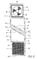
- Figure 2 is a schematic front view of the preferred embodiment of an air-conditioning apparatus according to the present invention;
- Figure 3 is a sectional side view of the preferred embodiment;
- Figure 4 is a fragmentary sectional view of a condenser/evaporator of the preferred embodiment; and
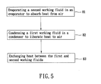
- Figure 5 is a flow chart, illustrating the steps involved in an air-conditioning method of the present invention.
- Referring to Figures 2 to 4, the preferred embodiment of an air-conditioning apparatus according to the present invention is shown to comprise a
housing 2, first and secondheat exchange units 3, 4, and first andsecond tubing units - The
housing 2 has anupper chamber 21, alower chamber 22, anupper air inlet 23 and anupper air outlet 24 both formed in a front side of thehousing 2 and both communicating with theupper chamber 21, and alower air inlet 25 and alower air outlet 26 both formed in a rear side of thehousing 2 and both communicating with thelower chamber 22. The upper air inlet andoutlet outlet - The first heat exchange unit 3 is disposed in the
upper chamber 21, and has acondenser 31 proximate to theupper air outlet 24, and afirst fan 32 disposed proximate to thecondenser 31 opposite to theupper air outlet 24. Thecondenser 31 includes a vapor-receivingsection 311 formed on a top end thereof, a liquid-receivingsection 312 formed on a bottom end thereof, and a plurality ofchannels 313 connected between the vapor-receiving and liquid-receivingsections first fan 32 is adapted to draw air from the first temperature region into theupper chamber 21 through theupper air inlet 23 for exchange of heat with thecondenser 31. - The second
heat exchange unit 4 is disposed in thelower chamber 22, and has anevaporator 41 proximate to thelower air outlet 26, and asecond fan 42 disposed proximate to theevaporator 41 opposite to thelower air outlet 26. Theevaporator 41 includes a vapor-receivingsection 411 formed on a top end thereof, a liquid-receivingsection 412 formed on a bottom end thereof, and a plurality ofchannels 413 connected between the vapor-receiving and liquid-receivingsections second fan 42 is adapted to draw air from the second temperature region into thelower chamber 22 through thelower air inlet 25 for exchange of heat with theevaporator 41. - A
thermoelectric cooler 5 is disposed between the upper andlower chambers housing 2 in an inclined manner with respect to a horizontal line, and has ahot side 53, and acold side 54 opposite to thehot side 53 and having a cooling function. Thethermoelectric cooler 5 is controlled through a circuit so as to keep thehot side 53 and thecold side 54 at constant hot and cold temperatures, respectively. - The
first tubing unit 6 is connected to thecondenser 31 to form a closed circulating path that extends downward from and that extends upward to thecondenser 31. Thefirst tubing unit 6 has a vapor-flowingtube section 62, a liquid-flowingtube section 63, and a heatexchange tube section 61 connected between the vapor-flowing and liquid-flowingtube sections exchange tube section 61 is inclined with respect to the horizontal line so that the heatexchange tube section 61 has alower end 611, and ahigher end 612 opposite to and higher than thelower end 611. The heatexchange tube section 61 is in contact with thehot side 53 of thethermoelectric cooler 5, and is disposed away from thecondenser 31. The vapor-flowingtube section 62 is connected to the vapor-receivingsection 311 of thecondenser 31 and thehigher end 612 of the heatexchange tube section 61. The liquid-flowingtube section 63 is connected to the liquid-receivingsection 312 of thecondenser 31 and thelower end 611 of the heatexchange tube section 61. - The
second tubing unit 7 is connected to theevaporator 41 to form a closed circulating path that extends downward to and that extends upward from theevaporator 41. Thesecond tubing unit 7 has a vapor-flowingtube section 72, a liquid-flowingtube section 73, and a heatexchange tube section 71 connected between the vapor-flowing and liquid-flowingtube sections exchange tube section 73 is inclined with respect to the horizontal line so that the heatexchange tube section 71 has alower end 711, and ahigher end 712 opposite to and higher than thelower end 711. The heatexchange tube section 71 is in contact with thecold side 54 of thethermoelectric cooler 5, and is disposed away from theevaporator 41. The vapor-flowingtube section 72 is connected to the vapor-receivingsection 411 of theevaporator 41 and thehigher end 712 of the heatexchange tube section 71. The liquid-flowingtube section 73 is connected to the liquid-receivingsection 412 of theevaporator 41 and thelower end 711 of the heatexchange tube section 71. Thesecond tubing unit 7 further has aninsulating layer 74 that is made of a non-heat-conductive material and that covers the heatexchange tube section 71 and the liquid-flowingtube section 73. - The
second tubing unit 7 and theevaporator 41 are disposed at a level generally lower than that of thefirst tubing unit 6 and thecondenser 31. Thethermoelectric cooler 5 is disposed at a level generally higher than thesecond tubing unit 7 and theevaporator 41 and generally lower than thefirst tubing unit 6 and thecondenser 31. - First and
second working fluids second tubing units condenser 31, and theevaporator 41 are evacuated, so that each of the first andsecond working fluids second working fluids second working fluids - Referring to Figure 5, in combination with Figures 2 and 3, an air-conditioning method that can be carried out by the air-conditioning apparatus of the present invention includes the steps of evaporating the second working
fluid 40, condensing the first workingfluid 30, and exchanging heat between the first andsecond working fluids - In
step 81, the second workingfluid 40 is circulated through the closed circulating path formed by thesecond tubing unit 7 and theevaporator 41 so as to flow upward and downward alternately. During such circulation, the second workingfluid 40, which is in a liquid state, evaporates in theevaporator 41 and absorbs heat from air that is drawn into thelower chamber 22 through thelower air inlet 25 by thesecond fan 42. The air is thus cooled and is discharged through thelower air outlet 26. During evaporation, the vaporized second workingfluid 40 flows upward along thechannels 413 from the liquid-receivingsection 412 and into the vapor-receivingsection 411, after which the second workingfluid 40 flows further upward to the heatexchange tube section 71 through the vapor-flowingtube section 72. - In
step 82, the vaporized second workingfluid 40, when reaching the heatexchange tube section 71, exchanges heat with the first workingfluid 30 through thethermoelectric cooler 5. In particular, due to the cooling function of thecold side 54 of thethermoelectric cooler 5, the vaporized workingfluid 40 in the heatexchange tube section 71 condenses and flows downward through the liquid-flowingtube section 73. Thehot side 53 of thethermoelectric cooler 5 transfers heat from the second workingfluid 40 to the heatexchange tube section 61 so that the first workingfluid 30 evaporates in the heatexchange tube section 61 and flows upward through the vapor-flowingtube section 62. - In
step 83, the first workingfluid 30 is circulated through the closed circulating path formed by thefirst tubing unit 6 and thecondenser 31 so as to flow upward and downward alternately. During circulation, the vaporized first workingfluid 30, by condensing in thecondenser 31, liberates heat to air which is drawn into theupper chamber 21 through theupper air inlet 23 by thefirst fan 32. The air becomes hot and is discharged out of theupper chamber 21 through theupper air outlet 24. During condensation, the condensed first workingfluid 30 flows downward along thechannels 313 by gravity from the vapor-receivingsection 311 into the liquid-receivingsection 312 from which the first workingfluid 30 flows further downward to the heatexchange tube section 61 through the liquid-flowingtube section 63. - It should be noted that the insulating
layer 74 of thesecond tubing unit 7 isolates the liquid-flowingtube section 73 from ambient temperature so that the liquid-state working fluid 40 in the liquid-flowingtube section 73 will not vaporize. - The advantages of the air-conditioning apparatus and method of the present invention can be summarized as follows:
- Through phase change of the first and second working
fluids fluids fluids fluids
Claims (9)
- An air-conditioning apparatus, comprising:a housing (2) including an upper chamber (21) that has an upper air inlet (23) and an upper air outlet (24), and a lower chamber (22) that has a lower air inlet (25) and a lower air outlet (26); anda first heat exchange unit (3) disposed in said upper chamber (21) and having a first working fluid (30), a condenser (31) to condense said first working fluid (30), and a first fan (32) adapted to draw air into said upper chamber (21) through said upper air inlet (23) for exchange of heat with said condenser (31);characterized by:a second heat exchange unit (4) disposed in said lower chamber (22) and having a second working fluid (40), an evaporator (41) to vaporize said second working fluid (40), and a second fan (42) adapted to draw air into said lower chamber (22) through said lower air inlet (25) for exchange of heat with said evaporator (41);a first tubing unit (6) connected to said condenser (31) to form a closed circulating path that extends downward from said condenser (31) and that extends upward to said condenser (31), said first working fluid (30) circulating through said first tubing unit (6) and said condenser (31), said first tubing unit (6) having a heat exchange tube section (61) disposed away from said condenser (31); anda second tubing unit (7) connected to said evaporator (41) to form a closed circulating path that extends downward to said evaporator (41) and that extends upward from said evaporator (41), said second working fluid (40) circulating through said second tubing unit (7) and said evaporator (41), said second tubing unit (7) having a heat exchange tube section (71) disposed away from said evaporator (41) and associated with said heat exchange tube section (61) of said first tubing unit (6) such that said second working fluid (40) transfers heat to said first working fluid (30).
- The air-conditioning apparatus of Claim 1, further characterized by a thermoelectric cooler (5) that has a cold side (54) and a hot side (53) respectively in contact with said heat exchange tube sections (71, 61) of said second and first tubing units (7, 6).
- The air-conditioning apparatus of Claim 2,
characterized in that all of said heat exchange tube sections (71, 61) of said second and first tubing units (7, 6) and said cold and hot sides (54, 53) of said thermoelectric cooler (5) are inclined with respect to a horizontal line so that each of said heat exchange tube sections (71, 61) has a lower end (711, 611), and a higher end (712, 612) opposite to and higher than said lower end (711, 611). - The air-conditioning apparatus of Claim 3,
characterized in that each of said condenser (31) and said evaporator (41) has a top end provided with a vapor-receiving section (311, 411), a bottom end provided with a liquid-receiving section (312, 412), and a plurality of channels (313, 413) connected between said vapor-receiving and liquid-receiving sections (311, 411, 312, 412). - The air-conditioning apparatus of Claim 4, characterized in that said second tubing unit (7) further has a vapor-flowing tube section (72) connected to said vapor-receiving section (411) of said evaporator (41) and said higher end (712) of said heat exchange tube section (71) of said second tubing unit (7), and a liquid-flowing tube section (73) connected to said liquid-receiving section (412) of said evaporator (41) and said lower end (711) of said heat exchange tube section (71) of said second tubing unit (7).
- The air-conditioning apparatus of Claim 5,
characterized in that said second tubing unit (7) further has an insulating layer (74) that is made of a non-heat-conductive material and that covers said heat exchange tube section (71) and said liquid-flowing tube section (73) of said second tubing unit (7). - The air-conditioning apparatus of Claim 1,
characterized in that characterized in that each of said first and second working fluids (30, 40) has a phase-change temperature of about 5-10°C. - An air-conditioning method, characterized by:(a) circulating a first working fluid (30) through a closed circulating path formed by a first tubing unit (6) and a condenser (31) to cause the first working fluid (30) to flow upward and downward alternately;(b) circulating a second working fluid (40) through a closed circulating path formed by a second tubing unit (7) and an evaporator (41) to cause the second working fluid (40) to flow upward and downward alternately, the second tubing unit (7) and the evaporator (41) being disposed at a level generally below the first tubing unit (6) and the condenser (31);(c) absorbing heat from air by evaporating the second working fluid (40) in the evaporator (41) so that the second working fluid (40) flows upward;(d) liberating heat to air by condensing the first working fluid (30) in the condenser (31) so that the first working fluid (30) flows downward; and(e) exchanging heat between the first and second working fluids (30, 40) at a level generally higher than the second tubing unit (7) and generally lower than the first tubing unit (6) so that the first working fluid (30) evaporates and flows upward and the second working fluid (40) condenses and flows downward.
- The air-conditioning method of Claim 8,
characterized in that each of said first and second working fluids (30, 40) has a phase-change temperature of about 5-10°C.
Applications Claiming Priority (1)
| Application Number | Priority Date | Filing Date | Title |
|---|---|---|---|
| CNA2006101484676A CN101182959A (en) | 2006-11-14 | 2006-11-14 | Two-phase changing temperature control device and method |
Publications (2)
| Publication Number | Publication Date |
|---|---|
| EP1923641A2 true EP1923641A2 (en) | 2008-05-21 |
| EP1923641A3 EP1923641A3 (en) | 2009-05-06 |
Family
ID=39125122
Family Applications (1)
| Application Number | Title | Priority Date | Filing Date |
|---|---|---|---|
| EP07253053A Withdrawn EP1923641A3 (en) | 2006-11-14 | 2007-08-02 | Air-conditioning apparatus and method |
Country Status (2)
| Country | Link |
|---|---|
| EP (1) | EP1923641A3 (en) |
| CN (1) | CN101182959A (en) |
Cited By (1)
| Publication number | Priority date | Publication date | Assignee | Title |
|---|---|---|---|---|
| EP2295879A1 (en) * | 2009-08-26 | 2011-03-16 | Chuan-Sheng Chen | Thermoelectric cooling chip based air conditioner |
Families Citing this family (2)
| Publication number | Priority date | Publication date | Assignee | Title |
|---|---|---|---|---|
| CN111189141A (en) * | 2018-11-15 | 2020-05-22 | 东富电器股份有限公司 | Intelligent cold and hot fan |
| CN113019667B (en) * | 2021-01-29 | 2022-06-14 | 华电电力科学研究院有限公司 | System and method for adjusting flue gas volume at coal mill inlet of fan mill pulverizing system |
Citations (10)
| Publication number | Priority date | Publication date | Assignee | Title |
|---|---|---|---|---|
| GB1050798A (en) * | 1963-10-30 | |||
| US2932953A (en) * | 1955-08-12 | 1960-04-19 | Gen Electric Co Ltd | Thermoelectric cooling units |
| US2947150A (en) * | 1958-02-21 | 1960-08-02 | Whirlpool Co | Refrigerating apparatus having improved heat transferring means |
| US3054840A (en) * | 1958-05-06 | 1962-09-18 | Westinghouse Electric Corp | Thermopile |
| US3111813A (en) * | 1958-12-04 | 1963-11-26 | Siemens Elektrogeraete Gmbh | Peltier cooling apparatus |
| GB980458A (en) * | 1960-05-17 | 1965-01-13 | Siemens Elektrogeraete Gmbh | Improvements in or relating to devices for the thermoelectric conversion of heat, the devices employing peltier elements |
| GB981419A (en) * | 1960-06-22 | 1965-01-27 | Siemens Elektrogeraete Gmbh | Improvements in or relating to thermoelectric devices |
| FR2407447A1 (en) * | 1977-10-26 | 1979-05-25 | Lutard Francois | Heat transfer system - has heat exchanger one each side of heat pump, or on one side only |
| US4718249A (en) * | 1984-04-16 | 1988-01-12 | Hanson Wallace G | Apparatus for heating and cooling |
| US20040177621A1 (en) * | 2001-04-18 | 2004-09-16 | Tsung-Chih Chen | Air conditioner temperature exchanger |
-
2006
- 2006-11-14 CN CNA2006101484676A patent/CN101182959A/en active Pending
-
2007
- 2007-08-02 EP EP07253053A patent/EP1923641A3/en not_active Withdrawn
Patent Citations (10)
| Publication number | Priority date | Publication date | Assignee | Title |
|---|---|---|---|---|
| US2932953A (en) * | 1955-08-12 | 1960-04-19 | Gen Electric Co Ltd | Thermoelectric cooling units |
| US2947150A (en) * | 1958-02-21 | 1960-08-02 | Whirlpool Co | Refrigerating apparatus having improved heat transferring means |
| US3054840A (en) * | 1958-05-06 | 1962-09-18 | Westinghouse Electric Corp | Thermopile |
| US3111813A (en) * | 1958-12-04 | 1963-11-26 | Siemens Elektrogeraete Gmbh | Peltier cooling apparatus |
| GB980458A (en) * | 1960-05-17 | 1965-01-13 | Siemens Elektrogeraete Gmbh | Improvements in or relating to devices for the thermoelectric conversion of heat, the devices employing peltier elements |
| GB981419A (en) * | 1960-06-22 | 1965-01-27 | Siemens Elektrogeraete Gmbh | Improvements in or relating to thermoelectric devices |
| GB1050798A (en) * | 1963-10-30 | |||
| FR2407447A1 (en) * | 1977-10-26 | 1979-05-25 | Lutard Francois | Heat transfer system - has heat exchanger one each side of heat pump, or on one side only |
| US4718249A (en) * | 1984-04-16 | 1988-01-12 | Hanson Wallace G | Apparatus for heating and cooling |
| US20040177621A1 (en) * | 2001-04-18 | 2004-09-16 | Tsung-Chih Chen | Air conditioner temperature exchanger |
Cited By (1)
| Publication number | Priority date | Publication date | Assignee | Title |
|---|---|---|---|---|
| EP2295879A1 (en) * | 2009-08-26 | 2011-03-16 | Chuan-Sheng Chen | Thermoelectric cooling chip based air conditioner |
Also Published As
| Publication number | Publication date |
|---|---|
| CN101182959A (en) | 2008-05-21 |
| EP1923641A3 (en) | 2009-05-06 |
Similar Documents
| Publication | Publication Date | Title |
|---|---|---|
| JP7137555B2 (en) | Active/passive cooling system | |
| JP4318567B2 (en) | Cooling system | |
| JP6008206B2 (en) | Refrigeration cycle equipment | |
| JP4084153B2 (en) | Condensation prevention device for refrigerator | |
| CN103528308B (en) | Refrigerator | |
| CN107218745A (en) | Heat exchanger and the method for manufacturing heat exchanger | |
| US20100242534A1 (en) | Hybrid cascade vapor compression regrigeration system | |
| KR20140022919A (en) | Combined binary refrigeration cycle apparatus | |
| JP2017138090A (en) | Refrigeration cycle device | |
| WO2013108637A1 (en) | Refrigeration-cycle apparatus | |
| JP2005326138A (en) | Cooling device and vending machine with it | |
| JP2005172329A (en) | Cooling storage | |
| US20100018224A1 (en) | Stirling cooler | |
| JP5034435B2 (en) | vending machine | |
| US20080104964A1 (en) | Air-conditioning apparatus and method | |
| EP1923641A2 (en) | Air-conditioning apparatus and method | |
| KR100666920B1 (en) | Heat exchanging device | |
| KR101122725B1 (en) | Heat pump type cooling and heating apparatus | |
| KR20020014609A (en) | Air conditioner | |
| KR100426834B1 (en) | Heat Absorbing System for Absorber, Condenser and Evaporator by Using Latent Heat of Phase-change Fluids in Absorption Heat Pump | |
| KR100625751B1 (en) | Air-conditioner for cooling and heating | |
| JP5793715B2 (en) | Air conditioner | |
| KR20200001250A (en) | heating and cooling system of building using an electric apparatus | |
| EP4206562A1 (en) | A cooling device | |
| JP2012180980A (en) | Air conditioner |
Legal Events
| Date | Code | Title | Description |
|---|---|---|---|
| PUAI | Public reference made under article 153(3) epc to a published international application that has entered the european phase |
Free format text: ORIGINAL CODE: 0009012 |
|
| AK | Designated contracting states |
Kind code of ref document: A2 Designated state(s): AT BE BG CH CY CZ DE DK EE ES FI FR GB GR HU IE IS IT LI LT LU LV MC MT NL PL PT RO SE SI SK TR |
|
| AX | Request for extension of the european patent |
Extension state: AL BA HR MK RS |
|
| PUAL | Search report despatched |
Free format text: ORIGINAL CODE: 0009013 |
|
| AK | Designated contracting states |
Kind code of ref document: A3 Designated state(s): AT BE BG CH CY CZ DE DK EE ES FI FR GB GR HU IE IS IT LI LT LU LV MC MT NL PL PT RO SE SI SK TR |
|
| AX | Request for extension of the european patent |
Extension state: AL BA HR MK RS |
|
| AKX | Designation fees paid | ||
| REG | Reference to a national code |
Ref country code: DE Ref legal event code: 8566 |
|
| STAA | Information on the status of an ep patent application or granted ep patent |
Free format text: STATUS: THE APPLICATION IS DEEMED TO BE WITHDRAWN |
|
| 18D | Application deemed to be withdrawn |
Effective date: 20091107 |