EP1922905B1 - Digitally controlled luminaire system - Google Patents
Digitally controlled luminaire system Download PDFInfo
- Publication number
- EP1922905B1 EP1922905B1 EP05820993A EP05820993A EP1922905B1 EP 1922905 B1 EP1922905 B1 EP 1922905B1 EP 05820993 A EP05820993 A EP 05820993A EP 05820993 A EP05820993 A EP 05820993A EP 1922905 B1 EP1922905 B1 EP 1922905B1
- Authority
- EP
- European Patent Office
- Prior art keywords
- light
- emitting elements
- arrays
- temperature
- optical
- Prior art date
- Legal status (The legal status is an assumption and is not a legal conclusion. Google has not performed a legal analysis and makes no representation as to the accuracy of the status listed.)
- Not-in-force
Links
Images

Classifications
-
- H—ELECTRICITY
- H05—ELECTRIC TECHNIQUES NOT OTHERWISE PROVIDED FOR
- H05B—ELECTRIC HEATING; ELECTRIC LIGHT SOURCES NOT OTHERWISE PROVIDED FOR; CIRCUIT ARRANGEMENTS FOR ELECTRIC LIGHT SOURCES, IN GENERAL
- H05B45/00—Circuit arrangements for operating light-emitting diodes [LED]
- H05B45/20—Controlling the colour of the light
- H05B45/22—Controlling the colour of the light using optical feedback
-
- H—ELECTRICITY
- H05—ELECTRIC TECHNIQUES NOT OTHERWISE PROVIDED FOR
- H05B—ELECTRIC HEATING; ELECTRIC LIGHT SOURCES NOT OTHERWISE PROVIDED FOR; CIRCUIT ARRANGEMENTS FOR ELECTRIC LIGHT SOURCES, IN GENERAL
- H05B45/00—Circuit arrangements for operating light-emitting diodes [LED]
- H05B45/20—Controlling the colour of the light
- H05B45/28—Controlling the colour of the light using temperature feedback
-
- Y—GENERAL TAGGING OF NEW TECHNOLOGICAL DEVELOPMENTS; GENERAL TAGGING OF CROSS-SECTIONAL TECHNOLOGIES SPANNING OVER SEVERAL SECTIONS OF THE IPC; TECHNICAL SUBJECTS COVERED BY FORMER USPC CROSS-REFERENCE ART COLLECTIONS [XRACs] AND DIGESTS
- Y10—TECHNICAL SUBJECTS COVERED BY FORMER USPC
- Y10S—TECHNICAL SUBJECTS COVERED BY FORMER USPC CROSS-REFERENCE ART COLLECTIONS [XRACs] AND DIGESTS
- Y10S362/00—Illumination
- Y10S362/80—Light emitting diode
Abstract
Description
- The present invention pertains to luminaires, and particularly to a luminaire system capable of maintaining desired lighting conditions, for example constant colour temperature, during operation.
- Recent technological advancements in light-emitting diode (LED) design have been a boon to the lighting industry. With their high overall luminous efficacy and flexibility for achieving various light patterns, LED-based luminaires are increasingly being used in signage, advertising, display lighting, and backlit lighting applications. LED-based luminaires are also replacing the traditional incandescent or fluorescent lighting fixtures to become the mainstream lighting architecture.
- Due to its natural lighting characteristics, white light is the preferred choice for lighting. An important consideration for LED-based luminaires used for ambient lighting is the need to produce natural white light. White light can be generated by mixing the light emitted from different colour LEDs.
- Various standards have been proposed to characterize the spectral content of light. One way to characterize light emitted by a test light source is to compare it with the light radiated by a black body and identify the temperature of the black body at which its perceived colour best matches the perceived colour of the test light source. That temperature is called correlated colour temperature (CCT) and is usually measured in Kelvin (K). The higher the CCT, the bluer, or cooler the light appears. The lower the CCT, the redder, or warmer the light appears. An incandescent light bulb has a CCT of approximately 2854 K, and fluorescent lamps can have CCTs in the range of approximately 3200K to 6500 K.
- Furthermore the properties of light can be characterized in terms of luminous flux and chromaticity. Luminous flux is used to define the measurable amount of light and chromaticity is used to define the perceived colour impression of light, irrespective of its perceived brightness. Chromaticity and luminous flux are measured in units according to standards of the Commission Internationale de l'Eclairage (CIE). The CIE chromaticity standards define hue and saturation of light based on chromaticity coordinates that specify a position in a chromaticity diagram. The chromaticity coordinates of light are derived from tristimulus values and expressed by the ratio of the tristimulus values to their sum; i.e. x=X/(X+Y+Z), y=Y/(X+Y+Z), z=Z/(X+Y+Z), where x, y and z are the chromaticity coordinates and X, Y, and Z the tristimulus values. Because x+y+z=1, it is only necessary to specify two chromaticity coordinates such as x and y, for example. Any CCT value can be transformed into corresponding chromaticity coordinates.
- In spite of their success, LED-based luminaires can be affected by a number of parameters in a complex way. Chromaticity and luminous flux output of LEDs can greatly depend on junction temperature and drive current as well as device aging effects that result in efficacy degradation over time, which can have undesirable effects on the CCT and more generally the chromaticity of the emitted light.
- Ignoring temperature dependencies, the amount of light emitted by an LED is proportional to its instantaneous forward current. If the LEDs are pulsed at a rate greater than about 300 Hz, the human visual system perceives a time-averaged amount of light as opposed to individual pulses. As a result, luminaire dimming can be achieved by varying the amount of time-averaged forward current, using such techniques as pulse width modulation (PWM) or pulse code modulation (PCM). However, changes in the average forward current can affect the junction temperature of the LED, which can alter the spectral power distribution and in consequence the CCT or chromaticity and luminous flux of the light emitted by the LED. The compensation of this effect can become complex when various coloured LEDs are used to generate mixed light of a desired chromaticity. As discussed by M. Dyble, in "Impact of Dimming White LEDs: Chromaticity Shifts Due to Different Dimming Methods," Fifth International Conference on Solid State Lighting, Bellingham, WA; SPIE Vol. 5941, 2005, colour appearance of the resultant mixed light can shift unacceptably when dimming, as the spectral power distribution of the individual LEDs can change.
- LED junction temperature variations can also cause undesired effects on the spectral power distribution of the resultant output light. Variations in junction temperature not only can reduce the luminous flux output, but can also cause undesirable variations in the CCT of the mixed light. Overheating can also reduce the life span of LEDs.
- In order to overcome these limitations, various methods for generating natural white light have been proposed.
U.S. Patent No. 6,448,550 to Nishimura teaches a solid-state illumination device having a plurality of LEDs of different colours using optical feedback. Light from the LEDs is measured by photosensitive sensors mounted in close proximity with LEDs and compared with a reference set of responses to a previously measured spectral power distribution. The amount of variation between the sensor responses to the light from the LEDs and the previously measured spectral power distribution is used as a basis for adjusting the current to the LEDs in order to maintain the light from the LEDs as close as possible to the pre-determined spectral power distribution. While the Nishimura reference provides an effective way to achieve control of the spectral power distribution of the output light with any desired colour property, it does not consider maintaining colour stability over the life of the LEDs and at different operating conditions, including dimming. -
U.S. Patent No. 6,507,159 to Muthu discloses a control method and system for an LED-based luminaire having a plurality of red, green and blue light LEDs for generating a desired light by colour mixing. Muthu seeks to alleviate the unwanted variations in the luminous flux output and CCT of the desired light by providing a control system with a feedback system including filtered photodiodes, a mathematical transformation for determining tristimulus values of the LEDs, and a reference-tracking controller for resolving the difference between the feedback tristimulus values and the desired reference tristimulus values in order to adjust the forward current of the LEDs, such that the difference in tristimulus values is reduced to zero. The Muthu reference however does not provide a solution for alleviating the discrepancies in the colour temperature of the desired light that are caused by the shifting of peak wavelength of the LEDs over time. In addition, the calculations required for the mathematical transformation make it difficult to implement a feedback control system with a response time that is fast enough to avoid visual flicker during dimming operations, for example. -
U.S. Patent No. 6,576,881 to Muthu et al. discloses a method and system for controlling the output light generated by red, green, and blue LEDs. Sensors positioned proximate to the LEDs to detect a first set of approximate tristimulus values of the output light. The first set of tristimulus values is communicated to a controller, which converts these values into a second set of tristimulus values representative of a standard colourimetric system. The relative luminous flux output of the LEDs is adjusted on the basis of the difference between the second set of the tristimulus values and a set of user-specified tristimulus values. The Muthu et al. reference however does not account for shifting of the peak wavelength of the LEDs due to temperature, dimming, or age of the components. In addition, the calculations required for the mathematical transformation between the two sets of tristimulus values makes it difficult to implement a feedback control system with a response time that is fast enough to avoid visual flicker during dimming operations, for example. -
U.S. Patent No. 6,630,801 to Schuurmans provides a method and system for sensing the colour point of resultant light produced by mixing coloured light from a plurality of LEDs in the RGB colours. The system comprises a feedback unit for generating feedback values corresponding to the chromaticity of the resultant light based on values obtained from filtered and unfiltered photodiodes that are responsive to the light from the LEDs, as well as a controller which adjusts the resultant light based upon the difference between the feedback values and values representative of the chromaticity of a desired resultant light. However, the method disclosed by Schuurmans does not account for shifting of the peak wavelength of the LEDs due to temperature, dimming, or age of the components. -
U.S. Patent Publication No. 2003/0230991 to Muthu et al. discloses an LED-based white-light backlighting system for electronic displays. The backlighting of Muthu et al. includes a plurality of LEDs of different light colours arranged such that the combination of light colours produces white light, and a microprocessor which monitors the luminous flux, radiant flux, or tristimulus levels of the white light and controls the luminous flux and chromaticity of the white light by feedback control. The backlighting of Muthu et al. uses photodiodes with filters to determine approximate tristimulus values of the LEDs and adjust the luminous flux and chromaticity of the white light. Temperature variations from heat sinks attached to LEDs is also measured and used to account for changes in the luminous flux and chromaticity of the LEDs. Muthu et al. et al. also fail to consider the effect of peak wavelength shift and photodiode inaccuracies on the white light produced. -
U.S. Patent No. 6,441,558 also to Muthu et al. discloses a multi-colour LED-based luminaire for generating various desired light at different colour temperatures. The desired luminous flux output for each array of colour LEDs is achieved by a controller system that adjusts the current supplied to the LEDs based on the chromaticity of the desired light and the junction temperature of the LEDs. One of the shortcomings associated with the LED-based luminaire of Muthu et al. is that in order to measure the luminous flux of an array of LEDs, an optical feedback sensor is used to obtain the luminous flux from the LEDs which is communicated to the controller by a polling sequence. According to Muthu et al., the measurement sequence begins by measuring the luminous flux output of the all LED arrays in operation. Each array of LEDs is alternately switched "OFF" briefly, and a further measurement is taken. The difference between the initial measurement and the next measurement provides the light output from the LED array that was turned off. The measurement of the light output is repeated for the remaining LED arrays. A drawback of this procedure as disclosed by Muthu et al. is the excessive amount of thermal stress imposed on the LEDs during ON and OFF cycles at low frequencies. -
WO02/47438 -
WO02/076150 -
US2005/0002019 describes a drive device for a light-emitting component wherein a photo detector detects the light output from the light-emitting component, and the drive device regulates the drive of the light-emitting component based on the detected light output, a temperature at the photo detector and a desired light output. -
US2002/0179816 describes a LED control device comprising LED light sources and a controller for adjustment of the light output from the light sources. The controller receives signals for optical feedback, ambient temperature compensation and detection of short term current changes. -
WO2006/056066 describes a lighting module comprising light-emitting elements and a drive and control system. The module further comprises a feedback system for optical feedback of the light output of the light-emitting elements and the operational temperature of the optical sensors. - There is therefore a need for a system and method that can effectively maintain the chromaticity, colour temperature and luminous flux of a multi-colour LED-based luminaire, while alleviating the effects of device aging and junction temperature changes on the LEDs.
- This background information is provided to reveal information believed by the applicant to be of possible relevance to the present invention. No admission is necessarily intended, nor should be construed, that any of the preceding information constitutes prior art against the present invention.
- An object of the present invention is to provide a digitally controlled luminaire system. In accordance with one aspect of the present invention there is provided a luminaire system as defined in
claim 1. In accordance with another aspect of the present invention there is provided a method for controlling the operation of one or more arrays in a luminaire system as defined inclaim 7. - A better understanding of the embodiments of the present invention can be obtained with reference to the following drawings which show by way of example embodiments of the present invention, in which:
-
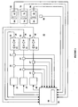
Figure 1 is a block diagram of a light-emitting element luminaire according to one embodiment of the present invention. -
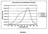
Figure 2 is a graphical representation showing the red LED spectra during full light output and during reduced light output in relation to the spectral radiant flux response of a red sensor. -
Figure 3 is a flow chart showing the sequence of steps involved in the control process of a controller according to an embodiment of the present invention. - The term "light-emitting element" is used to define any device that emits radiation in any region or combination of regions of the electromagnetic spectrum for example, the visible region, infrared and/or ultraviolet region, when activated by applying a potential difference across it or passing a current through it, for example. Therefore a light-emitting element can have monochromatic, quasimonochromatic, polychromatic or broadband spectral emission characteristics. Examples of light-emitting elements include semiconductor, organic, or polymer/polymeric light-emitting diodes, blue or UV pumped phosphor coated light-emitting diodes, optically pumped nanocrystal light-emitting diodes or any other similar light-emitting devices as would be readily understood by a worker skilled in the art. Furthermore, the term light-emitting element is used to define the specific device that emits the radiation, for example a LED die, and can equally be used to define a combination of the specific device that emits the radiation together with a housing or package within which the specific device or devices are placed.
- The term "output light" is used to define electromagnetic radiation of a particular frequency or range of frequencies in any region of the electromagnetic spectrum for example, the visible, infrared and ultraviolet regions, or any combination of regions of the electromagnetic spectrum, generated by a one or more of light-emitting elements.
- The term "luminous flux" is used to define the amount of light emitted by a light source according to standards of the Commission Internationale de l'Eclairage (CIE). Where the wavelength regime of interest includes infrared and/or ultraviolet wavelengths, the term "luminous flux" is used to include radiant flux as defined by CIE standards.
- The term "spectral radiant flux" is used to define the quantity of radiant flux per unit wavelength at each wavelength emitted by a light source according to CIE standards.
- The term "spectral power distribution" is used to refer to the wavelength dependency of the differential amount of radiant flux per differential wavelength within a region of interest of the electromagnetic spectrum.
- The term "chromaticity" is used to define the perceived colour impression of light according to CIE standards.
- The term "sensor" is used to define a device having a measurable sensor parameter in response to a physical quantity, including temperature, chromaticity or luminous flux.
- The term "controller" is used to define a computing device or microcontroller having a central processing unit (CPU) and peripheral input/output devices (such as A/D or D/A converters) to monitor parameters from peripheral devices that are operatively coupled to the controller. These input/output devices can also permit the CPU to communicate and control peripheral devices that are operatively coupled to the controller. The controller can optionally include one or more storage media collectively referred to herein as "memory". The memory can be volatile and non-volatile computer memory such as RAM, PROM, EPROM, and EEPROM, floppy disks, compact disks, optical disks, magnetic tape, or the like, wherein control programs (such as software, microcode or firmware) for monitoring or controlling the devices coupled to the controller are stored and executed by the CPU. Optionally, the controller also provides the means of converting user-specified operating conditions into control signals to control the peripheral devices coupled to the controller. The controller can receive user-specified commands by way of a user interface, for example, a keyboard, a touchpad, a touch screen, a console, a visual or acoustic input device as is well known to those skilled in this art.
- The term "substrate" is used to define a thermally conductive material with which a light-emitting element is in thermal contact and capable of transferring heat generated by the light-emitting element thereto.
- As used herein, the term "about" refers to a +/-10% variation from the nominal value. It is to be understood that such a variation is always included in any given value provided herein, whether or not it is specifically identified.
- Unless defined otherwise, all technical and scientific terms used herein have the same meaning as commonly understood by one of ordinary skill in the art to which this invention belongs.
- The present invention provides and method and apparatus for compensating for chromaticity or CCT drift for multi-colour light-emitting element-based luminaires irrespective of the luminous flux output. The luminous flux output of luminaires can be affected by changes in the spectral power distribution of the output light of the individual light-emitting elements in the luminaire due to variations in temperature, as for example caused by varying operating conditions, time-averaged or instantaneous peak current, and device aging. This effect can become problematic in feedback controlled light-emitting element-based luminaires, since the changes to the spectral power distribution of the output light can affect the sensor readings from the feedback sensors, which in turn can cause the feedback controller to enhance undesired effects of the drift. The present invention can alleviate these problems by considering one or more of the following: heat sink temperature, substrate temperature, instantaneous forward current and time-averaged forward current. Based on these parameters, as well as empirical characteristics of the sensors and the light-emitting elements, a feedback controller can make adjustments to drive currents in order to substantially maintain the output light of the luminaire at the desired chromaticity or CCT.
- The present invention provides a luminaire system capable of generating light of a desired chromaticity and luminous flux output during continuous operation with varying ambient operating temperature. The luminaire system can be further capable of maintaining a desired correlated colour temperature during dimming of the luminaire. The luminaire system comprises one or more arrays of light-emitting elements for generating light. A current driver system is coupled to the arrays and can selectively supply electrical drive current to each of the arrays, wherein the current driver system is responsive to drive signals received from a controller. The luminaire system further comprises an optical sensor system which captures a predetermined portion of the generated light and generates optical signals representative of chromaticity and luminous flux output of the predetermined portion of the light. A heat sensing system is operatively coupled to the one or more arrays and provides a means for generating signals representative of the junction temperatures of arrays of light-emitting elements during operation. The luminaire system further comprises a controller that is operatively connected to the current driver system, the optical sensor system and the heat sensing system for receiving the signals generated by each of these systems. The controller is configured to generate one or more drive signals for transmission to the current driver system in response to the optical signals and thermal signals received from the optical system and the heat sensing system, respectively. The controller is thereby enabled to modify the light emitted by the arrays of light-emitting elements having specific regard to current light output, desired light output and the variations in light output from the arrays of light-emitting elements based on junction temperature thereof.
-
Figure 1 illustrates a block diagram of a light-emitting element luminaire according to an embodiment of the present invention. Theluminaire 10 includesarrays elements 22, green light-emittingelements 32, and blue light-emittingelements 42 inarrays elements 22, green light-emittingelements 32 and blue light-emittingelements 42 can generate light of a specific chromaticity, for instance white light. In one embodiment, theluminaire 10 includes mixing optics (not shown) to spatially homogenize the output light generated by mixing light from the red light-emittingelements 22, green light-emittingelements 32, and blue light-emittingelements 42. -
Current drivers arrays elements 22, green light-emittingelements 32, and blue light-emittingelements 42 inarrays current drivers elements 22, green light-emittingelements 32, and blue light-emittingelements 42 by regulating the flow of current through the red light-emittingelements 22, green light-emittingelements 32, and blue light-emittingelements 42. Thecurrent drivers arrays - In an embodiment of the present invention the
current drivers elements 22, green light-emittingelements 32, and blue light-emittingelements 42. Since the average output current to the red light-emittingelements 22, green light-emittingelements 32, or blue light-emittingelements 42 is proportional to the duty factor of the PWM control signal, it is possible to dim the output light generated by the red light-emittingelements 22, green light-emittingelements 32, or blue light-emittingelements 42 by adjusting the duty factors for eacharray elements 22, green light-emittingelements 32, or blue light-emittingelements 42 can be chosen such that the human eye perceives the light output as being constant rather than a series of light pulses, for example a frequency greater than about 60Hz for example. In an alternative embodiment, thecurrent drivers -
Current sensors current drivers element arrays current sensors array arrays - A
controller 50 is coupled tocurrent drivers controller 50 is configured to independently adjust the amount of average forward current by adjusting the duty cycle of thecurrent drivers controller 50 can also be coupled tocurrent sensors arrays current drivers - In one embodiment,
voltage sensors current drivers element arrays Controller 50 is coupled tovoltage sensors element arrays - The
luminaire 10 further includesoptical sensor systems PID controller 90 that can be embedded incontroller 50 in firmware. Alternatively, thePID controller 90 can be a separate component operatively connected to thecontroller 50. A particular advantage of this configuration is that unlike the prior art, it is unnecessary to perform mathematical operations to convert between sets of tristimulus values. Consequently, the feedback loop can be implemented so as to have a fast response time that prevents the appearance of visual flicker, for example during dimming operations. - Each
optical sensor system arrays optical sensor system optical sensors arrays optical sensor optical sensors elements 22, green light-emittingelements 32 and blue light-emittingelements 42, respectively. - Since it is often desirable to detect the luminous flux output from the luminaire in a manner similar to that perceived by the human eye, in one embodiment the
optical sensor systems arrays optical sensor filter optical filters controller 50. The optical filters 64, 74, and 84 can be thin film interference, dyed plastic, dyed glass or the like. It is understood that a number of types of optical sensors can be used, for example photodiodes, phototransistors, photosensor integrated circuits (ICs), unenergized LEDs, and the like. - Variations in the ambient operating temperature can affect the output signal of
optical sensor systems optical sensors temperature sensor 86 for sensing the operating temperature of theoptical sensor systems optical sensor arrays controller 50 which can be configured with the polynomial coefficients to process the optical signals and compensate the respective drive currents for varying temperature operating conditions of theoptical sensors - In one embodiment, higher-order polynomial equations can be used to model the parametric temperature dependency of the optical sensors as would be readily understood by those skilled in the art. Evaluation of the polynomial equations can be performed by the
controller 50. To calibrate the luminaire control system, for example the controller, the equation coefficients can be determined by computer simulation of a model luminaire or by experimental acquisition of empirical data of a luminaire and subsequently stored in memory of thecontroller 50. Alternatively, the equation can be pre-calculated and the results stored in a look-up table in the memory of thecontroller 50. The coefficients can be different for eachoptical sensor system optical sensors optical sensor optional filters optical sensor - Ideal filters can completely suppress the transmission of light outside a certain wavelength regime while not attenuating transmitted light of wavelengths within this regime. However, physically-realizable
optical filters filters Figure 2 illustrates the optical response of a red LED photodiode having a filter. As shown, the spectral power distribution of the red light generated by red LEDs can change during dimming. Due to the wavelength-dependent transmittance of the red filter, the output of the optical sensor will change, even though the integrated spectral radiant flux of the red light remains constant. In addition, theoptical sensors physical filters - Another concern in maintaining constant luminous flux and chromaticity of the output light is the peak wavelength shift caused by variations in the junction temperature of the red light-emitting
elements 22, green light-emittingelements 32 and blue light-emittingelements 42. This effect is exemplified inFigure 2 , which illustrates that there is a shift in spectral power distributions of the red light generated by a red LED between full intensity and dimmed operation, which corresponds to a change in luminous flux output. As the junction temperature increases, the peak wavelength of the luminous flux emitted by a light-emitting element can shift. In consequence, the shift in the peak wavelength due to junction temperature variations can be different for each of the red light-emittingelements 22, green light-emittingelements 32, and blue light-emittingelements 42. For instance, it is known that light generated by red LEDs undergoes the largest temperature dependent peak wavelength shift at about 0.15 nm per degree Celsius, while light emitted by green LEDs or blue LEDs shifts significantly less under the same thermal operating conditions. In addition, the luminous flux output of red LEDs based on AlInGaP technology is nonlinearly dependent on the junction temperature, while the luminous flux output of green and blue LEDs based on InGaN technology is linearly dependent. As a result, the junction temperature of the red light-emittingelements 22, green light-emittingelements 32 and blue light-emittingelements 42 can be monitored, constantly or at a predetermined or varying interval and a shift in the peak wavelengths of the emitted light can be accounted for by adjusting the target optical sensor response values to maintain the desired chromaticity or CCT of the combined light, independent of whether the luminous flux output is constant or varying due to dimming. In one embodiment each equation coefficient can account for the foregoing effects and can be expressed as a function of measured input variables such as temperature, spectral radiant flux, and luminous flux output, for example. - One or
more temperature sensors controller 50 can be provided to measure the temperature of thearrays arrays elements 22, green light-emittingelements 32 and blue light-emittingelements 42. In the presently described embodiment, junction temperature of the red light-emittingelements 22, green light-emittingelements 32 and blue light-emittingelements 42 is estimated by interpolation based on a thermal model of the light-emitting element. The thermal behaviour of the light-emitting element can be dependent upon the inherent characteristics of the particular light-emitting element employed, such as the material used, size, packaging, etc. Consequently, in one embodiment the equation coefficients can functionally depend on the junction temperatures for the red light-emittingelements 22, green light-emittingelements 32 and blue light-emittingelements 42. The polynomial-based correction can be implemented in thecontroller 50 to account for the junction temperature. The temperature dependence of the equation coefficients can be determined based on mathematical interpolation of the junction temperatures of the red light-emittingelements 22, green light-emittingelements 32 and blue light-emittingelements 42, or by other similar methods otherwise known in the art. - In one embodiment, red light-emitting
elements 22, green light-emittingelements 32, and blue light-emittingelements 42 can be mounted on separate heat sinks with separate temperature sensors thermally connected thereto. It is understood that the red light-emittingelements 22, green light-emittingelements 32, and blue light-emittingelements 42 can also be mounted on a single heat sink, whereby at least one temperature sensor would be needed to determine the junction temperature of the red light-emittingelements 22, green light-emittingelements 32, and blue light-emittingelements 42. In another embodiment of the present invention, thetemperature sensors element array elements 22, green light-emittingelements 32 and blue light-emittingelements 42, respectively. It is noted that the red light-emittingelements 22, green light-emittingelements 32 and blue light-emittingelements 42 are likely pulsed at a rate much higher than the thermal time constant of the one or more heat sinks and therefore thetemperature sensor - In one
embodiment temperature sensors - In one embodiment of the present invention,
voltage sensors controller 50 to measure the forward voltage of thearrays arrays elements 22, green light-emittingelements 32 and blue light-emittingelements 42. The equation coefficients can functionally depend on the forward voltage or the estimated values of the junction temperatures for the red light-emittingelements 22, green light-emittingelements 32 and blue light-emittingelements 42 and implemented in thecontroller 50 to monitor junction temperature variations. - It has been observed that the amount of forward current supplied to the
arrays elements 22, green light-emittingelements 32 and blue light-emittingelements 42. The effect of the forward current can become an important consideration in luminaires using PWM or PCM to control the luminous flux output. For example, in order to reduce the effect of the forward current-induced wavelength variations, the instantaneous forward current of the red light-emittingelements 22, green light-emittingelements 32 and blue light-emittingelements 42 can be kept at a constant level during the ON cycle. However, as the duty cycle and the average forward current are varied, the difference between the junction temperature of the red light-emittingelements 22, green light-emittingelements 32 and blue light-emittingelements 42 and the temperature at the one or more heat sinks increases with increasing duty cycle. As a result, the temperature measured by the one or more heat sinks bytemperature sensors elements 22, green light-emittingelements 32 and blue light-emittingelements 42. The temperatures at one or more heat sinks may remain relatively constant due to the longer thermal time constant of a heat sink, while the junction temperatures of the red light-emittingelements 22, green light-emittingelements 32 and blue light-emittingelements 42 will typically change in relation to variations in the forward current. More generally, any sudden change in forward current will cause a sudden change in the temperature of the light-emitting element junction that will exponentially equilibrate to a new steady-state temperature as the light-emitting element substrate, package, and heat sink approach thermal equilibrium, for example. - This junction temperature change of the red light-emitting
elements 22, green light-emittingelements 32 and blue light-emittingelements 42 can cause a spectral shift in the peak wavelength of light generated by each of the red light-emittingelements 22, green light-emittingelements 32 and blue light-emittingelements 42 which may not be accounted for bytemperature sensors luminaire 10. This polynomial-based correction can be used by thecontroller 50 to compensate for wavelength deviations when varying the duty cycle and subsequently the average forward current tocurrent drivers - In one embodiment, a polynomial-based correction relating to peak wavelength shift due to variations in the average forward current can be determined by measuring the spectral radiant flux output at
luminaire 10 at full luminous flux output, and subsequent measurements of the spectral radiant flux output with theluminaire 10 dimmed to one or more levels. The target optical sensor response level can be adjusted with a polynomial-based correction for each colour from the red light-emittingelements 22, green light-emittingelements 32 and blue light-emittingelements 42 to ensure that the combined light output has the same desired chromaticity. Alternatively, equation coefficients can optionally be derived from empirical data. - In another embodiment, the junction temperature for each
array element arrays 
where: ΔT is the temperature difference between the heat sink and junction in °C; θR is the thermal resistance (°C/W); and Q is the heat load (W). This factor can then be calculated bycontroller 50 to compensate for peak wavelength shift due to junction temperature instead of two separate factors based on the heat sink temperatures and forward current. - In another embodiment the junction temperature for each
array element array elements 22, green light-emittingelements 32 and blue light-emittingelements 42 can therefore be determined. A corresponding polynomial-based correction can then determined bycontroller 50 to compensate for peak wavelength shift due to junction temperature instead of two separate polynomial-based temperature corrections, one relating to heat sink temperature and the other to forward current. - In another embodiment of the invention, the junction temperature for each
array voltage sensor controller 50 to compensate for peak wavelength shift due to junction temperature. - Reference is now made to
Figure 3 , which shows a sequence of steps for the control process performed by thecontroller 50 in accordance with one embodiment of the present invention. Once theluminaire 10 is turned on in Step S1, the user preference for colour temperature or more generally chromaticity and luminous flux output or dimming level are input tocontroller 50 in Step S2 and Step S3, respectively. Information relating to characteristics of the red light-emittingelements 22, green light-emittingelements 32 and blue light-emittingelements 42, characteristics oftemperature sensors optical sensors controller 50 at Step S4 either at startup or during calibration. At Step S5, thecontroller 50 obtains the colour temperature and dimming level input by the user in Steps S2 and S3. - During Step S6, the
controller 50 monitors and obtains the spectral radiant flux measured byoptical sensors filters temperature sensors voltage sensors current drivers arrays current sensors optical sensors - Once the target response for the
optical sensors PID controller 90 in the PID loop configuration withcontroller 50. The error inputs to the PID loop are based on target and measured optical sensor responses. At Step S9, thecontroller 50 adjusts the duty cycle of the PWM control signal forcurrent drivers PID controller 50. InStep 9. Thecontroller 50 waits for a predetermined time in order to allow the feedback loop to make the appropriate adjustments, then returns to Step S5.
Claims (9)
- A luminaire system (10) for generating light of a desired chromaticity and luminous flux output, the luminaire system comprising:(a) one or more arrays (20, 30, 40), each array comprising one or more light-emitting elements (22, 32, 42) for generating light; the one or more arrays being in thermal contact with one or more heat sinks;(b) a current driver system (28, 38, 48) operatively coupled to the one or more arrays (20, 30, 40), the current driver system for selectively supplying electrical drive current to each of the one or more arrays, the current driver system being responsive to one or more drive signals;(c) one or more optical sensor systems (60, 70, 80) operatively coupled to the one or more light-emitting elements (22, 32, 42), each optical sensor system comprising one or more optical sensors (62, 72, 82) for sensing a predetermined portion of the light generated by the light-emitting elements, each optical sensor system (60, 70, 80) configured to generate optical signals representative of chromaticity and luminous flux output of the predetermined portion of the light;(d) a heat sensing system operatively coupled to the one or more arrays, the heat sensing system comprising one or more temperature sensors (26, 36, 46) in thermal contact with the one or more heat sinks, for measuring temperature signals representative of a first value of the junction temperature of each of the one or more light-emitting elements (22, 32, 42); and(e) a controller (50) operatively connected to the current driver system (28, 38, 48), the one or more optical sensor systems (60, 70, 80) and the heat sensing system; the controller (50) being configured to generate the one or more drive signals based on said optical signals and on the desired chromaticity and luminous flux output and wherein the luminaire system (10) is adapted for connection to a source of power,characterized in that
the heat sensing system further comprises a voltage sensing system including one or more voltage sensors (27, 37, 47) for measuring forward voltage signals representative of the forward voltage to one or more of the arrays (20, 30, 40);
the controller (50) is further configured to evaluate a second value of the junction temperature of the one or more light-emitting elements (22, 32, 42) based on the forward voltage signals;
the controller is configured to evaluate a first modification factor defined by a relationship between the first value of the junction temperature and the light emission characteristics of the one or more light-emitting elements, wherein the first modification factor is one or more polynomial equations;
the controller is configured to evaluate a third modification factor defined by a relationship between the second value of the junction temperature and the light emission characteristics of the one or more light-emitting elements, wherein the third modification factor is one or more polynomial equations;
the controller is configured to modify the one or more drive signals based on the first modification factor thereby compensating for temperature variations of the arrays and on the third modification factor thereby compensating for peak wavelength shift due to variations in the forward current of the arrays. - The luminaire system according to claim 1, wherein the heat sensing system is further operatively coupled to the one or more optical sensor systems (60, 70, 80), the heat sensing system further measuring temperature signals representative of the operational temperature of the one or more optical sensor systems, the controller (50) being further configured to evaluate a second modification factor defined by a relationship between the operational temperature and the optical signals from the one or more optical sensor systems, wherein the second modification factor is one or more polynomial equations; and the controller (50) being further configured to modify the one or more drive signals based on the second modification factor.
- The luminaire system according to claim 1, further comprising a current sensor system (29, 39, 49) operatively coupled to the current driver system, the current sensor system for measuring current signals representative of the electrical drive current supplied to each of the one or more arrays (20, 30, 40) and the controller (50) being further configured to modify the one or more drive signals in response to the current signals.
- The luminaire system according to claim 1, wherein one or more of the optical sensor systems (60, 70, 80) further comprises an optical filter (64, 74, 84) optically coupled to one of the optical sensors (62, 72, 82).
- The luminaire system according to claim 4, wherein the optical filter (64, 74, 84) has predetermined filter characteristics.
- The luminaire system according to claim 4, wherein the optical filter (64, 74, 84) has controllable filter characteristics.
- A method for controlling the operation of one or more arrays in a luminaire system (10) to generate light having a desired chromaticity and luminous flux output, each array comprising one or more light-emitting elements (22, 32, 42) in thermal contact with one or more heat sinks, the method comprising the steps of:(a) providing drive currents to the light-emitting elements (22, 32, 42) for generation of light;(b) measuring optical signals by an optical sensing system (60, 70, 80) representative of the light being generated;(c) measuring temperature signals from the one or more heat sinks representative of first values of the junction temperature of the light-emitting elements (22, 32, 42); characterized in that the method further comprises the steps of:(d) measuring forward voltage signals representative of the drive currents to the light-emitting elements (22, 32, 42);(e) evaluating second values of the junction temperature of the light-emitting elements (22, 32, 42) based on the forward voltage signals;(f) evaluating a first modification factor defined by a relationship between said first values of the junction temperature and the light emission characteristics of the light-emitting elements (22, 32, 42), wherein the first modification factor is one or more polynomial equations;(g) evaluating a third modification factor defined by a relationship between said second values of the junction temperature and the light emission characteristics of the light-emitting elements (22, 32, 42), wherein the third modification factor is one or more polynomial equations;(h) determining new drive currents based on the measured optical signals, the first modification factor thereby compensating for temperature variations of the arrays and the third modification factor thereby compensating for peak wavelength shift due to variations in the forward current of the arrays; and(i) providing the new drive currents to the light-emitting elements (22, 32, 42), thereby controlling the operation of the light-emitting elements to generate light having a desired chromaticity and luminous flux output.
- The method according to claim 7, wherein after step c) the following steps are performed:(a) measuring temperature signals representative of the operational temperature of the optical sensing system (60, 70, 80); and(b) evaluating a second modification factor defined by a relationship between the operational temperature and the optical signals from the optical sensor system (60, 70, 80), wherein the second modification factor is one or more polynomial equations;wherein the step of determining new drive currents is further based on the second modification factor.
- The method according to claim 7, wherein after step a) the following step is performed: measuring current signals representative of the electrical drive current supplied to the light-emitting elements (22, 32, 42), wherein the step of determining new drive currents is further based on the measured current signals.
Applications Claiming Priority (2)
| Application Number | Priority Date | Filing Date | Title |
|---|---|---|---|
| US70921705P | 2005-08-17 | 2005-08-17 | |
| PCT/CA2005/001902 WO2007019663A1 (en) | 2005-08-17 | 2005-12-16 | Digitally controlled luminaire system |
Publications (3)
| Publication Number | Publication Date |
|---|---|
| EP1922905A1 EP1922905A1 (en) | 2008-05-21 |
| EP1922905A4 EP1922905A4 (en) | 2011-02-23 |
| EP1922905B1 true EP1922905B1 (en) | 2012-07-04 |
Family
ID=37757272
Family Applications (1)
| Application Number | Title | Priority Date | Filing Date |
|---|---|---|---|
| EP05820993A Not-in-force EP1922905B1 (en) | 2005-08-17 | 2005-12-16 | Digitally controlled luminaire system |
Country Status (5)
| Country | Link |
|---|---|
| US (1) | US7319298B2 (en) |
| EP (1) | EP1922905B1 (en) |
| CN (1) | CN101292574B (en) |
| CA (1) | CA2619613C (en) |
| WO (1) | WO2007019663A1 (en) |
Families Citing this family (264)
| Publication number | Priority date | Publication date | Assignee | Title |
|---|---|---|---|---|
| EP1579734A1 (en) * | 2002-12-20 | 2005-09-28 | Koninklijke Philips Electronics N.V. | Sensing light emitted from multiple light sources |
| US20050259424A1 (en) * | 2004-05-18 | 2005-11-24 | Zampini Thomas L Ii | Collimating and controlling light produced by light emitting diodes |
| KR20080031722A (en) * | 2005-06-03 | 2008-04-10 | 코닌클리즈케 필립스 일렉트로닉스 엔.브이. | System and method for controlling a led luminary |
| US8514210B2 (en) * | 2005-11-18 | 2013-08-20 | Cree, Inc. | Systems and methods for calibrating solid state lighting panels using combined light output measurements |
| US7926300B2 (en) | 2005-11-18 | 2011-04-19 | Cree, Inc. | Adaptive adjustment of light output of solid state lighting panels |
| WO2007061811A1 (en) * | 2005-11-18 | 2007-05-31 | Cree, Inc. | Solid state lighting panels with variable voltage boost current sources |
| KR20070058087A (en) * | 2005-12-01 | 2007-06-07 | 삼성전자주식회사 | Backilight unit, driving method of the same and liquid crystal display device having the same |
| KR101370368B1 (en) * | 2006-01-19 | 2014-03-05 | 코닌클리케 필립스 엔.브이. | Color-controlled illumination device |
| KR100691628B1 (en) * | 2006-04-07 | 2007-03-12 | 삼성전기주식회사 | Apparatus for driving led arrays |
| CA2648723A1 (en) * | 2006-04-21 | 2007-11-01 | Tir Technology Lp | Method and apparatus for light intensity control |
| US7766511B2 (en) * | 2006-04-24 | 2010-08-03 | Integrated Illumination Systems | LED light fixture |
| EP2035745B1 (en) * | 2006-05-31 | 2020-04-29 | IDEAL Industries Lighting LLC | Lighting device with color control, and method of lighting |
| WO2007148250A1 (en) * | 2006-06-20 | 2007-12-27 | Koninklijke Philips Electronics N.V. | Illumination system comprising a plurality of light sources |
| US7742273B1 (en) * | 2006-07-31 | 2010-06-22 | Shvartsman Vladimir A | Self-protected, intelligent, power control module |
| KR20080024323A (en) * | 2006-09-13 | 2008-03-18 | 삼성전자주식회사 | Liquid crystal display device and driving method of liquid crystal display device |
| KR100758987B1 (en) * | 2006-09-26 | 2007-09-17 | 삼성전자주식회사 | A led lighting device and a method for controlling the same |
| KR100968451B1 (en) * | 2006-10-16 | 2010-07-07 | 삼성전자주식회사 | Display apparatus and control method thereof |
| KR101283246B1 (en) * | 2006-10-25 | 2013-07-11 | 엘지이노텍 주식회사 | Back Light Unit Having Multi-Sensor |
| US8093825B1 (en) | 2006-11-13 | 2012-01-10 | Cypress Semiconductor Corporation | Control circuit for optical transducers |
| US8129924B2 (en) | 2006-11-13 | 2012-03-06 | Cypress Semiconductor Corporation | Stochastic signal density modulation for optical transducer control |
| US7729941B2 (en) | 2006-11-17 | 2010-06-01 | Integrated Illumination Systems, Inc. | Apparatus and method of using lighting systems to enhance brand recognition |
| US8362838B2 (en) * | 2007-01-19 | 2013-01-29 | Cirrus Logic, Inc. | Multi-stage amplifier with multiple sets of fixed and variable voltage rails |
| US8013538B2 (en) | 2007-01-26 | 2011-09-06 | Integrated Illumination Systems, Inc. | TRI-light |
| US8044612B2 (en) * | 2007-01-30 | 2011-10-25 | Cypress Semiconductor Corporation | Method and apparatus for networked illumination devices |
| US7804256B2 (en) * | 2007-03-12 | 2010-09-28 | Cirrus Logic, Inc. | Power control system for current regulated light sources |
| US7667408B2 (en) * | 2007-03-12 | 2010-02-23 | Cirrus Logic, Inc. | Lighting system with lighting dimmer output mapping |
| US8076920B1 (en) | 2007-03-12 | 2011-12-13 | Cirrus Logic, Inc. | Switching power converter and control system |
| US7288902B1 (en) * | 2007-03-12 | 2007-10-30 | Cirrus Logic, Inc. | Color variations in a dimmable lighting device with stable color temperature light sources |
| US20080224631A1 (en) * | 2007-03-12 | 2008-09-18 | Melanson John L | Color variations in a dimmable lighting device with stable color temperature light sources |
| US8018171B1 (en) | 2007-03-12 | 2011-09-13 | Cirrus Logic, Inc. | Multi-function duty cycle modifier |
| JP4970095B2 (en) * | 2007-03-19 | 2012-07-04 | 富士フイルム株式会社 | LIGHTING DEVICE, ITS LIGHT EMITTING METHOD, AND PHOTOGRAPHING DEVICE |
| WO2008120133A2 (en) * | 2007-03-29 | 2008-10-09 | Koninklijke Philips Electronics N.V. | Method and device for driving an led system |
| US7592757B2 (en) * | 2007-03-29 | 2009-09-22 | Magna International Inc. | System and method for dimming one or more light source |
| US7696913B2 (en) | 2007-05-02 | 2010-04-13 | Cirrus Logic, Inc. | Signal processing system using delta-sigma modulation having an internal stabilizer path with direct output-to-integrator connection |
| US7554473B2 (en) | 2007-05-02 | 2009-06-30 | Cirrus Logic, Inc. | Control system using a nonlinear delta-sigma modulator with nonlinear process modeling |
| EP2001132A1 (en) * | 2007-05-30 | 2008-12-10 | Osram Gesellschaft mit Beschränkter Haftung | Circuit and method for driving light emitting diodes |
| US8102127B2 (en) * | 2007-06-24 | 2012-01-24 | Cirrus Logic, Inc. | Hybrid gas discharge lamp-LED lighting system |
| TW200906221A (en) * | 2007-07-19 | 2009-02-01 | Aussmak Optoelectronic Corp | Light emitting device and its calibrating and controlling method |
| EP2186381A1 (en) * | 2007-08-02 | 2010-05-19 | Nxp B.V. | Electronic device having a plurality of light emitting devices |
| EP2177082B1 (en) * | 2007-08-07 | 2012-07-11 | Koninklijke Philips Electronics N.V. | Method and apparatus for discriminating modulated light in a mixed light system |
| DE102007039388A1 (en) | 2007-08-21 | 2009-02-26 | Zumtobel Lighting Gmbh | Lighting arrangement with light source and sensor for detecting the light indicated by the light source |
| DE102007044556A1 (en) * | 2007-09-07 | 2009-03-12 | Arnold & Richter Cine Technik Gmbh & Co. Betriebs Kg | Method and device for adjusting the color or photometric properties of an LED lighting device |
| US8742686B2 (en) * | 2007-09-24 | 2014-06-03 | Integrated Illumination Systems, Inc. | Systems and methods for providing an OEM level networked lighting system |
| KR101494320B1 (en) * | 2007-10-05 | 2015-02-23 | 삼성디스플레이 주식회사 | Backlight assembly and display device having the same |
| US7718942B2 (en) * | 2007-10-09 | 2010-05-18 | Avago Technologies Ecbu Ip (Singapore) Pte. Ltd. | Illumination and color management system |
| US8866410B2 (en) | 2007-11-28 | 2014-10-21 | Cree, Inc. | Solid state lighting devices and methods of manufacturing the same |
| DE102007059130A1 (en) * | 2007-12-07 | 2009-06-10 | Osram Gesellschaft mit beschränkter Haftung | Method and arrangement for setting a color location and luminous system |
| US7804697B2 (en) * | 2007-12-11 | 2010-09-28 | Cirrus Logic, Inc. | History-independent noise-immune modulated transformer-coupled gate control signaling method and apparatus |
| US8189008B2 (en) * | 2007-12-13 | 2012-05-29 | Daniel John Julio | Color control intuitive touchpad |
| EP2073607A1 (en) * | 2007-12-19 | 2009-06-24 | Data Display GmbH | LED-controller for optimizing LED lifetime |
| JP2011512001A (en) * | 2008-01-17 | 2011-04-14 | コーニンクレッカ フィリップス エレクトロニクス エヌ ヴィ | Method and apparatus for light intensity control |
| JP5749932B2 (en) * | 2008-01-23 | 2015-07-15 | コーニンクレッカ フィリップス エヌ ヴェ | Consistent color calibration in LED-type lighting equipment |
| EP2245904A2 (en) | 2008-01-28 | 2010-11-03 | Nxp B.V. | System and method for estimating the junction temperature of a light emitting diode |
| US7755525B2 (en) * | 2008-01-30 | 2010-07-13 | Cirrus Logic, Inc. | Delta sigma modulator with unavailable output values |
| US8576589B2 (en) | 2008-01-30 | 2013-11-05 | Cirrus Logic, Inc. | Switch state controller with a sense current generated operating voltage |
| US8008898B2 (en) * | 2008-01-30 | 2011-08-30 | Cirrus Logic, Inc. | Switching regulator with boosted auxiliary winding supply |
| US8022683B2 (en) | 2008-01-30 | 2011-09-20 | Cirrus Logic, Inc. | Powering a power supply integrated circuit with sense current |
| CN101940064B (en) * | 2008-02-07 | 2013-08-07 | Nxp股份有限公司 | Multi-core light engine architecture |
| JP4525767B2 (en) * | 2008-02-14 | 2010-08-18 | ソニー株式会社 | Lighting device and display device |
| WO2009107082A1 (en) * | 2008-02-28 | 2009-09-03 | Koninklijke Philips Electronics N.V. | Apparatus and method for measuring chromaticity of light |
| US8378957B2 (en) * | 2008-04-28 | 2013-02-19 | Atmel Corporation | Methods and circuits for triode region detection |
| US8581810B2 (en) * | 2008-03-11 | 2013-11-12 | Atmel Corporation | Methods and circuits for self-calibrating controller |
| US8493300B2 (en) * | 2008-03-11 | 2013-07-23 | Atmel Corporation | Architecture and technique for inter-chip communication |
| WO2009113055A2 (en) * | 2008-03-13 | 2009-09-17 | Microsemi Corp. - Analog Mixed Signal Group, Ltd. | A color controller for a luminaire |
| US7726974B2 (en) | 2008-03-20 | 2010-06-01 | Illumitron International | Magnetic power and data coupling for LED lighting |
| US8915609B1 (en) | 2008-03-20 | 2014-12-23 | Cooper Technologies Company | Systems, methods, and devices for providing a track light and portable light |
| US7759881B1 (en) | 2008-03-31 | 2010-07-20 | Cirrus Logic, Inc. | LED lighting system with a multiple mode current control dimming strategy |
| WO2009138894A1 (en) * | 2008-05-12 | 2009-11-19 | Koninklijke Philips Electronics, N.V. | Light source having light-emitting clusters |
| US8255487B2 (en) * | 2008-05-16 | 2012-08-28 | Integrated Illumination Systems, Inc. | Systems and methods for communicating in a lighting network |
| US9001161B2 (en) | 2008-06-06 | 2015-04-07 | Dolby Laboratories Licensing Corporation | Chromaticity control for solid-state illumination sources |
| US8314572B2 (en) * | 2008-06-24 | 2012-11-20 | Atmel Corporation | Apparatus and methodology for enhancing efficiency of a power distribution system having power factor correction capability by using a self-calibrating controller |
| JP5204563B2 (en) * | 2008-06-24 | 2013-06-05 | パナソニック株式会社 | LED lighting device |
| US8008902B2 (en) * | 2008-06-25 | 2011-08-30 | Cirrus Logic, Inc. | Hysteretic buck converter having dynamic thresholds |
| US8344707B2 (en) | 2008-07-25 | 2013-01-01 | Cirrus Logic, Inc. | Current sensing in a switching power converter |
| US8212491B2 (en) | 2008-07-25 | 2012-07-03 | Cirrus Logic, Inc. | Switching power converter control with triac-based leading edge dimmer compatibility |
| US8279628B2 (en) * | 2008-07-25 | 2012-10-02 | Cirrus Logic, Inc. | Audible noise suppression in a resonant switching power converter |
| US8487546B2 (en) | 2008-08-29 | 2013-07-16 | Cirrus Logic, Inc. | LED lighting system with accurate current control |
| US10210750B2 (en) | 2011-09-13 | 2019-02-19 | Lutron Electronics Co., Inc. | System and method of extending the communication range in a visible light communication system |
| US9276766B2 (en) | 2008-09-05 | 2016-03-01 | Ketra, Inc. | Display calibration systems and related methods |
| US20110063214A1 (en) * | 2008-09-05 | 2011-03-17 | Knapp David J | Display and optical pointer systems and related methods |
| US8886047B2 (en) | 2008-09-05 | 2014-11-11 | Ketra, Inc. | Optical communication device, method and system |
| US9509525B2 (en) * | 2008-09-05 | 2016-11-29 | Ketra, Inc. | Intelligent illumination device |
| US8521035B2 (en) | 2008-09-05 | 2013-08-27 | Ketra, Inc. | Systems and methods for visible light communication |
| US8456092B2 (en) * | 2008-09-05 | 2013-06-04 | Ketra, Inc. | Broad spectrum light source calibration systems and related methods |
| US8471496B2 (en) * | 2008-09-05 | 2013-06-25 | Ketra, Inc. | LED calibration systems and related methods |
| US8674913B2 (en) | 2008-09-05 | 2014-03-18 | Ketra, Inc. | LED transceiver front end circuitry and related methods |
| US8773336B2 (en) * | 2008-09-05 | 2014-07-08 | Ketra, Inc. | Illumination devices and related systems and methods |
| US8222872B1 (en) | 2008-09-30 | 2012-07-17 | Cirrus Logic, Inc. | Switching power converter with selectable mode auxiliary power supply |
| US8179110B2 (en) * | 2008-09-30 | 2012-05-15 | Cirrus Logic Inc. | Adjustable constant current source with continuous conduction mode (“CCM”) and discontinuous conduction mode (“DCM”) operation |
| US8901823B2 (en) | 2008-10-24 | 2014-12-02 | Ilumisys, Inc. | Light and light sensor |
| DE102008057347A1 (en) * | 2008-11-14 | 2010-05-20 | Osram Opto Semiconductors Gmbh | Optoelectronic device |
| WO2010064168A2 (en) * | 2008-12-05 | 2010-06-10 | Koninklijke Philips Electronics N.V. | Method and system of controlling illumination characteristics of a plurality of lighting segments |
| US8288954B2 (en) | 2008-12-07 | 2012-10-16 | Cirrus Logic, Inc. | Primary-side based control of secondary-side current for a transformer |
| US8362707B2 (en) | 2008-12-12 | 2013-01-29 | Cirrus Logic, Inc. | Light emitting diode based lighting system with time division ambient light feedback response |
| US7990077B2 (en) * | 2008-12-12 | 2011-08-02 | Cheng Uei Precision Industry Co., Ltd. | LED control circuit |
| US8299722B2 (en) | 2008-12-12 | 2012-10-30 | Cirrus Logic, Inc. | Time division light output sensing and brightness adjustment for different spectra of light emitting diodes |
| DE102008064149A1 (en) * | 2008-12-19 | 2010-07-01 | Osram Opto Semiconductors Gmbh | Optoelectronic device |
| US7994863B2 (en) | 2008-12-31 | 2011-08-09 | Cirrus Logic, Inc. | Electronic system having common mode voltage range enhancement |
| US9326346B2 (en) | 2009-01-13 | 2016-04-26 | Terralux, Inc. | Method and device for remote sensing and control of LED lights |
| US8358085B2 (en) | 2009-01-13 | 2013-01-22 | Terralux, Inc. | Method and device for remote sensing and control of LED lights |
| TW201038115A (en) * | 2009-02-20 | 2010-10-16 | Koninkl Philips Electronics Nv | Dimmable light source with temperature shift |
| EP2242333A1 (en) | 2009-02-27 | 2010-10-20 | Osram Gesellschaft mit Beschränkter Haftung | Method for compensating the ageing of a LED and correspondent device |
| EP2230884B1 (en) | 2009-03-20 | 2012-02-08 | Nxp B.V. | Method of controlling an LED, and an LED controller |
| US8441199B2 (en) * | 2009-03-23 | 2013-05-14 | Atmel Corporation | Method and apparatus for an intelligent light emitting diode driver having power factor correction capability |
| US20100245279A1 (en) * | 2009-03-31 | 2010-09-30 | Robe Lighting S.R.O. | Display and display control system for an automated luminaire |
| US8585245B2 (en) | 2009-04-23 | 2013-11-19 | Integrated Illumination Systems, Inc. | Systems and methods for sealing a lighting fixture |
| US8734163B1 (en) | 2009-04-28 | 2014-05-27 | Musco Corporation | Apparatus, method, and system for on-site evaluation of illumination scheme using a mobile lighting evaluation system |
| DE102009019288A1 (en) * | 2009-04-30 | 2010-11-11 | Adb Bvba | Illuminated sign indicating a bid and / or reference for taxiing aircraft traffic at an airport |
| US8482223B2 (en) | 2009-04-30 | 2013-07-09 | Cirrus Logic, Inc. | Calibration of lamps |
| US8847504B2 (en) | 2009-06-11 | 2014-09-30 | Panasonic Corporation | Lighting device and lighting system |
| US8212493B2 (en) | 2009-06-30 | 2012-07-03 | Cirrus Logic, Inc. | Low energy transfer mode for auxiliary power supply operation in a cascaded switching power converter |
| US8963535B1 (en) | 2009-06-30 | 2015-02-24 | Cirrus Logic, Inc. | Switch controlled current sensing using a hall effect sensor |
| US8248145B2 (en) | 2009-06-30 | 2012-08-21 | Cirrus Logic, Inc. | Cascode configured switching using at least one low breakdown voltage internal, integrated circuit switch to control at least one high breakdown voltage external switch |
| US8198874B2 (en) * | 2009-06-30 | 2012-06-12 | Cirrus Logic, Inc. | Switching power converter with current sensing transformer auxiliary power supply |
| JP2011014766A (en) * | 2009-07-03 | 2011-01-20 | Koito Mfg Co Ltd | Light emitting module and automotive lamp |
| US8836532B2 (en) | 2009-07-16 | 2014-09-16 | Gentex Corporation | Notification appliance and method thereof |
| TW201116157A (en) | 2009-08-25 | 2011-05-01 | Koninkl Philips Electronics Nv | LED-based lighting fixtures and related methods for thermal management |
| WO2011025928A2 (en) * | 2009-08-28 | 2011-03-03 | Firefly Led Lighting Inc. | Lighting system with replaceable illumination module |
| CA2778546A1 (en) * | 2009-09-16 | 2011-03-24 | Electronic Research Pty Ltd | A led display system |
| US10264637B2 (en) | 2009-09-24 | 2019-04-16 | Cree, Inc. | Solid state lighting apparatus with compensation bypass circuits and methods of operation thereof |
| US9713211B2 (en) | 2009-09-24 | 2017-07-18 | Cree, Inc. | Solid state lighting apparatus with controllable bypass circuits and methods of operation thereof |
| US8901845B2 (en) | 2009-09-24 | 2014-12-02 | Cree, Inc. | Temperature responsive control for lighting apparatus including light emitting devices providing different chromaticities and related methods |
| US9155174B2 (en) | 2009-09-30 | 2015-10-06 | Cirrus Logic, Inc. | Phase control dimming compatible lighting systems |
| US8264155B2 (en) * | 2009-10-06 | 2012-09-11 | Cree, Inc. | Solid state lighting devices providing visible alert signals in general illumination applications and related methods of operation |
| US8350500B2 (en) * | 2009-10-06 | 2013-01-08 | Cree, Inc. | Solid state lighting devices including thermal management and related methods |
| CA2805851C (en) * | 2009-10-08 | 2017-03-07 | Adam K. Fontecchio | Led lighting system |
| EP2320125A1 (en) * | 2009-11-04 | 2011-05-11 | Koninklijke Philips Electronics N.V. | Lighting device |
| US8654483B2 (en) | 2009-11-09 | 2014-02-18 | Cirrus Logic, Inc. | Power system having voltage-based monitoring for over current protection |
| CA2967422C (en) | 2009-11-17 | 2021-01-26 | Terralux, Inc. | Led power-supply detection and control |
| US8330377B2 (en) * | 2009-12-10 | 2012-12-11 | Phoseon Technology, Inc. | Monitoring voltage to track temperature in solid state light modules |
| JP5451425B2 (en) * | 2010-01-28 | 2014-03-26 | 矢崎総業株式会社 | Luminous structure of vehicle interior design |
| CN102141595A (en) * | 2010-01-29 | 2011-08-03 | 旭丽电子(广州)有限公司 | Operation method of alternating current light-emitting diode |
| US8476836B2 (en) | 2010-05-07 | 2013-07-02 | Cree, Inc. | AC driven solid state lighting apparatus with LED string including switched segments |
| US9086435B2 (en) * | 2011-05-10 | 2015-07-21 | Arkalumen Inc. | Circuits for sensing current levels within a lighting apparatus incorporating a voltage converter |
| US8743023B2 (en) * | 2010-07-23 | 2014-06-03 | Biological Illumination, Llc | System for generating non-homogenous biologically-adjusted light and associated methods |
| US8760370B2 (en) | 2011-05-15 | 2014-06-24 | Lighting Science Group Corporation | System for generating non-homogenous light and associated methods |
| USRE49454E1 (en) | 2010-09-30 | 2023-03-07 | Lutron Technology Company Llc | Lighting control system |
| US9386668B2 (en) | 2010-09-30 | 2016-07-05 | Ketra, Inc. | Lighting control system |
| US8384294B2 (en) | 2010-10-05 | 2013-02-26 | Electronic Theatre Controls, Inc. | System and method for color creation and matching |
| US8569974B2 (en) * | 2010-11-01 | 2013-10-29 | Cree, Inc. | Systems and methods for controlling solid state lighting devices and lighting apparatus incorporating such systems and/or methods |
| EP2646751B1 (en) * | 2010-12-02 | 2024-03-27 | Harman Professional Denmark ApS | Method of controlling an illumination device having a number of light source arrays |
| US8593074B2 (en) | 2011-01-12 | 2013-11-26 | Electronic Theater Controls, Inc. | Systems and methods for controlling an output of a light fixture |
| US8723450B2 (en) | 2011-01-12 | 2014-05-13 | Electronics Theatre Controls, Inc. | System and method for controlling the spectral content of an output of a light fixture |
| US10098197B2 (en) | 2011-06-03 | 2018-10-09 | Cree, Inc. | Lighting devices with individually compensating multi-color clusters |
| US10178723B2 (en) | 2011-06-03 | 2019-01-08 | Cree, Inc. | Systems and methods for controlling solid state lighting devices and lighting apparatus incorporating such systems and/or methods |
| KR101561506B1 (en) | 2011-02-25 | 2015-10-19 | 무스코 코포레이션 | Led compact and adjustable led lighting apparatus and method and system for operating such longterm |
| US8847513B2 (en) * | 2011-03-08 | 2014-09-30 | Cree, Inc. | Method and apparatus for controlling light output color and/or brightness |
| US9066381B2 (en) | 2011-03-16 | 2015-06-23 | Integrated Illumination Systems, Inc. | System and method for low level dimming |
| US8950892B2 (en) | 2011-03-17 | 2015-02-10 | Cree, Inc. | Methods for combining light emitting devices in a white light emitting apparatus that mimics incandescent dimming characteristics and solid state lighting apparatus for general illumination that mimic incandescent dimming characteristics |
| US8939604B2 (en) | 2011-03-25 | 2015-01-27 | Arkalumen Inc. | Modular LED strip lighting apparatus |
| US8754832B2 (en) | 2011-05-15 | 2014-06-17 | Lighting Science Group Corporation | Lighting system for accenting regions of a layer and associated methods |
| US9173269B2 (en) | 2011-05-15 | 2015-10-27 | Lighting Science Group Corporation | Lighting system for accentuating regions of a layer and associated methods |
| US20120293078A1 (en) * | 2011-05-20 | 2012-11-22 | Infineon Technologies Austria Ag | LED Driver Including Color Monitoring |
| TWI441558B (en) * | 2011-05-25 | 2014-06-11 | Nat Univ Tsing Hua | Lighting device with color temperature adjusting functionality |
| US9839083B2 (en) | 2011-06-03 | 2017-12-05 | Cree, Inc. | Solid state lighting apparatus and circuits including LED segments configured for targeted spectral power distribution and methods of operating the same |
| US8749172B2 (en) | 2011-07-08 | 2014-06-10 | Ketra, Inc. | Luminance control for illumination devices |
| US9060400B2 (en) | 2011-07-12 | 2015-06-16 | Arkalumen Inc. | Control apparatus incorporating a voltage converter for controlling lighting apparatus |
| US8710770B2 (en) | 2011-07-26 | 2014-04-29 | Hunter Industries, Inc. | Systems and methods for providing power and data to lighting devices |
| US10874003B2 (en) | 2011-07-26 | 2020-12-22 | Hunter Industries, Inc. | Systems and methods for providing power and data to devices |
| US9521725B2 (en) | 2011-07-26 | 2016-12-13 | Hunter Industries, Inc. | Systems and methods for providing power and data to lighting devices |
| US20150237700A1 (en) | 2011-07-26 | 2015-08-20 | Hunter Industries, Inc. | Systems and methods to control color and brightness of lighting devices |
| US11917740B2 (en) | 2011-07-26 | 2024-02-27 | Hunter Industries, Inc. | Systems and methods for providing power and data to devices |
| US9609720B2 (en) | 2011-07-26 | 2017-03-28 | Hunter Industries, Inc. | Systems and methods for providing power and data to lighting devices |
| US8742671B2 (en) | 2011-07-28 | 2014-06-03 | Cree, Inc. | Solid state lighting apparatus and methods using integrated driver circuitry |
| WO2013041109A1 (en) | 2011-09-23 | 2013-03-28 | Martin Professional A/S | Method of controling illumination device based on current-voltage model |
| JP6217957B2 (en) * | 2011-09-29 | 2017-10-25 | 東芝ライテック株式会社 | Lighting device |
| CN103890835B (en) * | 2011-10-21 | 2017-09-29 | Nec显示器解决方案株式会社 | Back lighting device and method for controlling backlight thereof |
| US10043960B2 (en) | 2011-11-15 | 2018-08-07 | Cree, Inc. | Light emitting diode (LED) packages and related methods |
| US8896231B2 (en) | 2011-12-16 | 2014-11-25 | Terralux, Inc. | Systems and methods of applying bleed circuits in LED lamps |
| TW201347600A (en) * | 2012-01-26 | 2013-11-16 | Vishay Dale Electronics Inc | Integrated circuit element and electronic circuit for light emitting diode applications |
| JP5781631B2 (en) * | 2012-01-31 | 2015-09-24 | シャープ株式会社 | LED classification method, LED classification apparatus, LED classification program, and recording medium |
| US10251233B2 (en) | 2012-05-07 | 2019-04-02 | Micron Technology, Inc. | Solid state lighting systems and associated methods of operation and manufacture |
| US9980350B2 (en) | 2012-07-01 | 2018-05-22 | Cree, Inc. | Removable module for a lighting fixture |
| US10721808B2 (en) | 2012-07-01 | 2020-07-21 | Ideal Industries Lighting Llc | Light fixture control |
| US9717125B2 (en) | 2012-07-01 | 2017-07-25 | Cree, Inc. | Enhanced lighting fixture |
| US9872367B2 (en) | 2012-07-01 | 2018-01-16 | Cree, Inc. | Handheld device for grouping a plurality of lighting fixtures |
| US9572226B2 (en) | 2012-07-01 | 2017-02-14 | Cree, Inc. | Master/slave arrangement for lighting fixture modules |
| US8894437B2 (en) | 2012-07-19 | 2014-11-25 | Integrated Illumination Systems, Inc. | Systems and methods for connector enabling vertical removal |
| AU2013308871B2 (en) | 2012-08-28 | 2017-04-13 | Delos Living Llc | Systems, methods and articles for enhancing wellness associated with habitable environments |
| TWI478135B (en) * | 2012-10-25 | 2015-03-21 | Univ Nat Yunlin Sci & Tech | LED anti-light failure protection system |
| US9379578B2 (en) | 2012-11-19 | 2016-06-28 | Integrated Illumination Systems, Inc. | Systems and methods for multi-state power management |
| US9913348B2 (en) | 2012-12-19 | 2018-03-06 | Cree, Inc. | Light fixtures, systems for controlling light fixtures, and methods of controlling fixtures and methods of controlling lighting control systems |
| US9420665B2 (en) | 2012-12-28 | 2016-08-16 | Integration Illumination Systems, Inc. | Systems and methods for continuous adjustment of reference signal to control chip |
| US9485814B2 (en) | 2013-01-04 | 2016-11-01 | Integrated Illumination Systems, Inc. | Systems and methods for a hysteresis based driver using a LED as a voltage reference |
| US10231300B2 (en) | 2013-01-15 | 2019-03-12 | Cree, Inc. | Systems and methods for controlling solid state lighting during dimming and lighting apparatus incorporating such systems and/or methods |
| US10264638B2 (en) | 2013-01-15 | 2019-04-16 | Cree, Inc. | Circuits and methods for controlling solid state lighting |
| US9538603B2 (en) | 2013-04-19 | 2017-01-03 | Lutron Electronics Co., Inc. | Systems and methods for controlling color temperature |
| US9992841B2 (en) * | 2013-04-19 | 2018-06-05 | Lutron Electronics Co., Inc. | Systems and methods for controlling color temperature |
| US9386654B2 (en) * | 2013-05-31 | 2016-07-05 | Damien McDermott | Controlled function light emitting diode lighting device and method |
| US9265119B2 (en) | 2013-06-17 | 2016-02-16 | Terralux, Inc. | Systems and methods for providing thermal fold-back to LED lights |
| US20150002025A1 (en) * | 2013-06-28 | 2015-01-01 | General Electric Company | Lighting assembly, apparatus and associated method for maintaining light intensities |
| US9013467B2 (en) | 2013-07-19 | 2015-04-21 | Institut National D'optique | Controlled operation of a LED lighting system at a target output color |
| USRE48955E1 (en) | 2013-08-20 | 2022-03-01 | Lutron Technology Company Llc | Interference-resistant compensation for illumination devices having multiple emitter modules |
| US9769899B2 (en) * | 2014-06-25 | 2017-09-19 | Ketra, Inc. | Illumination device and age compensation method |
| US9237620B1 (en) | 2013-08-20 | 2016-01-12 | Ketra, Inc. | Illumination device and temperature compensation method |
| USRE48956E1 (en) | 2013-08-20 | 2022-03-01 | Lutron Technology Company Llc | Interference-resistant compensation for illumination devices using multiple series of measurement intervals |
| US9247605B1 (en) | 2013-08-20 | 2016-01-26 | Ketra, Inc. | Interference-resistant compensation for illumination devices |
| US9332598B1 (en) | 2013-08-20 | 2016-05-03 | Ketra, Inc. | Interference-resistant compensation for illumination devices having multiple emitter modules |
| US9651632B1 (en) | 2013-08-20 | 2017-05-16 | Ketra, Inc. | Illumination device and temperature calibration method |
| US9360174B2 (en) | 2013-12-05 | 2016-06-07 | Ketra, Inc. | Linear LED illumination device with improved color mixing |
| US9578724B1 (en) | 2013-08-20 | 2017-02-21 | Ketra, Inc. | Illumination device and method for avoiding flicker |
| US9155155B1 (en) | 2013-08-20 | 2015-10-06 | Ketra, Inc. | Overlapping measurement sequences for interference-resistant compensation in light emitting diode devices |
| US9345097B1 (en) | 2013-08-20 | 2016-05-17 | Ketra, Inc. | Interference-resistant compensation for illumination devices using multiple series of measurement intervals |
| US9736895B1 (en) | 2013-10-03 | 2017-08-15 | Ketra, Inc. | Color mixing optics for LED illumination device |
| US9146028B2 (en) | 2013-12-05 | 2015-09-29 | Ketra, Inc. | Linear LED illumination device with improved rotational hinge |
| US10154569B2 (en) | 2014-01-06 | 2018-12-11 | Cree, Inc. | Power over ethernet lighting fixture |
| WO2015130786A1 (en) | 2014-02-28 | 2015-09-03 | Delos Living Llc | Systems, methods and articles for enhancing wellness associated with habitable environments |
| US9338851B2 (en) | 2014-04-10 | 2016-05-10 | Institut National D'optique | Operation of a LED lighting system at a target output color using a color sensor |
| TWI496507B (en) | 2014-05-20 | 2015-08-11 | Maintech Semiconductor Inc | Led circuit and driving method thereof |
| US10278250B2 (en) * | 2014-05-30 | 2019-04-30 | Cree, Inc. | Lighting fixture providing variable CCT |
| US9549448B2 (en) | 2014-05-30 | 2017-01-17 | Cree, Inc. | Wall controller controlling CCT |
| US9736903B2 (en) | 2014-06-25 | 2017-08-15 | Ketra, Inc. | Illumination device and method for calibrating and controlling an illumination device comprising a phosphor converted LED |
| US10161786B2 (en) | 2014-06-25 | 2018-12-25 | Lutron Ketra, Llc | Emitter module for an LED illumination device |
| US9557214B2 (en) | 2014-06-25 | 2017-01-31 | Ketra, Inc. | Illumination device and method for calibrating an illumination device over changes in temperature, drive current, and time |
| US9392663B2 (en) | 2014-06-25 | 2016-07-12 | Ketra, Inc. | Illumination device and method for controlling an illumination device over changes in drive current and temperature |
| US9392660B2 (en) | 2014-08-28 | 2016-07-12 | Ketra, Inc. | LED illumination device and calibration method for accurately characterizing the emission LEDs and photodetector(s) included within the LED illumination device |
| US9510416B2 (en) | 2014-08-28 | 2016-11-29 | Ketra, Inc. | LED illumination device and method for accurately controlling the intensity and color point of the illumination device over time |
| WO2016032772A1 (en) * | 2014-08-28 | 2016-03-03 | Ketra, Inc. | Led illumination device and methods for accurately characterizing and controlling the emission leds and photodetector(s) included within the led illumination device |
| FI128468B (en) * | 2014-11-24 | 2020-06-15 | Flexbright Oy | Flexible illuminating multilayer structure |
| AU2016202287B2 (en) | 2015-01-13 | 2021-04-01 | Delos Living Llc | Systems, methods and articles for monitoring and enhancing human wellness |
| US9237623B1 (en) | 2015-01-26 | 2016-01-12 | Ketra, Inc. | Illumination device and method for determining a maximum lumens that can be safely produced by the illumination device to achieve a target chromaticity |
| US9237612B1 (en) | 2015-01-26 | 2016-01-12 | Ketra, Inc. | Illumination device and method for determining a target lumens that can be safely produced by an illumination device at a present temperature |
| US9485813B1 (en) | 2015-01-26 | 2016-11-01 | Ketra, Inc. | Illumination device and method for avoiding an over-power or over-current condition in a power converter |
| US9992829B2 (en) | 2015-05-05 | 2018-06-05 | Arkalumen Inc. | Control apparatus and system for coupling a lighting module to a constant current DC driver |
| US10568180B2 (en) | 2015-05-05 | 2020-02-18 | Arkalumen Inc. | Method and apparatus for controlling a lighting module having a plurality of LED groups |
| US10225904B2 (en) | 2015-05-05 | 2019-03-05 | Arkalumen, Inc. | Method and apparatus for controlling a lighting module based on a constant current level from a power source |
| US9992836B2 (en) | 2015-05-05 | 2018-06-05 | Arkawmen Inc. | Method, system and apparatus for activating a lighting module using a buffer load module |
| US10918030B2 (en) | 2015-05-26 | 2021-02-16 | Hunter Industries, Inc. | Decoder systems and methods for irrigation control |
| US10228711B2 (en) | 2015-05-26 | 2019-03-12 | Hunter Industries, Inc. | Decoder systems and methods for irrigation control |
| US10060599B2 (en) | 2015-05-29 | 2018-08-28 | Integrated Illumination Systems, Inc. | Systems, methods and apparatus for programmable light fixtures |
| US10030844B2 (en) | 2015-05-29 | 2018-07-24 | Integrated Illumination Systems, Inc. | Systems, methods and apparatus for illumination using asymmetrical optics |
| US9661712B1 (en) * | 2016-04-15 | 2017-05-23 | Avertronics Inc. | Lamp with automatic dimmer |
| DE102016108754A1 (en) * | 2016-05-11 | 2017-11-16 | Schott Ag | Lighting device with consistent light characteristics |
| CN105898929A (en) * | 2016-05-27 | 2016-08-24 | 合肥工业大学 | Self-adaptive control device and self-adaptive control method for LED electric light source based on optimal light effect |
| US9967944B2 (en) | 2016-06-22 | 2018-05-08 | Cree, Inc. | Dimming control for LED-based luminaires |
| DE102016213192A1 (en) * | 2016-07-19 | 2018-01-25 | BSH Hausgeräte GmbH | Reduction of brightness differences in the operation of a lighting device of a household appliance with multiple bulbs |
| WO2018039433A1 (en) | 2016-08-24 | 2018-03-01 | Delos Living Llc | Systems, methods and articles for enhancing wellness associated with habitable environments |
| US10595380B2 (en) | 2016-09-27 | 2020-03-17 | Ideal Industries Lighting Llc | Lighting wall control with virtual assistant |
| US20180172266A1 (en) * | 2016-12-21 | 2018-06-21 | Electric Horsepower Inc. | Electric resistance heater system and light tower |
| US10674581B2 (en) | 2017-02-22 | 2020-06-02 | Signify Holding B.V. | Optimizing multichannel luminaire control using a color efficient matrix |
| WO2018153713A1 (en) * | 2017-02-22 | 2018-08-30 | Philips Lighting Holding B.V. | Optimizing multichannel luminaire control using a color coefficient matrix |
| DE102017105131A1 (en) | 2017-03-10 | 2018-09-13 | Osram Opto Semiconductors Gmbh | Method for operating an optoelectronic component and optoelectronic component |
| US10299321B1 (en) * | 2017-05-08 | 2019-05-21 | Eaton Intelligent Power Limited | Multi-channel white light tuning |
| WO2018207423A1 (en) * | 2017-05-09 | 2018-11-15 | ソニー株式会社 | Medical light source system, medical light source device, and method for adjusting light intensity of medical light source device |
| US11263428B2 (en) * | 2017-07-09 | 2022-03-01 | Ringo Ai, Inc. | Electromagnetic emitters and detectors for electronic devices |
| US10303920B2 (en) * | 2017-07-09 | 2019-05-28 | Lumenetix, Inc. | Techniques for creating characterization matrices for reflectance, illuminance, or sensor response |
| US11668481B2 (en) | 2017-08-30 | 2023-06-06 | Delos Living Llc | Systems, methods and articles for assessing and/or improving health and well-being |
| US10595373B2 (en) | 2017-10-31 | 2020-03-17 | Fulham Company Limited | Methods and apparatuses to provide dimming for a light emitting diode system |
| WO2019147763A2 (en) * | 2018-01-26 | 2019-08-01 | Excelitas Canada, Inc. | Maintaining stable optical output of solid state illumination system |
| US11272599B1 (en) | 2018-06-22 | 2022-03-08 | Lutron Technology Company Llc | Calibration procedure for a light-emitting diode light source |
| WO2020003399A1 (en) * | 2018-06-27 | 2020-01-02 | オリンパス株式会社 | Endoscopic system |
| US10212793B1 (en) * | 2018-07-16 | 2019-02-19 | Logitech Europe S.A. | Bandwidth optimization for streaming lighting effects |
| US11649977B2 (en) | 2018-09-14 | 2023-05-16 | Delos Living Llc | Systems and methods for air remediation |
| US10723263B2 (en) * | 2018-11-07 | 2020-07-28 | Continental Automotive Systems, Inc. | Specific color generation with multicolor LED for precise color backlight illumination applications |
| DE112019006466T5 (en) * | 2018-12-27 | 2021-10-28 | ams Sensors Germany GmbH | COMPENSATION OF TEMPERATURE EFFECTS IN A SENSOR SYSTEM |
| US11844163B2 (en) | 2019-02-26 | 2023-12-12 | Delos Living Llc | Method and apparatus for lighting in an office environment |
| WO2020198183A1 (en) | 2019-03-25 | 2020-10-01 | Delos Living Llc | Systems and methods for acoustic monitoring |
| FR3097937B1 (en) * | 2019-06-28 | 2021-09-03 | Valeo Vision | DEVICE AND METHOD FOR CONTROL OF A SET OF LIGHT SOURCES FOR MOTOR VEHICLES |
| JP7377025B2 (en) * | 2019-08-27 | 2023-11-09 | 株式会社ジャパンディスプレイ | detection device |
| US10801714B1 (en) | 2019-10-03 | 2020-10-13 | CarJamz, Inc. | Lighting device |
| CN116058077A (en) * | 2020-07-14 | 2023-05-02 | 路创技术有限责任公司 | Lighting control system with light show override |
| JP2022133879A (en) * | 2021-03-02 | 2022-09-14 | ウシオ電機株式会社 | Light source device and calibration device |
| TWI790633B (en) * | 2021-06-02 | 2023-01-21 | 神煜電子股份有限公司 | Photosensor device with temperature compensation |
| WO2023211426A1 (en) * | 2022-04-26 | 2023-11-02 | Lumitex, Inc. | Method and device for controlling light output based on junction temperature |
Family Cites Families (18)
| Publication number | Priority date | Publication date | Assignee | Title |
|---|---|---|---|---|
| US6127784A (en) * | 1998-08-31 | 2000-10-03 | Dialight Corporation | LED driving circuitry with variable load to control output light intensity of an LED |
| US6127783A (en) * | 1998-12-18 | 2000-10-03 | Philips Electronics North America Corp. | LED luminaire with electronically adjusted color balance |
| US6495964B1 (en) * | 1998-12-18 | 2002-12-17 | Koninklijke Philips Electronics N.V. | LED luminaire with electrically adjusted color balance using photodetector |
| US6448550B1 (en) * | 2000-04-27 | 2002-09-10 | Agilent Technologies, Inc. | Method and apparatus for measuring spectral content of LED light source and control thereof |
| US6441558B1 (en) * | 2000-12-07 | 2002-08-27 | Koninklijke Philips Electronics N.V. | White LED luminary light control system |
| US6411046B1 (en) * | 2000-12-27 | 2002-06-25 | Koninklijke Philips Electronics, N. V. | Effective modeling of CIE xy coordinates for a plurality of LEDs for white LED light control |
| US6510995B2 (en) * | 2001-03-16 | 2003-01-28 | Koninklijke Philips Electronics N.V. | RGB LED based light driver using microprocessor controlled AC distributed power system |
| US6507159B2 (en) * | 2001-03-29 | 2003-01-14 | Koninklijke Philips Electronics N.V. | Controlling method and system for RGB based LED luminary |
| US6576881B2 (en) * | 2001-04-06 | 2003-06-10 | Koninklijke Philips Electronics N.V. | Method and system for controlling a light source |
| US6689999B2 (en) * | 2001-06-01 | 2004-02-10 | Schott-Fostec, Llc | Illumination apparatus utilizing light emitting diodes |
| US6630801B2 (en) * | 2001-10-22 | 2003-10-07 | Lümileds USA | Method and apparatus for sensing the color point of an RGB LED white luminary using photodiodes |
| US6753661B2 (en) * | 2002-06-17 | 2004-06-22 | Koninklijke Philips Electronics N.V. | LED-based white-light backlighting for electronic displays |
| JP2004193029A (en) * | 2002-12-13 | 2004-07-08 | Advanced Display Inc | Light source device and display |
| US6885443B2 (en) * | 2003-07-03 | 2005-04-26 | Infineon Technologies Ag | Drive device for a light-emitting component |
| CA2533209A1 (en) * | 2003-07-23 | 2005-01-27 | Tir Systems Ltd. | Control system for an illumination device incorporating discrete light sources |
| US7573209B2 (en) * | 2004-10-12 | 2009-08-11 | Koninklijke Philips Electronics N.V. | Method and system for feedback and control of a luminaire |
| EP1839463A4 (en) * | 2004-11-29 | 2009-03-04 | Tir Technology Lp | Integrated modular lighting unit |
| KR20080031722A (en) * | 2005-06-03 | 2008-04-10 | 코닌클리즈케 필립스 일렉트로닉스 엔.브이. | System and method for controlling a led luminary |
-
2005
- 2005-12-16 EP EP05820993A patent/EP1922905B1/en not_active Not-in-force
- 2005-12-16 WO PCT/CA2005/001902 patent/WO2007019663A1/en active Application Filing
- 2005-12-16 CA CA2619613A patent/CA2619613C/en not_active Expired - Fee Related
- 2005-12-16 CN CN2005800518541A patent/CN101292574B/en not_active Expired - Fee Related
- 2005-12-21 US US11/314,190 patent/US7319298B2/en not_active Expired - Fee Related
Also Published As
| Publication number | Publication date |
|---|---|
| CN101292574A (en) | 2008-10-22 |
| WO2007019663A1 (en) | 2007-02-22 |
| CA2619613A1 (en) | 2007-02-22 |
| US20070040512A1 (en) | 2007-02-22 |
| CA2619613C (en) | 2015-02-10 |
| EP1922905A4 (en) | 2011-02-23 |
| US7319298B2 (en) | 2008-01-15 |
| EP1922905A1 (en) | 2008-05-21 |
| CN101292574B (en) | 2012-12-26 |
Similar Documents
| Publication | Publication Date | Title |
|---|---|---|
| EP1922905B1 (en) | Digitally controlled luminaire system | |
| US20100259182A1 (en) | Light source intensity control system and method | |
| US20080297066A1 (en) | Illumination Device and Method for Controlling an Illumination Device | |
| CA2708978C (en) | Luminaire control system and method | |
| EP2168404B1 (en) | Systems and methods for calibrating solid state lighting panels using combined light output measurements | |
| RU2434368C2 (en) | System and method of controlling led lamp | |
| TWI587735B (en) | Light-emitting diode assembly, light-emitting diode fixing member, control method and software program | |
| EP2335455B1 (en) | Method and apparatus for controlling and measuring aspects of time-varying combined light | |
| KR101190214B1 (en) | System for temperature prioritised colour controlling of a solid-state lighting unit | |
| JP5620332B2 (en) | System and method for calibrating a solid state lighting panel | |
| TWI477937B (en) | Adjustable color solid state lighting | |
| TWI439177B (en) | Method and driver for determining drive values for driving a lighting device | |
| US20060220571A1 (en) | Light emitting diode current control method and system | |
| RU2660801C2 (en) | Led illumination circuit | |
| US20120153844A1 (en) | Lighting apparatus using a non-linear current sensor and methods of operation thereof | |
| JP2006344970A (en) | Two-terminal led device with tunable color | |
| KR20080106234A (en) | Voltage controlled led light driver | |
| EP1961270A1 (en) | Device for determining characteristics of a lighting unit | |
| KR101531378B1 (en) | Luminaire control system and method | |
| US20100045188A1 (en) | Adjusting a driving signal for solid-state lighting devices | |
| US20100060198A1 (en) | LED Lamp and Method for Producing a LED Lamp |
Legal Events
| Date | Code | Title | Description |
|---|---|---|---|
| PUAI | Public reference made under article 153(3) epc to a published international application that has entered the european phase |
Free format text: ORIGINAL CODE: 0009012 |
|
| 17P | Request for examination filed |
Effective date: 20080311 |
|
| AK | Designated contracting states |
Kind code of ref document: A1 Designated state(s): AT BE BG CH CY CZ DE DK EE ES FI FR GB GR HU IE IS IT LI LT LU LV MC NL PL PT RO SE SI SK TR |
|
| RIN1 | Information on inventor provided before grant (corrected) |
Inventor name: ASHDOWN, IAN Inventor name: SPEIER, INGO Inventor name: ROBINSON, SHANE P. Inventor name: JUNGWIRTH, PAUL |
|
| RAP1 | Party data changed (applicant data changed or rights of an application transferred) |
Owner name: KONINKLIJKE PHILIPS ELECTRONICS N.V. |
|
| A4 | Supplementary search report drawn up and despatched |
Effective date: 20110124 |
|
| REG | Reference to a national code |
Ref country code: DE Ref legal event code: R079 Ref document number: 602005035047 Country of ref document: DE Free format text: PREVIOUS MAIN CLASS: H05B0037020000 Ipc: H05B0033080000 |
|
| GRAP | Despatch of communication of intention to grant a patent |
Free format text: ORIGINAL CODE: EPIDOSNIGR1 |
|
| RIC1 | Information provided on ipc code assigned before grant |
Ipc: H05B 33/08 20060101AFI20111229BHEP |
|
| DAX | Request for extension of the european patent (deleted) | ||
| RIN1 | Information on inventor provided before grant (corrected) |
Inventor name: SPEIER, INGO Inventor name: ROBINSON, SHANE P. Inventor name: JUNGWIRTH, PAUL Inventor name: ASHDOWN, IAN |
|
| GRAS | Grant fee paid |
Free format text: ORIGINAL CODE: EPIDOSNIGR3 |
|
| GRAA | (expected) grant |
Free format text: ORIGINAL CODE: 0009210 |
|
| AK | Designated contracting states |
Kind code of ref document: B1 Designated state(s): AT BE BG CH CY CZ DE DK EE ES FI FR GB GR HU IE IS IT LI LT LU LV MC NL PL PT RO SE SI SK TR |
|
| REG | Reference to a national code |
Ref country code: GB Ref legal event code: FG4D |
|
| REG | Reference to a national code |
Ref country code: CH Ref legal event code: EP |
|
| REG | Reference to a national code |
Ref country code: AT Ref legal event code: REF Ref document number: 565566 Country of ref document: AT Kind code of ref document: T Effective date: 20120715 |
|
| REG | Reference to a national code |
Ref country code: IE Ref legal event code: FG4D |
|
| REG | Reference to a national code |
Ref country code: DE Ref legal event code: R096 Ref document number: 602005035047 Country of ref document: DE Effective date: 20120830 |
|
| REG | Reference to a national code |
Ref country code: AT Ref legal event code: MK05 Ref document number: 565566 Country of ref document: AT Kind code of ref document: T Effective date: 20120704 |
|
| REG | Reference to a national code |
Ref country code: NL Ref legal event code: VDEP Effective date: 20120704 |
|
| PG25 | Lapsed in a contracting state [announced via postgrant information from national office to epo] |
Ref country code: SI Free format text: LAPSE BECAUSE OF FAILURE TO SUBMIT A TRANSLATION OF THE DESCRIPTION OR TO PAY THE FEE WITHIN THE PRESCRIBED TIME-LIMIT Effective date: 20120704 |
|
| REG | Reference to a national code |
Ref country code: LT Ref legal event code: MG4D Effective date: 20120704 |
|
| PG25 | Lapsed in a contracting state [announced via postgrant information from national office to epo] |
Ref country code: FI Free format text: LAPSE BECAUSE OF FAILURE TO SUBMIT A TRANSLATION OF THE DESCRIPTION OR TO PAY THE FEE WITHIN THE PRESCRIBED TIME-LIMIT Effective date: 20120704 Ref country code: LT Free format text: LAPSE BECAUSE OF FAILURE TO SUBMIT A TRANSLATION OF THE DESCRIPTION OR TO PAY THE FEE WITHIN THE PRESCRIBED TIME-LIMIT Effective date: 20120704 Ref country code: AT Free format text: LAPSE BECAUSE OF FAILURE TO SUBMIT A TRANSLATION OF THE DESCRIPTION OR TO PAY THE FEE WITHIN THE PRESCRIBED TIME-LIMIT Effective date: 20120704 Ref country code: BE Free format text: LAPSE BECAUSE OF FAILURE TO SUBMIT A TRANSLATION OF THE DESCRIPTION OR TO PAY THE FEE WITHIN THE PRESCRIBED TIME-LIMIT Effective date: 20120704 Ref country code: CY Free format text: LAPSE BECAUSE OF FAILURE TO SUBMIT A TRANSLATION OF THE DESCRIPTION OR TO PAY THE FEE WITHIN THE PRESCRIBED TIME-LIMIT Effective date: 20120704 Ref country code: IS Free format text: LAPSE BECAUSE OF FAILURE TO SUBMIT A TRANSLATION OF THE DESCRIPTION OR TO PAY THE FEE WITHIN THE PRESCRIBED TIME-LIMIT Effective date: 20121104 |
|
| PG25 | Lapsed in a contracting state [announced via postgrant information from national office to epo] |
Ref country code: PT Free format text: LAPSE BECAUSE OF FAILURE TO SUBMIT A TRANSLATION OF THE DESCRIPTION OR TO PAY THE FEE WITHIN THE PRESCRIBED TIME-LIMIT Effective date: 20121105 Ref country code: PL Free format text: LAPSE BECAUSE OF FAILURE TO SUBMIT A TRANSLATION OF THE DESCRIPTION OR TO PAY THE FEE WITHIN THE PRESCRIBED TIME-LIMIT Effective date: 20120704 Ref country code: LV Free format text: LAPSE BECAUSE OF FAILURE TO SUBMIT A TRANSLATION OF THE DESCRIPTION OR TO PAY THE FEE WITHIN THE PRESCRIBED TIME-LIMIT Effective date: 20120704 Ref country code: GR Free format text: LAPSE BECAUSE OF FAILURE TO SUBMIT A TRANSLATION OF THE DESCRIPTION OR TO PAY THE FEE WITHIN THE PRESCRIBED TIME-LIMIT Effective date: 20121005 Ref country code: SE Free format text: LAPSE BECAUSE OF FAILURE TO SUBMIT A TRANSLATION OF THE DESCRIPTION OR TO PAY THE FEE WITHIN THE PRESCRIBED TIME-LIMIT Effective date: 20120704 |
|
| PG25 | Lapsed in a contracting state [announced via postgrant information from national office to epo] |
Ref country code: NL Free format text: LAPSE BECAUSE OF FAILURE TO SUBMIT A TRANSLATION OF THE DESCRIPTION OR TO PAY THE FEE WITHIN THE PRESCRIBED TIME-LIMIT Effective date: 20120704 |
|
| PG25 | Lapsed in a contracting state [announced via postgrant information from national office to epo] |
Ref country code: RO Free format text: LAPSE BECAUSE OF FAILURE TO SUBMIT A TRANSLATION OF THE DESCRIPTION OR TO PAY THE FEE WITHIN THE PRESCRIBED TIME-LIMIT Effective date: 20120704 Ref country code: EE Free format text: LAPSE BECAUSE OF FAILURE TO SUBMIT A TRANSLATION OF THE DESCRIPTION OR TO PAY THE FEE WITHIN THE PRESCRIBED TIME-LIMIT Effective date: 20120704 Ref country code: ES Free format text: LAPSE BECAUSE OF FAILURE TO SUBMIT A TRANSLATION OF THE DESCRIPTION OR TO PAY THE FEE WITHIN THE PRESCRIBED TIME-LIMIT Effective date: 20121015 Ref country code: CZ Free format text: LAPSE BECAUSE OF FAILURE TO SUBMIT A TRANSLATION OF THE DESCRIPTION OR TO PAY THE FEE WITHIN THE PRESCRIBED TIME-LIMIT Effective date: 20120704 Ref country code: DK Free format text: LAPSE BECAUSE OF FAILURE TO SUBMIT A TRANSLATION OF THE DESCRIPTION OR TO PAY THE FEE WITHIN THE PRESCRIBED TIME-LIMIT Effective date: 20120704 |
|
| PLBE | No opposition filed within time limit |
Free format text: ORIGINAL CODE: 0009261 |
|
| STAA | Information on the status of an ep patent application or granted ep patent |
Free format text: STATUS: NO OPPOSITION FILED WITHIN TIME LIMIT |
|
| PG25 | Lapsed in a contracting state [announced via postgrant information from national office to epo] |
Ref country code: IT Free format text: LAPSE BECAUSE OF FAILURE TO SUBMIT A TRANSLATION OF THE DESCRIPTION OR TO PAY THE FEE WITHIN THE PRESCRIBED TIME-LIMIT Effective date: 20120704 Ref country code: SK Free format text: LAPSE BECAUSE OF FAILURE TO SUBMIT A TRANSLATION OF THE DESCRIPTION OR TO PAY THE FEE WITHIN THE PRESCRIBED TIME-LIMIT Effective date: 20120704 |
|
| 26N | No opposition filed |
Effective date: 20130405 |
|
| PG25 | Lapsed in a contracting state [announced via postgrant information from national office to epo] |
Ref country code: MC Free format text: LAPSE BECAUSE OF NON-PAYMENT OF DUE FEES Effective date: 20121231 Ref country code: BG Free format text: LAPSE BECAUSE OF FAILURE TO SUBMIT A TRANSLATION OF THE DESCRIPTION OR TO PAY THE FEE WITHIN THE PRESCRIBED TIME-LIMIT Effective date: 20121004 |
|
| REG | Reference to a national code |
Ref country code: CH Ref legal event code: PL |
|
| REG | Reference to a national code |
Ref country code: DE Ref legal event code: R097 Ref document number: 602005035047 Country of ref document: DE Effective date: 20130405 |
|
| REG | Reference to a national code |
Ref country code: IE Ref legal event code: MM4A |
|
| PG25 | Lapsed in a contracting state [announced via postgrant information from national office to epo] |
Ref country code: LI Free format text: LAPSE BECAUSE OF NON-PAYMENT OF DUE FEES Effective date: 20121231 Ref country code: IE Free format text: LAPSE BECAUSE OF NON-PAYMENT OF DUE FEES Effective date: 20121216 Ref country code: CH Free format text: LAPSE BECAUSE OF NON-PAYMENT OF DUE FEES Effective date: 20121231 |
|
| REG | Reference to a national code |
Ref country code: DE Ref legal event code: R082 Ref document number: 602005035047 Country of ref document: DE Representative=s name: MEISSNER, BOLTE & PARTNER GBR, DE |
|
| PG25 | Lapsed in a contracting state [announced via postgrant information from national office to epo] |
Ref country code: TR Free format text: LAPSE BECAUSE OF FAILURE TO SUBMIT A TRANSLATION OF THE DESCRIPTION OR TO PAY THE FEE WITHIN THE PRESCRIBED TIME-LIMIT Effective date: 20120704 |
|
| REG | Reference to a national code |
Ref country code: DE Ref legal event code: R082 Ref document number: 602005035047 Country of ref document: DE Representative=s name: MEISSNER BOLTE PATENTANWAELTE RECHTSANWAELTE P, DE Effective date: 20140328 Ref country code: DE Ref legal event code: R081 Ref document number: 602005035047 Country of ref document: DE Owner name: PHILIPS LIGHTING HOLDING B.V., NL Free format text: FORMER OWNER: KONINKLIJKE PHILIPS ELECTRONICS N.V., EINDHOVEN, NL Effective date: 20140328 Ref country code: DE Ref legal event code: R081 Ref document number: 602005035047 Country of ref document: DE Owner name: KONINKLIJKE PHILIPS N.V., NL Free format text: FORMER OWNER: KONINKLIJKE PHILIPS ELECTRONICS N.V., EINDHOVEN, NL Effective date: 20140328 Ref country code: DE Ref legal event code: R082 Ref document number: 602005035047 Country of ref document: DE Representative=s name: MEISSNER, BOLTE & PARTNER GBR, DE Effective date: 20140328 |
|
| PG25 | Lapsed in a contracting state [announced via postgrant information from national office to epo] |
Ref country code: LU Free format text: LAPSE BECAUSE OF NON-PAYMENT OF DUE FEES Effective date: 20121216 |
|
| PG25 | Lapsed in a contracting state [announced via postgrant information from national office to epo] |
Ref country code: HU Free format text: LAPSE BECAUSE OF FAILURE TO SUBMIT A TRANSLATION OF THE DESCRIPTION OR TO PAY THE FEE WITHIN THE PRESCRIBED TIME-LIMIT Effective date: 20051216 |
|
| REG | Reference to a national code |
Ref country code: FR Ref legal event code: CA Effective date: 20141126 Ref country code: FR Ref legal event code: CD Owner name: KONINKLIJKE PHILIPS ELECTRONICS N.V., NL Effective date: 20141126 |
|
| REG | Reference to a national code |
Ref country code: FR Ref legal event code: PLFP Year of fee payment: 11 |
|
| REG | Reference to a national code |
Ref country code: GB Ref legal event code: 732E Free format text: REGISTERED BETWEEN 20161006 AND 20161012 |
|
| REG | Reference to a national code |
Ref country code: FR Ref legal event code: PLFP Year of fee payment: 12 |
|
| REG | Reference to a national code |
Ref country code: DE Ref legal event code: R082 Ref document number: 602005035047 Country of ref document: DE Representative=s name: MEISSNER BOLTE PATENTANWAELTE RECHTSANWAELTE P, DE Ref country code: DE Ref legal event code: R081 Ref document number: 602005035047 Country of ref document: DE Owner name: PHILIPS LIGHTING HOLDING B.V., NL Free format text: FORMER OWNER: KONINKLIJKE PHILIPS N.V., EINDHOVEN, NL |
|
| REG | Reference to a national code |
Ref country code: FR Ref legal event code: PLFP Year of fee payment: 13 |
|
| PGFP | Annual fee paid to national office [announced via postgrant information from national office to epo] |
Ref country code: FR Payment date: 20171226 Year of fee payment: 13 |
|
| PGFP | Annual fee paid to national office [announced via postgrant information from national office to epo] |
Ref country code: GB Payment date: 20171228 Year of fee payment: 13 |
|
| PGFP | Annual fee paid to national office [announced via postgrant information from national office to epo] |
Ref country code: DE Payment date: 20180228 Year of fee payment: 13 |
|
| REG | Reference to a national code |
Ref country code: DE Ref legal event code: R119 Ref document number: 602005035047 Country of ref document: DE |
|
| GBPC | Gb: european patent ceased through non-payment of renewal fee |
Effective date: 20181216 |
|
| PG25 | Lapsed in a contracting state [announced via postgrant information from national office to epo] |
Ref country code: FR Free format text: LAPSE BECAUSE OF NON-PAYMENT OF DUE FEES Effective date: 20181231 Ref country code: DE Free format text: LAPSE BECAUSE OF NON-PAYMENT OF DUE FEES Effective date: 20190702 |
|
| PG25 | Lapsed in a contracting state [announced via postgrant information from national office to epo] |
Ref country code: GB Free format text: LAPSE BECAUSE OF NON-PAYMENT OF DUE FEES Effective date: 20181216 |