US8963535B1 - Switch controlled current sensing using a hall effect sensor - Google Patents
Switch controlled current sensing using a hall effect sensor Download PDFInfo
- Publication number
- US8963535B1 US8963535B1 US12/495,142 US49514209A US8963535B1 US 8963535 B1 US8963535 B1 US 8963535B1 US 49514209 A US49514209 A US 49514209A US 8963535 B1 US8963535 B1 US 8963535B1
- Authority
- US
- United States
- Prior art keywords
- hall sensor
- voltage
- switch
- controlled current
- time
- Prior art date
- Legal status (The legal status is an assumption and is not a legal conclusion. Google has not performed a legal analysis and makes no representation as to the accuracy of the status listed.)
- Active, expires
Links
- 230000005355 Hall effect Effects 0.000 title description 4
- 238000000034 method Methods 0.000 claims description 31
- 230000005669 field effect Effects 0.000 claims description 8
- 238000005070 sampling Methods 0.000 claims description 5
- 239000003990 capacitor Substances 0.000 description 11
- 238000001514 detection method Methods 0.000 description 9
- 230000007423 decrease Effects 0.000 description 6
- 230000006870 function Effects 0.000 description 6
- 230000015556 catabolic process Effects 0.000 description 4
- 230000003247 decreasing effect Effects 0.000 description 3
- 239000004065 semiconductor Substances 0.000 description 3
- XUIMIQQOPSSXEZ-UHFFFAOYSA-N Silicon Chemical compound [Si] XUIMIQQOPSSXEZ-UHFFFAOYSA-N 0.000 description 2
- 230000008859 change Effects 0.000 description 2
- 239000004020 conductor Substances 0.000 description 2
- 238000005516 engineering process Methods 0.000 description 2
- 239000000463 material Substances 0.000 description 2
- 229910044991 metal oxide Inorganic materials 0.000 description 2
- 150000004706 metal oxides Chemical class 0.000 description 2
- 230000008569 process Effects 0.000 description 2
- 230000004044 response Effects 0.000 description 2
- 238000000926 separation method Methods 0.000 description 2
- 229910052710 silicon Inorganic materials 0.000 description 2
- 239000010703 silicon Substances 0.000 description 2
- 101100100146 Candida albicans NTC1 gene Proteins 0.000 description 1
- 230000004075 alteration Effects 0.000 description 1
- 230000033228 biological regulation Effects 0.000 description 1
- 238000009792 diffusion process Methods 0.000 description 1
- 230000007613 environmental effect Effects 0.000 description 1
- 230000010354 integration Effects 0.000 description 1
- 238000002955 isolation Methods 0.000 description 1
- 239000000696 magnetic material Substances 0.000 description 1
- QSHDDOUJBYECFT-UHFFFAOYSA-N mercury Chemical compound [Hg] QSHDDOUJBYECFT-UHFFFAOYSA-N 0.000 description 1
- 229910052753 mercury Inorganic materials 0.000 description 1
- 230000002093 peripheral effect Effects 0.000 description 1
- 229910021420 polycrystalline silicon Inorganic materials 0.000 description 1
- 229920005591 polysilicon Polymers 0.000 description 1
- 230000009467 reduction Effects 0.000 description 1
- 238000006467 substitution reaction Methods 0.000 description 1
Images


Classifications
-
- G—PHYSICS
- G01—MEASURING; TESTING
- G01R—MEASURING ELECTRIC VARIABLES; MEASURING MAGNETIC VARIABLES
- G01R33/00—Arrangements or instruments for measuring magnetic variables
- G01R33/02—Measuring direction or magnitude of magnetic fields or magnetic flux
- G01R33/06—Measuring direction or magnitude of magnetic fields or magnetic flux using galvano-magnetic devices
- G01R33/07—Hall effect devices
-
- G—PHYSICS
- G01—MEASURING; TESTING
- G01R—MEASURING ELECTRIC VARIABLES; MEASURING MAGNETIC VARIABLES
- G01R15/00—Details of measuring arrangements of the types provided for in groups G01R17/00 - G01R29/00, G01R33/00 - G01R33/26 or G01R35/00
- G01R15/14—Adaptations providing voltage or current isolation, e.g. for high-voltage or high-current networks
- G01R15/20—Adaptations providing voltage or current isolation, e.g. for high-voltage or high-current networks using galvano-magnetic devices, e.g. Hall-effect devices, i.e. measuring a magnetic field via the interaction between a current and a magnetic field, e.g. magneto resistive or Hall effect devices
- G01R15/202—Adaptations providing voltage or current isolation, e.g. for high-voltage or high-current networks using galvano-magnetic devices, e.g. Hall-effect devices, i.e. measuring a magnetic field via the interaction between a current and a magnetic field, e.g. magneto resistive or Hall effect devices using Hall-effect devices
-
- H—ELECTRICITY
- H03—ELECTRONIC CIRCUITRY
- H03K—PULSE TECHNIQUE
- H03K17/00—Electronic switching or gating, i.e. not by contact-making and –breaking
- H03K17/51—Electronic switching or gating, i.e. not by contact-making and –breaking characterised by the components used
- H03K17/90—Electronic switching or gating, i.e. not by contact-making and –breaking characterised by the components used by the use, as active elements, of galvano-magnetic devices, e.g. Hall-effect devices
Definitions
- the present invention relates in general to the field of electronics, and more specifically to a system and method for sensing switch controlled currents using a Hall effect sensor.
- Hall sensors are used in some contexts to detect signals.
- a Hall sensor generates a voltage corresponding to a magnetic field passing through the Hall sensor.
- An electrical current flowing through a conductor in proximity to a Hall sensor generates a magnetic field.
- the Hall sensor generates a voltage corresponding to the magnetic field generated by the current.
- Hall sensors generally have a low frequency noise component that is too large to allow detection of small changes in currents. For example, as explained subsequently in more detail, switching power converters that operate in continuous conduction mode (CCM) sense currents using a current sense circuit such as a resistor or a transformer.
- CCM continuous conduction mode
- FIG. 1A represents a power control system 100 , which includes switching power converter 102 .
- switching power converter operates in a continuous conduction mode (CCM).
- CCM continuous conduction mode
- the inductor current i L does not go to zero during operation of switching power converter 102 .
- PFC and output voltage controller 114 senses controlled current i CC by sensing a voltage across resistor 109 .
- Voltage source 101 supplies an alternating current (AC) input voltage V IN to a full bridge diode rectifier 103 .
- AC alternating current
- the voltage source 101 is, for example, a public utility, and the AC voltage V IN is, for example, a 60 Hz/110 V line voltage in the United States of America or a 50 Hz/220 V line voltage in Europe.
- the rectifier 103 rectifies the input voltage V IN and supplies a rectified, time-varying, line input voltage V X to the switching power converter.
- the switching power converter 102 includes at least two switching operations, i.e. controlling field effect transistor (FET) 108 to provide power factor correction and controlling FET 108 to provide regulation of link voltage V LINK .
- the goal of power factor correction technology is to make the switching power converter 102 appear resistive to the voltage source 101 so that the real power provided to switching power converter 102 is equal to the apparent power provided to switching power converter 102 .
- the inductor current i L ramps ‘up’ when FET 108 conducts, i.e. is “ON”.
- the inductor current i L ramps down when FET 108 is nonconductive, i.e. is “OFF”, and supplies current i L to recharge capacitor 106 .
- control signal CS 0 is a pulse width modulated signal
- FET 108 is an n-channel FET.
- control signal CS 0 is a gate voltage of FET 108
- FET 108 conducts when the pulse width of CS 0 is high.
- the ‘on-time’ of FET 108 is determined by the pulse width of control signal CS 0 .
- the switching power converter 102 operates in CCM, i.e. ramp up time of the inductor current i L plus the inductor flyback time is greater than or equal to the period of the control signal CS 0 .
- switching power converter 102 boosts a 110-120 V rectified input voltage V X to a higher link voltage V LINK , such as 200-400V.
- FET 108 is fabricated to have a breakdown voltage sufficient to accommodate the controlled current i CCT and voltage drops across FET 108 associated with the high input voltage V X and higher link voltage V LINK .
- FET 108 is a high breakdown voltage device fabricated using a “high” voltage process. In at least one embodiment, FET 108 has a breakdown voltage greater than or equal to 30V and at least sufficient to accommodate operating characteristics of switching power converter 102 .
- power factor correction (PFC) and output voltage controller 114 is an integrated circuit and is fabricated using a low voltage process that is insufficient to fabricate a switch with a sufficiently high breakdown voltage to control the controlled current i CCT .
- FET 108 is located external to PFC and output voltage controller 114 .
- PFC and output voltage controller 114 generates a pulse width modulated control signal CS 0 to control conductivity of FET 108 .
- FET 108 is a FET
- control signal CS 0 is a gate voltage.
- Switching power converter 102 includes current sense resistor 109 .
- the switch controlled current i CC generates a sense voltage V SEN across current sense resistor 109 .
- the PFC and output voltage controller 114 receives the sense voltage V SEN .
- the resistance R of sense resistor 109 is known.
- PFC and output voltage controller 114 utilizes the sense voltage V SEN and sensing two signals, namely, the line input voltage V X and the capacitor voltage/output voltage V LINK to generate the pulse width and duty cycle of control signal CS 0 .
- Capacitor 106 supplies stored energy to load 112 .
- the capacitor 106 is sufficiently large so as to maintain a substantially constant output voltage V LINK , as established by PFC and output voltage controller 114 (as discussed in more detail below).
- the output voltage V LINK remains substantially constant during constant load conditions. However, as load conditions change, the output voltage V LINK changes.
- the switch state controller 114 responds to the changes in V LINK and adjusts the control signal CS 0 to restore a substantially constant output voltage as quickly as possible.
- the PFC and output voltage controller 114 includes a small capacitor 115 to filter any high frequency signals from the line input voltage V X .
- the switch state controller 114 of power control system 100 controls FET 108 and, thus, controls power factor correction (PFC) and regulates output power of the switching power converter 102 .
- PFC power factor correction
- the goal of power factor correction technology is to make the switching power converter 102 appear resistive to the voltage source 101 .
- the switch state controller 114 attempts to control the inductor current i L so that the average inductor current i L is linearly and directly related to the line input voltage V X .
- a CCM PFC controller, model number UCC28019A, available from Texas Instruments, Inc., Texas, USA is an example of switch state controller 114 .
- the switch state controller 114 controls the pulse width (PW) and period (TT) of control signal CS 0 .
- switch state controller 114 varies the period of control signal CS 0 so that the input current i L tracks the changes in input voltage V X and holds the output voltage V LINK constant.
- switch state controller 114 increases the period TT of control signal CS 0
- switch state controller 114 decreases the period of control signal CS 0 .
- the pulse width PW of control signal CS 0 is adjusted to maintain a constant duty cycle (D) of control signal CS 0 , and, thus, hold the output voltage V LINK constant.
- the switch state controller 114 updates the control signal CS 0 at a frequency much greater than the frequency of input voltage V X .
- the frequency of input voltage V X is generally 50-60 Hz.
- the frequency 1/TT of control signal CS 0 is, for example, between 20 kHz and 130 kHz. Frequencies at or above 20 kHz avoid audio frequencies and frequencies at or below 130 kHz avoid significant switching inefficiencies while still maintaining good power factor, e.g. between 0.9 and 1, and an approximately constant output voltage V LINK .
- LEDs Light emitting diodes
- LEDs are becoming particularly attractive as main stream light sources in part because of energy savings through high efficiency light output and environmental incentives such as the reduction of mercury.
- LEDs are semiconductor devices and are driven by direct current.
- the brightness (i.e. luminous intensity) of the LED approximately varies in direct proportion to the current flowing through the LED.
- increasing current supplied to an LED increases the brightness of the LED and decreasing current supplied to the LED dims the LED.
- Current can be modified by either directly reducing the direct current level to the LEDs or by reducing the average current through the LEDs through duty cycle modulation.
- FIG. 1B depicts an LED driver system 150 .
- the LED driver system 150 includes a CCM, buck-based switching power converter 152 to provide a load voltage to switching LED system 154 .
- Voltage source 151 supplies the AC supply voltage V IN to a full, diode bridge rectifier 153 .
- the hold-up capacitor C 1 holds an approximately direct current (DC) link voltage V LINK across capacitor C 1 relative to a reference voltage V R .
- Link voltage V LINK is also the output voltage of power converter 152 and the input voltage for controller 156 .
- Input filter capacitor C 2 provides a high pass filter for high frequency components of the output voltage of rectifier 153 .
- a thermistor NTC 1 provides in-rush current protection for power converter 152 .
- the controller 156 is, for example, a Supertex HV9915B integrated circuit controller available from Supertex, Inc. of Sunnyvale, Calif.
- the link voltage V LINK can vary from, for example, 8V to 450V.
- the controller 156 provides a gate drive signal from the GATE output node to the n-channel metal oxide semiconductor field effect transistor (MOSFET) Q 1 .
- Controller 156 modulates the gate drive signal, and thus, the conductivity of MOSFET Q 1 to provide a constant current to LED system 154 .
- Controller 156 modifies the average resistance of MOSFET Q 1 by varying a duty cycle of a pulse width modulated gate drive signal V GATE .
- Resistor R 1 and capacitor C 3 provide external connections for controller 156 to the ground reference.
- Controller 156 generates and uses feedback to maintain a constant current i LED for LEDs 158 .
- Controller 156 receives a current feedback signal V fb representing a feedback voltage V fb sensed across sense resistor R 2 .
- the feedback voltage V fb is directly proportional to the LED current i LED in LEDs 158 . If the feedback voltage V fb exceeds a predetermined reference corresponding to a desired LED current, the controller 156 responds to the feedback voltage V fb by decreasing the duty cycle of gate drive signal V GATE to increase the average resistance of MOSFET Q 1 over time.
- the controller 156 responds to the feedback voltage V fb by increasing the duty cycle of gate drive signal V GATE to decrease the average resistance of MOSFET Q 1 over time.
- the LED system 154 includes a chain of one or more, serially connected LEDs 158 .
- MOSFET Q 1 When the MOSFET Q 1 is “on”, i.e. conductive, diode D 1 is reversed bias and, current i LED flows through the LEDs 158 and charges inductor L 1 .
- MOSFET Q 1 When the MOSFET Q 1 is “off”, i.e. nonconductive, the voltage across inductor L 1 changes polarity, and diode D 1 creates a current path for the LED current i LED .
- the inductor L 1 is chosen so as to store enough energy to maintain a constant current i LED when MOSFET Q 1 is “off”.
- Sensing the controlled current through current sense circuit 109 ( FIG. 1A ) and the controlled LED current i LED through resistor R 2 ( FIG. 1B ) results in power loss and can be inaccurate.
- an apparatus in one embodiment, includes an integrated circuit.
- the integrated circuit includes a Hall sensor configured to sense a magnetic field of a controlled current.
- the integrated circuit also includes a controller coupled to the Hall sensor, wherein the controller is configured to receive information from the Hall sensor and to use the information to determine a time to cause a switch, which controls the controlled current, to conduct.
- a method in another embodiment, includes sensing a magnetic field of a controlled current using a Hall sensor and receiving information from the Hall sensor. The method further includes utilizing the information to determine a time to cause a switch, which controls the controlled current, to conduct.
- an apparatus in a further embodiment, includes means for sensing a magnetic field of a controlled current using a Hall sensor.
- the apparatus also includes means for receiving information from the Hall sensor, and means for utilizing the information to determine a time to cause a switch, which controls the controlled current, to conduct.
- FIG. 1A (labeled prior art) depicts an electronic system having a controller to control a switching power converter.
- FIG. 1B (labeled prior art) depicts a switching light emitting diode (LED) driver system with LED current feedback.
- LED switching light emitting diode
- FIGS. 2A , 2 B, 2 C, and 2 D each depict an electronic system that includes a Hall sensor in a controller to sense a magnetic field generated by a current controlled by the controller.
- FIG. 3 depicts an embodiment of the controller for FIGS. 2A , 2 B, 2 C, and 2 D.
- FIG. 4 depicts a flowchart showing an exemplary controlled current detection and switch control algorithm.
- FIG. 5 depicts an exemplary Hall sensor voltage graph.
- FIGS. 6A and 6B depict exemplary integrated circuit controllers that include Hall sensors.
- FIG. 7 depicts an embodiment of the electronic system of FIG. 2 .
- FIG. 8 depicts another embodiment of the electronic system of FIG. 2 .
- FIG. 9 depicts a light source.
- An electronic system includes a Hall sensor to sense a magnetic field of a controlled current. An average value of the current is controlled by controlling a switch.
- a controller generates a duty cycle modulated switch control signal to control the switch. Increasing the duty cycle of the switch control signal increases the average value of the controlled current, and decreasing the duty cycle decreases the average value of the controlled current.
- the controller utilizes information from the Hall sensor about the magnetic field of the controlled current as feedback to control the controlled current. For example, if the information from the Hall sensor indicates the controlled current is too high relative to a target value, the controller decreases the duty cycle of the switch control signal. If the information from the Hall sensor indicates the controlled current is too low relative to the target value, the controller increases the duty cycle of the switch control signal.
- a switching frequency f iCCT of the switch in the switching power converter corresponds to a frequency of pulses of the controlled current.
- the switching frequency f iCCT of the switch and, thus, the frequency of the controlled current is high relative to a frequency f N of the noise of the Hall sensor.
- f iCCT is at least 100 times larger than the noise frequency, i.e. f iCCT ⁇ 100 ⁇ f N . Because f iCCT >>f N , the Hall noise voltage is effectively constant during a single cycle of the controlled current.
- the controller can determine a difference between information from the Hall sensor that does not include a component associated with the controlled current to information that includes a component associated with the controlled current and effectively cancel out the Hall sensor noise since the Hall noise voltage is effectively constant during a pulse of the controlled current.
- the Hall sensor is positioned proximate to a signal path that conducts the controlled current and develops a voltage that includes a voltage component corresponding to the controlled current.
- a controller controls conductivity of a switch, and the switch controls the controlled current. Controlling conductivity of the switch controls the controlled current.
- the controller receives information either directly or indirectly from the Hall sensor corresponding to the controlled current and utilizes the information from the Hall sensor to control conductivity of the switch.
- the controller generates a duty cycle modulated control signal to control the switch.
- a pulse of the control signal causes the switch to turn “on”, i.e. conduct.
- the switch can control the current for any purpose, including but not limited to providing power factor correction in a switching power converter and/or driving a load.
- the load can be any type of load including but not limited to, for example, a light emitting diode (LED) based light source.
- LED light emitting diode
- the electronic system includes a switching power converter operating in continuous conduction mode (CCM).
- CCM continuous conduction mode
- the Hall sensor senses a magnetic field generated by a controlled current in the switch of the switching power converter and generates a sense signal corresponding to the controlled current.
- the controller utilizes the sense signal to provide, for example, power factor correction for the CCM switching power converter.
- the switching power converter operates in discontinuous conduction mode (DCM), and the controller utilizes the sense signal to provide, for example, power factor correction for the DCM switching power converter.
- DCM discontinuous conduction mode
- the electronic system includes a light source having one or more light emitting diodes (LEDs).
- the Hall sensor senses a magnetic field generated by a controlled current in the LEDs and generates a sense signal corresponding to the controlled current.
- the controller utilizes the sense signal to regulate current in the LEDs.
- the Hall sensor and the controller are at least part of an integrated circuit that is connected to a printed circuit board.
- the printed circuit board includes a signal path, referred to as a “signal trace”, that conducts the controlled current.
- the Hall sensor is positioned proximate to the signal trace and develops a voltage that includes a voltage component corresponding to the controlled current.
- utilizing the Hall sensor to detect the controlled current i CCT is more accurate than using a sense resistor (such as sense resistor 109 ( FIG. 1 )) and dissipates less power than using the sense resistor.
- FIG. 2A depicts an electronic system 200 that includes a controller 202 , and controller 202 generates a switch control signal CS 1 to control conductivity of switch 204 .
- controller 202 includes a Hall sensor (HS) 203 to sense controlled current i CCT from load 210 .
- the controlled current i CCT into the switch 204 is routed via signal path 206 within close enough proximity to Hall sensor 203 to allow Hall sensor 203 to develop a voltage corresponding to a magnetic field generated by the controlled current i CCT .
- the signal path 206 is actually connected to switch 204 .
- Signal path 206 is shown as broken without showing the actual connection to switch 204 or load 210 because the particular connection points is a matter of design choice.
- signal path 206 could connect after switch 204 , before switch 204 , before load 210 , and so on.
- the signal path 206 receives a mirrored copy of controlled current i CCT .
- the connection and routing of signal path 206 to conduct the controlled current i CCT are matters of design choice. Exemplary connection embodiments are subsequently described.
- the number of turns around Hall sensor 203 is a matter of design choice.
- the solid line turn of signal path 206 indicates a single turn.
- the dashed line 207 indicates two or more turns of signal path 206 .
- Hall sensor 203 develops a voltage corresponding to the controlled current i CCT .
- Controller 202 utilizes the voltage developed by Hall sensor 203 corresponding to the controlled current i CCT as feedback to generate a switch control signal to control the controlled current i CCT .
- Electronic system 200 also includes a power source 208 to supply the controlled current i CCT to load 210 .
- Power source 208 can be any source of power, such as voltage source 101 or any power supply that supplies enough power for operation of load 210 .
- Load 210 can be any type of load that utilizes or supplies a switch controlled current i CCT .
- load 210 includes one or more light emitting diodes (LEDs).
- Controller 202 generates switch control signal CS 1 to control conductivity of current control switch 204 using, for example, duty cycle modulation.
- Switch 204 can be any type of switch that can be controlled by a switch control signal.
- switch 204 is a field effect transistor (FET)
- switch control signal CS 1 is a duty cycle modulated signal.
- each pulse 212 of control signal CS 1 causes switch 204 to conduct. When each pulse ends, switch 204 is nonconductive. Turning switch 204 “on” and “off” in accordance with the duty cycle of switch control signal CS 1 establishes an average resistance of switch 204 . Since an average value of controlled current i CCT is directly related to the average resistance of switch 204 , the duty cycle of control signal CS 1 controls an average value of controlled current i CCT .
- the Hall sensor 203 generates a voltage corresponding to a magnetic field of controlled current i CCT .
- Hall sensor 203 also produces a noise voltage component that can represent a significant component of the voltage generated by Hall sensor 203 .
- the noise voltage of Hall sensor 203 has a relatively low frequency f N relative to a frequency f iCCT of switch control signal CS 1 .
- the frequency f iCCT of switch control signal CS 1 is also the frequency of controlled current i CCT .
- controller 202 can sense a baseline noise voltage V HB of Hall sensor 203 (or obtain a representation of the baseline voltage V HB , such as an amplified baseline voltage V HB ) prior to sensing a signal voltage corresponding to the magnetic field of controlled current i CCT .
- the frequency f iCCT is 100-1,000 times greater than the noise frequency f N .
- the frequency f iCCT of switch control signal CS 1 is a matter of design choice.
- controller 202 since the baseline noise voltage V HB remains effectively constant during a pulse of the higher frequency controlled current, controller 202 subsequently determines the voltage V ICCT corresponding to the magnetic field of the controlled current i CCT by subtracting the baseline noise V HB voltage of Hall sensor 203 from a Hall sensor output voltage V H representing V ICCT and V HB . Thus, controller 202 effectively cancels out the baseline noise voltage V HB of Hall sensor 203 . Since the controlled current i CCT corresponds to the voltage V ICCT corresponding to the magnetic field of the controlled current i CCT , controller 202 can determine a value of the controlled current i CCT .
- the dashed A-A line is a cross-section reference for controller 202 discussed subsequently with reference to FIG. 6A .
- FIG. 2B depicts an electronic system 240 that includes a controller 242 to control power factor correction of a switching power converter 248 .
- controller 242 includes a Hall sensor 203 to sense controlled current i CCT through switch 244 .
- the controlled current i CCT is routed via signal path 206 .
- the particular connection points of signal path 206 to conduct controlled current i CCT in the switching power converter 248 or a representation of controlled current i CCT are not shown because they are a matter of design choice.
- controller 242 utilizes the voltage developed by Hall sensor 203 corresponding to the controlled current i CCT to control controlled current i CCT .
- Controller 242 generates control signal CS 2 to control conductivity of current control switch 244 .
- Switch 244 can be any type of switch that can be controlled by a switch control signal.
- switch 244 is a field effect transistor (FET)
- switch control signal CS 2 is a duty cycle modulated signal.
- each pulse 214 of control signal CS 2 causes switch 244 to conduct. When each pulse ends, switch 244 is nonconductive.
- the duty cycle of control signal CS 2 controls an average value of controlled current i CCT through switch 244 .
- the particular methodology for generating control signal CS 2 using feedback from Hall sensor 203 is a matter of design choice.
- Electronic system 240 also includes a voltage source 246 to provide a supply voltage to switching power converter 248 .
- voltage source 246 is a public utility voltage source such as voltage supply 101 ( FIG. 1 ).
- Switching power converter 248 can be any type of switching power converter that provides a controlled current i CCT to load 250 .
- Switching power converter 248 can be any type of switching power converter, such as a boost-type, buck-type, or boost-buck type switching power converter.
- Load 250 can be any type of load, such as a light source that includes one or more LEDs.
- FIG. 2C depicts electronic system 260 , which represents one embodiment of electronic system 240 ( FIG. 2B ).
- Electronic system 260 includes a switching power converter 261 , which represents one embodiment of switching power converter 248 ( FIG. 2B ).
- Electronic system 260 includes a printed circuit board (PCB) 262 , and controller 242 is attached to PCB 262 .
- Pins 263 and 264 of PCB 262 couple Hall sensor 203 to switch 244 .
- signal path 265 represents a printed circuit board trace routed within a close enough proximity to Hall sensor 203 to allow Hall sensor 203 to sense a magnetic field generated by controlled current i CCT .
- controller 242 operates switching power converter 260 in CCM.
- voltage source 266 is a public utility voltage source such as voltage supply 101 ( FIG. 1 ), and full-bridge diode rectifier 267 rectifies the input voltage V IN to generate an AC, rectified voltage V X .
- the controller 242 uses a sense signal from Hall sensor 203 indicating a value of controlled current i CCT and exemplary feedback signals V X and V LINK representing the rectified voltage V X and link voltage V LINK , the controller 242 generates switch control signal CS 2 to control switch 244 and provide power factor correction for switching power converter 261 .
- switch control signal CS 2 also controls power factor correction and regulates link voltage V LINK in accordance with any conventional methodology and conventional controller, such as the CCM PFC controller, model number UCC28019A, available from Texas Instruments, Inc., Texas, USA.
- FIG. 2D depicts an electronic system 270 that includes a controller 272 , and controller 272 generates a switch control signal CS 1 to control conductivity of switch 274 .
- controller 272 includes a Hall sensor 203 to sense controlled current i CCT from load 280 .
- the controlled current i CCT is routed via signal path 206 .
- the signal path 206 is within sufficient proximity to Hall sensor 203 to allow the Hall sensor 203 to develop a voltage corresponding to a magnetic field generated by the controlled current i CCT .
- the connection and routing of signal path 206 to conduct the controlled current i CCT is a matter of design choice. Exemplary connection embodiments are described subsequently.
- controller 272 utilizes the voltage developed by Hall sensor 203 as feedback corresponding to the controlled current i CCT to generate switch control signal CS 2 to control controlled current i CCT .
- Load driver 278 can be any type of load driver that provides a controlled current i CCT to load 280 .
- load driver 278 is a switching power converter, such as switching power converter 248 , and controller 272 also generates a switch control signal CS 2 to control switch 244 as described with reference to FIG. 2B .
- Load 210 can be, for example, any type of load utilizing a controlled current i CCT .
- load 280 includes one or more light emitting diodes (LEDs).
- Controller 272 generates control signal CS 1 to control conductivity of a current control switch 274 .
- Switch 274 can be any type of switch that can be controlled by a switch control signal.
- switch 274 is a field effect transistor (FET)
- switch control signal CS 2 is a duty cycle modulated signal.
- each pulse 284 of control signal CS 2 causes switch 274 to conduct. When each pulse ends, switch 274 is nonconductive.
- the duty cycle of control signal CS 2 controls an average value of controlled current i CCT .
- the generation of control signal CS 2 is a matter of design choice.
- controller 272 generates switch control signal CS 2 in the manner of generating a switch control signal illustratively described in U.S. patent application Ser. No. 11/864,366, entitled “Time-Based Control of a System having Integration Response,” inventor John L. Melanson, and filed on Sep. 28, 2007 (referred to herein as “Melanson I”).
- controller 272 generates switch control signal CS 2 in the manner of generating a switch control signal illustratively described in U.S. patent application Ser. No. 12/415,830, entitled “Primary-Side Based Control Of Secondary-Side Current For An Isolation Transformer,” inventor John L. Melanson, and filed on Mar. 31, 2009 (referred to herein as “Melanson II”). Melanson I and II are incorporated by reference in their entireties.
- the frequency f iCCT of switch control signal CS 1 exceeds the frequency f N of the noise voltage of Hall sensor 203 by an amount sufficient to allow controllers 242 , 262 , and 272 to each effectively cancel out the noise voltage and determine a value of controlled current i CCT .
- each of controllers 242 , 262 , and 272 determines the voltage V ICCT corresponding to the magnetic field of the controlled current i CCT by subtracting a sensed baseline noise voltage V HB of Hall sensor 203 from a sensed voltage Hall sensor output voltage V H representing the voltage corresponding to the magnetic field V iCCT of the controlled current i CCT plus the baseline noise voltage V HB of Hall sensor 203 . Since the controlled current i CCT corresponds to the voltage corresponding to the magnetic field of the controlled current i CCT , each of controllers 242 , 262 , and 272 can determine a value of the controlled current i CCT .
- FIG. 3 depicts controller 300 , which represents an exemplary embodiment of controllers 202 , 242 , and 272 .
- FIG. 4 depicts a flowchart showing an exemplary controlled current detection and switch control algorithm 400 utilized by controller 300 to determine a value associated with a controlled current and to use the value as feedback to generate a switch control signal to control the controlled current.
- FIG. 5 depicts an exemplary Hall sensor voltage graph 500 to illustrate how the controller effectively cancels out the Hall sensor baseline noise voltage V HB .
- FIG. 6A depicts an exemplary integrated circuit controller 600 that includes a Hall sensor 602 .
- Controller 600 represents one embodiment of controllers 202 , 242 , 272 , and 300 fabricated as an integrated circuit and located within an integrated circuit package 604 .
- the particular dimensions of controller 600 and Hall sensor 602 are a matter of design choice.
- the integrated circuit package 604 represents a cross-section of controller 202 along cross-sectional line A-A and includes exemplary leads 606 and 608 .
- the integrated circuit leads 606 and 608 connect controller 600 to a printed circuit board 610 .
- Signal path 612 represents an exemplary cross section of signal paths 206 , 265 , and 312 .
- Signal path 612 is a signal trace in printed circuit board 610 .
- “.X” and “.O” are appended to identifiers 612 to respectively indicate entry and exit points of controlled current i CCT in the cross-section of signal path 612 .
- controlled current i CCT When controlled current i CCT is flowing as indicated, controlled current i CCT generates a magnetic field B indicated by the concentric, dashed circles 614 .
- the direction of the magnetic field B is generally “up” as indicated by arrow 616 .
- Dimension d 0 represents a distance between the longitudinal centers of signal path 612 .O and Hall sensor 602 .
- Dimension d 1 represents a distance between longitudinal centers of signal path 612 .X and Hall sensor 602 .
- Dimension d 2 represents a distance between latitudinal centers of signal path 612 and Hall sensor 602 .
- the particular values for dimensions d 0 , d 1 , and d 2 are a matter of design choice.
- controller 300 An exemplary operation of controller 300 is described with reference to FIGS. 3 , 4 , 5 , and 6 A.
- the exemplary operation relates to controller 300 controlling switch 322 to control power factor correction in a switching power converter, such as switching power converter 248 , operating in continuous conduction mode.
- the exemplary operation relates to controller 300 controlling switch 322 to control the controlled current i CCT in a load, such as load 280 .
- Hall sensor 302 is an example of a Hall effect device. The particular design of Hall sensor 302 is a matter of design choice. Hall sensor 302 is, for example, fabricated from conductive material in a layer as part of an integrated circuit version of controller 300 . In some embodiments, Hall sensor 302 is a silicon diffusion layer, a doped silicon layer, or polysilicon. Hall sensor 302 has four connection tabs 304 , 306 , 308 , and 310 . Tab 304 is connected to a constant current source 311 , and tab 308 is connected to a reference, such as ground. Constant current source 311 supplies a current i H that flows through Hall sensor 302 .
- a magnetic field B develops through the Hall sensor 302 as illustratively discussed in conjunction with FIG. 6A .
- the magnetic field B causes a separation of charge in Hall sensor 302 .
- the separation of charge causes a voltage V H + to develop at tap 310 and a voltage V H - to develop at tab 306 .
- Differential amplifier 314 amplifies the difference voltage V H + ⁇ V H ⁇ to generate Hall sensor output voltage V H .
- the Hall sensor output voltage V H equals V H + ⁇ V H ⁇ .
- the sensed Hall sensor output voltage V H is a function of the controlled current i CCT .
- controlled current i CCT and Hall sensor output voltage V H is a function of various factors such as the material from which Hall sensor 203 is fabricated, the routing and configuration of magnetic field B, and so on.
- the particular function can be determined by a one of ordinary skill in the art using well-known techniques.
- signal path 612 has one turn as depicted in cross-section in FIG. 6A .
- signal path 612 can have any number of turns and any orientation. The number of turns and orientation of the turns is a matter of design choice.
- signal path 612 includes multiple turns in different layers of PCB 610 to increase the strength of the magnetic field B of controlled current i CCT sensed by Hall sensor 302 .
- signal path 312 can be routed through one or more layers of the controller 600 .
- magnetic material is used with the signal path 612 to direct the magnetic field.
- FIG. 6B depicts another routing configuration for controlled current i CCT in an integrated circuit package 652 housing controller 600 .
- the integrated circuit package 652 also represents a cross-section of controller 202 ( FIG. 2 ) along cross-sectional line A-A and includes exemplary leads 654 and 656 .
- Wires 658 and 660 connect controller 600 to respective leads 654 and 656 .
- Leads 654 and 656 are part of a lead frame of integrated circuit package 652 that attach integrated circuit 652 to PCB 657 .
- Signal path 662 represents an exemplary cross section of signal paths 206 , 265 , and 312 .
- Signal path 662 is a signal trace located on top of lead 654 .
- “.X” and “.O” are appended to identifiers 662 to respectively indicate entry and exit points of controlled current i CCT in the cross-section of signal path 662 .
- controlled current i CCT When controlled current i CCT is flowing as indicated, controlled current i CCT generates a magnetic field B indicated by the concentric, dashed circles 664 .
- the direction of the magnetic field B is generally “up” as indicated by arrow 666 .
- the Hall sensor 602 generates a voltage proportional to the magnetic field of the controlled current i CCT in signal path 662 .
- Hall sensor 302 produces a low frequency noise voltage 502 .
- the noise voltage 502 is shown as a dotted line during a pulse of controlled current i CCT , which occurs during time periods T A and T B .
- the actual Hall sensor output voltage V H is the solid line 504 , which includes the noise voltage 502 and the noise voltage 502 and the voltage V ICCT corresponding to the controlled current i CCT .
- Analog-to-digital converter (ADC) 316 converts the Hall sensor output voltage V H into a digital value V H (n).
- processor 318 is digital signal processor or a mixed analog and digital signal processor.
- the operations in controlled current detection and switch control algorithm 400 are stored as code in memory 320 .
- the particular configuration and operation of processor 318 is a matter of design choice.
- processor 318 retrieves the code from memory 320 and performs the operations of controlled current detection and switch control algorithm 400 .
- controlled current detection and switch control algorithm 400 is stored as firmware in a memory within processor 318 .
- controlled current detection and switch control algorithm 400 is stored in an off-chip memory that is accessible to processor 318 .
- processor 318 is configured as an analog device to perform operations in controlled current detection and switch control algorithm 400 .
- processor 318 senses the Hall sensor output voltage V H at time t 0 (i.e. prior to turning current control switch “on”) to obtain a baseline Hall sensor noise voltage V HB . Because the frequency f N of the Hall baseline noise voltage V HB is much larger than the frequency f iCCT of switch control signal CS 1 , the Hall baseline voltage V HB remains relatively constant during time period T A . Time t 0 corresponds to a time prior to generating switch control signal CS 1 to turn switch 322 “on”, i.e. cause switch 322 to conduct. Switch 322 represents one embodiment of switches 204 , 244 , and 274 .
- processor 318 In operation 404 , processor 318 generates a pulse of control signal CS 1 at time t 1 , which causes switch 322 to conduct and the controlled current i CCT to increase.
- the particular methodology for generating control signal CS 1 is a matter of design choice.
- each period of control signal CS 1 is constant, as, for example, described in Melanson I and II (“periods” are described in terms of switch states in Melanson I).
- the time lapse between times t 0 and t 1 is a matter of design choice. In at least one embodiment, the time lapse between times t 1 ⁇ t 0 is minimized to establish a baseline noise voltage V HB that is approximately unchanged between times t 0 and t 2 .
- processor 318 samples the Hall sensor output voltage V H at time t 1 to determine an initial voltage value V 0 of the Hall sensor voltage Hall sensor output voltage V H .
- the initial value V 0 represents the Hall baseline noise voltage V HB plus the voltage V ICCT corresponding to the controlled current i CCT at the beginning of the pulse of switch control signal CS 1 .
- determination of the initial value of the controlled current i CCT from V 0 ⁇ V HB is a well-known function based on the material make-up of the Hall sensor 203 , the number of turns of signal path 206 , and distances d 0 , d 1 , and d 2 ( FIG. 6A ), and so on.
- Processor 318 continues to sample the Hall sensor output voltage V H to determine when the Hall sensor output voltage V H has increased from the initial voltage V 0 to the target voltage V TARGET .
- the particular sampling frequency of the Hall sensor output voltage V H is a matter of design choice. In at least one embodiment, the sampling frequency is high enough to determine approximately when the Hall sensor output voltage V H has increased from the initial voltage V 0 to the target voltage V TARGET .
- Operation 408 determines whether the Hall sensor output voltage V H has increased from the initial voltage V 0 by a target voltage V TARGET .
- the target voltage V TARGET is directly related to the controlled current i CCT .
- the particular target voltage V TARGET depends on, for example, a desired average controlled current.
- the initial voltage V 0 represents 350 mA
- the target voltage V TARGET represents 50 mA
- the peak voltage V 1 represents 400 mA, so that the average controlled current equals 400 mA.
- the frequency f iCCT of switch control signal CS 1 is large relative to the frequency f N of Hall voltage noise 502 .
- the frequency of switch control signal CS 1 is approximately 100 kHz, and the frequency of the Hall voltage noise 502 is approximately 100 Hz.
- the Hall voltage noise 502 remains approximately constant between times t 1 and t 3 .
- processor 318 determines the time t 3 at which to cease generating the pulse of control signal CS 1 and, thus, turn switch 322 “off”.
- Time period T A equals times t 2 ⁇ t 1
- time period T B equals times t 3 ⁇ t 2 .
- processor 318 sets the time period T A during which the Hall sensor output voltage V H rises from the baseline voltage V 0 to the target voltage V TARGET V 0 to be the same or approximately the same as the time period T B during which the Hall sensor output voltage V H rises from the target voltage V TARGET +V 0 to a peak voltage V 1 .
- processor 318 ends the pulse of control signal Cs 1 , thus, turning switch 322 “off”.
- switch 322 is “off”, the controlled current i CCT continues to decrease.
- Operation 402 restarts controlled current detection and switch control algorithm 400 at the beginning of period TT 1 for control signal CS1 and continues for each consecutive period.
- FIGS. 7 and 8 depict respective, exemplary embodiments of electronic system 200 and routing of signal paths to conduct controlled current i CCT into a proximal relationship with Hall sensor 203 , thus, allowing Hall sensor 203 to generate a voltage in response to the magnetic field of the controlled current i CCT .
- electronic system 700 represents one embodiment of electronic system 200 .
- load driver 208 and controller 202 are attached to a printed circuit board 702 .
- N-channel metal oxide semiconductor field effect transistor (MOSFET) 704 represents an embodiment of switch 212 .
- Signal trace 706 represents an embodiment of signal trace 206 .
- Signal trace 706 is in series with a source of MOSFET 704 and a reference voltage connection 708 to allow Hall sensor 203 to sense the magnetic field of the controlled current i CCT in signal trace 706 .
- MOSFET metal oxide semiconductor field effect transistor
- electronic system 800 represents one embodiment of electronic system 200 .
- load driver 208 and controller 202 are attached to a printed circuit board 802 .
- Signal trace 804 represents an embodiment of signal trace 206 .
- Signal trace 804 is in series with a drain of MOSFET 704 to allow Hall sensor 203 to sense the magnetic field of the controlled current i CCT in signal trace 704 .
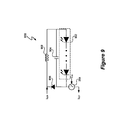
- FIG. 9 depicts a light source 900 , which represents one embodiment of load 210 .
- Light source 900 includes one or more LEDs 902 and exemplary peripheral circuitry including a capacitor 904 connected across the LEDs 902 , and series connected diode 906 and inductor 908 connected in parallel with capacitor 904 and LEDs 902 .
- an electronic system includes a Hall sensor to sense a controlled current, and a controller receives information either directly or indirectly from the Hall sensor corresponding to the controlled current and utilizes the information from the Hall sensor to control conductivity of a switch.
- controlling conductivity of the switch controls a drive current for a load.
- utilizing the Hall sensor to detect the controlled current i CCT is more accurate than using a sense resistor (such as sense resistor 109 ( FIG. 1 )) and dissipates less power than using the sense resistor.
- the controlled current sensed by the Hall sensor 203 is representative of an actual controlled current i CCT but is not the current flowing through the load.
- a current mirror can be used to mirror the controlled current i CCT and the controlled current sensed by the Hall sensor 203 is the mirrored current.
Landscapes
- Physics & Mathematics (AREA)
- General Physics & Mathematics (AREA)
- Condensed Matter Physics & Semiconductors (AREA)
- Measuring Magnetic Variables (AREA)
Abstract
Description
Claims (44)
Priority Applications (1)
| Application Number | Priority Date | Filing Date | Title |
|---|---|---|---|
| US12/495,142 US8963535B1 (en) | 2009-06-30 | 2009-06-30 | Switch controlled current sensing using a hall effect sensor |
Applications Claiming Priority (1)
| Application Number | Priority Date | Filing Date | Title |
|---|---|---|---|
| US12/495,142 US8963535B1 (en) | 2009-06-30 | 2009-06-30 | Switch controlled current sensing using a hall effect sensor |
Publications (1)
| Publication Number | Publication Date |
|---|---|
| US8963535B1 true US8963535B1 (en) | 2015-02-24 |
Family
ID=52472956
Family Applications (1)
| Application Number | Title | Priority Date | Filing Date |
|---|---|---|---|
| US12/495,142 Active 2032-05-31 US8963535B1 (en) | 2009-06-30 | 2009-06-30 | Switch controlled current sensing using a hall effect sensor |
Country Status (1)
| Country | Link |
|---|---|
| US (1) | US8963535B1 (en) |
Cited By (12)
| Publication number | Priority date | Publication date | Assignee | Title |
|---|---|---|---|---|
| US20140103834A1 (en) * | 2011-04-29 | 2014-04-17 | Tridonic Gmbh & Co. Kg | Device for controlling a lighting device |
| US20150305101A1 (en) * | 2011-12-13 | 2015-10-22 | Koninklijke Philips N.V. | Device for controlling a storage device |
| EP3076190A1 (en) * | 2015-04-02 | 2016-10-05 | Rosemount Aerospace Inc. | System and method for minimizing magnetic field effect on an isolated magnetometer |
| US20160299177A1 (en) * | 2013-12-04 | 2016-10-13 | Schneider Electric It Corporation | Improvement of inverter regulation |
| WO2017083725A1 (en) * | 2015-11-11 | 2017-05-18 | Luminara Worldwide, Llc | Systems and methods for reducing energy requirements of an electric light |
| US9894722B2 (en) * | 2013-11-08 | 2018-02-13 | Philips Lighting Holding B.V. | Driver with open output protection |
| US20180234055A1 (en) * | 2017-02-10 | 2018-08-16 | Cirrus Logic International Semiconductor Ltd. | Boosted amplifier with current limiting |
| US20190074145A1 (en) * | 2017-09-01 | 2019-03-07 | Te Connectivity Corporation | Pin configurable smart current sensor |
| US10398004B1 (en) * | 2018-07-06 | 2019-08-27 | Elb Electronics, Inc. | LED fluorescent lamp emulator circuitry |
| US10637369B2 (en) | 2015-10-20 | 2020-04-28 | Schneider Electric It Corporation | Current sensing system for full-bridge pulse-width modulated inverter system |
| US10826452B2 (en) | 2017-02-10 | 2020-11-03 | Cirrus Logic, Inc. | Charge pump with current mode output power throttling |
| US11539282B2 (en) * | 2020-06-16 | 2022-12-27 | Fuji Electric Co., Ltd. | Switching control circuit and power supply circuit |
Citations (263)
| Publication number | Priority date | Publication date | Assignee | Title |
|---|---|---|---|---|
| US3316495A (en) | 1964-07-06 | 1967-04-25 | Cons Systems Corp | Low-level commutator with means for providing common mode rejection |
| US3423689A (en) | 1965-08-19 | 1969-01-21 | Hewlett Packard Co | Direct current amplifier |
| US3586988A (en) | 1967-12-01 | 1971-06-22 | Newport Lab | Direct coupled differential amplifier |
| US3725804A (en) | 1971-11-26 | 1973-04-03 | Avco Corp | Capacitance compensation circuit for differential amplifier |
| US3790878A (en) | 1971-12-22 | 1974-02-05 | Keithley Instruments | Switching regulator having improved control circuiting |
| US3881167A (en) | 1973-07-05 | 1975-04-29 | Pelton Company Inc | Method and apparatus to maintain constant phase between reference and output signals |
| US4075701A (en) | 1975-02-12 | 1978-02-21 | Messerschmitt-Bolkow-Blohm Gesellschaft Mit Beschrankter Haftung | Method and circuit arrangement for adapting the measuring range of a measuring device operating with delta modulation in a navigation system |
| GB2069269A (en) | 1980-02-11 | 1981-08-19 | Tektronix Inc | Supply voltage driver |
| US4334250A (en) | 1978-03-16 | 1982-06-08 | Tektronix, Inc. | MFM data encoder with write precompensation |
| US4409476A (en) | 1980-06-16 | 1983-10-11 | Asea Aktiebolag | Fiber optic temperature-measuring apparatus |
| US4414493A (en) | 1981-10-06 | 1983-11-08 | Thomas Industries Inc. | Light dimmer for solid state ballast |
| US4476706A (en) | 1982-01-18 | 1984-10-16 | Delphian Partners | Remote calibration system |
| US4523128A (en) | 1982-12-10 | 1985-06-11 | Honeywell Inc. | Remote control of dimmable electronic gas discharge lamp ballasts |
| US4677366A (en) | 1986-05-12 | 1987-06-30 | Pioneer Research, Inc. | Unity power factor power supply |
| US4683529A (en) | 1986-11-12 | 1987-07-28 | Zytec Corporation | Switching power supply with automatic power factor correction |
| US4700188A (en) | 1985-01-29 | 1987-10-13 | Micronic Interface Technologies | Electric power measurement system and hall effect based electric power meter for use therein |
| US4737658A (en) | 1985-08-05 | 1988-04-12 | Brown, Boveri & Cie Ag | Centralized control receiver |
| US4797633A (en) | 1987-03-20 | 1989-01-10 | Video Sound, Inc. | Audio amplifier |
| US4937728A (en) | 1989-03-07 | 1990-06-26 | Rca Licensing Corporation | Switch-mode power supply with burst mode standby operation |
| US4940929A (en) | 1989-06-23 | 1990-07-10 | Apollo Computer, Inc. | AC to DC converter with unity power factor |
| US4973919A (en) | 1989-03-23 | 1990-11-27 | Doble Engineering Company | Amplifying with directly coupled, cascaded amplifiers |
| US4979087A (en) | 1988-09-09 | 1990-12-18 | Aviation Limited | Inductive coupler |
| US4980898A (en) | 1989-08-08 | 1990-12-25 | Siemens-Pacesetter, Inc. | Self-oscillating burst mode transmitter with integral number of periods |
| US4992919A (en) | 1989-12-29 | 1991-02-12 | Lee Chu Quon | Parallel resonant converter with zero voltage switching |
| US4994952A (en) | 1988-02-10 | 1991-02-19 | Electronics Research Group, Inc. | Low-noise switching power supply having variable reluctance transformer |
| US5001620A (en) | 1988-07-25 | 1991-03-19 | Astec International Limited | Power factor improvement |
| US5055746A (en) | 1990-08-13 | 1991-10-08 | Electronic Ballast Technology, Incorporated | Remote control of fluorescent lamp ballast using power flow interruption coding with means to maintain filament voltage substantially constant as the lamp voltage decreases |
| US5109185A (en) | 1989-09-29 | 1992-04-28 | Ball Newton E | Phase-controlled reversible power converter presenting a controllable counter emf to a source of an impressed voltage |
| US5121079A (en) | 1991-02-12 | 1992-06-09 | Dargatz Marvin R | Driven-common electronic amplifier |
| US5206540A (en) | 1991-05-09 | 1993-04-27 | Unitrode Corporation | Transformer isolated drive circuit |
| US5264780A (en) | 1992-08-10 | 1993-11-23 | International Business Machines Corporation | On time control and gain circuit |
| US5278490A (en) | 1990-09-04 | 1994-01-11 | California Institute Of Technology | One-cycle controlled switching circuit |
| EP0585789A1 (en) | 1992-09-01 | 1994-03-09 | Power Integrations, Inc. | Three-terminal switched mode power supply integrated circuit |
| US5323157A (en) | 1993-01-15 | 1994-06-21 | Motorola, Inc. | Sigma-delta digital-to-analog converter with reduced noise |
| US5359180A (en) | 1992-10-02 | 1994-10-25 | General Electric Company | Power supply system for arcjet thrusters |
| EP0632679A1 (en) | 1993-06-22 | 1995-01-04 | Siemens Aktiengesellschaft | Method and circuit for control of room lighting |
| US5383109A (en) | 1993-12-10 | 1995-01-17 | University Of Colorado | High power factor boost rectifier apparatus |
| US5424932A (en) | 1993-01-05 | 1995-06-13 | Yokogawa Electric Corporation | Multi-output switching power supply having an improved secondary output circuit |
| US5477481A (en) | 1991-02-15 | 1995-12-19 | Crystal Semiconductor Corporation | Switched-capacitor integrator with chopper stabilization performed at the sampling rate |
| US5479333A (en) | 1994-04-25 | 1995-12-26 | Chrysler Corporation | Power supply start up booster circuit |
| US5481178A (en) | 1993-03-23 | 1996-01-02 | Linear Technology Corporation | Control circuit and method for maintaining high efficiency over broad current ranges in a switching regulator circuit |
| US5565761A (en) | 1994-09-02 | 1996-10-15 | Micro Linear Corp | Synchronous switching cascade connected offline PFC-PWM combination power converter controller |
| US5589759A (en) | 1992-07-30 | 1996-12-31 | Sgs-Thomson Microelectronics S.R.L. | Circuit for detecting voltage variations in relation to a set value, for devices comprising error amplifiers |
| US5638265A (en) | 1993-08-24 | 1997-06-10 | Gabor; George | Low line harmonic AC to DC power supply |
| WO1997025836A1 (en) | 1996-01-04 | 1997-07-17 | Honeywell Inc. | Method of semiautomatic ambient light sensor calibration in an automatic control system |
| US5691890A (en) | 1995-12-01 | 1997-11-25 | International Business Machines Corporation | Power supply with power factor correction circuit |
| US5747977A (en) | 1995-03-30 | 1998-05-05 | Micro Linear Corporation | Switching regulator having low power mode responsive to load power consumption |
| US5757635A (en) | 1995-12-28 | 1998-05-26 | Samsung Electronics Co., Ltd. | Power factor correction circuit and circuit therefor having sense-FET and boost converter control circuit |
| US5764039A (en) | 1995-11-15 | 1998-06-09 | Samsung Electronics Co., Ltd. | Power factor correction circuit having indirect input voltage sensing |
| US5768111A (en) | 1995-02-27 | 1998-06-16 | Nec Corporation | Converter comprising a piezoelectric transformer and a switching stage of a resonant frequency different from that of the transformer |
| US5781040A (en) | 1996-10-31 | 1998-07-14 | Hewlett-Packard Company | Transformer isolated driver for power transistor using frequency switching as the control signal |
| US5783909A (en) | 1997-01-10 | 1998-07-21 | Relume Corporation | Maintaining LED luminous intensity |
| US5798635A (en) | 1996-06-20 | 1998-08-25 | Micro Linear Corporation | One pin error amplifier and switched soft-start for an eight pin PFC-PWM combination integrated circuit converter controller |
| DE19713814A1 (en) | 1997-04-03 | 1998-10-15 | Siemens Ag | Switching power supply |
| EP0910168A1 (en) | 1997-10-16 | 1999-04-21 | Hewlett-Packard Company | Delta-sigma pulse width modulator |
| US5900683A (en) | 1997-12-23 | 1999-05-04 | Ford Global Technologies, Inc. | Isolated gate driver for power switching device and method for carrying out same |
| US5912812A (en) | 1996-12-19 | 1999-06-15 | Lucent Technologies Inc. | Boost power converter for powering a load from an AC source |
| US5929400A (en) | 1997-12-22 | 1999-07-27 | Otis Elevator Company | Self commissioning controller for field-oriented elevator motor/drive system |
| US5946202A (en) | 1997-01-24 | 1999-08-31 | Baker Hughes Incorporated | Boost mode power conversion |
| US5946206A (en) | 1997-02-17 | 1999-08-31 | Tdk Corporation | Plural parallel resonant switching power supplies |
| US5952849A (en) | 1997-02-21 | 1999-09-14 | Analog Devices, Inc. | Logic isolator with high transient immunity |
| US5960207A (en) | 1997-01-21 | 1999-09-28 | Dell Usa, L.P. | System and method for reducing power losses by gating an active power factor conversion process |
| US5963086A (en) | 1997-08-08 | 1999-10-05 | Velodyne Acoustics, Inc. | Class D amplifier with switching control |
| US5962989A (en) | 1995-01-17 | 1999-10-05 | Negawatt Technologies Inc. | Energy management control system |
| US5966297A (en) | 1997-08-28 | 1999-10-12 | Iwatsu Electric Co., Ltd. | Large bandwidth analog isolation circuit |
| EP0838791A3 (en) | 1996-10-25 | 1999-11-17 | Hubbell Incorporated | Multifunction sensor and network sensor system |
| US6016038A (en) | 1997-08-26 | 2000-01-18 | Color Kinetics, Inc. | Multicolored LED lighting method and apparatus |
| US6037763A (en) * | 1995-03-16 | 2000-03-14 | Horstmann Timers & Controls Limited | Electricity measurement apparatus using hall effect sensor having rectified bias current |
| US6043633A (en) | 1998-06-05 | 2000-03-28 | Systel Development & Industries | Power factor correction method and apparatus |
| US6072969A (en) | 1996-03-05 | 2000-06-06 | Canon Kabushiki Kaisha | Developing cartridge |
| US6084450A (en) | 1997-01-14 | 2000-07-04 | The Regents Of The University Of California | PWM controller with one cycle response |
| US6083276A (en) | 1998-06-11 | 2000-07-04 | Corel, Inc. | Creating and configuring component-based applications using a text-based descriptive attribute grammar |
| US6091233A (en) | 1999-01-14 | 2000-07-18 | Micro Linear Corporation | Interleaved zero current switching in a power factor correction boost converter |
| US6125046A (en) | 1998-11-10 | 2000-09-26 | Fairfield Korea Semiconductor Ltd. | Switching power supply having a high efficiency starting circuit |
| US6181114B1 (en) | 1999-10-26 | 2001-01-30 | International Business Machines Corporation | Boost circuit which includes an additional winding for providing an auxiliary output voltage |
| WO2001015316A1 (en) | 1999-08-23 | 2001-03-01 | Intel Corporation | Method and apparatus for matching common mode output voltage at a switched-capacitor to continuous-time interface |
| US6211627B1 (en) | 1997-07-29 | 2001-04-03 | Michael Callahan | Lighting systems |
| US6211626B1 (en) | 1997-08-26 | 2001-04-03 | Color Kinetics, Incorporated | Illumination components |
| US6229292B1 (en) | 1999-02-12 | 2001-05-08 | Analog Devices, Inc. | Voltage regulator compensation circuit and method |
| US6229271B1 (en) | 2000-02-24 | 2001-05-08 | Osram Sylvania Inc. | Low distortion line dimmer and dimming ballast |
| US6246183B1 (en) | 2000-02-28 | 2001-06-12 | Litton Systems, Inc. | Dimmable electrodeless light source |
| US6259614B1 (en) | 1999-07-12 | 2001-07-10 | International Rectifier Corporation | Power factor correction control circuit |
| US6300723B1 (en) | 1998-07-29 | 2001-10-09 | Philips Electronics North America Corporation | Apparatus for power factor control |
| US6304473B1 (en) | 2000-06-02 | 2001-10-16 | Iwatt | Operating a power converter at optimal efficiency |
| US6343026B1 (en) | 2000-11-09 | 2002-01-29 | Artesyn Technologies, Inc. | Current limit circuit for interleaved converters |
| US6344811B1 (en) | 1999-03-16 | 2002-02-05 | Audio Logic, Inc. | Power supply compensation for noise shaped, digital amplifiers |
| WO2002015386A2 (en) | 2000-08-14 | 2002-02-21 | K.S. Waves Ltd. | High-efficiency audio power amplifier |
| US6369525B1 (en) | 2000-11-21 | 2002-04-09 | Philips Electronics North America | White light-emitting-diode lamp driver based on multiple output converter with output current mode control |
| US6385063B1 (en) | 1998-06-23 | 2002-05-07 | Siemens Aktiengesellschaft | Hybrid filter for an alternating current network |
| US6392400B1 (en) * | 1998-10-08 | 2002-05-21 | Schlumberger Resource Management Services | High linearity, low offset interface for Hall effect devices |
| US20020065583A1 (en) | 2000-11-30 | 2002-05-30 | Matsushita Electric Works, Ltd. | Setting apparatus and setting method each for setting setting information in electric power line carrier communication terminal apparatus |
| EP1213823A2 (en) | 2000-12-04 | 2002-06-12 | Sanken Electric Co., Ltd. | DC-to-DC converter |
| US6407691B1 (en) | 2000-10-18 | 2002-06-18 | Cirrus Logic, Inc. | Providing power, clock, and control signals as a single combined signal across an isolation barrier in an ADC |
| US6407514B1 (en) | 2001-03-29 | 2002-06-18 | General Electric Company | Non-synchronous control of self-oscillating resonant converters |
| US6407515B1 (en) | 1999-11-12 | 2002-06-18 | Lighting Control, Inc. | Power regulator employing a sinusoidal reference |
| US6441558B1 (en) | 2000-12-07 | 2002-08-27 | Koninklijke Philips Electronics N.V. | White LED luminary light control system |
| US6445600B2 (en) * | 1998-07-13 | 2002-09-03 | Ben-Gurion University Of The Negev Research & Development Authority | Modular structure of an apparatus for regulating the harmonics of current drawn from power lines by an electronic load |
| US6452521B1 (en) | 2001-03-14 | 2002-09-17 | Rosemount Inc. | Mapping a delta-sigma converter range to a sensor range |
| US20020145041A1 (en) | 2001-03-16 | 2002-10-10 | Koninklijke Philips Electronics N.V. | RGB LED based light driver using microprocessor controlled AC distributed power system |
| US20020150151A1 (en) | 1997-04-22 | 2002-10-17 | Silicon Laboratories Inc. | Digital isolation system with hybrid circuit in ADC calibration loop |
| US6469484B2 (en) | 2000-12-13 | 2002-10-22 | Semiconductor Components Industries Llc | Power supply circuit and method thereof to detect demagnitization of the power supply |
| US20020166073A1 (en) | 2001-05-02 | 2002-11-07 | Nguyen James Hung | Apparatus and method for adaptively controlling power supplied to a hot-pluggable subsystem |
| WO2002091805A2 (en) | 2001-05-10 | 2002-11-14 | Color Kinetics Incorporated | Systems and methods for synchronizing lighting effects |
| US20020186010A1 (en) * | 2000-09-26 | 2002-12-12 | Wolfgang Kliemannel | Hall-sensor component |
| US6495964B1 (en) | 1998-12-18 | 2002-12-17 | Koninklijke Philips Electronics N.V. | LED luminaire with electrically adjusted color balance using photodetector |
| US6509913B2 (en) | 1998-04-30 | 2003-01-21 | Openwave Systems Inc. | Configurable man-machine interface |
| US6531854B2 (en) | 2001-03-30 | 2003-03-11 | Champion Microelectronic Corp. | Power factor correction circuit arrangement |
| US20030095013A1 (en) | 2000-05-10 | 2003-05-22 | Melanson John L. | Modulation of a digital input signal using a digital signal modulator and signal splitting |
| US6583550B2 (en) | 2000-10-24 | 2003-06-24 | Toyoda Gosei Co., Ltd. | Fluorescent tube with light emitting diodes |
| WO2002027944A3 (en) | 2000-09-29 | 2003-08-14 | Teradyne Inc | Digital to analog converter employing sigma-delta loop and feedback dac model |
| US20030174520A1 (en) | 2000-10-24 | 2003-09-18 | Igor Bimbaud | Self-oscillating control circuit voltage converter |
| US6628106B1 (en) | 2001-07-30 | 2003-09-30 | University Of Central Florida | Control method and circuit to provide voltage and current regulation for multiphase DC/DC converters |
| US6636003B2 (en) | 2000-09-06 | 2003-10-21 | Spectrum Kinetics | Apparatus and method for adjusting the color temperature of white semiconduct or light emitters |
| US6646848B2 (en) | 2001-01-31 | 2003-11-11 | Matsushita Electric Industrial Co., Ltd. | Switching power supply apparatus |
| US6657417B1 (en) | 2002-05-31 | 2003-12-02 | Champion Microelectronic Corp. | Power factor correction with carrier control and input voltage sensing |
| US20030223255A1 (en) | 2002-05-31 | 2003-12-04 | Green Power Technologies Ltd. | Method and apparatus for active power factor correction with minimum input current distortion |
| US20040004465A1 (en) | 2002-07-08 | 2004-01-08 | Cogency Semiconductor Inc. | Dual-output direct current voltage converter |
| US6688753B2 (en) | 2001-02-02 | 2004-02-10 | Koninklijke Philips Electronics N.V. | Integrated light source |
| EP1164819B1 (en) | 2000-06-15 | 2004-02-11 | City University of Hong Kong | Dimmable electronic ballast |
| US20040046683A1 (en) | 2001-03-08 | 2004-03-11 | Shindengen Electric Manufacturing Co., Ltd. | DC stabilized power supply |
| US6713974B2 (en) | 2002-01-10 | 2004-03-30 | Lightech Electronic Industries Ltd. | Lamp transformer for use with an electronic dimmer and method for use thereof for reducing acoustic noise |
| US6724174B1 (en) | 2002-09-12 | 2004-04-20 | Linear Technology Corp. | Adjustable minimum peak inductor current level for burst mode in current-mode DC-DC regulators |
| US6727832B1 (en) | 2002-11-27 | 2004-04-27 | Cirrus Logic, Inc. | Data converters with digitally filtered pulse width modulation output stages and methods and systems using the same |
| US20040085117A1 (en) | 2000-12-06 | 2004-05-06 | Joachim Melbert | Method and device for switching on and off power semiconductors, especially for the torque-variable operation of an asynchronous machine, for operating an ignition system for spark ignition engines, and switched-mode power supply |
| US20040085030A1 (en) | 2002-10-30 | 2004-05-06 | Benoit Laflamme | Multicolor lamp system |
| US6737845B2 (en) | 2001-06-21 | 2004-05-18 | Champion Microelectronic Corp. | Current inrush limiting and bleed resistor current inhibiting in a switching power converter |
| US6741123B1 (en) | 2002-12-26 | 2004-05-25 | Cirrus Logic, Inc. | Delta-sigma amplifiers with output stage supply voltage variation compensation and methods and digital amplifier systems using the same |
| US6753661B2 (en) | 2002-06-17 | 2004-06-22 | Koninklijke Philips Electronics N.V. | LED-based white-light backlighting for electronic displays |
| US6768655B1 (en) | 2003-02-03 | 2004-07-27 | System General Corp. | Discontinuous mode PFC controller having a power saving modulator and operation method thereof |
| US6781351B2 (en) | 2002-08-17 | 2004-08-24 | Supertex Inc. | AC/DC cascaded power converters having high DC conversion ratio and improved AC line harmonics |
| US20040169477A1 (en) | 2003-02-28 | 2004-09-02 | Naoki Yanai | Dimming-control lighting apparatus for incandescent electric lamp |
| US6788011B2 (en) | 1997-08-26 | 2004-09-07 | Color Kinetics, Incorporated | Multicolored LED lighting method and apparatus |
| US20040227571A1 (en) | 2003-05-12 | 2004-11-18 | Yasuji Kuribayashi | Power amplifier circuit |
| US20040228116A1 (en) | 2003-05-13 | 2004-11-18 | Carroll Miller | Electroluminescent illumination for a magnetic compass |
| US20040232971A1 (en) | 2003-03-06 | 2004-11-25 | Denso Corporation | Electrically insulated switching element drive circuit |
| US20040239262A1 (en) | 2002-05-28 | 2004-12-02 | Shigeru Ido | Electronic ballast for a discharge lamp |
| US6839247B1 (en) | 2003-07-10 | 2005-01-04 | System General Corp. | PFC-PWM controller having a power saving means |
| US6860628B2 (en) | 2002-07-17 | 2005-03-01 | Jonas J. Robertson | LED replacement for fluorescent lighting |
| US20050057237A1 (en) | 2002-01-11 | 2005-03-17 | Robert Clavel | Power factor controller |
| US6870325B2 (en) | 2002-02-22 | 2005-03-22 | Oxley Developments Company Limited | Led drive circuit and method |
| US6873065B2 (en) | 1997-10-23 | 2005-03-29 | Analog Devices, Inc. | Non-optical signal isolator |
| US6882552B2 (en) | 2000-06-02 | 2005-04-19 | Iwatt, Inc. | Power converter driven by power pulse and sense pulse |
| US6888322B2 (en) | 1997-08-26 | 2005-05-03 | Color Kinetics Incorporated | Systems and methods for color changing device and enclosure |
| EP1528785A1 (en) | 2003-10-14 | 2005-05-04 | Archimede Elettronica S.r.l. | Device and method for controlling the color of a light source |
| US6894471B2 (en) | 2002-05-31 | 2005-05-17 | St Microelectronics S.R.L. | Method of regulating the supply voltage of a load and related voltage regulator |
| US20050156770A1 (en) | 2004-01-16 | 2005-07-21 | Melanson John L. | Jointly nonlinear delta sigma modulators |
| US20050168492A1 (en) | 2002-05-28 | 2005-08-04 | Koninklijke Philips Electronics N.V. | Motion blur decrease in varying duty cycle |
| US6933706B2 (en) | 2003-09-15 | 2005-08-23 | Semiconductor Components Industries, Llc | Method and circuit for optimizing power efficiency in a DC-DC converter |
| US20050184895A1 (en) | 2004-02-25 | 2005-08-25 | Nellcor Puritan Bennett Inc. | Multi-bit ADC with sigma-delta modulation |
| US6940733B2 (en) | 2002-08-22 | 2005-09-06 | Supertex, Inc. | Optimal control of wide conversion ratio switching converters |
| US20050197952A1 (en) | 2003-08-15 | 2005-09-08 | Providus Software Solutions, Inc. | Risk mitigation management |
| US6944034B1 (en) | 2003-06-30 | 2005-09-13 | Iwatt Inc. | System and method for input current shaping in a power converter |
| US20050207190A1 (en) | 2004-03-22 | 2005-09-22 | Gritter David J | Power system having a phase locked loop with a notch filter |
| US20050218838A1 (en) | 2004-03-15 | 2005-10-06 | Color Kinetics Incorporated | LED-based lighting network power control methods and apparatus |
| US20050222881A1 (en) | 2004-04-05 | 2005-10-06 | Garry Booker | Management work system and method |
| US6956750B1 (en) | 2003-05-16 | 2005-10-18 | Iwatt Inc. | Power converter controller having event generator for detection of events and generation of digital error |
| US6958920B2 (en) | 2003-10-02 | 2005-10-25 | Supertex, Inc. | Switching power converter and method of controlling output voltage thereof using predictive sensing of magnetic flux |
| US20050253533A1 (en) | 2002-05-09 | 2005-11-17 | Color Kinetics Incorporated | Dimmable LED-based MR16 lighting apparatus methods |
| US6967448B2 (en) | 1997-08-26 | 2005-11-22 | Color Kinetics, Incorporated | Methods and apparatus for controlling illumination |
| US6970503B1 (en) | 2000-04-21 | 2005-11-29 | National Semiconductor Corporation | Apparatus and method for converting analog signal to pulse-width-modulated signal |
| US20050270813A1 (en) | 2004-06-04 | 2005-12-08 | Wanfeng Zhang | Parallel current mode control |
| US6975079B2 (en) | 1997-08-26 | 2005-12-13 | Color Kinetics Incorporated | Systems and methods for controlling illumination sources |
| US6975523B2 (en) | 2002-10-16 | 2005-12-13 | Samsung Electronics Co., Ltd. | Power supply capable of protecting electric device circuit |
| US20050275354A1 (en) | 2004-06-10 | 2005-12-15 | Hausman Donald F Jr | Apparatus and methods for regulating delivery of electrical energy |
| US20050275386A1 (en) | 2002-06-23 | 2005-12-15 | Powerlynx A/S | Power converter |
| US6980446B2 (en) | 2002-02-08 | 2005-12-27 | Sanken Electric Co., Ltd. | Circuit for starting power source apparatus |
| US20060002110A1 (en) | 2004-03-15 | 2006-01-05 | Color Kinetics Incorporated | Methods and systems for providing lighting systems |
| US20060022916A1 (en) | 2004-06-14 | 2006-02-02 | Natale Aiello | LED driving device with variable light intensity |
| US20060023002A1 (en) | 2004-08-02 | 2006-02-02 | Oki Electric Industry Co., Ltd. | Color balancing circuit for a display panel |
| EP1014563B1 (en) | 1998-12-14 | 2006-03-01 | Alcatel | Amplifier arrangement with voltage gain and reduced power consumption |
| US7034611B2 (en) | 2004-02-09 | 2006-04-25 | Texas Instruments Inc. | Multistage common mode feedback for improved linearity line drivers |
| US20060116898A1 (en) | 2003-11-18 | 2006-06-01 | Peterson Gary E | Interactive risk management system and method with reputation risk management |
| US20060125420A1 (en) | 2004-12-06 | 2006-06-15 | Michael Boone | Candle emulation device |
| US7064498B2 (en) | 1997-08-26 | 2006-06-20 | Color Kinetics Incorporated | Light-emitting diode based products |
| US7064531B1 (en) | 2005-03-31 | 2006-06-20 | Micrel, Inc. | PWM buck regulator with LDO standby mode |
| WO2006067521A1 (en) | 2004-12-20 | 2006-06-29 | Outside In (Cambridge) Limited | Lightning apparatus and method |
| US7072191B2 (en) | 2002-04-26 | 2006-07-04 | Fdk Corporation | Switching power source circuit for independent per cycle control of ON/OFF time ratio |
| US7075329B2 (en) | 2003-04-30 | 2006-07-11 | Analog Devices, Inc. | Signal isolators using micro-transformers |
| US7078963B1 (en) | 2003-03-21 | 2006-07-18 | D2Audio Corporation | Integrated PULSHI mode with shutdown |
| US7088059B2 (en) | 2004-07-21 | 2006-08-08 | Boca Flasher | Modulated control circuit and method for current-limited dimming and color mixing of display and illumination systems |
| US20060184414A1 (en) | 2005-02-11 | 2006-08-17 | George Pappas | Business management tool |
| US7099163B1 (en) | 2005-11-14 | 2006-08-29 | Bcd Semiconductor Manufacturing Limited | PWM controller with constant output power limit for a power supply |
| US7102902B1 (en) | 2005-02-17 | 2006-09-05 | Ledtronics, Inc. | Dimmer circuit for LED |
| US7106603B1 (en) | 2005-05-23 | 2006-09-12 | Li Shin International Enterprise Corporation | Switch-mode self-coupling auxiliary power device |
| US7109791B1 (en) | 2004-07-09 | 2006-09-19 | Rf Micro Devices, Inc. | Tailored collector voltage to minimize variation in AM to PM distortion in a power amplifier |
| US20060214603A1 (en) | 2005-03-22 | 2006-09-28 | In-Hwan Oh | Single-stage digital power converter for driving LEDs |
| US20060226795A1 (en) | 2005-04-08 | 2006-10-12 | S.C. Johnson & Son, Inc. | Lighting device having a circuit including a plurality of light emitting diodes, and methods of controlling and calibrating lighting devices |
| US7126288B2 (en) | 2003-05-05 | 2006-10-24 | International Rectifier Corporation | Digital electronic ballast control apparatus and method |
| US20060238136A1 (en) | 2003-07-02 | 2006-10-26 | Johnson Iii H F | Lamp and bulb for illumination and ambiance lighting |
| US20060261754A1 (en) * | 2005-05-18 | 2006-11-23 | Samsung Electro-Mechanics Co., Ltd. | LED driving circuit having dimming circuit |
| US7145295B1 (en) | 2005-07-24 | 2006-12-05 | Aimtron Technology Corp. | Dimming control circuit for light-emitting diodes |
| US20060285365A1 (en) | 2005-06-16 | 2006-12-21 | Active Semiconductors International Inc. | Primary side constant output current controller |
| WO2006135584A1 (en) | 2005-06-10 | 2006-12-21 | Rf Micro Devices, Inc. | Doherty amplifier configuration for a collector controlled power amplifier |
| US7158633B1 (en) | 1999-11-16 | 2007-01-02 | Silicon Laboratories, Inc. | Method and apparatus for monitoring subscriber loop interface circuitry power dissipation |
| US20070024213A1 (en) | 2005-07-28 | 2007-02-01 | Synditec, Inc. | Pulsed current averaging controller with amplitude modulation and time division multiplexing for arrays of independent pluralities of light emitting diodes |
| US20070029946A1 (en) | 2005-08-03 | 2007-02-08 | Yu Chung-Che | APPARATUS OF LIGHT SOURCE AND ADJUSTABLE CONTROL CIRCUIT FOR LEDs |
| US7180250B1 (en) | 2005-01-25 | 2007-02-20 | Henry Michael Gannon | Triac-based, low voltage AC dimmer |
| US20070040512A1 (en) | 2005-08-17 | 2007-02-22 | Tir Systems Ltd. | Digitally controlled luminaire system |
| US7183957B1 (en) | 2005-12-30 | 2007-02-27 | Cirrus Logic, Inc. | Signal processing system with analog-to-digital converter using delta-sigma modulation having an internal stabilizer loop |
| EP1460775B8 (en) | 2003-03-18 | 2007-02-28 | POWER ONE ITALY S.p.A. | Lighting control with power line modem |
| US20070055564A1 (en) | 2003-06-20 | 2007-03-08 | Fourman Clive M | System for facilitating management and organisational development processes |
| US20070053182A1 (en) | 2005-09-07 | 2007-03-08 | Jonas Robertson | Combination fluorescent and LED lighting system |
| US20070096717A1 (en) * | 2005-10-31 | 2007-05-03 | Denso Corporation | Current sensor and method of manufacturing the same |
| US20070103949A1 (en) | 2004-08-27 | 2007-05-10 | Sanken Electric Co., Ltd. | Power factor improving circuit |
| WO2006013557A3 (en) | 2004-08-02 | 2007-05-18 | Green Power Technologies Ltd | Method and control circuitry for improved-performance switch-mode converters |
| US7221130B2 (en) | 2005-01-05 | 2007-05-22 | Fyrestorm, Inc. | Switching power converter employing pulse frequency modulation control |
| US20070124615A1 (en) | 2005-11-29 | 2007-05-31 | Potentia Semiconductor Corporation | Standby arrangement for power supplies |
| US20070126656A1 (en) | 2005-12-07 | 2007-06-07 | Industrial Technology Research Institute | Illumination brightness and color control system and method therefor |
| WO2007026170A3 (en) | 2005-09-03 | 2007-06-14 | Light Ltd E | Improvements to lighting systems |
| US7233135B2 (en) | 2003-09-29 | 2007-06-19 | Murata Manufacturing Co., Ltd. | Ripple converter |
| US7246919B2 (en) | 2004-03-03 | 2007-07-24 | S.C. Johnson & Son, Inc. | LED light bulb with active ingredient emission |
| US20070182699A1 (en) | 2006-02-09 | 2007-08-09 | Samsung Electro-Mechanics Co., Ltd. | Field sequential color mode liquid crystal display |
| US7255457B2 (en) | 1999-11-18 | 2007-08-14 | Color Kinetics Incorporated | Methods and apparatus for generating and modulating illumination conditions |
| US7266001B1 (en) | 2004-03-19 | 2007-09-04 | Marvell International Ltd. | Method and apparatus for controlling power factor correction |
| US7265531B2 (en) * | 2002-09-20 | 2007-09-04 | Allegro Microsystems, Inc. | Integrated current sensor |
| US7276861B1 (en) | 2004-09-21 | 2007-10-02 | Exclara, Inc. | System and method for driving LED |
| US7288902B1 (en) | 2007-03-12 | 2007-10-30 | Cirrus Logic, Inc. | Color variations in a dimmable lighting device with stable color temperature light sources |
| US7292013B1 (en) | 2004-09-24 | 2007-11-06 | Marvell International Ltd. | Circuits, systems, methods, and software for power factor correction and/or control |
| US7310244B2 (en) | 2006-01-25 | 2007-12-18 | System General Corp. | Primary side controlled switching regulator |
| US20080027841A1 (en) | 2002-01-16 | 2008-01-31 | Jeff Scott Eder | System for integrating enterprise performance management |
| US20080043504A1 (en) | 2006-08-16 | 2008-02-21 | On-Bright Electronics (Shanghai) Co., Ltd. | System and method for providing control for switch-mode power supply |
| US20080054815A1 (en) | 2006-09-01 | 2008-03-06 | Broadcom Corporation | Single inductor serial-parallel LED driver |
| US7345458B2 (en) | 2003-07-07 | 2008-03-18 | Nippon Telegraph And Telephone Corporation | Booster that utilizes energy output from a power supply unit |
| US20080094055A1 (en) * | 2006-10-19 | 2008-04-24 | Gerardo Monreal | Chopped hall effect sensor |
| US20080116818A1 (en) | 2006-11-21 | 2008-05-22 | Exclara Inc. | Time division modulation with average current regulation for independent control of arrays of light emitting diodes |
| US20080130336A1 (en) | 2005-07-01 | 2008-06-05 | Yasutaka Taguchi | Power Supply Device |
| US20080130322A1 (en) | 2006-12-01 | 2008-06-05 | Artusi Daniel A | Power system with power converters having an adaptive controller |
| WO2008072160A1 (en) | 2006-12-13 | 2008-06-19 | Koninklijke Philips Electronics N.V. | Method for light emitting diode control and corresponding light sensor array, backlight and liquid crystal display |
| US20080150433A1 (en) | 2006-12-26 | 2008-06-26 | Kabushiki Kaisha Toshiba | Backlight control unit and backlight control method |
| US20080154679A1 (en) | 2006-11-03 | 2008-06-26 | Wade Claude E | Method and apparatus for a processing risk assessment and operational oversight framework |
| US7394210B2 (en) | 2004-09-29 | 2008-07-01 | Tir Technology Lp | System and method for controlling luminaires |
| US20080175029A1 (en) | 2007-01-18 | 2008-07-24 | Sang-Hwa Jung | Burst mode operation in a DC-DC converter |
| US20080174372A1 (en) | 2007-01-19 | 2008-07-24 | Tucker John C | Multi-stage amplifier with multiple sets of fixed and variable voltage rails |
| US20080174291A1 (en) | 2002-04-29 | 2008-07-24 | Emerson Energy Systems Ab | Power Supply System and Apparatus |
| US20080192509A1 (en) | 2007-02-13 | 2008-08-14 | Dhuyvetter Timothy A | Dc-dc converter with isolation |
| US7414389B2 (en) * | 2006-06-14 | 2008-08-19 | Intel Corporation | Low-power battery pack with hall-effect sensor |
| US20080232141A1 (en) | 2006-12-01 | 2008-09-25 | Artusi Daniel A | Power System with Power Converters Having an Adaptive Controller |
| US20080239764A1 (en) | 2007-03-30 | 2008-10-02 | Cambridge Semiconductor Limited | Forward power converter controllers |
| US20080259655A1 (en) | 2007-04-19 | 2008-10-23 | Da-Chun Wei | Switching-mode power converter and pulse-width-modulation control circuit with primary-side feedback control |
| US20080278891A1 (en) * | 2006-05-11 | 2008-11-13 | Micronas Gmbh | Monolithic sensor arrangement and method for controlling a monolithic sensor arrangement |
| US20080278132A1 (en) | 2007-05-07 | 2008-11-13 | Kesterson John W | Digital Compensation For Cable Drop In A Primary Side Control Power Supply Controller |
| WO2008152838A1 (en) | 2007-06-14 | 2008-12-18 | Sanken Electric Co., Ltd. | Ac-dc converter |
| US20090070188A1 (en) | 2007-09-07 | 2009-03-12 | Certus Limited (Uk) | Portfolio and project risk assessment |
| US7511437B2 (en) | 2006-02-10 | 2009-03-31 | Philips Solid-State Lighting Solutions, Inc. | Methods and apparatus for high power factor controlled power delivery using a single switching stage per load |
| US7538499B2 (en) | 2005-03-03 | 2009-05-26 | Tir Technology Lp | Method and apparatus for controlling thermal stress in lighting devices |
| US7545130B2 (en) | 2005-11-11 | 2009-06-09 | L&L Engineering, Llc | Non-linear controller for switching power supply |
| US20090147544A1 (en) | 2007-12-11 | 2009-06-11 | Melanson John L | Modulated transformer-coupled gate control signaling method and apparatus |
| US7554473B2 (en) | 2007-05-02 | 2009-06-30 | Cirrus Logic, Inc. | Control system using a nonlinear delta-sigma modulator with nonlinear process modeling |
| US20090174479A1 (en) | 2008-01-04 | 2009-07-09 | Texas Instruments Incorporated | High-voltage differential amplifier and method using low voltage amplifier and dynamic voltage selection |
| US7569996B2 (en) | 2004-03-19 | 2009-08-04 | Fred H Holmes | Omni voltage direct current power supply |
| US7583136B2 (en) | 2000-03-28 | 2009-09-01 | International Rectifier Corporation | Active filter for reduction of common mode current |
| US20090218960A1 (en) | 2007-03-13 | 2009-09-03 | Renaissance Lighting, Inc. | Step-wise intensity control of a solid state lighting system |
| US7656103B2 (en) | 2006-01-20 | 2010-02-02 | Exclara, Inc. | Impedance matching circuit for current regulation of solid state lighting |
| US20100072956A1 (en) * | 2008-09-24 | 2010-03-25 | Fiebrich Greg R | Low Power and Accurate Adapter-Current Detection Scheme for Dynamic Load Balancing |
| US20100141317A1 (en) | 2006-10-11 | 2010-06-10 | Mitsubishi Electric Corporation | Spread-period clock generator |
| US7746671B2 (en) | 2005-05-23 | 2010-06-29 | Infineon Technologies Ag | Control circuit for a switch unit of a clocked power supply circuit, and resonance converter |
| US7750738B2 (en) | 2008-11-20 | 2010-07-06 | Infineon Technologies Ag | Process, voltage and temperature control for high-speed, low-power fixed and variable gain amplifiers based on MOSFET resistors |
| US7756896B1 (en) | 2002-03-11 | 2010-07-13 | Jp Morgan Chase Bank | System and method for multi-dimensional risk analysis |
| US7777563B2 (en) | 2008-12-18 | 2010-08-17 | Freescale Semiconductor, Inc. | Spread spectrum pulse width modulation method and apparatus |
| US7804256B2 (en) | 2007-03-12 | 2010-09-28 | Cirrus Logic, Inc. | Power control system for current regulated light sources |
| US7804480B2 (en) | 2005-12-27 | 2010-09-28 | Lg Display Co., Ltd. | Hybrid backlight driving apparatus for liquid crystal display |
| US7923973B2 (en) * | 2008-09-15 | 2011-04-12 | Power Integrations, Inc. | Method and apparatus to reduce line current harmonics from a power supply |
| US8040114B2 (en) * | 2008-11-07 | 2011-10-18 | Power Integrations, Inc. | Method and apparatus to increase efficiency in a power factor correction circuit |
-
2009
- 2009-06-30 US US12/495,142 patent/US8963535B1/en active Active
Patent Citations (287)
| Publication number | Priority date | Publication date | Assignee | Title |
|---|---|---|---|---|
| US3316495A (en) | 1964-07-06 | 1967-04-25 | Cons Systems Corp | Low-level commutator with means for providing common mode rejection |
| US3423689A (en) | 1965-08-19 | 1969-01-21 | Hewlett Packard Co | Direct current amplifier |
| US3586988A (en) | 1967-12-01 | 1971-06-22 | Newport Lab | Direct coupled differential amplifier |
| US3725804A (en) | 1971-11-26 | 1973-04-03 | Avco Corp | Capacitance compensation circuit for differential amplifier |
| US3790878A (en) | 1971-12-22 | 1974-02-05 | Keithley Instruments | Switching regulator having improved control circuiting |
| US3881167A (en) | 1973-07-05 | 1975-04-29 | Pelton Company Inc | Method and apparatus to maintain constant phase between reference and output signals |
| US4075701A (en) | 1975-02-12 | 1978-02-21 | Messerschmitt-Bolkow-Blohm Gesellschaft Mit Beschrankter Haftung | Method and circuit arrangement for adapting the measuring range of a measuring device operating with delta modulation in a navigation system |
| US4334250A (en) | 1978-03-16 | 1982-06-08 | Tektronix, Inc. | MFM data encoder with write precompensation |
| GB2069269A (en) | 1980-02-11 | 1981-08-19 | Tektronix Inc | Supply voltage driver |
| US4409476A (en) | 1980-06-16 | 1983-10-11 | Asea Aktiebolag | Fiber optic temperature-measuring apparatus |
| US4414493A (en) | 1981-10-06 | 1983-11-08 | Thomas Industries Inc. | Light dimmer for solid state ballast |
| US4476706A (en) | 1982-01-18 | 1984-10-16 | Delphian Partners | Remote calibration system |
| US4523128A (en) | 1982-12-10 | 1985-06-11 | Honeywell Inc. | Remote control of dimmable electronic gas discharge lamp ballasts |
| US4700188A (en) | 1985-01-29 | 1987-10-13 | Micronic Interface Technologies | Electric power measurement system and hall effect based electric power meter for use therein |
| US4737658A (en) | 1985-08-05 | 1988-04-12 | Brown, Boveri & Cie Ag | Centralized control receiver |
| US4677366A (en) | 1986-05-12 | 1987-06-30 | Pioneer Research, Inc. | Unity power factor power supply |
| US4683529A (en) | 1986-11-12 | 1987-07-28 | Zytec Corporation | Switching power supply with automatic power factor correction |
| US4797633A (en) | 1987-03-20 | 1989-01-10 | Video Sound, Inc. | Audio amplifier |
| US4994952A (en) | 1988-02-10 | 1991-02-19 | Electronics Research Group, Inc. | Low-noise switching power supply having variable reluctance transformer |
| US5001620A (en) | 1988-07-25 | 1991-03-19 | Astec International Limited | Power factor improvement |
| US4979087A (en) | 1988-09-09 | 1990-12-18 | Aviation Limited | Inductive coupler |
| US4937728A (en) | 1989-03-07 | 1990-06-26 | Rca Licensing Corporation | Switch-mode power supply with burst mode standby operation |
| US4973919A (en) | 1989-03-23 | 1990-11-27 | Doble Engineering Company | Amplifying with directly coupled, cascaded amplifiers |
| US4940929A (en) | 1989-06-23 | 1990-07-10 | Apollo Computer, Inc. | AC to DC converter with unity power factor |
| US4980898A (en) | 1989-08-08 | 1990-12-25 | Siemens-Pacesetter, Inc. | Self-oscillating burst mode transmitter with integral number of periods |
| US5109185A (en) | 1989-09-29 | 1992-04-28 | Ball Newton E | Phase-controlled reversible power converter presenting a controllable counter emf to a source of an impressed voltage |
| US4992919A (en) | 1989-12-29 | 1991-02-12 | Lee Chu Quon | Parallel resonant converter with zero voltage switching |
| US5055746A (en) | 1990-08-13 | 1991-10-08 | Electronic Ballast Technology, Incorporated | Remote control of fluorescent lamp ballast using power flow interruption coding with means to maintain filament voltage substantially constant as the lamp voltage decreases |
| US5278490A (en) | 1990-09-04 | 1994-01-11 | California Institute Of Technology | One-cycle controlled switching circuit |
| US5121079A (en) | 1991-02-12 | 1992-06-09 | Dargatz Marvin R | Driven-common electronic amplifier |
| US5477481A (en) | 1991-02-15 | 1995-12-19 | Crystal Semiconductor Corporation | Switched-capacitor integrator with chopper stabilization performed at the sampling rate |
| US5206540A (en) | 1991-05-09 | 1993-04-27 | Unitrode Corporation | Transformer isolated drive circuit |
| US5589759A (en) | 1992-07-30 | 1996-12-31 | Sgs-Thomson Microelectronics S.R.L. | Circuit for detecting voltage variations in relation to a set value, for devices comprising error amplifiers |
| US5264780A (en) | 1992-08-10 | 1993-11-23 | International Business Machines Corporation | On time control and gain circuit |
| EP0585789A1 (en) | 1992-09-01 | 1994-03-09 | Power Integrations, Inc. | Three-terminal switched mode power supply integrated circuit |
| US5359180A (en) | 1992-10-02 | 1994-10-25 | General Electric Company | Power supply system for arcjet thrusters |
| US5424932A (en) | 1993-01-05 | 1995-06-13 | Yokogawa Electric Corporation | Multi-output switching power supply having an improved secondary output circuit |
| US5323157A (en) | 1993-01-15 | 1994-06-21 | Motorola, Inc. | Sigma-delta digital-to-analog converter with reduced noise |
| US6304066B1 (en) | 1993-03-23 | 2001-10-16 | Linear Technology Corporation | Control circuit and method for maintaining high efficiency over broad current ranges in a switching regular circuit |
| US5994885A (en) | 1993-03-23 | 1999-11-30 | Linear Technology Corporation | Control circuit and method for maintaining high efficiency over broad current ranges in a switching regulator circuit |
| US6580258B2 (en) | 1993-03-23 | 2003-06-17 | Linear Technology Corporation | Control circuit and method for maintaining high efficiency over broad current ranges in a switching regulator circuit |
| US5481178A (en) | 1993-03-23 | 1996-01-02 | Linear Technology Corporation | Control circuit and method for maintaining high efficiency over broad current ranges in a switching regulator circuit |
| EP0632679A1 (en) | 1993-06-22 | 1995-01-04 | Siemens Aktiengesellschaft | Method and circuit for control of room lighting |
| US5638265A (en) | 1993-08-24 | 1997-06-10 | Gabor; George | Low line harmonic AC to DC power supply |
| US5383109A (en) | 1993-12-10 | 1995-01-17 | University Of Colorado | High power factor boost rectifier apparatus |
| US5479333A (en) | 1994-04-25 | 1995-12-26 | Chrysler Corporation | Power supply start up booster circuit |
| US5565761A (en) | 1994-09-02 | 1996-10-15 | Micro Linear Corp | Synchronous switching cascade connected offline PFC-PWM combination power converter controller |
| US5962989A (en) | 1995-01-17 | 1999-10-05 | Negawatt Technologies Inc. | Energy management control system |
| US5768111A (en) | 1995-02-27 | 1998-06-16 | Nec Corporation | Converter comprising a piezoelectric transformer and a switching stage of a resonant frequency different from that of the transformer |
| US6037763A (en) * | 1995-03-16 | 2000-03-14 | Horstmann Timers & Controls Limited | Electricity measurement apparatus using hall effect sensor having rectified bias current |
| US5747977A (en) | 1995-03-30 | 1998-05-05 | Micro Linear Corporation | Switching regulator having low power mode responsive to load power consumption |
| US5764039A (en) | 1995-11-15 | 1998-06-09 | Samsung Electronics Co., Ltd. | Power factor correction circuit having indirect input voltage sensing |
| US5691890A (en) | 1995-12-01 | 1997-11-25 | International Business Machines Corporation | Power supply with power factor correction circuit |
| US5757635A (en) | 1995-12-28 | 1998-05-26 | Samsung Electronics Co., Ltd. | Power factor correction circuit and circuit therefor having sense-FET and boost converter control circuit |
| WO1997025836A1 (en) | 1996-01-04 | 1997-07-17 | Honeywell Inc. | Method of semiautomatic ambient light sensor calibration in an automatic control system |
| US6072969A (en) | 1996-03-05 | 2000-06-06 | Canon Kabushiki Kaisha | Developing cartridge |
| US5798635A (en) | 1996-06-20 | 1998-08-25 | Micro Linear Corporation | One pin error amplifier and switched soft-start for an eight pin PFC-PWM combination integrated circuit converter controller |
| EP0838791A3 (en) | 1996-10-25 | 1999-11-17 | Hubbell Incorporated | Multifunction sensor and network sensor system |
| US5781040A (en) | 1996-10-31 | 1998-07-14 | Hewlett-Packard Company | Transformer isolated driver for power transistor using frequency switching as the control signal |
| US5912812A (en) | 1996-12-19 | 1999-06-15 | Lucent Technologies Inc. | Boost power converter for powering a load from an AC source |
| US5783909A (en) | 1997-01-10 | 1998-07-21 | Relume Corporation | Maintaining LED luminous intensity |
| US6084450A (en) | 1997-01-14 | 2000-07-04 | The Regents Of The University Of California | PWM controller with one cycle response |
| US5960207A (en) | 1997-01-21 | 1999-09-28 | Dell Usa, L.P. | System and method for reducing power losses by gating an active power factor conversion process |
| US5946202A (en) | 1997-01-24 | 1999-08-31 | Baker Hughes Incorporated | Boost mode power conversion |
| US5946206A (en) | 1997-02-17 | 1999-08-31 | Tdk Corporation | Plural parallel resonant switching power supplies |
| US5952849A (en) | 1997-02-21 | 1999-09-14 | Analog Devices, Inc. | Logic isolator with high transient immunity |
| DE19713814A1 (en) | 1997-04-03 | 1998-10-15 | Siemens Ag | Switching power supply |
| US20020150151A1 (en) | 1997-04-22 | 2002-10-17 | Silicon Laboratories Inc. | Digital isolation system with hybrid circuit in ADC calibration loop |
| US7003023B2 (en) | 1997-04-22 | 2006-02-21 | Silicon Laboratories Inc. | Digital isolation system with ADC offset calibration |
| US7050509B2 (en) | 1997-04-22 | 2006-05-23 | Silicon Laboratories Inc. | Digital isolation system with hybrid circuit in ADC calibration loop |
| US6211627B1 (en) | 1997-07-29 | 2001-04-03 | Michael Callahan | Lighting systems |
| US5963086A (en) | 1997-08-08 | 1999-10-05 | Velodyne Acoustics, Inc. | Class D amplifier with switching control |
| US6211626B1 (en) | 1997-08-26 | 2001-04-03 | Color Kinetics, Incorporated | Illumination components |
| US6967448B2 (en) | 1997-08-26 | 2005-11-22 | Color Kinetics, Incorporated | Methods and apparatus for controlling illumination |
| US6975079B2 (en) | 1997-08-26 | 2005-12-13 | Color Kinetics Incorporated | Systems and methods for controlling illumination sources |
| US6150774A (en) | 1997-08-26 | 2000-11-21 | Color Kinetics, Incorporated | Multicolored LED lighting method and apparatus |
| US6016038A (en) | 1997-08-26 | 2000-01-18 | Color Kinetics, Inc. | Multicolored LED lighting method and apparatus |
| US7135824B2 (en) | 1997-08-26 | 2006-11-14 | Color Kinetics Incorporated | Systems and methods for controlling illumination sources |
| US6888322B2 (en) | 1997-08-26 | 2005-05-03 | Color Kinetics Incorporated | Systems and methods for color changing device and enclosure |
| US6806659B1 (en) | 1997-08-26 | 2004-10-19 | Color Kinetics, Incorporated | Multicolored LED lighting method and apparatus |
| US7064498B2 (en) | 1997-08-26 | 2006-06-20 | Color Kinetics Incorporated | Light-emitting diode based products |
| US6788011B2 (en) | 1997-08-26 | 2004-09-07 | Color Kinetics, Incorporated | Multicolored LED lighting method and apparatus |
| US5966297A (en) | 1997-08-28 | 1999-10-12 | Iwatsu Electric Co., Ltd. | Large bandwidth analog isolation circuit |
| EP0910168A1 (en) | 1997-10-16 | 1999-04-21 | Hewlett-Packard Company | Delta-sigma pulse width modulator |
| US6873065B2 (en) | 1997-10-23 | 2005-03-29 | Analog Devices, Inc. | Non-optical signal isolator |
| US5929400A (en) | 1997-12-22 | 1999-07-27 | Otis Elevator Company | Self commissioning controller for field-oriented elevator motor/drive system |
| US5900683A (en) | 1997-12-23 | 1999-05-04 | Ford Global Technologies, Inc. | Isolated gate driver for power switching device and method for carrying out same |
| US6509913B2 (en) | 1998-04-30 | 2003-01-21 | Openwave Systems Inc. | Configurable man-machine interface |
| US6043633A (en) | 1998-06-05 | 2000-03-28 | Systel Development & Industries | Power factor correction method and apparatus |
| US6083276A (en) | 1998-06-11 | 2000-07-04 | Corel, Inc. | Creating and configuring component-based applications using a text-based descriptive attribute grammar |
| US6385063B1 (en) | 1998-06-23 | 2002-05-07 | Siemens Aktiengesellschaft | Hybrid filter for an alternating current network |
| US6445600B2 (en) * | 1998-07-13 | 2002-09-03 | Ben-Gurion University Of The Negev Research & Development Authority | Modular structure of an apparatus for regulating the harmonics of current drawn from power lines by an electronic load |
| US6300723B1 (en) | 1998-07-29 | 2001-10-09 | Philips Electronics North America Corporation | Apparatus for power factor control |
| US6392400B1 (en) * | 1998-10-08 | 2002-05-21 | Schlumberger Resource Management Services | High linearity, low offset interface for Hall effect devices |
| US6125046A (en) | 1998-11-10 | 2000-09-26 | Fairfield Korea Semiconductor Ltd. | Switching power supply having a high efficiency starting circuit |
| EP1014563B1 (en) | 1998-12-14 | 2006-03-01 | Alcatel | Amplifier arrangement with voltage gain and reduced power consumption |
| US6495964B1 (en) | 1998-12-18 | 2002-12-17 | Koninklijke Philips Electronics N.V. | LED luminaire with electrically adjusted color balance using photodetector |
| US6091233A (en) | 1999-01-14 | 2000-07-18 | Micro Linear Corporation | Interleaved zero current switching in a power factor correction boost converter |
| US6229292B1 (en) | 1999-02-12 | 2001-05-08 | Analog Devices, Inc. | Voltage regulator compensation circuit and method |
| US6344811B1 (en) | 1999-03-16 | 2002-02-05 | Audio Logic, Inc. | Power supply compensation for noise shaped, digital amplifiers |
| US6259614B1 (en) | 1999-07-12 | 2001-07-10 | International Rectifier Corporation | Power factor correction control circuit |
| WO2001015316A1 (en) | 1999-08-23 | 2001-03-01 | Intel Corporation | Method and apparatus for matching common mode output voltage at a switched-capacitor to continuous-time interface |
| US6181114B1 (en) | 1999-10-26 | 2001-01-30 | International Business Machines Corporation | Boost circuit which includes an additional winding for providing an auxiliary output voltage |
| US6407515B1 (en) | 1999-11-12 | 2002-06-18 | Lighting Control, Inc. | Power regulator employing a sinusoidal reference |
| US7158633B1 (en) | 1999-11-16 | 2007-01-02 | Silicon Laboratories, Inc. | Method and apparatus for monitoring subscriber loop interface circuitry power dissipation |
| US7255457B2 (en) | 1999-11-18 | 2007-08-14 | Color Kinetics Incorporated | Methods and apparatus for generating and modulating illumination conditions |
| US6229271B1 (en) | 2000-02-24 | 2001-05-08 | Osram Sylvania Inc. | Low distortion line dimmer and dimming ballast |
| US6246183B1 (en) | 2000-02-28 | 2001-06-12 | Litton Systems, Inc. | Dimmable electrodeless light source |
| US7583136B2 (en) | 2000-03-28 | 2009-09-01 | International Rectifier Corporation | Active filter for reduction of common mode current |
| US6970503B1 (en) | 2000-04-21 | 2005-11-29 | National Semiconductor Corporation | Apparatus and method for converting analog signal to pulse-width-modulated signal |
| US20030095013A1 (en) | 2000-05-10 | 2003-05-22 | Melanson John L. | Modulation of a digital input signal using a digital signal modulator and signal splitting |
| US6304473B1 (en) | 2000-06-02 | 2001-10-16 | Iwatt | Operating a power converter at optimal efficiency |
| US6882552B2 (en) | 2000-06-02 | 2005-04-19 | Iwatt, Inc. | Power converter driven by power pulse and sense pulse |
| EP1164819B1 (en) | 2000-06-15 | 2004-02-11 | City University of Hong Kong | Dimmable electronic ballast |
| WO2002015386A2 (en) | 2000-08-14 | 2002-02-21 | K.S. Waves Ltd. | High-efficiency audio power amplifier |
| US6636003B2 (en) | 2000-09-06 | 2003-10-21 | Spectrum Kinetics | Apparatus and method for adjusting the color temperature of white semiconduct or light emitters |
| US20020186010A1 (en) * | 2000-09-26 | 2002-12-12 | Wolfgang Kliemannel | Hall-sensor component |
| WO2002027944A3 (en) | 2000-09-29 | 2003-08-14 | Teradyne Inc | Digital to analog converter employing sigma-delta loop and feedback dac model |
| US6407691B1 (en) | 2000-10-18 | 2002-06-18 | Cirrus Logic, Inc. | Providing power, clock, and control signals as a single combined signal across an isolation barrier in an ADC |
| US20030174520A1 (en) | 2000-10-24 | 2003-09-18 | Igor Bimbaud | Self-oscillating control circuit voltage converter |
| US6583550B2 (en) | 2000-10-24 | 2003-06-24 | Toyoda Gosei Co., Ltd. | Fluorescent tube with light emitting diodes |
| US6963496B2 (en) | 2000-10-24 | 2005-11-08 | Stmicroelectronics S.A. | Voltage converter with a self-oscillating control circuit |
| US6343026B1 (en) | 2000-11-09 | 2002-01-29 | Artesyn Technologies, Inc. | Current limit circuit for interleaved converters |
| US6369525B1 (en) | 2000-11-21 | 2002-04-09 | Philips Electronics North America | White light-emitting-diode lamp driver based on multiple output converter with output current mode control |
| US20020065583A1 (en) | 2000-11-30 | 2002-05-30 | Matsushita Electric Works, Ltd. | Setting apparatus and setting method each for setting setting information in electric power line carrier communication terminal apparatus |
| EP1213823A2 (en) | 2000-12-04 | 2002-06-12 | Sanken Electric Co., Ltd. | DC-to-DC converter |
| US20040085117A1 (en) | 2000-12-06 | 2004-05-06 | Joachim Melbert | Method and device for switching on and off power semiconductors, especially for the torque-variable operation of an asynchronous machine, for operating an ignition system for spark ignition engines, and switched-mode power supply |
| US6441558B1 (en) | 2000-12-07 | 2002-08-27 | Koninklijke Philips Electronics N.V. | White LED luminary light control system |
| US6469484B2 (en) | 2000-12-13 | 2002-10-22 | Semiconductor Components Industries Llc | Power supply circuit and method thereof to detect demagnitization of the power supply |
| US6646848B2 (en) | 2001-01-31 | 2003-11-11 | Matsushita Electric Industrial Co., Ltd. | Switching power supply apparatus |
| US6688753B2 (en) | 2001-02-02 | 2004-02-10 | Koninklijke Philips Electronics N.V. | Integrated light source |
| US20040046683A1 (en) | 2001-03-08 | 2004-03-11 | Shindengen Electric Manufacturing Co., Ltd. | DC stabilized power supply |
| US6452521B1 (en) | 2001-03-14 | 2002-09-17 | Rosemount Inc. | Mapping a delta-sigma converter range to a sensor range |
| US20020145041A1 (en) | 2001-03-16 | 2002-10-10 | Koninklijke Philips Electronics N.V. | RGB LED based light driver using microprocessor controlled AC distributed power system |
| US6407514B1 (en) | 2001-03-29 | 2002-06-18 | General Electric Company | Non-synchronous control of self-oscillating resonant converters |
| US6531854B2 (en) | 2001-03-30 | 2003-03-11 | Champion Microelectronic Corp. | Power factor correction circuit arrangement |
| US20020166073A1 (en) | 2001-05-02 | 2002-11-07 | Nguyen James Hung | Apparatus and method for adaptively controlling power supplied to a hot-pluggable subsystem |
| WO2002091805A2 (en) | 2001-05-10 | 2002-11-14 | Color Kinetics Incorporated | Systems and methods for synchronizing lighting effects |
| US6737845B2 (en) | 2001-06-21 | 2004-05-18 | Champion Microelectronic Corp. | Current inrush limiting and bleed resistor current inhibiting in a switching power converter |
| US6628106B1 (en) | 2001-07-30 | 2003-09-30 | University Of Central Florida | Control method and circuit to provide voltage and current regulation for multiphase DC/DC converters |
| US6713974B2 (en) | 2002-01-10 | 2004-03-30 | Lightech Electronic Industries Ltd. | Lamp transformer for use with an electronic dimmer and method for use thereof for reducing acoustic noise |
| US20050057237A1 (en) | 2002-01-11 | 2005-03-17 | Robert Clavel | Power factor controller |
| US20080027841A1 (en) | 2002-01-16 | 2008-01-31 | Jeff Scott Eder | System for integrating enterprise performance management |
| US6980446B2 (en) | 2002-02-08 | 2005-12-27 | Sanken Electric Co., Ltd. | Circuit for starting power source apparatus |
| US6870325B2 (en) | 2002-02-22 | 2005-03-22 | Oxley Developments Company Limited | Led drive circuit and method |
| US7756896B1 (en) | 2002-03-11 | 2010-07-13 | Jp Morgan Chase Bank | System and method for multi-dimensional risk analysis |
| US7072191B2 (en) | 2002-04-26 | 2006-07-04 | Fdk Corporation | Switching power source circuit for independent per cycle control of ON/OFF time ratio |
| US20080174291A1 (en) | 2002-04-29 | 2008-07-24 | Emerson Energy Systems Ab | Power Supply System and Apparatus |
| US20050253533A1 (en) | 2002-05-09 | 2005-11-17 | Color Kinetics Incorporated | Dimmable LED-based MR16 lighting apparatus methods |
| US20050168492A1 (en) | 2002-05-28 | 2005-08-04 | Koninklijke Philips Electronics N.V. | Motion blur decrease in varying duty cycle |
| US20040239262A1 (en) | 2002-05-28 | 2004-12-02 | Shigeru Ido | Electronic ballast for a discharge lamp |
| US20030223255A1 (en) | 2002-05-31 | 2003-12-04 | Green Power Technologies Ltd. | Method and apparatus for active power factor correction with minimum input current distortion |
| US6657417B1 (en) | 2002-05-31 | 2003-12-02 | Champion Microelectronic Corp. | Power factor correction with carrier control and input voltage sensing |
| US6894471B2 (en) | 2002-05-31 | 2005-05-17 | St Microelectronics S.R.L. | Method of regulating the supply voltage of a load and related voltage regulator |
| US6753661B2 (en) | 2002-06-17 | 2004-06-22 | Koninklijke Philips Electronics N.V. | LED-based white-light backlighting for electronic displays |
| US20050275386A1 (en) | 2002-06-23 | 2005-12-15 | Powerlynx A/S | Power converter |
| US20040004465A1 (en) | 2002-07-08 | 2004-01-08 | Cogency Semiconductor Inc. | Dual-output direct current voltage converter |
| US6756772B2 (en) | 2002-07-08 | 2004-06-29 | Cogency Semiconductor Inc. | Dual-output direct current voltage converter |
| US6860628B2 (en) | 2002-07-17 | 2005-03-01 | Jonas J. Robertson | LED replacement for fluorescent lighting |
| US6781351B2 (en) | 2002-08-17 | 2004-08-24 | Supertex Inc. | AC/DC cascaded power converters having high DC conversion ratio and improved AC line harmonics |
| US6940733B2 (en) | 2002-08-22 | 2005-09-06 | Supertex, Inc. | Optimal control of wide conversion ratio switching converters |
| US6724174B1 (en) | 2002-09-12 | 2004-04-20 | Linear Technology Corp. | Adjustable minimum peak inductor current level for burst mode in current-mode DC-DC regulators |
| US7265531B2 (en) * | 2002-09-20 | 2007-09-04 | Allegro Microsystems, Inc. | Integrated current sensor |
| US6975523B2 (en) | 2002-10-16 | 2005-12-13 | Samsung Electronics Co., Ltd. | Power supply capable of protecting electric device circuit |
| US20040085030A1 (en) | 2002-10-30 | 2004-05-06 | Benoit Laflamme | Multicolor lamp system |
| US6727832B1 (en) | 2002-11-27 | 2004-04-27 | Cirrus Logic, Inc. | Data converters with digitally filtered pulse width modulation output stages and methods and systems using the same |
| US6741123B1 (en) | 2002-12-26 | 2004-05-25 | Cirrus Logic, Inc. | Delta-sigma amplifiers with output stage supply voltage variation compensation and methods and digital amplifier systems using the same |
| US6768655B1 (en) | 2003-02-03 | 2004-07-27 | System General Corp. | Discontinuous mode PFC controller having a power saving modulator and operation method thereof |
| US20040169477A1 (en) | 2003-02-28 | 2004-09-02 | Naoki Yanai | Dimming-control lighting apparatus for incandescent electric lamp |
| US20040232971A1 (en) | 2003-03-06 | 2004-11-25 | Denso Corporation | Electrically insulated switching element drive circuit |
| EP1460775B8 (en) | 2003-03-18 | 2007-02-28 | POWER ONE ITALY S.p.A. | Lighting control with power line modem |
| US7078963B1 (en) | 2003-03-21 | 2006-07-18 | D2Audio Corporation | Integrated PULSHI mode with shutdown |
| US7075329B2 (en) | 2003-04-30 | 2006-07-11 | Analog Devices, Inc. | Signal isolators using micro-transformers |
| US7126288B2 (en) | 2003-05-05 | 2006-10-24 | International Rectifier Corporation | Digital electronic ballast control apparatus and method |
| US20040227571A1 (en) | 2003-05-12 | 2004-11-18 | Yasuji Kuribayashi | Power amplifier circuit |
| US20040228116A1 (en) | 2003-05-13 | 2004-11-18 | Carroll Miller | Electroluminescent illumination for a magnetic compass |
| US6956750B1 (en) | 2003-05-16 | 2005-10-18 | Iwatt Inc. | Power converter controller having event generator for detection of events and generation of digital error |
| US20070055564A1 (en) | 2003-06-20 | 2007-03-08 | Fourman Clive M | System for facilitating management and organisational development processes |
| US7161816B2 (en) | 2003-06-30 | 2007-01-09 | Iwatt Inc. | System and method for input current shaping in a power converter |
| US6944034B1 (en) | 2003-06-30 | 2005-09-13 | Iwatt Inc. | System and method for input current shaping in a power converter |
| US20060238136A1 (en) | 2003-07-02 | 2006-10-26 | Johnson Iii H F | Lamp and bulb for illumination and ambiance lighting |
| US7345458B2 (en) | 2003-07-07 | 2008-03-18 | Nippon Telegraph And Telephone Corporation | Booster that utilizes energy output from a power supply unit |
| US6839247B1 (en) | 2003-07-10 | 2005-01-04 | System General Corp. | PFC-PWM controller having a power saving means |
| US20050197952A1 (en) | 2003-08-15 | 2005-09-08 | Providus Software Solutions, Inc. | Risk mitigation management |
| US6933706B2 (en) | 2003-09-15 | 2005-08-23 | Semiconductor Components Industries, Llc | Method and circuit for optimizing power efficiency in a DC-DC converter |
| US7233135B2 (en) | 2003-09-29 | 2007-06-19 | Murata Manufacturing Co., Ltd. | Ripple converter |
| US6958920B2 (en) | 2003-10-02 | 2005-10-25 | Supertex, Inc. | Switching power converter and method of controlling output voltage thereof using predictive sensing of magnetic flux |
| EP1528785A1 (en) | 2003-10-14 | 2005-05-04 | Archimede Elettronica S.r.l. | Device and method for controlling the color of a light source |
| US20060116898A1 (en) | 2003-11-18 | 2006-06-01 | Peterson Gary E | Interactive risk management system and method with reputation risk management |
| US20050156770A1 (en) | 2004-01-16 | 2005-07-21 | Melanson John L. | Jointly nonlinear delta sigma modulators |
| US7034611B2 (en) | 2004-02-09 | 2006-04-25 | Texas Instruments Inc. | Multistage common mode feedback for improved linearity line drivers |
| US20050184895A1 (en) | 2004-02-25 | 2005-08-25 | Nellcor Puritan Bennett Inc. | Multi-bit ADC with sigma-delta modulation |
| US7246919B2 (en) | 2004-03-03 | 2007-07-24 | S.C. Johnson & Son, Inc. | LED light bulb with active ingredient emission |
| US20050218838A1 (en) | 2004-03-15 | 2005-10-06 | Color Kinetics Incorporated | LED-based lighting network power control methods and apparatus |
| US20080012502A1 (en) | 2004-03-15 | 2008-01-17 | Color Kinetics Incorporated | Led power control methods and apparatus |
| US20060002110A1 (en) | 2004-03-15 | 2006-01-05 | Color Kinetics Incorporated | Methods and systems for providing lighting systems |
| US7569996B2 (en) | 2004-03-19 | 2009-08-04 | Fred H Holmes | Omni voltage direct current power supply |
| US7266001B1 (en) | 2004-03-19 | 2007-09-04 | Marvell International Ltd. | Method and apparatus for controlling power factor correction |
| US20050207190A1 (en) | 2004-03-22 | 2005-09-22 | Gritter David J | Power system having a phase locked loop with a notch filter |
| US20050222881A1 (en) | 2004-04-05 | 2005-10-06 | Garry Booker | Management work system and method |
| US20050270813A1 (en) | 2004-06-04 | 2005-12-08 | Wanfeng Zhang | Parallel current mode control |
| US20050275354A1 (en) | 2004-06-10 | 2005-12-15 | Hausman Donald F Jr | Apparatus and methods for regulating delivery of electrical energy |
| US20060022916A1 (en) | 2004-06-14 | 2006-02-02 | Natale Aiello | LED driving device with variable light intensity |
| US7109791B1 (en) | 2004-07-09 | 2006-09-19 | Rf Micro Devices, Inc. | Tailored collector voltage to minimize variation in AM to PM distortion in a power amplifier |
| US7088059B2 (en) | 2004-07-21 | 2006-08-08 | Boca Flasher | Modulated control circuit and method for current-limited dimming and color mixing of display and illumination systems |
| WO2006013557A3 (en) | 2004-08-02 | 2007-05-18 | Green Power Technologies Ltd | Method and control circuitry for improved-performance switch-mode converters |
| US20060023002A1 (en) | 2004-08-02 | 2006-02-02 | Oki Electric Industry Co., Ltd. | Color balancing circuit for a display panel |
| US20070103949A1 (en) | 2004-08-27 | 2007-05-10 | Sanken Electric Co., Ltd. | Power factor improving circuit |
| US7710047B2 (en) | 2004-09-21 | 2010-05-04 | Exclara, Inc. | System and method for driving LED |
| US7276861B1 (en) | 2004-09-21 | 2007-10-02 | Exclara, Inc. | System and method for driving LED |
| US20070285031A1 (en) | 2004-09-21 | 2007-12-13 | Exclara Inc. | System and Method for Driving LED |
| US7292013B1 (en) | 2004-09-24 | 2007-11-06 | Marvell International Ltd. | Circuits, systems, methods, and software for power factor correction and/or control |
| US7394210B2 (en) | 2004-09-29 | 2008-07-01 | Tir Technology Lp | System and method for controlling luminaires |
| US20060125420A1 (en) | 2004-12-06 | 2006-06-15 | Michael Boone | Candle emulation device |
| WO2006067521A1 (en) | 2004-12-20 | 2006-06-29 | Outside In (Cambridge) Limited | Lightning apparatus and method |
| US20080224635A1 (en) | 2004-12-20 | 2008-09-18 | Outside In (Cambridge) Limited | Lighting Apparatus and Method |
| US7221130B2 (en) | 2005-01-05 | 2007-05-22 | Fyrestorm, Inc. | Switching power converter employing pulse frequency modulation control |
| US7180250B1 (en) | 2005-01-25 | 2007-02-20 | Henry Michael Gannon | Triac-based, low voltage AC dimmer |
| US20060184414A1 (en) | 2005-02-11 | 2006-08-17 | George Pappas | Business management tool |
| US7102902B1 (en) | 2005-02-17 | 2006-09-05 | Ledtronics, Inc. | Dimmer circuit for LED |
| US7538499B2 (en) | 2005-03-03 | 2009-05-26 | Tir Technology Lp | Method and apparatus for controlling thermal stress in lighting devices |
| US20060214603A1 (en) | 2005-03-22 | 2006-09-28 | In-Hwan Oh | Single-stage digital power converter for driving LEDs |
| US7064531B1 (en) | 2005-03-31 | 2006-06-20 | Micrel, Inc. | PWM buck regulator with LDO standby mode |
| US7375476B2 (en) | 2005-04-08 | 2008-05-20 | S.C. Johnson & Son, Inc. | Lighting device having a circuit including a plurality of light emitting diodes, and methods of controlling and calibrating lighting devices |
| US20060226795A1 (en) | 2005-04-08 | 2006-10-12 | S.C. Johnson & Son, Inc. | Lighting device having a circuit including a plurality of light emitting diodes, and methods of controlling and calibrating lighting devices |
| US20060261754A1 (en) * | 2005-05-18 | 2006-11-23 | Samsung Electro-Mechanics Co., Ltd. | LED driving circuit having dimming circuit |
| US7106603B1 (en) | 2005-05-23 | 2006-09-12 | Li Shin International Enterprise Corporation | Switch-mode self-coupling auxiliary power device |
| US7746671B2 (en) | 2005-05-23 | 2010-06-29 | Infineon Technologies Ag | Control circuit for a switch unit of a clocked power supply circuit, and resonance converter |
| WO2006135584A1 (en) | 2005-06-10 | 2006-12-21 | Rf Micro Devices, Inc. | Doherty amplifier configuration for a collector controlled power amplifier |
| US20060285365A1 (en) | 2005-06-16 | 2006-12-21 | Active Semiconductors International Inc. | Primary side constant output current controller |
| US7388764B2 (en) | 2005-06-16 | 2008-06-17 | Active-Semi International, Inc. | Primary side constant output current controller |
| US20080130336A1 (en) | 2005-07-01 | 2008-06-05 | Yasutaka Taguchi | Power Supply Device |
| US7145295B1 (en) | 2005-07-24 | 2006-12-05 | Aimtron Technology Corp. | Dimming control circuit for light-emitting diodes |
| US20070024213A1 (en) | 2005-07-28 | 2007-02-01 | Synditec, Inc. | Pulsed current averaging controller with amplitude modulation and time division multiplexing for arrays of independent pluralities of light emitting diodes |
| US20070029946A1 (en) | 2005-08-03 | 2007-02-08 | Yu Chung-Che | APPARATUS OF LIGHT SOURCE AND ADJUSTABLE CONTROL CIRCUIT FOR LEDs |
| US20070040512A1 (en) | 2005-08-17 | 2007-02-22 | Tir Systems Ltd. | Digitally controlled luminaire system |
| WO2007026170A3 (en) | 2005-09-03 | 2007-06-14 | Light Ltd E | Improvements to lighting systems |
| US20070053182A1 (en) | 2005-09-07 | 2007-03-08 | Jonas Robertson | Combination fluorescent and LED lighting system |
| US20070096717A1 (en) * | 2005-10-31 | 2007-05-03 | Denso Corporation | Current sensor and method of manufacturing the same |
| US7545130B2 (en) | 2005-11-11 | 2009-06-09 | L&L Engineering, Llc | Non-linear controller for switching power supply |
| US7099163B1 (en) | 2005-11-14 | 2006-08-29 | Bcd Semiconductor Manufacturing Limited | PWM controller with constant output power limit for a power supply |
| US20070124615A1 (en) | 2005-11-29 | 2007-05-31 | Potentia Semiconductor Corporation | Standby arrangement for power supplies |
| US20070126656A1 (en) | 2005-12-07 | 2007-06-07 | Industrial Technology Research Institute | Illumination brightness and color control system and method therefor |
| US7804480B2 (en) | 2005-12-27 | 2010-09-28 | Lg Display Co., Ltd. | Hybrid backlight driving apparatus for liquid crystal display |
| US7183957B1 (en) | 2005-12-30 | 2007-02-27 | Cirrus Logic, Inc. | Signal processing system with analog-to-digital converter using delta-sigma modulation having an internal stabilizer loop |
| WO2007079362A1 (en) | 2005-12-30 | 2007-07-12 | Cirrus Logic, Inc. | Signal processing system with analog-to-digital converter using delta-sigma modulation having an internal stabilizer loop |
| US7656103B2 (en) | 2006-01-20 | 2010-02-02 | Exclara, Inc. | Impedance matching circuit for current regulation of solid state lighting |
| US7310244B2 (en) | 2006-01-25 | 2007-12-18 | System General Corp. | Primary side controlled switching regulator |
| US20070182699A1 (en) | 2006-02-09 | 2007-08-09 | Samsung Electro-Mechanics Co., Ltd. | Field sequential color mode liquid crystal display |
| US7511437B2 (en) | 2006-02-10 | 2009-03-31 | Philips Solid-State Lighting Solutions, Inc. | Methods and apparatus for high power factor controlled power delivery using a single switching stage per load |
| US20080278891A1 (en) * | 2006-05-11 | 2008-11-13 | Micronas Gmbh | Monolithic sensor arrangement and method for controlling a monolithic sensor arrangement |
| US7414389B2 (en) * | 2006-06-14 | 2008-08-19 | Intel Corporation | Low-power battery pack with hall-effect sensor |
| US20090067204A1 (en) | 2006-08-16 | 2009-03-12 | On-Bright Electronics (Shanghai ) Co., Ltd. | System and method for providing control for switch-mode power supply |
| US20080043504A1 (en) | 2006-08-16 | 2008-02-21 | On-Bright Electronics (Shanghai) Co., Ltd. | System and method for providing control for switch-mode power supply |
| US20080054815A1 (en) | 2006-09-01 | 2008-03-06 | Broadcom Corporation | Single inductor serial-parallel LED driver |
| US20100141317A1 (en) | 2006-10-11 | 2010-06-10 | Mitsubishi Electric Corporation | Spread-period clock generator |
| US20080094055A1 (en) * | 2006-10-19 | 2008-04-24 | Gerardo Monreal | Chopped hall effect sensor |
| US20080154679A1 (en) | 2006-11-03 | 2008-06-26 | Wade Claude E | Method and apparatus for a processing risk assessment and operational oversight framework |
| US20080116818A1 (en) | 2006-11-21 | 2008-05-22 | Exclara Inc. | Time division modulation with average current regulation for independent control of arrays of light emitting diodes |
| US7667986B2 (en) | 2006-12-01 | 2010-02-23 | Flextronics International Usa, Inc. | Power system with power converters having an adaptive controller |
| US20080130322A1 (en) | 2006-12-01 | 2008-06-05 | Artusi Daniel A | Power system with power converters having an adaptive controller |
| US20080232141A1 (en) | 2006-12-01 | 2008-09-25 | Artusi Daniel A | Power System with Power Converters Having an Adaptive Controller |
| WO2008072160A1 (en) | 2006-12-13 | 2008-06-19 | Koninklijke Philips Electronics N.V. | Method for light emitting diode control and corresponding light sensor array, backlight and liquid crystal display |
| US20080150433A1 (en) | 2006-12-26 | 2008-06-26 | Kabushiki Kaisha Toshiba | Backlight control unit and backlight control method |
| US7750615B2 (en) * | 2007-01-18 | 2010-07-06 | Fairchild Korea Semiconductor, Ltd. | Burst mode operation in a DC-DC converter |
| US20080175029A1 (en) | 2007-01-18 | 2008-07-24 | Sang-Hwa Jung | Burst mode operation in a DC-DC converter |
| US20080174372A1 (en) | 2007-01-19 | 2008-07-24 | Tucker John C | Multi-stage amplifier with multiple sets of fixed and variable voltage rails |
| US20080192509A1 (en) | 2007-02-13 | 2008-08-14 | Dhuyvetter Timothy A | Dc-dc converter with isolation |
| US7804256B2 (en) | 2007-03-12 | 2010-09-28 | Cirrus Logic, Inc. | Power control system for current regulated light sources |
| US7288902B1 (en) | 2007-03-12 | 2007-10-30 | Cirrus Logic, Inc. | Color variations in a dimmable lighting device with stable color temperature light sources |
| US20090218960A1 (en) | 2007-03-13 | 2009-09-03 | Renaissance Lighting, Inc. | Step-wise intensity control of a solid state lighting system |
| US20080239764A1 (en) | 2007-03-30 | 2008-10-02 | Cambridge Semiconductor Limited | Forward power converter controllers |
| US20080259655A1 (en) | 2007-04-19 | 2008-10-23 | Da-Chun Wei | Switching-mode power converter and pulse-width-modulation control circuit with primary-side feedback control |
| US7554473B2 (en) | 2007-05-02 | 2009-06-30 | Cirrus Logic, Inc. | Control system using a nonlinear delta-sigma modulator with nonlinear process modeling |
| US7719248B1 (en) | 2007-05-02 | 2010-05-18 | Cirrus Logic, Inc. | Discontinuous conduction mode (DCM) using sensed current for a switch-mode converter |
| US7719246B2 (en) | 2007-05-02 | 2010-05-18 | Cirrus Logic, Inc. | Power control system using a nonlinear delta-sigma modulator with nonlinear power conversion process modeling |
| US7746043B2 (en) | 2007-05-02 | 2010-06-29 | Cirrus Logic, Inc. | Inductor flyback detection using switch gate change characteristic detection |
| US20080278132A1 (en) | 2007-05-07 | 2008-11-13 | Kesterson John W | Digital Compensation For Cable Drop In A Primary Side Control Power Supply Controller |
| WO2008152838A1 (en) | 2007-06-14 | 2008-12-18 | Sanken Electric Co., Ltd. | Ac-dc converter |
| US20090070188A1 (en) | 2007-09-07 | 2009-03-12 | Certus Limited (Uk) | Portfolio and project risk assessment |
| US20090147544A1 (en) | 2007-12-11 | 2009-06-11 | Melanson John L | Modulated transformer-coupled gate control signaling method and apparatus |
| US20090174479A1 (en) | 2008-01-04 | 2009-07-09 | Texas Instruments Incorporated | High-voltage differential amplifier and method using low voltage amplifier and dynamic voltage selection |
| US7923973B2 (en) * | 2008-09-15 | 2011-04-12 | Power Integrations, Inc. | Method and apparatus to reduce line current harmonics from a power supply |
| US20100072956A1 (en) * | 2008-09-24 | 2010-03-25 | Fiebrich Greg R | Low Power and Accurate Adapter-Current Detection Scheme for Dynamic Load Balancing |
| US8040114B2 (en) * | 2008-11-07 | 2011-10-18 | Power Integrations, Inc. | Method and apparatus to increase efficiency in a power factor correction circuit |
| US7750738B2 (en) | 2008-11-20 | 2010-07-06 | Infineon Technologies Ag | Process, voltage and temperature control for high-speed, low-power fixed and variable gain amplifiers based on MOSFET resistors |
| US7777563B2 (en) | 2008-12-18 | 2010-08-17 | Freescale Semiconductor, Inc. | Spread spectrum pulse width modulation method and apparatus |
Non-Patent Citations (167)
| Title |
|---|
| "HV9931 Unity Power Factor LED Lamp Driver, Initial Release", Supertex Inc., Sunnyvale, CA USA 2005. |
| A. Prodic, Compensator Design and Stability Assessment for Fast Voltage Loops of Power Factor Correction Rectifiers, IEEE Transactions on Power Electronics, vol. 22, No. 5, Sep. 2007. |
| A. R. Seidel et al., A Practical Comparison Among High-Power-Factor Electronic Ballasts with Similar Ideas, IEEE Transactions on Industry Applications, vol. 41, No. 6, Nov.-Dec. 2005. |
| A. Silva De Morais et al., A High Power Factor Ballast Using a Single Switch with Both Power Stages Integrated, IEEE Transactions on Power Electronics, vol. 21, No. 2, Mar. 2006. |
| Allegro, A1442 Low Voltage Full Bridge Brushless DC Motor Driver with Hall Commutation and Soft-Switching, and Reverse Battery, Short Circuit, and Thermal Shutdown Protection, printed Mar. 27, 2009. |
| Analog Devices, "120 kHz Bandwidth, Low Distortion, Isolation Amplifier", AD215, Norwood, MA, 1996. |
| AN-H52 Application Note: "HV9931 Unity Power Factor LED Lamp Driver" Mar. 7, 2007, Supertex Inc., Sunnyvale, CA, USA. |
| Azoteq, IQS17 Family, IQ Switch®-ProxSense(TM) Series, Touch Sensor, Load Control and User Interface, IQS17 Datasheet V2.00.doc, Jan. 2007. |
| Azoteq, IQS17 Family, IQ Switch®—ProxSense™ Series, Touch Sensor, Load Control and User Interface, IQS17 Datasheet V2.00.doc, Jan. 2007. |
| B.A. Miwa et al., High Efficiency Power Factor Correction Using Interleaved Techniques, Applied Power Electronics Conference and Exposition, Seventh Annual Conference Proceedings, Feb. 23-27, 1992. |
| Balogh, Laszlo, "Design and Application Guide for High Speed MOSFET Gate Drive Circuits" [Online] 2001, Texas Instruments, Inc., SEM-1400, Unitrode Power Supply Design Seminar, Topic II, TI literature No. SLUP133, XP002552367, Retrieved from the Internet: URL:htt/://focus.ti.com/lit/ml/slup169/slup169.pdf the whole document. |
| Ben-Yaakov et al, "The Dynamics of a PWM Boost Converter with Resistive Input" IEEE Transactions on Industrial Electronics, IEEE Service Center, Piscataway, NJ, USA, vol. 46, No. 3, Jun. 1, 1999. |
| Burr-Brown, ISO120 and ISO121, "Precision Los Cost Isolation Amplifier," Tucson AZ, Mar. 1992. |
| Burr-Brown, ISO130, "High IMR, Low Cost Isolation Amplifier," SBOS220, US, Oct. 2001. |
| C. Dilouie, Introducing the LED Driver, EC&M, Sep. 2004. |
| C. M. De Oliviera Stein et al., A ZCT Auxiliary Communication Circuit for Interleaved Boost Converters Operating in Critical Conduction Mode, IEEE Transactions on Power Electronics, vol. 17, No. 6, Nov. 2002. |
| Chromacity Shifts in High-Power White LED Systems due to Different Dimming Methods, Solid-State Lighting, http://www.lrc.rpi.edu/programs/solidstate/completedProjects.asp?ID=76, printed May 3, 2007. |
| Color Temperature, www.sizes.com/units/color-temperature.htm, printed Mar. 27, 2007. |
| D. Hausman, Lutron, RTISS-TE Operation, Real-Time Illumination Stability Systems for Trailing-Edge (Reverse Phase Control) Dimmers, v. 1.0 Dec. 2004. |
| D. Hausman, Real-Time Illumination Stability Systems for Trailing-Edge (Reverse Phase Control) Dimmers, Technical White Paper, Lutron, version 1.0, Dec. 2004, http://www.lutron.com/technical-info/pdf/RTISS-TE.pdf. |
| D. Maksimovic et al., "Switching Converters with Wide DC Conversion Range," Institute of Electrical and Electronic Engineer's (IEEE) Transactions on Power Electronics, Jan. 1991. |
| D. Rand et al., Issues, Models and Solutions for Triac Modulated Phase Dimming of LED Lamps, Power Electronics Specialists Conference, 2007. |
| D.K.W. Cheng et al., A New Improved Boost Converter with Ripple Free Input Current Using Coupled Inductors, Power Electronics and Variable Speed Drives, Sep. 21-23, 1998. |
| Dallas Semiconductor, Maxim, "Charge-Pump and Step-Up DC-DC Converter Solutions for Powering White LEDs in Series or Parallel Connections," Apr. 23, 2002. |
| Data Sheet LT3496 Triple Output LED Driver, Linear Technology Corporation, Milpitas, CA 2007. |
| Dustin Rand et al: "Issues, Models and Solutions for Triac Modulated Phase Dimming of LED Lamps" Power Electronics Specialists Conferrence, 2007. PESC 2007. IEEE, IEEE, P1, Jun. 1, 2007, pp. 1398-1404. |
| Erickson, Robert W. et al, "Fundamentals of Power Electronics," Second Edition, Chapter 6, Boulder, CO, 2001. |
| F. T. Wakabayashi et al, An Improved Design Procedure for LCC Resonant Filter of Dimmable Electronic Ballasts for Fluorescent Lamps, Based on Lamp Model, IEEE Transactions on Power Electronics, vol. 20, No. 2, Sep. 2005. |
| F. Tao et al., "Single-Stage Power-Factor-Correction Electronic Ballast with a Wide Continuous Dimming Control for Fluorescent Lamps," IEEE Power Electronics Specialists Conference, vol. 2, 2001. |
| Fairchild Semiconductor, Application Note 42030, Theory and Application of the ML4821 Average Current Mode PFC Controller, Oct. 25, 2000. |
| Fairchild Semiconductor, Application Note 42030, Theory and Application of the ML4821 Average Currrent Mode PFC Controller, Aug. 1997. |
| Fairchild Semiconductor, Application Note 42047 Power Factor Correction (PFC) Basics, Rev. 0.9.0 Aug. 19, 2004. |
| Fairchild Semiconductor, Application Note 6004, 500W Power-Factor-Corrected (PFC) Converter Design with FAN4810, Rev. 1.0.1, Oct. 31, 2003. |
| Fairchild Semiconductor, Application Note AN4121, Design of Power Factor Correction Circuit Using FAN7527B, Rev.1.0.1, May 30, 2002. |
| Fairchild Semiconductor, FAN4800, Low Start-up Current PFC/PWM Controller Combos, Nov. 2006. |
| Fairchild Semiconductor, FAN4810, Power Factor Correction Controller, Sep. 24, 2003. |
| Fairchild Semiconductor, FAN4822, ZVA Average Current PFC Controller, Rev. 1.0.1 Aug. 10, 2001. |
| Fairchild Semiconductor, FAN4822, ZVS Average Current PFC Controller, Aug. 10, 2001. |
| Fairchild Semiconductor, FAN7527B, Power Factor Correction Controller, 2003. |
| Fairchild Semiconductor, FAN7532, Ballast Controller, Rev. 1.0.2, Jun. 2006. |
| Fairchild Semiconductor, FAN7544, Simple Ballast Controller, Rev. 1.0.0, 2004. |
| Fairchild Semiconductor, FAN7711, Ballast Control IC, Rev. 1.0.2, Mar. 2007. |
| Fairchild Semiconductor, KA7541, Simple Ballast Controller, Rev. 1.0.3, 2001. |
| Fairchild Semiconductor, ML4812, Power Factor Controller, Rev. 1.0.4, May 31, 2001. |
| Fairchild Semiconductor, ML4821, Power Factor Controller, Jun. 19, 2001. |
| Fairchild Semiconductor, ML4821, Power Factor Controller, Rev. 1.0.2, Jun. 19, 2001. |
| Freescale Semiconductor, AN1965, Design of Indirect Power Factor Correction Using 56F800/E, Jul. 2005. |
| Freescale Semiconductor, AN3052, Implementing PFC Average Current Mode Control Using the MC9S12E128, Nov. 2005. |
| Freescale Semiconductor, Inc., Dimmable Light Ballast with Power Factor Correction, Design Reference Manual, DRM067, Rev. 1, Dec. 2005. |
| G. Yao et al., Soft Switching Circuit for Interleaved Boost Converters, IEEE Transactions on Power Electronics, vol. 22, No. 1, Jan. 2007. |
| H. L. Cheng et al., A Novel Single-Stage High-Power-Factor Electronic Ballast with Symmetrical Topology, IEEE Transactions on Power Electronics, vol. 50, No. 4, Aug. 2003. |
| H. Peng et al, Modeling of Quantization Effects in Digitally Controlled DC-DC Converters, IEEE Transactions on Power Electronics, vol. 22, No. 1, Jan. 2007. |
| H. Wu et al., Single Phase Three-Level Power Factor Correction Circuit with Passive Lossless Snubber, IEEE Transactions on Power Electronics, vol. 17, No. 2, Mar. 2006. |
| Hirota, Atsushi et al, "Analysis of Single Switch Delta-Sigma Modulated Pulse Space Modulation PFC Converter Effectively Using Switching Power Device," IEEE, US, 2002. |
| http://toolbarpdf.com/docs/functions-and-features-of-inverters.html printed on Jan. 20, 2011. |
| Infineon, CCM-PFC Standalone Power Factor Correction (PFC) Controller in Continuous Conduction Mode (CCM), Version 2.1, Feb. 6, 2007. |
| International Rectifier, Application Note AN-1077,PFC Converter Design with IR1150 One Cycle Control IC, rev. 2.3, Jun. 2005. |
| International Rectifier, Data Sheet No. PD60143-O, Current Sensing Single Channel Driver, El Segundo, CA, dated Sep. 8, 2004. |
| International Rectifier, Data Sheet No. PD60230 revC, IR1150(S)(PbF), uPFC One Cycle Control PFC IC Feb. 5, 2007. |
| International Rectifier, Data Sheet PD60230 revC, Feb. 5, 2007. |
| International Rectifier, IRAC1150-300W Demo Board, User's Guide, Rev 3.0, Aug. 2, 2005. |
| International Search Report and Written Opinion for PCT/US2008/062384 dated Jan. 14, 2008. |
| International Search Report and Written Opinion, PCT US20080062378, dated Feb. 5, 2008. |
| International Search Report and Written Opinion, PCT US20080062387, dated Feb. 5, 2008. |
| International Search Report and Written Opinion, PCT US200900032358, dated Jan. 29, 2009. |
| International Search Report and Written Opinion, PCT US20090032351, dated Jan. 29, 2009. |
| International Search Report and Written Report PCT US20080062428 dated Feb. 5, 2008. |
| International Search Report for PCT/US2008/051072, mailed Jun. 4, 2008. |
| International Search Report PCT/GB2005/050228 dated Mar. 14, 2006. |
| International Search Report PCT/GB2006/003259 dated Jan. 12, 2007. |
| International Search Report PCT/US2008/056606 dated Dec. 3, 2008. |
| International Search Report PCT/US2008/056608 dated Dec. 3, 2008. |
| International Search Report PCT/US2008/056739 dated Dec. 3, 2008. |
| International Search Report PCT/US2008/062381 dated Feb. 5, 2008. |
| International Search Report PCT/US2008/062387 dated Jan. 10, 2008. |
| International Search Report PCT/US2008/062398 dated Feb. 5, 2008. |
| J. A. Vilela Jr. et al, An Electronic Ballast with High Power Factor and Low Voltage Stress, IEEE Transactions on Industry Applications, vol. 41, No. 4, Jul./Aug. 2005. |
| J. Qian et al., Charge Pump Power-Factor-Correction Technologies Part II: Ballast Applications, IEEE Transactions on Power Electronics, vol. 15, No. 1, Jan. 2000. |
| J. Qian et al., New Charge Pump Power-Factor-Correction Electronic Ballast with a Wide Range of Line Input Voltage, IEEE Transactions on Power Electronics, vol. 14, No. 1, Jan. 1999. |
| J. Turchi, Four Key Steps to Design a Continuous Conduction Mode PFC Stage Using the NCP1653, ON Semiconductor, Publication Order No. AND184/D, Nov. 2004. |
| J. Zhou et al., Novel Sampling Algorithm for DSP Controlled 2 kW PFC Converter, IEEE Transactions on Power Electronics, vol. 16, No. 2, Mar. 2001. |
| J.W.F. Dorleijn et al., Standardisation of the Static Resistances of Fluorescent Lamp Cathodes and New Data for Preheating, Industry Applications Conference, vol. 1, Oct. 13, 2002-Oct. 18, 2002. |
| K. Leung et al., "Dynamic Hysteresis Band Control of the Buck Converter with Fast Transient Response," IEEE Transactions on Circuits and Systems-II: Express Briefs, vol. 52, No. 7, Jul. 2005. |
| K. Leung et al., "Use of State Trajectory Prediction in Hysteresis Control for Achieving Fast Transient Response of the Buck Converter," Circuits and Systems, 2003. ISCAS apos;03. Proceedings of the 2003 International Symposium, vol. 3, Issue , May 25-28, 2003 pp. III-439-III-442 vol. 3. |
| L. Balogh et al., Power-Factor Correction with Interleaved Boost Converters in Continuous-Inductor-Current Mode, Eighth Annual Applied Power Electronics Conference and Exposition, 1993. APEC '93. Conference Proceedings, Mar. 7, 1993-Mar. 11, 1993. |
| L. Gonthier et al., EN55015 Compliant 500W Dimmer with Low-Losses Symmetrical Switches, 2005 European Conference on Power Electronics and Applications, Sep. 2005. |
| Light Dimmer Circuits, www.epanorama.net/documents/lights/lightdimmer.html, printed Mar. 26, 2007. |
| Light Emitting Diode, http://en.wikipedia.org/wiki/Light-emitting-diode, printed Mar. 27, 2007. |
| Linear Technology, "Single Switch PWM Controller with Auxiliary Boost Converter," LT1950 Datasheet, Linear Technology, Inc. Milpitas, CA, 2003. |
| Linear Technology, 100 Watt LED Driver, Linear Technology, 2006. |
| Linear Technology, LT1248, Power Factor Controller, Apr. 20, 2007. |
| Linear Technology, News Release,Triple Output LED, LT3496, Linear Technology, Milpitas, CA, May 24, 2007. |
| Lu et al, International Rectifier, Bridgeless PFC Implementation Using One Cycle Control Technique, 2005. |
| M. Brkovic et al., "Automatic Current Shaper with Fast Output Regulation and Soft-Switching," S.15.0 Power Converters, Telecommunications Energy Conference, 1993. |
| M. K. Kazimierczuk et al., Electronic Ballast for Fluorescent Lamps, IEEETransactions on Power Electronics, vol. 8, No. 4, Oct. 1993. |
| M. Madigan et al., Integrated High-Quality Rectifier-Regulators, IEEE Transactions on Industrial Electronics, vol. 46, No. 4, Aug. 1999. |
| M. Ponce et al., High-Efficient Integrated Electronic Ballast for Compact Fluorescent Lamps, IEEE Transactions on Power Electronics, vol. 21, No. 2, Mar. 2006. |
| M. Radecker et al., Application of Single-Transistor Smart-Power IC for Fluorescent Lamp Ballast, Thirty-Fourth Annual Industry Applications Conference IEEE, vol. 1, Oct. 3, 1999-Oct. 7, 1999. |
| M. Rico-Secades et al., Low Cost Electronic Ballast for a 36-W Fluorescent Lamp Based on a Current-Mode-Controlled Boost Inverter for a 120-V DC Bus Power Distribution, IEEE Transactions on Power Electronics, vol. 21, No. 4, Jul. 2006. |
| Maksimovic, Regan Zane and Robert Erickson, Impact of Digital Control in Power Electronics, Proceedings of 2004 International Symposium on Power Semiconductor Devices & Ics, Kitakyushu Apr. 5, 2010, Colorado Power Electronics Center, ECE Department, University of Colorado, Boulder, CO. |
| Mamano, Bob, "Current Sensing Solutions for Power Supply Designers", Unitrode Seminar Notes SEM1200, 1999. |
| Megaman, D or S Dimming ESL, Product News, Mar. 15, 2007. |
| National Lighting Product Information Program, Specifier Reports, "Dimming Electronic Ballasts," vol. 7, No. 3, Oct. 1999. |
| Noon, Jim "UC3855A/B High Performance Power Factor Preregulator", Texas Instruments, SLUA146A, May 1996, Revised Apr. 2004. |
| NXP, TEA1750, GreenChip III SMPS control IC Product Data Sheet, Apr. 6, 2007. |
| O. Garcia et al., High Efficiency PFC Converter to Meet EN61000-3-2 and A14, Proceedings of the 2002 IEEE International Symposium on Industrial Electronics, vol. 3, 2002. |
| ON Semconductor, NCP1606, Cost Effective Power Factor Controller, Mar. 2007. |
| ON Semiconductor, AND8123/D, Power Factor Correction Stages Operating in Critical Conduction Mode, Sep. 2003. |
| ON Semiconductor, MC33260, GreenLine Compact Power Factor Controller: Innovative Circuit for Cost Effective Solutions, Sep. 2005. |
| ON Semiconductor, NCP1605, Enhanced, High Voltage and Efficient Standby Mode, Power Factor Controller, Feb. 2007. |
| ON Semiconductor, NCP1654, Product Review, Power Factor Controller for Compact and Robust, Continuous Conduction Mode Pre-Converters, Mar. 2007. |
| P. Green, A Ballast that can be Dimmed from a Domestic (Phase-Cut) Dimmer, IRPLCFL3 rev. b, International Rectifier, http://www.irf.com/technical-info/refdesigns/cfl-3.pdf, printed Mar. 24, 2007. |
| P. Lee et al., Steady-State Analysis of an Interleaved Boost Converter with Coupled Inductors, IEEE Transactions on Industrial Electronics, vol. 47, No. 4, Aug. 2000. |
| Partial International Search Report PCT/US2008/062387 dated Feb. 5, 2008. |
| Philips, Application Note, 90W Resonant SMPS with TEA1610 SwingChip, AN99011, 1999. |
| Power Integrations, Inc., "TOP200-4/14 TOPSwitch Family Three-terminal Off-line PWM Switch", XP-002524650, Jul. 1996, Sunnyvale, California. |
| Prodic, A. et al, "Dead Zone Digital Controller for Improved Dynamic Response of Power Factor Preregulators," IEEE, 2003. |
| Prodic, Aleksandar, "Digital Controller for High-Frequency Rectifiers with Power Factor Correction Suitable for On-Chip Implementation," IEEE, US, 2007. |
| Q. Li et al., An Analysis of the ZVS Two-Inductor Boost Converter under Variable Frequency Operation, IEEE Transactions on Power Electronics, vol. 22, No. 1, Jan. 2007. |
| Renesas Technology Releases Industry's First Critical-Conduction-Mode Power Factor Correction Control IC Implementing Interleaved Operation, Dec. 18, 2006. |
| Renesas, Application Note R2A20111 EVB, PFC Control IC R2A20111 Evaluation Board, Feb. 2007. |
| Renesas, HA16174P/FP, Power Factor Correction Controller IC, Jan. 6, 2006. |
| S. Ben-Yaakov et al., Statics and Dynamics of Fluorescent Lamps Operating at High Frequency: Modeling and Simulation, IEEE Transactions on Industry Applications, vol. 38, No. 6, Nov.-Dec. 2002. |
| S. Chan et al., Design and Implementation of Dimmable Electronic Ballast Based on Integrated Inductor, IEEE Transactions on Power Electronics, vol. 22, No. 1, Jan. 2007. |
| S. Dunlap et al., Design of Delta-Sigma Modulated Switching Power Supply, Circuits & Systems, Proceedings of the 1998 IEEE International Symposium, 1998. |
| S. Lee et al., A Novel Electrode Power Profiler for Dimmable Ballasts Using DC Link Voltage and Switching Frequency Controls, IEEE Transactions on Power Electronics, vol. 19, No. 3, May 2004. |
| S. Lee et al., TRIAC Dimmable Ballast with Power Equalization, IEEE Transactions on Power Electronics, vol. 20, No. 6, Nov. 2005. |
| S. Skogstad et al., A Proposed Stability Characterization and Verification Method for High-Order Single-Bit Delta-Sigma Modulators, Norchip Conference, Nov. 2006 http://folk.uio.no/savskogs/pub/A-Proposed-Stability-Characterization.pdf. |
| S. T.S. Lee et al., Use of Saturable Inductor to Improve the Dimming Characteristics of Frequency-Controlled Dimmable Electronic Ballasts, IEEE Transactions on Power Electronics, vol. 19, No. 6, Nov. 2004. |
| S. Zhou et al., "A High Efficiency, Soft Switching DC-DC Converter with Adaptive Current-Ripple Control for Portable Applications," IEEE Transactions on Circuits and Systems-II: Express Briefs, vol. 53, No. 4, Apr. 2006. |
| Spiazzi G et al: "Analysis of a High-Power Factor Electronic Ballast for High Brightness Light Emitting Diodes" Power Electronics Specialists, 2005 IEEE 36th Conference on Jun. 12, 2005, Piscatawa, NJ, USA, IEEE, Jun. 12, 2005, pp. 1494-1499. |
| ST Datasheet L6562, Transition-Mode PFC Controller, 2005, STMicroelectronics, Geneva, Switzerland. |
| ST Microelectronics, AN993, Application Note, Electronic Ballast with PFC Using L6574 and L6561, May 2004. |
| ST Microelectronics, L6574, CFL/TL Ballast Driver Preheat and Dimming, Sep. 2003. |
| ST Microelectronics, Power Factor Corrector L6561, Jun. 2004. |
| STMicroelectronics, L6563, Advanced Transition-Mode PFC Controller, Mar. 2007. |
| Supertex Inc., 56W Off-line LED Driver, 120VAC with PFC, 160V, 350mA Load, Dimmer Switch Compatible, DN-H05, Feb. 2007. |
| Supertex Inc., Buck-based LED Drivers Using the HV9910B, Application Note AN-H48, Dec. 28, 2007. |
| Supertex Inc., HV9931 Unity Power Factor LED Lamp Driver, Application Note AN-H52, Mar. 7, 2007. |
| T. Wu et al., Single-Stage Electronic Ballast with Dimming Feature and Unity Power Factor, IEEE Transactions on Power Electronics, vol. 13, No. 3, May 1998. |
| Texas Instruments, 8-Pin Continuous Conduction Mode (CCM) PFC Controller, UCC28019A, SLUS828B, Dec. 2008, Revised Apr. 2009. |
| Texas Instruments, Application Note SLUA321, Startup Current Transient of the Leading Edge Triggered PFC Controllers, Jul. 2004. |
| Texas Instruments, Application Report SLUA308, UCC3817 Current Sense Transformer Evaluation, Feb. 2004. |
| Texas Instruments, Application Report SLUA369B, 350-W, Two-Phase Interleaved PFC Pre-Regulator Design Review, Mar. 2007. |
| Texas Instruments, Application Report SPRA902A, Average Current Mode Controlled Power Factor Correctiom Converter using TMS320LF2407A, Jul. 2005. |
| Texas Instruments, Application Report, SLUA309A, Avoiding Audible Noise at Light Loads when using Leading Edge Triggered PFC Converters, Sep. 2004. |
| Texas Instruments, Interleaving Continuous Conduction Mode PFC Controller, UCC28070, SLUS794C, Nov. 2007, revised Jun. 2009, Texas Instruments, Dallas TX. |
| Texas Instruments, SLOS318F, "High-Speed, Low Noise, Fully-Differential I/O Amplifiers," THS4130 and THS4131, US, Jan. 2006. |
| Texas Instruments, Transition Mode PFC Controller, SLUS515D, Jul. 2005. |
| Texas Instruments, UCC3817 BiCMOS Power Factor Preregulator Evaluation Board User's Guide, Nov. 2002. |
| Unitrode Products From Texas Instruments, BiCMOS Power Factor Preregulator, Feb. 2006. |
| Unitrode Products From Texas Instruments, High Performance Power Factor Preregulator, Oct. 2005. |
| Unitrode Products From Texas Instruments, Programmable Output Power Factor Preregulator, Dec. 2004. |
| Unitrode, Design Note DN-39E, Optimizing Performance in UC3854 Power Factor Correction Applications, Nov. 1994. |
| Unitrode, High Power-Factor Preregulator, Oct. 1994. |
| Unitrode, L. Balogh, Design Note UC3854A/B and UC3855A/B Provide Power Limiting with Sinusoidal Input Current for PFC Front Ends, SLUA196A, Nov. 2001. |
| V. Nguyen et al., "Tracking Control of Buck Converter Using Sliding-Mode with Adaptive Hysteresis," Power Electronics Specialists Conference, 1995. PESC apos; 95 Record., 26th Annual IEEE vol. 2, Issue , Jun. 18-22, 1995 pp. 1086-1093. |
| W. Zhang et al., A New Duty Cycle Control Strategy for Power Factor Correction and FPGA Implementation, IEEE Transactions on Power Electronics, vol. 21, No. 6, Nov. 2006. |
| Why Different Dimming Ranges? The Difference Between Measured and Perceived Light, 2000 http://www.lutron.com/ballast/pdf/LutronBallastpg3.pdf. |
| Written Opinion of the International Searching Authority PCT/US2008/056606 dated Dec. 3, 2008. |
| Written Opinion of the International Searching Authority PCT/US2008/056608 dated Dec. 3, 2008. |
| Written Opinion of the International Searching Authority PCT/US2008/056739 dated Dec. 3, 2008. |
| Written Opinion of the International Searching Authority PCT/US2008/062381 dated Feb. 5, 2008. |
| Y. Ji et al., Compatibility Testing of Fluorescent Lamp and Ballast Systems, IEEE Transactions on Industry Applications, vol. 35, No. 6, Nov./Dec. 1999. |
| Y. Ohno, Spectral Design Considerations for White LED Color Rendering, Final Manuscript, Optical Engineering, vol. 44, 111302 (2005). |
| Yu, Zhenyu, 3.3V DSP for Digital Motor Control, Texas Instruments, Application Report SPRA550 dated Jun. 1999. |
| Z. Lai et al., A Family of Power-Factor-Correction Controllers, Twelfth Annual Applied Power Electronics Conference and Exposition, vol. 1, Feb. 23, 1997-Feb. 27, 1997. |
Cited By (24)
| Publication number | Priority date | Publication date | Assignee | Title |
|---|---|---|---|---|
| US20140103834A1 (en) * | 2011-04-29 | 2014-04-17 | Tridonic Gmbh & Co. Kg | Device for controlling a lighting device |
| US9451673B2 (en) * | 2011-04-29 | 2016-09-20 | Tridonic Gmbh & Co Kg | Device for controlling a lighting device |
| US20150305101A1 (en) * | 2011-12-13 | 2015-10-22 | Koninklijke Philips N.V. | Device for controlling a storage device |
| US9380658B2 (en) * | 2011-12-13 | 2016-06-28 | Koninklijke Philips N.V. | Device for controlling a storage device |
| US9894722B2 (en) * | 2013-11-08 | 2018-02-13 | Philips Lighting Holding B.V. | Driver with open output protection |
| US20160299177A1 (en) * | 2013-12-04 | 2016-10-13 | Schneider Electric It Corporation | Improvement of inverter regulation |
| US10514398B2 (en) * | 2013-12-04 | 2019-12-24 | Schneider Electric It Corporation | Inverter regulation |
| EP3076190A1 (en) * | 2015-04-02 | 2016-10-05 | Rosemount Aerospace Inc. | System and method for minimizing magnetic field effect on an isolated magnetometer |
| US10228398B2 (en) | 2015-04-02 | 2019-03-12 | Rosemount Aerospace Inc. | System and method for minimizing magnetic field effect on an isolated magnetometer |
| US10637369B2 (en) | 2015-10-20 | 2020-04-28 | Schneider Electric It Corporation | Current sensing system for full-bridge pulse-width modulated inverter system |
| WO2017083725A1 (en) * | 2015-11-11 | 2017-05-18 | Luminara Worldwide, Llc | Systems and methods for reducing energy requirements of an electric light |
| US10178731B2 (en) | 2015-11-11 | 2019-01-08 | Luminara Worldwide, Llc | Systems and methods for reducing energy requirements of an electric light |
| US20180234055A1 (en) * | 2017-02-10 | 2018-08-16 | Cirrus Logic International Semiconductor Ltd. | Boosted amplifier with current limiting |
| US10826452B2 (en) | 2017-02-10 | 2020-11-03 | Cirrus Logic, Inc. | Charge pump with current mode output power throttling |
| US11152906B2 (en) | 2017-02-10 | 2021-10-19 | Cirrus Logic, Inc. | Charge pump with current mode output power throttling |
| US10651800B2 (en) * | 2017-02-10 | 2020-05-12 | Cirrus Logic, Inc. | Boosted amplifier with current limiting |
| EP3676621A1 (en) * | 2017-09-01 | 2020-07-08 | TE Connectivity Corporation | Pin configurable smart current sensor |
| CN111051898A (en) * | 2017-09-01 | 2020-04-21 | 泰连公司 | Pin-Configurable Smart Current Sensor |
| US10763055B2 (en) * | 2017-09-01 | 2020-09-01 | Te Connectivity Corporation | Pin configurable smart current sensor |
| US20190074145A1 (en) * | 2017-09-01 | 2019-03-07 | Te Connectivity Corporation | Pin configurable smart current sensor |
| US10470272B1 (en) * | 2018-07-06 | 2019-11-05 | Elb Electronics, Inc. | LED fluorescent lamp emulator circuitry |
| US10398004B1 (en) * | 2018-07-06 | 2019-08-27 | Elb Electronics, Inc. | LED fluorescent lamp emulator circuitry |
| US11265988B2 (en) * | 2018-07-06 | 2022-03-01 | Elb Electronics, Inc. | LED fluorescent lamp emulator circuitry |
| US11539282B2 (en) * | 2020-06-16 | 2022-12-27 | Fuji Electric Co., Ltd. | Switching control circuit and power supply circuit |
Similar Documents
| Publication | Publication Date | Title |
|---|---|---|
| US8963535B1 (en) | Switch controlled current sensing using a hall effect sensor | |
| KR101929989B1 (en) | Driver circuit with primary side state estimator for inferred output current feed back sensing | |
| EP2493267B1 (en) | Illumination device | |
| US8344707B2 (en) | Current sensing in a switching power converter | |
| US8581505B2 (en) | Primary-side based control of secondary-side current for a transformer | |
| US7262559B2 (en) | LEDS driver | |
| US8537574B2 (en) | Power source controlling semiconductor integrated circuit and insulated direct-current power source device | |
| CN102832836B (en) | Cascade boost and inverting buck converter with independent control | |
| US9516707B2 (en) | LED lighting apparatus, current regulator for the LED lighting apparatus, and current regulation method of the LED lighting apparatus | |
| US9913332B2 (en) | Two-channel LED driver and the control method thereof | |
| JP3961505B2 (en) | Voltage detection circuit, power supply device and semiconductor device | |
| US20120146532A1 (en) | Current regulator circuit for led light | |
| US20130328498A1 (en) | Circuits and methods for driving light sources | |
| JP2011004595A (en) | Circuit and method for driving load using power factor correction function | |
| GB2546623A (en) | System and method for driving light source | |
| US10051704B2 (en) | LED dimmer circuit and method | |
| US20140346960A1 (en) | Constant power led circuit | |
| KR20180017076A (en) | Switching converter and its control circuit, lighting device using same, electronic device | |
| US9763294B2 (en) | Lighting device and lighting fixture using same | |
| US8912732B2 (en) | Current sensing for LED drivers | |
| US10236772B1 (en) | Signal communication for circuit with floating ground | |
| US11729883B1 (en) | LED driver with auxiliary output and low standby power | |
| KR102305838B1 (en) | Apparatus of driving a light emitting device | |
| JP5810306B2 (en) | LED lighting device and lighting apparatus using the same | |
| US11596040B1 (en) | LED driver with double flyback technology |
Legal Events
| Date | Code | Title | Description |
|---|---|---|---|
| AS | Assignment |
Owner name: CIRRUS LOGIC, INC., TEXAS Free format text: ASSIGNMENT OF ASSIGNORS INTEREST;ASSIGNOR:MELANSON, JOHN L.;REEL/FRAME:022895/0329 Effective date: 20090629 |
|
| STCF | Information on status: patent grant |
Free format text: PATENTED CASE |
|
| MAFP | Maintenance fee payment |
Free format text: PAYMENT OF MAINTENANCE FEE, 4TH YEAR, LARGE ENTITY (ORIGINAL EVENT CODE: M1551); ENTITY STATUS OF PATENT OWNER: LARGE ENTITY Year of fee payment: 4 |
|
| MAFP | Maintenance fee payment |
Free format text: PAYMENT OF MAINTENANCE FEE, 8TH YEAR, LARGE ENTITY (ORIGINAL EVENT CODE: M1552); ENTITY STATUS OF PATENT OWNER: LARGE ENTITY Year of fee payment: 8 |