EP1921787A2 - Drahtloses Netzwerk, das basierend auf den Kanalbedingungen gleichzeitige Interferenzübertragungsparameter adaptiert - Google Patents
Drahtloses Netzwerk, das basierend auf den Kanalbedingungen gleichzeitige Interferenzübertragungsparameter adaptiert Download PDFInfo
- Publication number
- EP1921787A2 EP1921787A2 EP07018846A EP07018846A EP1921787A2 EP 1921787 A2 EP1921787 A2 EP 1921787A2 EP 07018846 A EP07018846 A EP 07018846A EP 07018846 A EP07018846 A EP 07018846A EP 1921787 A2 EP1921787 A2 EP 1921787A2
- Authority
- EP
- European Patent Office
- Prior art keywords
- circuitry
- frame
- concurrent interfering
- end point
- access point
- Prior art date
- Legal status (The legal status is an assumption and is not a legal conclusion. Google has not performed a legal analysis and makes no representation as to the accuracy of the status listed.)
- Withdrawn
Links
- 230000005540 biological transmission Effects 0.000 title claims abstract description 190
- 230000002452 interceptive effect Effects 0.000 title claims abstract description 134
- 238000012545 processing Methods 0.000 claims description 32
- 238000004891 communication Methods 0.000 claims description 23
- 230000006978 adaptation Effects 0.000 claims description 14
- 238000000034 method Methods 0.000 claims description 12
- 230000008859 change Effects 0.000 claims description 10
- 230000003466 anti-cipated effect Effects 0.000 abstract description 8
- 230000004044 response Effects 0.000 abstract description 3
- 238000010586 diagram Methods 0.000 description 24
- 238000013459 approach Methods 0.000 description 10
- 230000006870 function Effects 0.000 description 6
- 230000003044 adaptive effect Effects 0.000 description 5
- 230000008878 coupling Effects 0.000 description 5
- 238000010168 coupling process Methods 0.000 description 5
- 238000005859 coupling reaction Methods 0.000 description 5
- 230000008867 communication pathway Effects 0.000 description 4
- 230000000737 periodic effect Effects 0.000 description 4
- 238000011144 upstream manufacturing Methods 0.000 description 4
- 238000004364 calculation method Methods 0.000 description 2
- 238000001514 detection method Methods 0.000 description 2
- 238000007667 floating Methods 0.000 description 2
- 230000010365 information processing Effects 0.000 description 2
- 230000003287 optical effect Effects 0.000 description 2
- 238000010276 construction Methods 0.000 description 1
- 230000007812 deficiency Effects 0.000 description 1
- 230000001934 delay Effects 0.000 description 1
- 230000007613 environmental effect Effects 0.000 description 1
- 230000010006 flight Effects 0.000 description 1
- 238000012986 modification Methods 0.000 description 1
- 230000004048 modification Effects 0.000 description 1
- 230000008569 process Effects 0.000 description 1
- 238000012546 transfer Methods 0.000 description 1
Images






Classifications
-
- H—ELECTRICITY
- H04—ELECTRIC COMMUNICATION TECHNIQUE
- H04L—TRANSMISSION OF DIGITAL INFORMATION, e.g. TELEGRAPHIC COMMUNICATION
- H04L1/00—Arrangements for detecting or preventing errors in the information received
- H04L1/0001—Systems modifying transmission characteristics according to link quality, e.g. power backoff
- H04L1/0006—Systems modifying transmission characteristics according to link quality, e.g. power backoff by adapting the transmission format
- H04L1/0007—Systems modifying transmission characteristics according to link quality, e.g. power backoff by adapting the transmission format by modifying the frame length
-
- H—ELECTRICITY
- H04—ELECTRIC COMMUNICATION TECHNIQUE
- H04L—TRANSMISSION OF DIGITAL INFORMATION, e.g. TELEGRAPHIC COMMUNICATION
- H04L1/00—Arrangements for detecting or preventing errors in the information received
- H04L1/0001—Systems modifying transmission characteristics according to link quality, e.g. power backoff
- H04L1/0015—Systems modifying transmission characteristics according to link quality, e.g. power backoff characterised by the adaptation strategy
- H04L1/0017—Systems modifying transmission characteristics according to link quality, e.g. power backoff characterised by the adaptation strategy where the mode-switching is based on Quality of Service requirement
-
- H—ELECTRICITY
- H04—ELECTRIC COMMUNICATION TECHNIQUE
- H04L—TRANSMISSION OF DIGITAL INFORMATION, e.g. TELEGRAPHIC COMMUNICATION
- H04L1/00—Arrangements for detecting or preventing errors in the information received
- H04L1/0001—Systems modifying transmission characteristics according to link quality, e.g. power backoff
- H04L1/0023—Systems modifying transmission characteristics according to link quality, e.g. power backoff characterised by the signalling
- H04L1/0025—Transmission of mode-switching indication
Definitions
- the present invention relates generally to wireless communication; and, more particularly, to wireless access points in a packet switched network.
- Today wireless access points are in widespread use because of their ability-to provide mobile computing devices wireless access to backbone networks in both public and private places, within a wireless local area network.
- the wireless local area network contains wireless access points that provide wireless routing services to a plurality of mobile end point wireless devices.
- One of the prominent backbone networks is Internet, another being Intranet.
- today wireless access points provide wireless access to the Internet in may public places such as restaurants, air ports, public buildings and homes.
- end point wireless devices examples include personal or laptop computers, servers, set top boxes and handheld data/communication devices. Often a plurality of wireless access points is bridged to provide additional coverage area. The communication between wireless access points and the end point wireless devices occur on the basis of predefined sets of rules or protocols.
- a plurality of factors that make up channel conditions include number of associated wireless end point devices within a cell, bandwidth usage, QOS (Quality Of Service), priority of service, interferences and noises. These channel conditions vary dynamically over a period of time, in public environments such as restaurants and airports, causing inconveniences to the users. The inconvenience essentially shows up in terms of delays and broken connections.
- QOS Quality Of Service
- the present invention is directed to apparatus and methods of-operation that are further described in the following Brief Description of the Drawings, the Detailed Description of the Invention, and the claims.
- an access point circuitry that supports a plurality of end point devices, the access point circuitry comprising:
- the processing circuitry delivers the instruction to adapt to the change in the at least one frame parameter during the next frame at the beginning of the next frame.
- next frame comprising one or more sub-frames.
- the change in the at least one frame parameter is applicable to one of the sub-frames.
- the frame parameter comprising duration of the one of the sub-frames.
- the frame parameter comprising payload length.
- the frame parameter comprising a concurrent interfering transmission mode.
- the concurrent interfering transmission mode comprising a mode that allows only one of the plurality of end point devices to transmit during the one of the sub-frames.
- the concurrent interfering transmission mode comprising a mode that allows selected few of the plurality of end point devices to transmit during the one of the sub-frames.
- the concurrent interfering transmission mode comprising a mode that allows any of the plurality of end point devices to transmit during the one of the sub-frames.
- an end point device circuitry that supports concurrent interfering receptions, the end point device circuitry comprising:
- the frame parameter comprising duration of the next frame.
- the frame parameter comprising a concurrent interfering transmission mode.
- a method performed by an access point that communicates a plurality of packets with a plurality of end point devices, in a wireless network infrastructure comprising:
- the access point informs adaptation of at least one frame parameter for a next frame during a beacon period.
- the channel condition comprising load on the access point.
- the load is determined by number of the plurality of end point devices that participate in the communication.
- the load is determined by the quality of service demands from the plurality of end point devices associated with the access point.
- the load is determined by the noise associated with the access point.
- the load is determined by the interference associated with the plurality of end point devices.
- FIG. 1 is a flow diagram illustrating functionality 105 of a wireless access point that adapts frame parameters of concurrent interfering transmissions and receptions, applicable to a frame, based on varying channel conditions, in accordance with the present invention.
- the frame parameters also referred here after as coding aggressiveness
- coding aggressiveness in a wireless infrastructure, enforces a major aspect of concurrent interfering transmissions and receptions, the aspect being the ability a receiver to resolve two or more concurrent transmissions.
- Another aspect that is enforced by varying frame parameters is that of varying payload length.
- Such receivers are part of the wireless access point, may in some capacity be also a part of wireless end point devices.
- the wireless access point optimizes its performance in response to a dynamically varying channel conditions that include load based on bandwidth requirements, noises and interferences by varying aggressiveness of coding that enables the wireless access point to resolve only one transmission, two transmissions or a number of transmissions.
- the wireless access point adapts the coding aggressiveness by considering the channel conditions and wireless end point device capabilities, and by selecting one of the many possible transmission or reception modes.
- This adaptation also includes varying payload length. These modes include single transmission mode, a plurality of partial concurrent interfering transmission modes (say, partial concurrent interfering transmission modes a through n) and full concurrent interfering transmission mode.
- the wireless access point broadcasts mode selection that is applicable to a next frame, within the wireless network infrastructure, during a beacon period and the wireless end point devices plan their communication in the frame accordingly.
- the wireless access point In a legacy single transmission mode, the wireless access point considers only one transmission at a time, and all other transmissions are considered as interferences. During a single transmission mode, the coding aggressiveness is minimal, therefore the overhead associated with coding is also minimal. This mode is suitable, for example, when all of the associated wireless end point devices are only single transmission capable or when the loading on the wireless access point is minimal. Any such mode that is applicable for a frame is informed to the wireless end point devices during a beacon period that precedes the payload portion of the frame. The frame may include contention free period and contention period. During contention free period, the wireless end point devices wait for a brief Short Inter Frame Space (SIFS) and then begin to transmit.
- SIFS Short Inter Frame Space
- the wireless access point may also transmit data to any one of the wireless end point devices during contention free period after a SIFS interval.
- the wireless end point devices or the wireless access point place(s) a Request To Send (RTS) signal and after obtaining Clear To Send (CTS) signal from recipient, begin transmitting data.
- RTS Request To Send
- CTS Clear To Send
- the wireless end point devices or the wireless access point receive an acknowledgement (ACK) signal to confirm that the data is received by the recipient. Any contention from a plurality of devices is resolved on the basis of arbitration, as per protocol.
- the wireless access point determines suitability of a partial concurrent interfering transmission mode, among partial concurrent interfering transmission modes a through n, for a next frame, based upon number of associated devices and their capabilities, channel conditions and overhead associated with partial concurrent interfering transmission coding. Any determination of such partial concurrent interfering transmission mode provides optimal performance under given circumstances.
- Timing diagram that is applicable to one of plurality of partial concurrent transmission modes is described with reference to the FIG. 6. Example timing diagrams of data transmissions during a contention free period and contention period, in a partial concurrent interfering transmission mode, are illustrated in FIGs. 7 and 8.
- the wireless access point may be installed in an airport and may serve a plurality of floating wireless end point devices.
- the floating wireless end point devices may be notebook computers or handheld computing devices of passengers who utilize the wireless access point services for a brief interval when they are waiting for their flights. Since the timing of flight arrival and departure occur at various times during a day and the number of passengers who utilize the wireless access point services is unpredictable, the load on the wireless access point is not uniform throughout the day.
- the wireless access point in such situations periodically assesses the channel conditions and determines number of wireless end point devices that are utilizing the services and their capabilities, and further assesses interference and noise within the airport environment. By considering all these factors, then the wireless access point selects a suitable partial concurrent interfering transmission mode and informs the plurality of notebook computers or handheld computing devices regarding the transmission mode during a next frame.
- a partial concurrent interfering transmission mode may involve allowing a selected number of notebook computers or handheld computing devices to transmit or receive.
- the wireless access point resolves any such signals received from the selected number of notebook computers or handheld computing devices. For example, one of the plurality of notebook computers or handheld computing devices may determine that this is a contention free period, identify number of devices utilizing the services of the wireless access point and depending on SIFS may begin to transmit data.
- the notebook computers or handheld computing devices may have to place RTS and depending on the CTS from the wireless access point may begin to transmit data. After completion of transmission of data, the notebook computers or handheld computing devices receive ACK signal from the wireless access point.
- a full concurrent interfering transmission mode may not impose any restrictions on the wireless end point devices at all, allowing any number of wireless end point devices to transmit.
- the functionality of the wireless access point begins at a block 111, when the access point initializes by making initial assessment of cell.
- the initial assessment includes identifying the number of wireless end point devices that are attempting to access a backbone network that the wireless access point is connected to.
- the wireless access point queries each of the plurality of wireless end point devices regarding capabilities, demands of quality of service, anticipated bandwidth usage and idle states.
- the wireless access point also searches for any noises and interferences that may occur within the cell.
- the capabilities of the plurality of wireless end point devices may include single transmissions and receptions capabilities, concurrent interfering transmissions and receptions capabilities or both.
- the wireless access point also verifies if the wireless end point devices have multiple radio band transmissions and receptions capabilities.
- the wireless access point establishes communication with wireless end point devices during a beacon period. In a periodic assessment, the access point may attempt to establish communication with new wireless end point devices that entered the cell recently.
- the wireless access point identifies device capabilities of the newly entered wireless end point devices. The capabilities may include single transmissions and receptions capabilities or concurrent interfering transmissions and receptions capabilities.
- the wireless access point assesses bandwidth requirements of each of the wireless end point devices based upon priority and quality of service. This may involve querying each of the plurality of wireless end point devices regarding demands of quality of service, anticipated bandwidth usage and idle states.
- the wireless access point investigates interferences and noises within the cell.
- the wireless access point performs calculations to determine a mode that provides for an optimal performance and selects that mode of communication.
- the wireless access point may also use triggers to select one of the communication modes.
- the trigger may be a new noise or interference, or sudden entry of many new wireless end point devices.
- the modes are illustrated as event blocks such as single transmission mode 131, partial concurrent interfering transmission mode a 133, partial concurrent interfering mode n 135 and full concurrent interfering transmission mode 137.
- the partial concurrent interfering transmission modes a and n illustrated may in practice be many more that range from a through n.
- FIG. 2 is a flow diagram illustrating functionality of a wireless access point that adapts frame parameters of concurrent interfering transmissions and receptions, applicable to a portion of a frame, based on varying channel conditions, in accordance with the present invention.
- the wireless access point divides a frame into contention free and contention periods, and further divides each into sub-frames that operate on the basis of one of the modes.
- the wireless access point adapts the coding aggressiveness by considering the channel conditions and wireless end point device capabilities, and by selecting one of single transmission mode, a plurality of partial concurrent interfering transmission modes and full concurrent interfering transmission mode.
- the wireless access point broadcasts mode selections that are applicable to each of the sub-frames during a beacon period and the wireless end point devices plan their communication in the frame accordingly.
- the functionality of the wireless access point begins at a block 211, when the access point initializes by making initial assessment of cell.
- the initial assessment includes identifying the number of wireless end point devices that are attempting to access a backbone network.
- the wireless access point queries each of the plurality of wireless end point devices regarding capabilities, demands of quality of service, anticipated bandwidth usage and idle states.
- the wireless access point also searches for any noises and interferences that may reduce the efficiency of transmission.
- the capabilities of the plurality of wireless end point devices may include single transmissions and receptions capabilities, concurrent interfering transmissions and receptions capabilities or both.
- the wireless access point also verifies if the wireless end point devices have multiple radio band transmissions and receptions capabilities.
- the wireless access point establishes communication with wireless end point devices during a beacon period. In a periodic assessment, the access point may attempt to establish communication with new wireless end point devices that entered the cell recently.
- the wireless access point identifies device capabilities and limitations of the newly entered wireless end point devices. The capabilities may include single transmissions and receptions capabilities or concurrent interfering transmissions and receptions capabilities.
- the wireless access point assesses bandwidth requirements of each of the wireless end point devices based upon priority and quality of service, by querying each of the plurality of wireless end point devices regarding quality of service, anticipated bandwidth usage and idle states.
- the wireless access point investigates interferences and noises within the cell.
- the wireless access point performs calculations to determine a mode for an optimal performance, at a next block 221. Then, the wireless access point divides a frame into number of sub-frames and selects a mode of communication for each of these sub-frames.
- the modes are illustrated as event blocks such as single transmission mode 231, partial concurrent interfering transmission mode a 233, partial concurrent interfering mode n 235 and full concurrent interfering transmission mode 237.
- the partial concurrent interfering transmission modes a and n illustrated may in practice be many more that range from a through n.
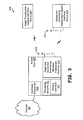
- FIG. 3 is a schematic block diagram of a wireless network infrastructure 305 that supports the adaptations of FIGs. 1 and 2, illustrating a wireless access point 307, single transmission capable device 369 and concurrent interfering transmission capable device 379.
- a wireless access point 307 receives a packet data packet from a packet data network.
- single transmission capable devices and concurrent interfering transmission capable devices with in a cell, such that the number of devices vary with time and create dynamically varying channel conditions, only one of each type are shown.
- Other factors that influence dynamically changing channel conditions include quality of service to each of the devices 369 and 379, priority services provided such as Voice over Internet Protocol (VoIP), idle states, interferences and noises within the cell.
- VoIP Voice over Internet Protocol
- the wireless access point 307 responds to these dynamically changing channel conditions by adapting concurrent interfering frame parameters.
- These frame parameters represent factors that include coding aggressiveness, that is, the number concurrent interfering transmission that are resolved during a frame period (or, a portion of frame period), and payload length.
- coding aggressiveness that is, the number concurrent interfering transmission that are resolved during a frame period (or, a portion of frame period)
- payload length a parameter that specifies the number concurrent interfering transmission that are resolved during a frame period (or, a portion of frame period)
- overhead associated with the increasing coding aggressiveness and increasing payload length are automatically taken into consideration to optimize the wireless access point 307 efficiency.
- the wireless access point 307 allocates a portion of contention free period to single transmission capable end point devices such as 369 that are only equipped with single transmission transceiver circuitries (not shown). During this period, neither the wireless access point 307 nor wireless end point devices equipped with concurrent interfering transmission circuitry perform concurrent interfering transmissions or receptions. Similarly, during contention period, the wireless access point 307 provides routing to all of the single transmission capable devices depending on contention from the wireless end point devices and arbitration, during separate potions of the period.
- the concurrent interfering transmission capable device 379 is equipped with single transceiver circuitry, concurrent interfering transceiver circuitry (described with reference to the FIG. 5).
- the wireless access point 307 allocates a second portion of contention free period to wireless end point devices that are equipped with both single transceiver circuitries and concurrent interfering transceiver circuitries, so that depending upon channel conditions single or concurrent interfering transmissions and receptions may be performed.
- the wireless access point 307 provides routing to the plurality of concurrent interfering transmission capable devices depending on contention from the wireless devices and arbitration, during separate potions of the period.
- Each of the frame may adapt one of many possible transmission modes, such as single transmission mode, a plurality of partial concurrent interfering transmission modes (say, partial concurrent interfering transmission modes a through n) and full concurrent interfering transmission mode. Similarly, during adaptation payload lengths are controlled.
- the wireless access point 307 divides both contention free period and contention period in to a predetermined number of sub-frames and adapts one of the single transmission mode, plurality of partial concurrent interfering transmission modes or full concurrent interfering transmission mode for each sub-frame.
- the duration of each sub-frame and payload lengths are controlled so as to optimize the wireless access point 307 efficiency, based upon channel conditions.
- Beacon signals generated by a primary controller 313 control the aspects of transmissions and receptions such as mode of transmission, contention free period accesses and contention period arbitrations. All associated wireless devices listen to beacon signals generated by the wireless access point 307 and plan their communication accordingly.
- a bridge circuitry (shown in FIG. 4) provides the wireless access point 307 ability to bridge with other wireless access points as well as bridge with Internet (or any other backbone network) 351 via an upstream transceiver 309.
- the wireless access point 307 and the concurrent interfering transmission capable wireless end point devices such as 379 may have a plurality of antennas such as 331 and a plurality of tuners, thus being capable of communicating in more than one radio channel.
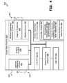
- FIG. 4 is a schematic block diagram 405 of a wireless access point 495 built in accordance with the embodiment of FIG. 3.
- the circuitry 495 may represent any of the wireless access points that route data packets.
- the wireless access point circuitry 495 generally includes central processing circuitry 409, local storage 411, user interfaces 413, upstream transceiver circuitry 421, bridging circuitry 425, wireless downstream transceiver circuitry 427 and primary downstream controller circuitry 481. These components communicatively coupled to one another via one or more of a system bus, dedicated communication pathways, or other direct or indirect communication pathways.
- the central processing circuitry 409 may be, in various embodiments, a microprocessor, a digital signal processor, a state machine, an application specific integrated circuit, a field programming gate array, or other processing circuitry.
- the primary downstream controller circuitry 481 may be a controller card or part of a wireless access point circuitry card containing a microcontroller or microprocessor.
- Local storage 411 may be random access memory, read-only memory, flash memory, a disk drive, an optical drive, or another type of memory that is operable to store computer instructions and data.
- the local storage 411 contains software components (not shown) that process received data in cases of both single transmission capable devices and concurrent interfering transmission capable devices. These software components utilize digital signal processing (information processing) techniques to provide concurrent interfering access to a plurality of concurrent interfering transmission capable end point devices, and also resolve plurality of concurrent interfering receptions in partial concurrent transmission modes and full concurrent transmission modes.
- the software components may include single transmission detection algorithm, single transmission algorithms, which assist in processing the data received from the single transmission capable devices and concurrent interfering transmission detection algorithms and concurrent interfering transmission algorithms which assist in processing the data received from the concurrent interfering transmission capable devices.
- the decisions regarding single and concurrent interfering transmissions portions during both contention period and contention free period are transmitted to the single transmission capable devices and concurrent interfering transmission capable devices during a beacon period, by the primary downstream controller circuitry 481.
- the primary downstream controller circuitry 481 informs about the duration of frame or each of the portions of frame, mode(s) and payload lengths to the associated devices, in either of an approach of entire frame or an approach of sub-frames.
- the primary downstream controller circuitry 481 determines the durations of these portions based upon the number of associated wireless end point devices within a cell, their capabilities, anticipated bandwidth usage, QOS (Quality Of Service) demands, and priority of service, idle states, cell overlap interferences, near-far interferences and noises.
- QOS Quality Of Service
- the beacon signals control the aspects of end point wireless devices that include mode of transmission, contention free period accesses and contention period arbitrations. All associated wireless end point devices listen to beacon signals and plan their communication accordingly.
- Stored end-point device capability information 491 assist primary downstream controller circuitry 481 in making decisions regarding adaptations to varying channel conditions.
- the primary downstream controller circuitry 481 contains controller storage 483.
- the controller storage 481 contains programming codes such as environmental assessment and mode determination 485 and single and concurrent interfering transceiver mode adaptation 487 that assist primary downstream controller circuitry 481 to determine a current channel condition, during an initial or a periodic assessment, and adapt the wireless downstream transceiver circuitry 427 mode accordingly.
- the wireless downstream transceiver circuitry 427 is equipped with an adaptive transmitter 429 and adaptive receiver 431 to handle the physical layer of protocol.
- the wireless downstream transceiver circuitry 427 is capable of performing both single transmission and receptions, and concurrent interfering transmission and receptions.
- the wireless downstream transceiver circuitry 427 is communicatively coupled to a plurality of antennas 437 that help communicate in multiple radio channels and a wider bandwidth.
- the software information processing components mentioned above with regards to the local storage 411 may exist in storage of wireless downstream transceiver circuitry 427, to facilitate faster processing.
- a bridge circuitry 425 allows bridging of the wireless access point 495 with other wireless access points as well as bridge with a backbone network via an upstream transceiver 421.
- the upstream transceiver circuitry 421 contains wired and wireless packet switched interfaces that provides the wireless access point ability to communicatively couple with a backbone network such as Internet, and is connected to a plurality of antennas 435 as well as a wire 433 that communicatively couples to the backbone network.
- the access point circuitry 495 of the present invention may include fewer or more components than are illustrated as well as lesser or further functionality.
- the illustrated wireless device is meant to merely offer one example of possible functionality and construction in accordance with the present invention.
- FIG. 5 is a schematic block diagram 505 of a wireless end point device 507 built in accordance with the embodiment of FIG. 3.
- the circuitry 507 may represent any of the wireless end point devices from which packets originate or within which packets terminate and may represent any of the concurrent interfering transmission capable wireless end point devices of FIG. 3.
- the wireless end point device 507 generally includes central processing circuitry 511, local storage 513, user interfaces 509, wireless transceiver circuitry 559 and communication interface 525. These components communicatively coupled to one another via one or more of a system bus, dedicated communication pathways, or other direct or indirect communication pathways.
- the central processing circuitry 511 may be, in various embodiments, a microprocessor, a digital signal processor, a state machine, an application specific integrated circuit, a field programming gate array, or other processing circuitry.
- the wireless transceiver circuitry 559 may consist of a local controller circuitry 561 containing a microcontroller or microprocessor.
- Local storage 513 may be random access memory, read-only memory, flash memory, a disk drive, an optical drive, or another type of memory that is operable to store computer instructions and data.
- the local storage 513 contains device operating system and application software 517 and single and concurrent interfering transceiver mode adaptation code 515.
- the communication interface 525 allows the wireless end point device 507 to interface with the wireless transceiver circuitry 559.
- the wireless transceiver circuitry 559 contains the local controller circuitry 561.
- the local controller circuitry 561 manages control functionality of wireless transceiver circuitry 559, by planning communication in one of single transmission mode, a plurality of partial-concurrent interfering transmission modes and full concurrent interfering transmission mode during any given frame or a portion of frame.
- the local controller circuitry 561 listens to the control signals during beacon period and adheres to the adapted frame characteristics.
- the control functionality of the wireless transceiver circuitry 559 include generating radio capability information and transmitting it to a wireless access point during a beacon period as well as receiving the control signals from an associated access point, interpreting it and plan communication accordingly.
- the wireless transceiver circuitry 559 is also equipped with an adaptive transmitter 565 and adaptive receiver 567.
- the wireless transceiver circuitry 559 is capable of performing both single transmission and receptions, and concurrent interfering transmission and receptions.
- FIG. 6 is an exemplary timing diagram 605 illustrating single, partial concurrent interfering and full concurrent interfering transmission modes, during contention free and contention periods, in the embodiment of FIG. 1.
- a frame contains a beacon period, contention free transmission period and contention period.
- a frame is adapted by varying duration of single transmission mode (refer to Frame A), one of partial concurrent interfering transmission modes a through n (refer to Frame B), and full concurrent interfering transmission mode (refer to Frame C). This is applicable to both contention free period and contention period, in case of single transmission mode and partial concurrent transmission modes.
- the payload length is also varied in accordance with channel conditions.
- the channel conditions are determined on the basis of number of associated wireless end point devices within the cell, their capabilities, anticipated bandwidth usage, QOS (Quality Of Service) demands, priority of service and idle states, cell overlap interferences, near-far interferences and noises.
- contention free period duration 611 and contention period duration 613 are varied in accordance with channel conditions, to optimize the performance of the wireless access point.
- contention free period duration 621 and contention period duration 623 are varied in accordance with channel conditions.
- the partial concurrent interfering transmission mode allows a limited number of wireless end point devices to transmit or receive data concurrently, and this occurs on the basis of channel being free for transmission or reception in contention free period and on the basis of contention and arbitration during contention period.
- the transmission period duration 631 is varied in accordance with channel conditions. In full concurrent interfering transmission mode, no restrictions are enforced on wireless end point devices to transmit and receive.
- the beacon signals that determine the accesses to wireless access point in various modes, during both contention free period and contention period, and are transmitted to the single transmissions capable devices and concurrent interfering transmissions capable devices during the beacon period.
- the access modes include both single transmissions mode, partial concurrent interfering transmission modes a through n, and full concurrent interfering transmissions mode.
- the decision to provide access in any mode and the duration of access depends on the wireless end point device capability and the wireless access point performance considerations.
- the beacon signals control the aspects of end point devices that include mode of transmission, contention free period accesses and contention period arbitrations. All associated wireless end point devices respond to the beacon signals and plan their communication accordingly.
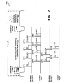
- FIG. 7 is a timing diagram 705 illustrating receptions during a contention free period of a partial concurrent interfering transmission mode of FIG. 6.
- the illustration shows Frame B of FIG. 6, wherein one of the partial concurrent interfering modes (say, mode n) is adapted during the contention free period.
- the illustration also shows two wireless end point devices, wireless device X and wireless device Y, transmitting data concurrently to the wireless access point.
- a beacon period precedes the contention free period.
- the beacon signals that determine the transmission to and receptions from the wireless access point in various modes during contention free period are transmitted to the single transmission capable devices and concurrent interfering transmission capable devices during the beacon period.
- the decision regarding partial concurrent interfering transmission mode n is transmitted during this beacon period, and depends primarily on the wireless device capability and the channel conditions.
- the beacon signals control the aspects of end point wireless devices that include mode of transmission, contention free period accesses and contention period arbitrations. All associated wireless end point devices respond to the beacon signals and plan their communication accordingly.
- the contention free period begins by providing a portion of the Frame B for few of the concurrent interfering transmission capable devices.
- the concurrent interfering transmission capable devices X and Y (such as the 379 of FIG. 3), sense channel being idle for a SIFS duration and transmit data to the access point, concurrently.
- the data transmission from the concurrent interfering transmission capable wireless devices is based upon acknowledgement after transfer of data, as illustrated. Similar considerations apply for transmission of data from the access point to the concurrent interfering transmission capable wireless devices.
- FIG. 8 is a timing diagram 805 illustrating receptions during a contention period of a partial concurrent interfering transmission mode of FIG. 6.
- the illustration shows Frame B of FIG. 6, wherein one of the partial concurrent interfering modes (say, mode n) is adapted during the contention period.
- the illustration also shows two wireless end point devices, wireless device X and wireless device Z, transmitting data concurrently to the wireless access point.
- the decisions regarding partial concurrent interfering transmission mode n and contention period are transmitted during the beacon period, and depends primarily on the wireless device capability and the channel conditions.
- contention period begins by providing a portion of the Frame B for few of the concurrent interfering transmission capable devices, on the basis of contention.
- the concurrent interfering transmission capable end point wireless devices (such as the wireless device X and Y) sense Distributed coordination function Inter Frame Space (DIFS) and transmits RTS signal.
- DIFS Distributed coordination function Inter Frame Space
- the wireless access point responds by sending a CTS signal.
- the concurrent interfering transmission capable end point wireless devices send data and receive ACK in response.
- FIG. 9 is an exemplary timing diagram 905 illustrating single, partial concurrent interfering and full concurrent interfering transmission modes, using a sub-frame approach, in the embodiment of FIG. 2.
- the illustration shows a frame (Frame A) containing a beacon period, contention free transmission period and contention period.
- the frame A is adapted by dividing it into sub-frames and varying duration of the sub-frames. This is applicable to both contention free period and-contention period, in case of single transmission mode and partial concurrent transmission modes.
- the payload length is also varied in accordance with channel conditions.
- contention free period containing sub-frames such as ST (Single Transmission) mode 911, PCIT (Partial Concurrent Interfering Transmission) mode a 913, PCIT mode b 915, PCIT mode n 917 and full concurrent interfering transmission mode 919.
- contention period contains sub-frames such as PCIT mode b 931, PCIT mode n 933, full concurrent interfering transmission mode 935, PCIT mode a 937 and ST mode 939.
- the modes, mode durations and payload lengths are varied in accordance with channel conditions.
- the channel conditions are determined on the basis of number of associated wireless end point devices within the cell, their capabilities, anticipated bandwidth usage, QOS (Quality Of Service) demands, priority of service and idle states, cell overlap interferences, near-far interferences and noises.
- QOS Quality Of Service
- the wireless access point determines the transmission modes applicable for each of the sub-frames, during both contention free period and contention period, and transmits it to the single transmissions capable devices and concurrent interfering transmissions capable devices during the beacon period.
- the access modes include both single transmissions mode, partial concurrent interfering transmission modes a through n, and full concurrent interfering transmissions mode. The selection of mode and the duration of access in each sub-frame depend on the wireless end point device capability and the wireless access point performance considerations.
- circuit and “circuitry” as used herein may refer to an independent circuit or to a portion of a multifunctional circuit that performs multiple underlying functions.
- processing circuitry may be implemented as a single chip processor or as a plurality of processing chips.
- a first circuit and a second circuit may be combined in one embodiment into a single circuit or, in another embodiment, operate independently perhaps in separate chips.
- chip refers to an integrated circuit. Circuits and circuitry may comprise general or specific purpose hardware, or may comprise such hardware and associated software such as firmware or object code.
- operably coupled and “communicatively coupled,” as may be used herein, include direct coupling and indirect coupling via another component, element, circuit, or module where, for indirect coupling, the intervening component, element, circuit, or module does not modify the information of a signal but may adjust its current level, voltage level, and/or power level.
- inferred coupling i.e., where one element is coupled to another element by inference
- inferred coupling includes direct and indirect coupling between two elements in the same manner as “operably coupled” and "communicatively coupled.”
Landscapes
- Engineering & Computer Science (AREA)
- Quality & Reliability (AREA)
- Computer Networks & Wireless Communication (AREA)
- Signal Processing (AREA)
- Mobile Radio Communication Systems (AREA)
Applications Claiming Priority (2)
| Application Number | Priority Date | Filing Date | Title |
|---|---|---|---|
| US11/595,346 US8194587B2 (en) | 2006-11-09 | 2006-11-09 | Adaptive network supporting single to concurrent interfering wireless transmissions |
| US11/641,198 US20080112375A1 (en) | 2006-11-09 | 2006-12-18 | Wireless network that adapts concurrent interfering transmission parameters based on channel conditions |
Publications (1)
| Publication Number | Publication Date |
|---|---|
| EP1921787A2 true EP1921787A2 (de) | 2008-05-14 |
Family
ID=39148622
Family Applications (1)
| Application Number | Title | Priority Date | Filing Date |
|---|---|---|---|
| EP07018846A Withdrawn EP1921787A2 (de) | 2006-11-09 | 2007-09-25 | Drahtloses Netzwerk, das basierend auf den Kanalbedingungen gleichzeitige Interferenzübertragungsparameter adaptiert |
Country Status (4)
| Country | Link |
|---|---|
| US (1) | US20080112375A1 (de) |
| EP (1) | EP1921787A2 (de) |
| KR (1) | KR100915366B1 (de) |
| TW (1) | TW200838177A (de) |
Families Citing this family (12)
| Publication number | Priority date | Publication date | Assignee | Title |
|---|---|---|---|---|
| US8208392B2 (en) * | 2007-08-13 | 2012-06-26 | Samsung Electronics Co., Ltd. | System and method for peer-to-peer beam discovery and communication in infrastructure based wireless networks using directional antennas |
| US8917675B2 (en) * | 2007-08-20 | 2014-12-23 | Samsung Electronics Co., Ltd. | System and method for multiple contention access periods |
| US8817676B2 (en) * | 2008-11-03 | 2014-08-26 | Samsung Electronics Co., Ltd. | Method and system for station-to-station directional wireless communication |
| US8385362B2 (en) * | 2009-01-09 | 2013-02-26 | Samsung Electronics Co., Ltd. | Method and system for contention-based medium access schemes for directional wireless transmission with asymmetric antenna system (AAS) in wireless communication systems |
| EP2863691A1 (de) | 2009-10-28 | 2015-04-22 | Electronics and Telecommunications Research Institute | Stromsparverfahren in einem drahtlosen Kommunikationssystem |
| PT104868A (pt) * | 2009-12-10 | 2011-06-14 | Univ Aveiro | Método e aparelho para captura determinística de um canal de comunicação partilhado entre tecnologias baseadas em contenção |
| DK2642681T3 (en) | 2011-09-30 | 2015-02-16 | Goertek Inc | Wireless digital communication method and system |
| US9008062B2 (en) * | 2012-01-09 | 2015-04-14 | Futurewei Technologies, Inc. | Systems and methods for AP discovery with FILS beacon |
| US9646626B2 (en) * | 2013-11-22 | 2017-05-09 | At&T Intellectual Property I, L.P. | System and method for network bandwidth management for adjusting audio quality |
| CN103781158A (zh) | 2013-11-30 | 2014-05-07 | 北京智谷睿拓技术服务有限公司 | 无线网络接入方法及接入装置 |
| CN105517181B (zh) * | 2014-09-25 | 2020-05-15 | 中兴通讯股份有限公司 | 非授权载波的载波资源处理方法、装置及传输节点 |
| EP3205168A4 (de) | 2014-10-10 | 2017-09-06 | Samsung Electronics Co., Ltd. | System und verfahren zur erkennung verborgener knoten in zellularen systemen auf nichtlizenzierten bändern |
Family Cites Families (14)
| Publication number | Priority date | Publication date | Assignee | Title |
|---|---|---|---|---|
| JP2000502222A (ja) * | 1995-12-07 | 2000-02-22 | ビスター・テレコミュニケーションズ・インコーポレイテッド | 無線パケットデータ分配通信システム |
| EP0831612B1 (de) * | 1996-03-15 | 2009-06-17 | Ntt Mobile Communications Network Inc. | Mobiles nachrichtenübertragungssystem |
| GB0107578D0 (en) * | 2001-03-27 | 2001-05-16 | Koninl Philips Electronics Nv | Radio communication system |
| US7170876B2 (en) * | 2002-04-30 | 2007-01-30 | Qualcomm, Inc. | Outer-loop scheduling design for communication systems with channel quality feedback mechanisms |
| US8208364B2 (en) * | 2002-10-25 | 2012-06-26 | Qualcomm Incorporated | MIMO system with multiple spatial multiplexing modes |
| KR100524378B1 (ko) * | 2002-11-20 | 2005-10-31 | 한국전자통신연구원 | 다중 빔 위성을 이용한 셀룰러 이동통신시스템에서의적응형 패킷 전송 방법 |
| US8054798B2 (en) * | 2003-06-13 | 2011-11-08 | Ntt Docomo, Inc. | Proxy active scan for wireless networks |
| KR100943624B1 (ko) * | 2003-09-15 | 2010-02-24 | 삼성전자주식회사 | 직교 주파수 분할 다중 통신 시스템에서 동적 자원 할당장치 및 방법 |
| US20050111419A1 (en) * | 2003-11-20 | 2005-05-26 | Samsung Electronics Co., Ltd. | Method of performing communication over wireless network including multiple input/multiple output stations |
| US7206550B2 (en) * | 2003-12-29 | 2007-04-17 | Intel Corporation | Antenna subsystem calibration apparatus and methods in spatial-division multiple-access systems |
| JP4086304B2 (ja) * | 2004-04-23 | 2008-05-14 | 株式会社東芝 | 通信装置、通信システム、および通信制御プログラム |
| EP1784652A4 (de) * | 2004-08-16 | 2010-05-12 | Qualcomm Inc | Verfahren und vorrichtung zum senden von gruppenkommunikationssignalen |
| US7463592B2 (en) * | 2004-12-03 | 2008-12-09 | Microsoft Corporation | Protocol for exchanging control data to mitigate interference problems in wireless networking |
| US8750908B2 (en) * | 2005-06-16 | 2014-06-10 | Qualcomm Incorporated | Quick paging channel with reduced probability of missed page |
-
2006
- 2006-12-18 US US11/641,198 patent/US20080112375A1/en not_active Abandoned
-
2007
- 2007-09-25 EP EP07018846A patent/EP1921787A2/de not_active Withdrawn
- 2007-11-08 KR KR1020070113807A patent/KR100915366B1/ko not_active Expired - Fee Related
- 2007-11-09 TW TW096142530A patent/TW200838177A/zh unknown
Also Published As
| Publication number | Publication date |
|---|---|
| KR100915366B1 (ko) | 2009-09-03 |
| TW200838177A (en) | 2008-09-16 |
| KR20080042728A (ko) | 2008-05-15 |
| US20080112375A1 (en) | 2008-05-15 |
Similar Documents
| Publication | Publication Date | Title |
|---|---|---|
| EP1921787A2 (de) | Drahtloses Netzwerk, das basierend auf den Kanalbedingungen gleichzeitige Interferenzübertragungsparameter adaptiert | |
| US8126396B2 (en) | Wireless network that utilizes concurrent interfering transmission and MIMO techniques | |
| US12348987B2 (en) | Optimization of distributed Wi-Fi networks | |
| EP3430832B1 (de) | Optimierung von verteilten wifi-netzwerken | |
| KR102161973B1 (ko) | 스테이션, 통신 방법 및 집적 회로 | |
| CN1630294B (zh) | 在能够执行网络通信的设备上无线传输干扰的避免 | |
| US7778170B2 (en) | Spectrum and medium access allocation for fairness | |
| US7809399B2 (en) | Method and device for providing multiple communication protocols with a single transceiver | |
| TW200525940A (en) | Wireless local area network (WLAN) methods and components that utilize traffic prediction | |
| US7466676B2 (en) | Method and apparatus for multi-channel MAC protocol using multi-tone synchronous collision resolution | |
| KR100585296B1 (ko) | 무선 개인영역 네트워크에서의 저전력 전송장치 및 그전송방법 | |
| US20090147678A1 (en) | Systems and methods for traffic flow based rate adaptation in packet-based networks | |
| WO2012016187A2 (en) | Distributed rate allocation and collision detection in wireless networks | |
| KR20080015757A (ko) | 동일한 주파수 대역에서 동작하는 다중 무선 콤퍼넌트들의공존을 가능하게 하기 위한 시스템들 및 방법들 | |
| CN102217395A (zh) | 无线通信系统中用于信道预留的装置和方法 | |
| CN108141886A (zh) | 用于连接对象与网关之间的无线通信的方法和设备 | |
| WO2009146613A1 (en) | Transmit power control for dynamic spectrum access | |
| US20060209712A1 (en) | Wireless communication system, wireless communication apparatus, wireless communication method, and computer program | |
| CN1965503B (zh) | 用于操作彼此邻近的不同收发器的系统和方法 | |
| EP1921786A2 (de) | Simultane und unterschiedliche gleichzeitige Interferenzübertragungsparameter und Techniken unterstützende Zelle | |
| US20080112358A1 (en) | Cell protocol adapting between single and concurrent interfering transmissions and receptions based on channel conditions | |
| CN101207541A (zh) | 支持多个终端设备的接入点电路及其方法 | |
| US8194587B2 (en) | Adaptive network supporting single to concurrent interfering wireless transmissions | |
| JP2008537384A (ja) | 無線多重アクセスのためのアクセスポイント及び方法 | |
| US20090080395A1 (en) | Mobile communication system, base station device, and mobile communication method |
Legal Events
| Date | Code | Title | Description |
|---|---|---|---|
| PUAI | Public reference made under article 153(3) epc to a published international application that has entered the european phase |
Free format text: ORIGINAL CODE: 0009012 |
|
| AK | Designated contracting states |
Kind code of ref document: A2 Designated state(s): AT BE BG CH CY CZ DE DK EE ES FI FR GB GR HU IE IS IT LI LT LU LV MC MT NL PL PT RO SE SI SK TR |
|
| AX | Request for extension of the european patent |
Extension state: AL BA HR MK RS |
|
| STAA | Information on the status of an ep patent application or granted ep patent |
Free format text: STATUS: THE APPLICATION IS DEEMED TO BE WITHDRAWN |
|
| 18D | Application deemed to be withdrawn |
Effective date: 20120403 |