EP1921742A2 - Système de conversion d'alimentation extensible et modulaire pour avion - Google Patents
Système de conversion d'alimentation extensible et modulaire pour avion Download PDFInfo
- Publication number
- EP1921742A2 EP1921742A2 EP20070120304 EP07120304A EP1921742A2 EP 1921742 A2 EP1921742 A2 EP 1921742A2 EP 20070120304 EP20070120304 EP 20070120304 EP 07120304 A EP07120304 A EP 07120304A EP 1921742 A2 EP1921742 A2 EP 1921742A2
- Authority
- EP
- European Patent Office
- Prior art keywords
- power conversion
- power
- conversion module
- modules
- controls
- Prior art date
- Legal status (The legal status is an assumption and is not a legal conclusion. Google has not performed a legal analysis and makes no representation as to the accuracy of the status listed.)
- Withdrawn
Links
Images


Classifications
-
- H—ELECTRICITY
- H02—GENERATION; CONVERSION OR DISTRIBUTION OF ELECTRIC POWER
- H02M—APPARATUS FOR CONVERSION BETWEEN AC AND AC, BETWEEN AC AND DC, OR BETWEEN DC AND DC, AND FOR USE WITH MAINS OR SIMILAR POWER SUPPLY SYSTEMS; CONVERSION OF DC OR AC INPUT POWER INTO SURGE OUTPUT POWER; CONTROL OR REGULATION THEREOF
- H02M7/00—Conversion of ac power input into dc power output; Conversion of dc power input into ac power output
- H02M7/66—Conversion of ac power input into dc power output; Conversion of dc power input into ac power output with possibility of reversal
- H02M7/68—Conversion of ac power input into dc power output; Conversion of dc power input into ac power output with possibility of reversal by static converters
- H02M7/72—Conversion of ac power input into dc power output; Conversion of dc power input into ac power output with possibility of reversal by static converters using discharge tubes with control electrode or semiconductor devices with control electrode
- H02M7/79—Conversion of ac power input into dc power output; Conversion of dc power input into ac power output with possibility of reversal by static converters using discharge tubes with control electrode or semiconductor devices with control electrode using devices of a triode or transistor type requiring continuous application of a control signal
- H02M7/81—Conversion of ac power input into dc power output; Conversion of dc power input into ac power output with possibility of reversal by static converters using discharge tubes with control electrode or semiconductor devices with control electrode using devices of a triode or transistor type requiring continuous application of a control signal arranged for operation in parallel
-
- F—MECHANICAL ENGINEERING; LIGHTING; HEATING; WEAPONS; BLASTING
- F02—COMBUSTION ENGINES; HOT-GAS OR COMBUSTION-PRODUCT ENGINE PLANTS
- F02N—STARTING OF COMBUSTION ENGINES; STARTING AIDS FOR SUCH ENGINES, NOT OTHERWISE PROVIDED FOR
- F02N11/00—Starting of engines by means of electric motors
- F02N11/08—Circuits or control means specially adapted for starting of engines
- F02N11/0862—Circuits or control means specially adapted for starting of engines characterised by the electrical power supply means, e.g. battery
-
- H—ELECTRICITY
- H05—ELECTRIC TECHNIQUES NOT OTHERWISE PROVIDED FOR
- H05K—PRINTED CIRCUITS; CASINGS OR CONSTRUCTIONAL DETAILS OF ELECTRIC APPARATUS; MANUFACTURE OF ASSEMBLAGES OF ELECTRICAL COMPONENTS
- H05K7/00—Constructional details common to different types of electric apparatus
- H05K7/14—Mounting supporting structure in casing or on frame or rack
- H05K7/1422—Printed circuit boards receptacles, e.g. stacked structures, electronic circuit modules or box like frames
- H05K7/1427—Housings
- H05K7/1432—Housings specially adapted for power drive units or power converters
- H05K7/14325—Housings specially adapted for power drive units or power converters for cabinets or racks
-
- F—MECHANICAL ENGINEERING; LIGHTING; HEATING; WEAPONS; BLASTING
- F02—COMBUSTION ENGINES; HOT-GAS OR COMBUSTION-PRODUCT ENGINE PLANTS
- F02N—STARTING OF COMBUSTION ENGINES; STARTING AIDS FOR SUCH ENGINES, NOT OTHERWISE PROVIDED FOR
- F02N11/00—Starting of engines by means of electric motors
- F02N11/04—Starting of engines by means of electric motors the motors being associated with current generators
-
- F—MECHANICAL ENGINEERING; LIGHTING; HEATING; WEAPONS; BLASTING
- F02—COMBUSTION ENGINES; HOT-GAS OR COMBUSTION-PRODUCT ENGINE PLANTS
- F02N—STARTING OF COMBUSTION ENGINES; STARTING AIDS FOR SUCH ENGINES, NOT OTHERWISE PROVIDED FOR
- F02N11/00—Starting of engines by means of electric motors
- F02N11/08—Circuits or control means specially adapted for starting of engines
- F02N2011/0881—Components of the circuit not provided for by previous groups
- F02N2011/0896—Inverters for electric machines, e.g. starter-generators
Definitions
- the present invention relates to power conversion systems, and more particularly to a method and apparatus for a modular and scalable power conversion system for an aircraft.
- Electric systems used in complex environments such as aerospace systems, more electric aircraft systems, industrial environments, vehicles, etc., include a large number of electric systems and modules.
- various electric systems and modules may need to be connected to electric power sources, disconnected from electric power sources, maintained in a powered-up state, etc., at various times.
- various electric systems and modules in a complex environment may require different amounts and type of electrical power.
- some electric systems and modules may require DC power while others may require AC power.
- Some electric systems and modules may require 28Vdc, others 230Vac, yet others 115Vac at 400Hz.
- the power levels required by various parts of a complex environment may also depend on the operational stage of the environment. For example, different levels of power may be needed during a start-up and during a continuous operation of a complex environment, such as an aircraft.
- Aircraft are currently being designed to use less non-electric power (such as hydraulic and pneumatic power) and more electrical power.
- Aircraft system architectures that rely solely, or to a great extent, on electrical power, are also referred to as More Electric Aircraft (MEA) system architectures.
- MEA system architectures use starter-generators to start the aircraft main engines, as well as supply electrical power to various system loads that may utilize electrical power at various frequencies and voltages.
- MEA system architectures, and/or starter-generators currently used to power MEA system architectures typically include relatively complex power electronics circuits with large weight.
- motor controllers are used for main engine start and after the start, to supply the motors in the Environmental Control System (ECS) or other motor loads in the aircraft systems, such as hydraulic system loads.
- ECS Environmental Control System
- an electric power distribution system includes AC generators.
- High voltage AC power can be converted to high voltage DC power by one or more AC-to-DC conversion devices, such as auto transformer rectifier units (ATRUs), that receive AC power from AC busses.
- ATRUs auto transformer rectifier units
- the power distribution system provides high voltage AC and DC power to support conventional 115V and 28Vdc bus architectures.
- An output from an ATRU is alternatively connected to an AC generator during start, and to a load such as an air compressor system, during normal operation.
- Disclosed embodiments of this application address these and other issues by utilizing a modular and scalable power conversion system consisting of power conversion modules, which are designed and optimized for continuous operation when they supply motors used in aircraft systems, or aircraft busses with fixed frequency.
- a number of power conversion modules are operated in parallel and used to supply start power to a starter generator.
- the power conversion modules may be controlled for connection to any starter generator or motor in the electric system, hence allowing for power conversion modules to be designed for much lower ratings, to realize weight, volume and cost savings.
- the availability of the start system is increased over previous systems, because a failure of one of the power conversion modules used in parallel during start will remove only partially the start capability, as the other connected power conversion modules are able to supply start power.
- a power conversion apparatus comprises: a plurality of power conversion modules, the plurality of power conversion modules being optionally controllable to function independently of each other to supply a plurality of systems, function in an inter-relational mode in which at least one power conversion module from the plurality of power conversion modules drives a system and, upon a failure of the at least one power conversion module, at least another power conversion module from the plurality of power conversion modules will drive the system, and function in a scalable mode in which at least two power conversion modules of the plurality of power conversion modules are connected to provide an additive output.
- a power conversion module comprises: an input assembly; a 3 phase bridge; an output assembly including at least one isolation device; and a control unit, wherein the control unit controls the 3 phase bridge via a driver, and controls a state of at least one isolation device within the output assembly.
- a method for converting power comprises: controlling a plurality of power conversion modules to function independently of each other to supply a plurality of systems; controlling the plurality of power conversion modules to function in an inter-relational mode in which at least one power conversion module from the plurality of power conversion modules drives a system and, upon a failure of the at least one power conversion module, at least another power conversion module from the plurality of power conversion modules will drive the system; and controlling the plurality of power conversion modules to function in a scalable mode in which at least two power conversion modules of the plurality of power conversion modules are connected to provide an additive output.
- FIG. 1 is a general block diagram of an electrical system to which principles of the present invention can be applied according to an embodiment of the present invention
- FIG. 2 is a block diagram of a typical/ conventional power system for an aircraft
- FIG. 3 is a block diagram of a modular and scalable power conversion system for aircraft according to an embodiment of the present invention
- FIG. 4A is a block diagram of a system including two power conversion modules connected in parallel to supply power to a starter generator according to an embodiment of the present invention illustrated in FIG. 3;
- FIG. 4B is a block diagram of an exemplary modular and scalable power conversion system for aircraft according to an embodiment of the present invention illustrated in FIG. 3;
- FIG. 4C is a block diagram of another exemplary modular and scalable power conversion system for aircraft according to an embodiment of the present invention illustrated in FIG. 3;
- FIG. 5 is a block diagram illustrating an implementation for a power conversion module for a modular and scalable power conversion system for aircraft according to an embodiment of the present invention illustrated in FIG. 3.
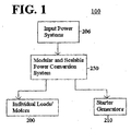
- FIG. 1 is a general block diagram of an electrical system to which principles of the present invention can be applied according to an embodiment of the present invention.
- the electrical system 100 illustrated in FIG.1 includes the following components: input power systems 206; a modular and scalable power conversion system 250; individual loads/ motors 200; and starter generators 210. Operation of the electrical system 100 in FIG. 1 will become apparent from the following discussion.
- Electrical system 100 may be associated with environments with electrical components such as a cabin air compressor system, a hydraulic system, a heating system, a traction system, etc., in an aircraft, a ship, a train, a laboratory facility, etc.
- Input power systems 206 provide electrical power to individual loads/ motors 200 and starter generators 210, through the modular and scalable power conversion system 250.
- Input power systems 206 handle wattage power that can be on the order of W, kW, hundreds of kW, MW, etc., and voltages that can be on the order of Volts, hundreds to thousands of Volts, etc.
- the outputs of input power systems 206 may be DC voltages, AC voltages, etc.
- Input power systems 206 may include motors, turbines, generators, transformers, filters, circuit breakers, etc.
- Modular and scalable power conversion system 250 receives power from input power systems 206, and provides electrical power to individual loads/ motors 200 and starter generators 210.
- Modular and scalable power conversion system 250 includes power conversion modules.
- Modular and scalable power conversion system 250 may also include other electrical circuits and components such as transformers, rectifiers, filters, battery banks, etc., magnetic components such as coils and permanent magnets, etc.
- Individual loads/ motors 200 and starter generators 210 are systems that enable functioning of services onboard a vehicle, in an aircraft, in a lab, etc.
- Individual loads/ motors 200 and starter generators 210 may include an air conditioning system, a navigation system, an aircraft control system, a cabin air compressor, a starter generator, a braking system, etc.
- Input power systems 206 and modular and scalable power conversion system 250 may provide, and individual loads/ motors 200 and starter generators 210 may use various AC or DC voltages.
- some electrical systems may utilize AC voltages of 115V or 230V or higher, with fixed frequencies (such as, for example, 50/60 Hz or 400Hz), or variable frequencies (such as, for example 360-800Hz for aerospace applications, 1000-2000Hz for high frequency), or DC voltages such as, for example, 28V, 270V, or ⁇ 270V.
- FIG. 2 is a block diagram of a typical/ conventional power system 204 for an aircraft.
- a motor controller 207 is used to supply power to the starter generator 210M for main engine start.
- motor controller 207 is used to supply a motor 213.
- the motor 213 may be included in the ECS, in the hydraulic aircraft system, etc.
- the typical/ conventional aircraft power system 204 imposes design constraints on the generating and conversion equipment that includes motor controller 207. Design constraints are imposed on the motor controller 207 because its design is heavily dependent the power required to achieve the main engine start at starter generator 210M.
- the output current required for main engine start is typically 2 to 5 times larger than the current required to drive the motor 213.
- FIG. 3 is a block diagram of a modular and scalable power conversion system 250A for aircraft according to an embodiment of the present invention.
- modular and scalable power conversion system 250A includes n power conversion modules (PCMs) 130_1, 130_2, ..., 130_n.
- the PCMs are designed and optimized for continuous operation when they supply the loads/motors 200_1, 200_2, ..., 200_n used in aircraft systems, such as the ECS, the hydraulic system, etc.
- a certain number of PCMs 130_1, 130_2, ..., 130_n are operated in parallel and used to supply the start power to a starter generator (SG) 210_1.
- SG starter generator
- the aircraft electrical architecture allows to connect each of the PCMs 130_1, 130_2, ..., 130_n to any of the SGs in the electric system, such as SG 210_1, ..., 210_m, as required for main engine start, auxiliary power unit (APU) start, etc.
- This approach allows for the PCMs 130_1, 130_2,..., 130_n to be designed for a much lower rating, hence realizing weight, volume and cost savings.
- Each one of the power conversion modules (PCMs) 130_1, 130_2, ..., 130_n can be designed to have independent power output and controls.
- the independent controls capability of the PCMs is used during the continuous operation, when the PCM modules supply power to individual loads and motors, such as ECS motors, hydraulic system motors, other aircraft systems, etc.
- the PCMs 130_1, 130_2, ..., 130_n also include the capability and the interfaces required to communicate with each other, to use common controls during the main engine start, when the outputs of the PCMs are paralleled.
- main engine start when a certain number of PCMs are operated in parallel and used to supply the start power to a starter generator among 210_1, 210_2, ..., 210_m, two or more PCMs use the same controls supplied via a controls and communication interface 255.
- One of the PCM is the master and the other PCM(s) is/are the slave(s). In case the master PCM has a failure, it will be turned off and one of the remaining PCM controllers will become master and continue the start.
- the controls and communication interface 255 manages the PCM hierarchy based on PCM functionality.
- the PCMs 130_1, 130_2, ..., 130_n may control connections/switch arrangement for contactors 302_1a, 302_1b, 302_2a, 302_2b, ..., 302_na, 302_nb to enable combinations of different PCMs to be connected to a starter generator and at the same time to be disconnected from any individual loads.
- Contactors 302_1a, 302_1b, 302_2a, 302_2b, ..., 302_na, 302_nb may, alternatively or additionally, be controlled by the controls and communication interface 255.
- connections/switch arrangement for contactors 302_1a, 302_1b, 302_2a, 302_2b, ..., 302_na, 302_nb may be controlled to establish an independent PCM configuration, or an interdependent PCM configuration such as, for example, a paralleled PCM configuration.
- the contactors 302_1a, 302_1b, 302_2a, 302_2b, ..., 302_na, 302_nb may be separate units from PCMs 130_1, 130_2, ..., 130_n, or may be included in the PCMs 130_1, 130_2, ..., 130_n.
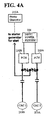
- FIG. 4A is a block diagram of a system including two power conversion modules connected in parallel to supply power to a starter generator according to an embodiment of the present invention illustrated in FIG. 3.
- a start converter may have dual use as a motor controller, by powering a starter generator and a cabin air compressor (CAC) load sequentially.
- CAC cabin air compressor
- a start converter used to power both a starter generator and a CAC load uses a large amount of power and is inefficiently used, because the start function for a starter generator typically requires power on the order of 100kW, while a CAC load start function requires less power than the starter generator.
- the excess power capacity corresponding to the starter generator is not used when the start converter powers a CAC load, and the start converter is typically oversized for the use of powering a CAC.
- two PCMs 130A and 130B are operated in parallel to provide power to a starter generator 210A for start.
- the PCMs 130A and 130B are operated independently of each other, to provide power to CAC 1 (213B) and CAC 2 (213A).
- the output of the two PCMs 130A and 130B are combined during start of the system to obtain a larger start power (for starter generator 210A), and are decoupled after start, to obtain smaller powers (for loads 213A and 213B).
- PCMs 130A and 130B instead of using a fixed 100kW power controller to power a 100kW starter generator and a 50kW CAC, PCMs 130A and 130B, which provide 50kW each, output 100kW power for starter generator 210A when the PCMs 130A and 130B are operated together in parallel, and output 50kW each for 2 separate loads, when the PCMs 130A and 130B are operated independently. Weight and volume system savings are hence achieved.
- FIG. 4B is a block diagram of an exemplary modular and scalable power conversion system for aircraft according to an embodiment of the present invention illustrated in FIG. 3.
- PCMs 130A and 130B are operated with their outputs in parallel during a main engine start with starter generator 210_L1, with PCMs 130A and 130B being controlled by a common control algorithm.
- the two contactors closer to the PCM at the output of each PCM module are closed. This contactor arrangement allows for start operation using one PCM module in the case of failure of the other module.
- contactors 302A and 302B are open and the contactor connection to Cabin Air Compressor (CAC) 1 (contactor 302D) and CAC 2 (contactor 302C) are closed.
- CAC Cabin Air Compressor
- PCMs 130A and 130B are now operated independently, each supplying one CAC of the ECS, CAC 1 and 2 (213A and 213B).
- PCMs 130A and 130B are designed for continuous operation to drive the CAC 1 and CAC 2 (213A and 213B) and therefore weight and volume savings are realized.
- PCMs 130C and 130D are operated with their outputs in parallel during a main engine start using starter generator 210_L2, or starter generator 210_R1, or auxiliary starter generator 210A, and are controlled by a common control algorithm. After the start, PCMs 130C and 130D are operated independently, each supplying a motor driving the hydraulic system (215A and 215B).
- PCMs 130E and 130F are also operated with their outputs in parallel during a main engine start using starter generator 210_R2 and are controlled by a common control algorithm. After the start, PCMs 130E and 130F are operated independently, each supplying a CAC load (213C and 213D).
- General motor controllers 207A, 207B, 207C, and 207D are also present. Each general motor controller supplies only one load, such as: a condenser fan 213E, a vapor cycle system (VCS) 213G, a VCS 213H, and a condenser fan 213F.
- a condenser fan 213E a condenser fan 213E
- VCS vapor cycle system
- VCS vapor cycle system
- condenser fan 213F condenser fan
- the availability of the start system illustrated in FIG. 4B is increased, since the left engine start capability is 200% when both starter generators (210_L1 and 210_L2) and all four PCMs 130A, 130B, 130C, and 130D are available.
- the left engine start capability will degrade from 200% to 150% when any one of the PCMs 130A, 130B, 130C, and 130D fails.
- the left engine start capability will degrade to 100% when two PCMs among 130A, 130B, 130C, and 130D fail.
- the 150% engine start capability and availability step is non-existent.
- the aircraft system can withstand more failures than a typical system with 2 generators and 2 start converters (one per generator). Using systems implemented in the current application, engine start can still be performed with a failed generator or any combination of 2 failed PCMs.
- the PCMs in FIGS. 3, 4A and 4B may include Multiple Function Power Converters (MFPCs), described in the non-provisional application titled "An Architecture and a Multiple Function Power Converter for Aircraft", the entire contents of which are hereby incorporated by reference.
- MFPCs Multiple Function Power Converters
- the PCMs can perform multiple functions, including functions of motor controllers, functions of static inverters, and functions of start converters, as illustrated in FIG. 4C.
- MFPCs 130_1a and 130_1b are used in parallel to starter generator 210_L1, and are used afterwards to provide power to CAC 213A and 213B.
- MFPCs 130_2a and 130_2b are used in parallel to starter generator 210_R2, and are used afterwards to provide power to CAC 213C and 213D.
- MFPCs 130_3a and 130_3b are used in parallel to provide power to starter generators 210_L2 and 210_R1, and are used afterwards to provide power to hydraulic loads 215A and 215B, and to 400Hz loads 218A and 218B through left and right autotransformers (OAT) 291A and 291B.
- 400 Hz is one of the standard frequencies used in aircraft electrical systems. While 400Hz loads are shown in FIG. 4C, loads using other frequencies can also receive conditioned power from the MFPCs.
- MFPCs may provide power to loads using other constant or variable frequencies, such as loads associated with MEA aircraft.
- the MFPCs in FIG. 4C perform functions for electric engine start, for driving the ECS or cabin air compressors, and functions of static inverters.
- the MFPCs provide 115VAC or 230VAC, 3-phase, 400Hz (or other standard frequencies used in aircraft electrical systems) electrical power for aircraft systems and equipment that require such power.
- Aircraft wiring saving may be achieved by using the generator main feeders during engine start, thus eliminating the need for dedicated feeders for start. Since MFPCs can perform the functions of motor controllers, start converters, and inverters, a reduced number of MFPCs is sufficient to power a variety of loads.
- FIG. 5 is a block diagram illustrating an implementation for a power conversion module (PCM) 130A for a modular and scalable power conversion system for aircraft according to an embodiment of the present invention illustrated in FIG. 3.
- a PCM 130A includes: an input assembly 301; a 3 phase bridge 303; an output assembly 305; drivers 307; and power conversion module (PCM) controls 309.
- Input power passes through the input assembly 301, the 3 phase bridge 303, and the output assembly 305, from which output power is obtained.
- Input signals and control power are received at PCM controls 309, and an output for the controls and communication interface 255 (as illustrated in FIG. 3) is obtained.
- PCM controls 309 control the input assembly 301, the output assembly 305, and the 3 phase bridge 303.
- the input assembly 301 contains filter elements and isolation devices.
- the isolation devices may be, for example, contactors or relays.
- the output assembly 305 contains filter elements and isolation devices.
- PCM controls 309 control states of the isolation devices included in the input assembly 301 and output assembly 305.
- PCM controls 309 also control the 3 phase bridge 303 via the drivers 307.
- PCM controls 309 control switching of devices inside 3 phase bridge 303 via gate devices included in drivers 307.
- the PCM 130A may be sized for main engine start (MES), or by other criteria.
- MES main engine start
- the size of the 3 phase bridge 303, and the size of the electromagnetic interference (EMI) filters and heat sink associated with the PCM 130A may be reduced, to obtain a compact PCM 130A.
- EMI electromagnetic interference
- the 3-phase bridges 303 of neighboring PCMs can be coordinately driven for main engine start, for example in parallel for 3-phase Variable Frequency Starter Generators (VFSG), or at 30° shift for 6-phase VFSGs, etc.
- VFSG Variable Frequency Starter Generator
- the 3-phase bridge 303 is compatible with high-power industrial equipment.
- the power output from the output assembly 305 is used for main engine start or to drive motors and loads.
- the output power from independent PCM channels is used to drive permanent magnet (PM) cabin air compressor (CAC) motors, and the 3 phase bridges 303 of the PCMs are rated for CAC at about 65A/phase.
- the output power from one PCM channel is used for main engine start (MES), and the 3 phase bridge 303 is rated for MES at about 220A/phase for a limited start duration.
- MES main engine start
- Embodiments of the current invention are not limited to the particular numbers of starter generators, or the particular number and types of loads illustrated, and can be used with any quantities and types of starter generators and loads. Although some aspects of the present invention have been described in the context of aerospace applications, the principles of the present invention are applicable to any environments that use electrical power, such as industrial environments, vehicles, ships, etc., to provide various amounts of power, at various frequencies.
Landscapes
- Engineering & Computer Science (AREA)
- Chemical & Material Sciences (AREA)
- Combustion & Propulsion (AREA)
- Mechanical Engineering (AREA)
- General Engineering & Computer Science (AREA)
- Power Engineering (AREA)
- Microelectronics & Electronic Packaging (AREA)
- Inverter Devices (AREA)
- Dc-Dc Converters (AREA)
Applications Claiming Priority (1)
| Application Number | Priority Date | Filing Date | Title |
|---|---|---|---|
| US11/594,847 US7615892B2 (en) | 2006-11-09 | 2006-11-09 | Modular and scalable power conversion system for aircraft |
Publications (2)
| Publication Number | Publication Date |
|---|---|
| EP1921742A2 true EP1921742A2 (fr) | 2008-05-14 |
| EP1921742A3 EP1921742A3 (fr) | 2011-02-02 |
Family
ID=39047187
Family Applications (1)
| Application Number | Title | Priority Date | Filing Date |
|---|---|---|---|
| EP20070120304 Withdrawn EP1921742A3 (fr) | 2006-11-09 | 2007-11-08 | Système de conversion d'alimentation extensible et modulaire pour avion |
Country Status (2)
| Country | Link |
|---|---|
| US (1) | US7615892B2 (fr) |
| EP (1) | EP1921742A3 (fr) |
Cited By (4)
| Publication number | Priority date | Publication date | Assignee | Title |
|---|---|---|---|---|
| WO2010052338A1 (fr) * | 2008-11-10 | 2010-05-14 | Airbus Operations Gmbh | Dispositif de distribution de puissance pour distribuer la puissance et procédé de distribution de la puissance |
| EP2905462A3 (fr) * | 2013-12-21 | 2015-11-18 | Andersen, Peter | Procédé de mise en service d'un moteur à combustion interne d'un groupe générateur d'un système de distribution d'énergie électrique à bord d'un bateau |
| EP3127740A1 (fr) * | 2015-08-04 | 2017-02-08 | The Boeing Company | Architecture modulaire de convertisseur parallèle de véhicules électriques terrestres |
| EP3258759B1 (fr) * | 2011-07-29 | 2022-03-09 | Hamilton Sundstrand Corporation | Appareil électronique de commande et de refroidissement |
Families Citing this family (17)
| Publication number | Priority date | Publication date | Assignee | Title |
|---|---|---|---|---|
| US8125164B2 (en) * | 2008-07-18 | 2012-02-28 | The Boeing Company | Parallel motor controller architecture |
| TWI431918B (zh) * | 2009-06-19 | 2014-03-21 | Leadtrend Tech Corp | 控制方法、定電流控制方法、產生一實際電流源以代表一繞組之平均電流之方法、定電流定電壓電源轉換器、開關控制器、以及平均電壓偵測器 |
| FR2954283B1 (fr) * | 2009-12-23 | 2012-03-02 | Hispano Suiza Sa | Aeronef comportant un demarreur-generateur electrique pour le ou chaque turboreacteur et un train d'aterrissage equipe d'un moteur electrique de manoeuvre au sol |
| DE102012102718A1 (de) * | 2011-03-30 | 2012-10-04 | Johnson Electric S.A. | Antriebsmaschinenstartsystem |
| DE102011121707A1 (de) * | 2011-12-20 | 2013-07-04 | Airbus Operations Gmbh | Elektrisches System für ein Luftfahrzeug |
| US9209721B2 (en) | 2014-04-29 | 2015-12-08 | The Boeing Company | Systems and methods for the control and operation of a parallel motor controller architecture |
| US10079493B2 (en) | 2014-09-30 | 2018-09-18 | The Boeing Company | Parallel modular converter architecture |
| US9991719B2 (en) * | 2014-09-30 | 2018-06-05 | The Boeing Company | Systems and methods for reducing circulating current and phase to phase imbalance in a parallel modular converter system |
| US9809321B2 (en) | 2014-10-30 | 2017-11-07 | The Boeing Company | Electrical power distribution system with localized distribution conversion units |
| EP3162713B1 (fr) * | 2015-10-30 | 2018-08-01 | Sikorsky Aircraft Corporation | Commande de mise à niveau de puissance |
| US9991778B2 (en) | 2016-02-29 | 2018-06-05 | The Boeing Company | Balancing current within a modular converter system |
| GB2547946B (en) | 2016-03-04 | 2020-05-20 | Ge Aviat Systems Ltd | Method and apparatus for modular power distribution |
| FR3054738B1 (fr) | 2016-07-29 | 2020-10-23 | Airbus Helicopters | Architecture electrique a double reseau electrique secondaire pour le demarrage des moteurs d'un aeronef |
| US9966878B2 (en) | 2016-07-29 | 2018-05-08 | Ge Aviation Systems Llc | Method and modular system for a power system architecture |
| FR3059181A1 (fr) * | 2016-11-22 | 2018-05-25 | Thales | Procede de commande d'un demarreur generateur |
| US10608565B2 (en) | 2017-12-07 | 2020-03-31 | General Electric Company | Systems and methods for rotating a crankshaft to start an engine |
| US11121773B2 (en) | 2020-02-14 | 2021-09-14 | Hamilton Sundstrand Corporation | Split power-control electronics with fiber-optic multiplexing |
Citations (4)
| Publication number | Priority date | Publication date | Assignee | Title |
|---|---|---|---|---|
| US4783728A (en) * | 1986-04-29 | 1988-11-08 | Modular Power Corp. | Modular power supply with PLL control |
| US5450309A (en) * | 1990-11-19 | 1995-09-12 | Inventio Ag | Method and device for switching inverters in parallel |
| EP1523088A2 (fr) * | 2003-10-08 | 2005-04-13 | ABB Oy | Convertisseur pour réseau et sa méthode d'utilisation |
| US20050094423A1 (en) * | 2003-10-30 | 2005-05-05 | Asm Assembly Automation Ltd. | Power supply system |
Family Cites Families (20)
| Publication number | Priority date | Publication date | Assignee | Title |
|---|---|---|---|---|
| US3846693A (en) | 1973-10-16 | 1974-11-05 | Avionic Instr Inc | Selectively switched, malfunction-responsive three phase and parallel logic box for plural static inverters |
| US4468725A (en) | 1982-06-18 | 1984-08-28 | Texas Instruments Incorporated | Direct AC converter for converting a balanced AC polyphase input to an output voltage |
| US4786852A (en) | 1986-07-18 | 1988-11-22 | Sundstrand Corporation | Inverter operated turbine engine starting system |
| US4947100A (en) | 1989-10-16 | 1990-08-07 | Sundstrand Corporation | Power conversion system with stepped waveform inverter having prime mover start capability |
| US4968926A (en) | 1989-10-25 | 1990-11-06 | Sundstrand Corporation | Power conversion system with stepped waveform DC to AC converter having prime mover start capability |
| US5041957A (en) | 1989-12-20 | 1991-08-20 | Sundstrand Corporation | Stepped-waveform inverter with six subinverters |
| US5041958A (en) | 1989-12-20 | 1991-08-20 | Sundstrand Corporation | Stepped-waveform inverter with four subinverters |
| US5040105A (en) | 1989-12-20 | 1991-08-13 | Sundstrand Corporation | Stepped-waveform inverter with eight subinverters |
| US5043857A (en) | 1990-04-11 | 1991-08-27 | Sundstrand Corporation | Real-time control of PWM inverters by pattern development from stored constants |
| US5434771A (en) | 1991-09-12 | 1995-07-18 | Sundstrand Corporation | Adaptive harmonic distortion control for parallel connected inverters |
| US6037752A (en) | 1997-06-30 | 2000-03-14 | Hamilton Sundstrand Corporation | Fault tolerant starting/generating system |
| US6487096B1 (en) | 1997-09-08 | 2002-11-26 | Capstone Turbine Corporation | Power controller |
| US20030007369A1 (en) | 1998-04-02 | 2003-01-09 | Gilbreth Mark G. | Power controller |
| US6215202B1 (en) * | 1998-05-21 | 2001-04-10 | Bechtel Enterprises Inc. | Shunt connected superconducting energy management system having a single switchable connection to the grid |
| EP1120897A3 (fr) | 2000-01-06 | 2004-01-21 | Axel Akerman A/S | Répartition de charge indépendante entre unités onduleur en parallèle dans un système de puissance à courant alternatif |
| US6697271B2 (en) | 2000-08-16 | 2004-02-24 | Northrop Grumman Corporation | Cascaded multi-level H-bridge drive |
| US6603672B1 (en) | 2000-11-10 | 2003-08-05 | Ballard Power Systems Corporation | Power converter system |
| US6877581B2 (en) * | 2001-09-28 | 2005-04-12 | Radian, Inc. | Deployable power generation and distribution system |
| US7210653B2 (en) | 2002-10-22 | 2007-05-01 | The Boeing Company | Electric-based secondary power system architectures for aircraft |
| US6778414B2 (en) | 2002-12-20 | 2004-08-17 | The Boeing Company | Distributed system and methodology of electrical power regulation, conditioning and distribution on an aircraft |
-
2006
- 2006-11-09 US US11/594,847 patent/US7615892B2/en active Active
-
2007
- 2007-11-08 EP EP20070120304 patent/EP1921742A3/fr not_active Withdrawn
Patent Citations (4)
| Publication number | Priority date | Publication date | Assignee | Title |
|---|---|---|---|---|
| US4783728A (en) * | 1986-04-29 | 1988-11-08 | Modular Power Corp. | Modular power supply with PLL control |
| US5450309A (en) * | 1990-11-19 | 1995-09-12 | Inventio Ag | Method and device for switching inverters in parallel |
| EP1523088A2 (fr) * | 2003-10-08 | 2005-04-13 | ABB Oy | Convertisseur pour réseau et sa méthode d'utilisation |
| US20050094423A1 (en) * | 2003-10-30 | 2005-05-05 | Asm Assembly Automation Ltd. | Power supply system |
Cited By (9)
| Publication number | Priority date | Publication date | Assignee | Title |
|---|---|---|---|---|
| WO2010052338A1 (fr) * | 2008-11-10 | 2010-05-14 | Airbus Operations Gmbh | Dispositif de distribution de puissance pour distribuer la puissance et procédé de distribution de la puissance |
| CN102210094A (zh) * | 2008-11-10 | 2011-10-05 | 空中客车作业有限公司 | 用于配电的配电设备和用于配电的方法 |
| CN102210094B (zh) * | 2008-11-10 | 2014-05-28 | 空中客车作业有限公司 | 用于配电的配电设备和用于配电的方法 |
| US8928171B2 (en) | 2008-11-10 | 2015-01-06 | Airbus Operations Gmbh | Power distribution device for distributing power and a method for the distribution of power |
| EP3258759B1 (fr) * | 2011-07-29 | 2022-03-09 | Hamilton Sundstrand Corporation | Appareil électronique de commande et de refroidissement |
| EP2905462A3 (fr) * | 2013-12-21 | 2015-11-18 | Andersen, Peter | Procédé de mise en service d'un moteur à combustion interne d'un groupe générateur d'un système de distribution d'énergie électrique à bord d'un bateau |
| EP3127740A1 (fr) * | 2015-08-04 | 2017-02-08 | The Boeing Company | Architecture modulaire de convertisseur parallèle de véhicules électriques terrestres |
| CN106452278A (zh) * | 2015-08-04 | 2017-02-22 | 波音公司 | 高效地面电动车辆的并行模块化转换器架构 |
| US10020759B2 (en) | 2015-08-04 | 2018-07-10 | The Boeing Company | Parallel modular converter architecture for efficient ground electric vehicles |
Also Published As
| Publication number | Publication date |
|---|---|
| US20080111421A1 (en) | 2008-05-15 |
| EP1921742A3 (fr) | 2011-02-02 |
| US7615892B2 (en) | 2009-11-10 |
Similar Documents
| Publication | Publication Date | Title |
|---|---|---|
| EP1921742A2 (fr) | Système de conversion d'alimentation extensible et modulaire pour avion | |
| US7612514B2 (en) | Architecture and a multiple function power converter for aircraft | |
| Emadi et al. | Aircraft power systems: technology, state of the art, and future trends | |
| Rahrovi et al. | A review of the more electric aircraft power electronics | |
| US8238130B2 (en) | Low-mass, bi-directional DC-AC interface unit | |
| US7701082B2 (en) | Aerospace electrical power DC subsystem configuration using multi-functional DC/DC converter | |
| US10780850B2 (en) | Aircraft supplemental electrical power systems and methods | |
| CN101529686B (zh) | 飞行器上电力发生、转换、分配和起动系统 | |
| JP5128173B2 (ja) | 航空機用の電源装置 | |
| US7737577B2 (en) | Power supply system and method on board an aircraft | |
| US8218341B2 (en) | Integrated aircraft power conditioning unit | |
| CN102210094B (zh) | 用于配电的配电设备和用于配电的方法 | |
| US20190393809A1 (en) | Electrical architecture for an aircraft, aircraft comprising the architecture and method for operating the architecture | |
| US6717288B2 (en) | Multiple-voltage power supply circuitry for motor vehicles | |
| US20220302843A1 (en) | Auxiliary voltage supply for power converter and use thereof in vehicles | |
| US10081254B2 (en) | Method for coupling at least one secondary energy source to an energy supply network, in particular an on-board vehicle power supply | |
| US11936289B2 (en) | Vehicle electrical system | |
| US20230134085A1 (en) | Energy system for an electric vehicle | |
| EP4325685A2 (fr) | Architecture de région de puissance pour un véhicule | |
| US20230015170A1 (en) | System for the electric power supply of a vehicle | |
| US20230138664A1 (en) | Energy system for an electric vehicle | |
| US12097965B2 (en) | Electric architecture for a hybrid thermal/electric propulsion aircraft and twin-engined aircraft comprising such an architecture | |
| US20240291280A1 (en) | Electrical architecture for an aircraft | |
| US20220411082A1 (en) | Electric architecture for a hybrid thermal/electric propulsion aircraft and twin-engined aircraft comprising such an architecture | |
| CN117429256A (zh) | 用于车载电网的系统 |
Legal Events
| Date | Code | Title | Description |
|---|---|---|---|
| PUAI | Public reference made under article 153(3) epc to a published international application that has entered the european phase |
Free format text: ORIGINAL CODE: 0009012 |
|
| 17P | Request for examination filed |
Effective date: 20071108 |
|
| AK | Designated contracting states |
Kind code of ref document: A2 Designated state(s): AT BE BG CH CY CZ DE DK EE ES FI FR GB GR HU IE IS IT LI LT LU LV MC MT NL PL PT RO SE SI SK TR |
|
| AX | Request for extension of the european patent |
Extension state: AL BA HR MK RS |
|
| PUAL | Search report despatched |
Free format text: ORIGINAL CODE: 0009013 |
|
| AK | Designated contracting states |
Kind code of ref document: A3 Designated state(s): AT BE BG CH CY CZ DE DK EE ES FI FR GB GR HU IE IS IT LI LT LU LV MC MT NL PL PT RO SE SI SK TR |
|
| AX | Request for extension of the european patent |
Extension state: AL BA HR MK RS |
|
| 17Q | First examination report despatched |
Effective date: 20110113 |
|
| AKX | Designation fees paid |
Designated state(s): DE FR |
|
| STAA | Information on the status of an ep patent application or granted ep patent |
Free format text: STATUS: THE APPLICATION IS DEEMED TO BE WITHDRAWN |
|
| 18D | Application deemed to be withdrawn |
Effective date: 20150602 |