EP1921676A1 - Heat sink - Google Patents
Heat sink Download PDFInfo
- Publication number
- EP1921676A1 EP1921676A1 EP06425774A EP06425774A EP1921676A1 EP 1921676 A1 EP1921676 A1 EP 1921676A1 EP 06425774 A EP06425774 A EP 06425774A EP 06425774 A EP06425774 A EP 06425774A EP 1921676 A1 EP1921676 A1 EP 1921676A1
- Authority
- EP
- European Patent Office
- Prior art keywords
- heat sink
- plate
- sink according
- stiffening element
- face
- Prior art date
- Legal status (The legal status is an assumption and is not a legal conclusion. Google has not performed a legal analysis and makes no representation as to the accuracy of the status listed.)
- Granted
Links
Images



Classifications
-
- H—ELECTRICITY
- H10—SEMICONDUCTOR DEVICES; ELECTRIC SOLID-STATE DEVICES NOT OTHERWISE PROVIDED FOR
- H10W—GENERIC PACKAGES, INTERCONNECTIONS, CONNECTORS OR OTHER CONSTRUCTIONAL DETAILS OF DEVICES COVERED BY CLASS H10
- H10W40/00—Arrangements for thermal protection or thermal control
- H10W40/40—Arrangements for thermal protection or thermal control involving heat exchange by flowing fluids
- H10W40/47—Arrangements for thermal protection or thermal control involving heat exchange by flowing fluids by flowing liquids, e.g. forced water cooling
Definitions
- the present invention relates to a heat sink and in particular a fluid-cooled heat sink for high power electronic components, that is to say, between around a hundred watts and thousands of watts.
- heat sinks allow the dispersal of the heat produced in electronic circuits and components during their operation.
- liquid-cooled heat sinks are known, also called liquid cooling plates, which are used when a system is required for transporting thermal energy which is more efficient than that allowed by systems based on air, natural convection or forced cooling.
- Liquid-cooled heat sinks usually have a dissipation element affected by the flow of a coolant liquid, which is put in contact with the electronic component to be cooled.
- the heat exchanged between the component and the dissipation element is absorbed by the liquid which, as it flows, carries it away.
- Liquid-cooled heat sinks are known, such as the one described in EP 1253639 by the same Applicant, comprising a plate made of material with high conductivity, usually metal and able to connect to the electronic component to be cooled, coupled with a plate-shaped element, normally thinner than the former, in which the channels for circulation of the cooling liquid are made, preferably by permanent setting.
- the cooling liquid circulation ducts are therefore formed by the channels made in the plate-shaped element and closed by the plate for connection to the electronic component.
- the plate allows both mechanical and thermal connection of the heat sink to the component to be cooled and therefore it is usually made with dimensions which also allow it to also perform a structural function for stiffening the heat sink.
- the plate is normally quite thick, relatively very heavy and made of conducting materials, for example aluminium, which make the heat sink production costs high.
- the thermal coupling is not particularly effective on the entire contact surface because the heat sink cannot adapt completely effectively to the electronic component to be cooled.
- the main purpose of the present invention is to propose a fluid-cooled heat sink for high power electronic components which is free of the above-mentioned disadvantages.
- the present invention has for an aim to propose a heat sink which is particularly valid for disposing of heat and can effectively be associated with the electronic component to be cooled, irrespective of the thickness of the connecting plate.
- the present invention has for another aim to propose a light and strong heat sink.
- Yet another aim is to propose a fluid-cooled heat sink which guarantees an efficient thermal coupling with the electronic component to be cooled.
- the present invention has for another aim to propose a heat sink which is more economical than prior art heat sinks and which is easy to produce at industrial level.
- the numeral 1 denotes a fluid-cooled heat sink in accordance with the present invention.
- the heat sink 1 is preferably for disposing of heat in electronic components with power between around a hundred watts and several thousand watts.
- the heat sink 1 comprises a dissipation element or heat exchanger 2, which is put in contact with at least one electronic component 3 to be cooled.
- the electronic component 3 has a flange 3a with which it is connected to the heat exchanger 2 using methods described in more detail below.
- the heat exchanger 2 is affected by the flow of a coolant liquid which absorbs and carries away the heat exchanged between the component 3 and the dissipation element 2, flowing in the heat exchanger 2.
- the heat exchanger 2 has a first outer surface 4 for connection to the component 3 and a second outer surface 5, these surfaces enclosing a channel 6 for circulation of the cooling liquid.
- the channel 6 has an inlet 7 for the cooling fluid and an outlet 8 for it.
- the inlet 7 and the outlet 8 of the channel 6 have a respective connector 7a, 8a for connection to a hydraulic supply circuit of the substantially known type and therefore not described.
- the positions of the inlet 7 and the outlet 8 of the channel 6 are illustrated by way of example and conventionally indicated as inlet and outlet. Similarly, the extension of the channel 6 in the heat exchanger 2 has any preferred course. In alternative embodiments not illustrated the positions of the inlet 7 and the outlet 8, depending on the extension of the corresponding channel 6 for circulation of the cooling fluid, may be any according to the different construction requirements.
- the heat exchanger 2 preferably comprises a first plate 9 with thickness T1 and width L1, having a first face 10 and a second face 11.
- the heat exchanger 2 also comprises a second plate 12 with thickness T2 and width L2, having a first face 13 and a second face 14.
- the first plate 9 and the second plate 12 are joined together and in particular the first face 13 of the second plate 12 is jointed to the second face 11 of the first plate 9 to enclose the channel 6 in which the cooling fluid flows.
- the second face 14 of the second plate 12 comprises the outer surface 4 for connection of the heat exchanger 1 to the electronic component 3.
- the channel 6 is preferably made in the first plate 9 by permanent setting it.
- the coolant fluid flows in contact with the second plate 12 and absorbs the latter's heat which by conduction propagates from the electronic component 3 through the connecting surface 4.
- the first and second plates 9, 12 are preferably joined to one another by high or low temperature welding or brazing spots, not illustrated.
- the plates 9 and 12 are preferably made of conducting material, for example copper or aluminium or their alloys.
- the thickness T1 of the plate 9 is preferably between several tenths of a millimetre and several millimetres to minimise the material used and optimise working.
- the thickness T2 of the plate 12 is preferably between several tenths of a millimetre and several millimetres to minimise the material used to produce the plate.
- the reduced thicknesses T1 and T2 are such that, as described in more detail below, the dissipation element 2 has a structure which can be deformed by bending, able to adapt to the electronic component 3 to be cooled.
- the plate 9 has a thickness T1 of around 1 mm.
- the plate 12 preferably has a thickness T2 of around 1 mm.
- the heat sink 1 disclosed also comprises a stiffening element 15 for associating the heat exchanger 2 with the electronic component 3.
- the stiffening element 15 operates on the heat exchanger 2 at the second outer surface 5 and, in particular, has a face 16 for connection to said second outer surface 5.
- the stiffening element 15 has a central portion 15a, substantially comprising the connecting face 16, designed to impact on the heat exchanger 2 to press it on the electronic component 3.
- the stiffening element 15 also has, positioned on opposite sides of the central portion 15a, lateral portions 15b preferably designed to fix the element 15 to the electronic component 3, as described in more detail below.
- the stiffening element 15 is preferably made of plastic or a composite material or metal which can be moulded or stamped (for example die-cast or stamped plate).
- the element 15 has a stiff structure so that it gives the heat exchanger 2 in particular the mechanical properties necessary for assembly with the electronic component 3.
- the stiffening element 15 is preferably made as a single body to optimise its production at industrial level.
- the stiffening element 15 affects the whole of the first face 10 of the first plate 9 which therefore forms the second outer surface 5 for connection to the element 15.
- the outer surface 5 is substantially flat and, similarly, the face 16 for connecting the stiffening element 15 to the heat exchanger 2 is also substantially flat.
- the stiffening element 15 has a first and a second opening 17, 18 for the passage of the inlet 7 and the outlet 8 of the channel 6 for circulation of the cooling fluid.
- the openings 17 and 18 are for the passage of the connectors 17a and 18a.
- the stiffening element 15 has engagement means 19 for the means 21 for fixing the component 3 to the element 15, preferably using the flange 3a.
- the engagement means 19 are preferably positioned at the lateral portions 15b of the stiffening element 15.
- the engagement means 19 consist of a plurality of holes 19, preferably dead holes, with a thread in which the fixing means 21 consisting for example of screws 21a engage.
- Figures 1 and 2 show how the engagement means 19 preferably comprise threaded bushings 19a inserted in the stiffening element 15.
- the screws 21a pull the stiffening element 15 towards the electronic component 3 so that the dissipation element 2, between the stiffening element 15, in particular the central portion 15a, and the component 3, effectively adheres to the latter, optimising the heat exchange for component cooling.
- the stiffening element 15 gives the heat exchanger 2 enough stiffness for assembly and the face 14 of the second plate 12 is firmly in contact with the electronic component 3, since the heat exchanger 2 is forced onto the component 3 by the stiffening element 15.
- the stiffening element 15 is a stiffening element for the heat exchanger 2 to give the latter mechanical properties suitable for heat sink 1 assembly on the electronic component 3.
- the maximum height H1 of the heat exchanger 2 is greater than the distance H2 between the face 16 of the assembly element 15, substantially in contact with the first face 10 of the first plate 9, and the surfaces 33 of the lateral portions 3b of the stiffening element 15 opposite the flange 3a.
- the maximum height H1 of the heat exchanger 2 is greater than the distance H2 between the face 16 of the assembly element 15 substantially in contact with the first face 10 of the first plate 9 and the surfaces 33 of the lateral portions 3b of the stiffening element 15 opposite the first face 13 of the second plate 12 which is facing the first plate 9.
- the gap 29 is such that by acting on the fixing means 21 it is possible to obtain optimum pressure of the central portion 15a of the stiffening element 15 on the heat exchanger 2, thus optimising the adhesion of the heat exchanger 2 on the electronic component 3 and the heat exchange between the two.
- FIG. 17 illustrates a preferred heat sink 1 application.
- the gap 29 is such that it allows, through the action of the fixing means 21, suitable bending, schematically indicated with the arrows F, of the heat exchanger 2 and the electronic component 3 flange 3a, producing greater adhesion between the two, in particular at a central zone 3b of the electronic component 3 where more heat is usually produced.
- the stiffening element 15 comprises second engagement means 26 for fixing means 27.
- the second engagement means 26 allow the heat sink 1 to be assembled to a structure 28, which is not part of the present invention and therefore is not described in detail, which supports the electronic components 3 by means of the stiffening element 15.
- These second engagement means 26 for means 27 for fixing the stiffening element 15 to a support structure 28 are preferably in the stiffening element 15 itself, on the opposite side to the second engagement means 19 for the means 21 for fixing the component 3 to the element 15.
- substantially curved portions 22 of the plate 9 correspond to substantially straight portions 23 of the stiffening element 15 connecting face 16.
- the pressure applied by the stiffening element 15 on the heat exchanger 2 is distributed on the outer surface 5.
- the load on the heat exchanger 2 can be appropriately concentrated according to requirements, in a way not described in further detail.
- the connecting face 16 is shaped to match the first face 10 of the plate 9.
- Substantially curved portions 22 of the plate 9 correspond to substantially curved portions 24 of the connecting face 16, substantially following the same course as the portions 22.
- the outer surface 5 of the heat exchanger 2 affected by the stiffening element 15 consists of a portion of the face 10 of the first plate 9.
- the width L2 of the plate 12 is greater than the width L1 of the plate 9.
- an outer perimeter portion 12a is defined on the plate 12, internally delimited by the plate 9.
- the electronic component 3 flange 3a and therefore the electronic component 3 itself, the dissipation element 2 and the stiffening element 15, are positioned relative to one another, making assembly of the components particularly easy.
- the plate 9 is joined on the plat e 12 substantially at the perimeter portion 12a.
- the perimeter portion 12a is such that, during the joining of the two plates 9, 12, the weld material does not affect and does not reach the face 14 of the plate 12 which therefore retains unchanged its surface properties such as roughness, not requiring further treatments which could compromise its thermal efficiency and mechanical strength.
- the heat sink 1 comprises structural stiffening means 25 positioned in the channel 6.
- Said means 25 prevent the channel 6 from being crushed under the pressure applied by the stiffening element 15, although keep the thicknesses T1 and T2 of the plates 9 and 12 relatively low.
- the structural stiffening means 25 substantially occupy the entire height of the channel 6.
- the heat sink 1 also comprises means 31 for generating a turbulence in the cooling fluid which flows in the channel 6 during heat sink 1 operation.
- the structural stiffening means 25 and the means 31 for generating a turbulence consist of a so-called "fret" 32 inserted in the channel 6.
- the fret 32 otherwise know as a "turbulator” allows the heat exchanger 2 to resist the pressure from the stiffening element 15 and generates turbulence in the fluid passing through it.
- the fret 32 is preferably of the staggered type.
- the fret is preferably of the undulated type.
- the invention described brings important advantages.
- the mechanical properties necessary for correct assembly of the heat sink on the electronic component are required, as indicated, of the stiffening element which, preferably being made of plastic, is economical and easy to work.
- the stiffening element shaped to match the heat exchanger allows it to be pressed against the electronic component, guaranteeing effective heat exchange.
- the thinness of the heat exchanger allows it a minimum deformability by bending, which guarantees optimum adhesion on the electronic component to be cooled.
- the appropriately shaped stiffening element also allows the forces and tensions due to the fixing means to be distributed in the most suitable zones of the electronic component, for example at the centre.
Landscapes
- Cooling Or The Like Of Semiconductors Or Solid State Devices (AREA)
- Cooling Or The Like Of Electrical Apparatus (AREA)
Abstract
a heat exchanger (2) which can be associated with at least one electronic component (3), the heat exchanger having at least one channel (6) with an inlet (7) and an outlet (8) for a cooling fluid; the heat exchanger (2) having a first outer surface (4) for contact with the electronic component (3) and a second outer surface (5); the heat sink (1) comprising a stiffening element (15) operating on the heat exchanger (2) at the second outer surface (5) for associating and pressing the heat exchanger (2) on the electronic component (3).
Description
- The present invention relates to a heat sink and in particular a fluid-cooled heat sink for high power electronic components, that is to say, between around a hundred watts and thousands of watts.
- As is known, heat sinks allow the dispersal of the heat produced in electronic circuits and components during their operation.
- In particular, liquid-cooled heat sinks are known, also called liquid cooling plates, which are used when a system is required for transporting thermal energy which is more efficient than that allowed by systems based on air, natural convection or forced cooling.
- Liquid-cooled heat sinks usually have a dissipation element affected by the flow of a coolant liquid, which is put in contact with the electronic component to be cooled.
- The heat exchanged between the component and the dissipation element is absorbed by the liquid which, as it flows, carries it away.
- Liquid-cooled heat sinks are known, such as the one described in
EP 1253639 by the same Applicant, comprising a plate made of material with high conductivity, usually metal and able to connect to the electronic component to be cooled, coupled with a plate-shaped element, normally thinner than the former, in which the channels for circulation of the cooling liquid are made, preferably by permanent setting. - The cooling liquid circulation ducts are therefore formed by the channels made in the plate-shaped element and closed by the plate for connection to the electronic component.
- The plate allows both mechanical and thermal connection of the heat sink to the component to be cooled and therefore it is usually made with dimensions which also allow it to also perform a structural function for stiffening the heat sink.
- For these reasons the plate is normally quite thick, relatively very heavy and made of conducting materials, for example aluminium, which make the heat sink production costs high.
- As a result of the stiffness due to the very thick plate, such heat sinks do not deform enough when assembled with the electronic component.
- In other words, the thermal coupling is not particularly effective on the entire contact surface because the heat sink cannot adapt completely effectively to the electronic component to be cooled.
- In this context, the main purpose of the present invention is to propose a fluid-cooled heat sink for high power electronic components which is free of the above-mentioned disadvantages.
- The present invention has for an aim to propose a heat sink which is particularly valid for disposing of heat and can effectively be associated with the electronic component to be cooled, irrespective of the thickness of the connecting plate.
- The present invention has for another aim to propose a light and strong heat sink.
- Yet another aim is to propose a fluid-cooled heat sink which guarantees an efficient thermal coupling with the electronic component to be cooled.
- The present invention has for another aim to propose a heat sink which is more economical than prior art heat sinks and which is easy to produce at industrial level.
- The technical purpose indicated and the aims specified are substantially achieved by a fluid-cooled heat sink comprising the technical features described in
claim 1 and in one or more of the dependent claims herein. - Further features and advantages of the present invention are more apparent in the detailed description below, with reference to a preferred, non-limiting, embodiment of a fluid-cooled heat sink, illustrated in the accompanying drawings, in which:
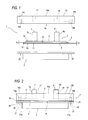
- Figure 1 is an exploded schematic front view of a first embodiment of a heat sink in accordance with the present invention;
- Figure 2 is a schematic front view of the heat sink of Figure 1;
- Figure 3 is a schematic top plan view of the heat sink of Figure 1;
- Figure 4 is a schematic bottom plan view of the heat sink of Figure 1;
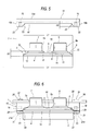
- Figure 5 is an exploded schematic front view of a second embodiment of a heat sink in accordance with the present invention;
- Figure 6 is a schematic front view of the heat sink of Figure 5 in a preferred application configuration;
- Figure 7 is a schematic top plan view of the heat sink of Figure 5;
- Figure 8 is a schematic bottom plan view of the heat sink of Figure 5;
- Figure 9 is an exploded schematic front view of a third embodiment of a heat sink in accordance with the present invention;
- Figure 10 is a schematic front view of the heat sink of Figure 9 in a preferred operating configuration;
- Figure 11 is a schematic top plan view of a fourth embodiment of a heat sink in accordance with the present invention;
- Figure 12 is a schematic front view of the heat sink of Figure 11;
- Figure 13 is a schematic side view of the heat sink of Figure 11;
- Figure 14 is a schematic top plan view of a fifth embodiment of a heat sink in accordance with the present invention;
- Figure 15 is a schematic bottom plan view, with some parts cut away for greater clarity, of the heat sink of Figure 14;
- Figure 16 is a schematic front view of the heat sink of Figure 14;
- Figure 17 is a schematic front view of a preferred application of a heat sink in accordance with the present invention.
- With reference to the accompanying drawings, the
numeral 1 denotes a fluid-cooled heat sink in accordance with the present invention. - The
heat sink 1 is preferably for disposing of heat in electronic components with power between around a hundred watts and several thousand watts. - The
heat sink 1 comprises a dissipation element orheat exchanger 2, which is put in contact with at least oneelectronic component 3 to be cooled. - As illustrated, the
electronic component 3 has aflange 3a with which it is connected to theheat exchanger 2 using methods described in more detail below. - The
heat exchanger 2 is affected by the flow of a coolant liquid which absorbs and carries away the heat exchanged between thecomponent 3 and thedissipation element 2, flowing in theheat exchanger 2. - The
heat exchanger 2 has a firstouter surface 4 for connection to thecomponent 3 and a secondouter surface 5, these surfaces enclosing achannel 6 for circulation of the cooling liquid. - The
channel 6 has aninlet 7 for the cooling fluid and anoutlet 8 for it. - In the solutions illustrated, the
inlet 7 and theoutlet 8 of thechannel 6 have arespective connector - The positions of the
inlet 7 and theoutlet 8 of thechannel 6 are illustrated by way of example and conventionally indicated as inlet and outlet. Similarly, the extension of thechannel 6 in theheat exchanger 2 has any preferred course. In alternative embodiments not illustrated the positions of theinlet 7 and theoutlet 8, depending on the extension of thecorresponding channel 6 for circulation of the cooling fluid, may be any according to the different construction requirements. - The
heat exchanger 2 preferably comprises afirst plate 9 with thickness T1 and width L1, having afirst face 10 and asecond face 11. - The
heat exchanger 2 also comprises asecond plate 12 with thickness T2 and width L2, having afirst face 13 and asecond face 14. - The
first plate 9 and thesecond plate 12 are joined together and in particular thefirst face 13 of thesecond plate 12 is jointed to thesecond face 11 of thefirst plate 9 to enclose thechannel 6 in which the cooling fluid flows. - As illustrated, the
second face 14 of thesecond plate 12 comprises theouter surface 4 for connection of theheat exchanger 1 to theelectronic component 3. - Moreover, the
channel 6 is preferably made in thefirst plate 9 by permanent setting it. - In practice, the coolant fluid flows in contact with the
second plate 12 and absorbs the latter's heat which by conduction propagates from theelectronic component 3 through the connectingsurface 4. - The first and
second plates - In particular, the
plates - The thickness T1 of the
plate 9 is preferably between several tenths of a millimetre and several millimetres to minimise the material used and optimise working. - The thickness T2 of the
plate 12 is preferably between several tenths of a millimetre and several millimetres to minimise the material used to produce the plate. - The reduced thicknesses T1 and T2 are such that, as described in more detail below, the
dissipation element 2 has a structure which can be deformed by bending, able to adapt to theelectronic component 3 to be cooled. - In particular, in the preferred embodiment illustrated by way of example in Figures 1 and 2, the
plate 9 has a thickness T1 of around 1 mm. - Moreover, the
plate 12 preferably has a thickness T2 of around 1 mm. - The
heat sink 1 disclosed also comprises astiffening element 15 for associating theheat exchanger 2 with theelectronic component 3. - In particular, the
stiffening element 15 operates on theheat exchanger 2 at the secondouter surface 5 and, in particular, has aface 16 for connection to said secondouter surface 5. - Advantageously, the
stiffening element 15 has acentral portion 15a, substantially comprising the connectingface 16, designed to impact on theheat exchanger 2 to press it on theelectronic component 3. - The
stiffening element 15 also has, positioned on opposite sides of thecentral portion 15a,lateral portions 15b preferably designed to fix theelement 15 to theelectronic component 3, as described in more detail below. - The
stiffening element 15 is preferably made of plastic or a composite material or metal which can be moulded or stamped (for example die-cast or stamped plate). - The
element 15 has a stiff structure so that it gives theheat exchanger 2 in particular the mechanical properties necessary for assembly with theelectronic component 3. - The stiffening
element 15 is preferably made as a single body to optimise its production at industrial level. - As illustrated in Figures 1 to 4, the stiffening
element 15 affects the whole of thefirst face 10 of thefirst plate 9 which therefore forms the secondouter surface 5 for connection to theelement 15. - The
outer surface 5 is substantially flat and, similarly, theface 16 for connecting the stiffeningelement 15 to theheat exchanger 2 is also substantially flat. - The stiffening
element 15 has a first and asecond opening inlet 7 and theoutlet 8 of thechannel 6 for circulation of the cooling fluid. - In particular, the
openings - The stiffening
element 15 has engagement means 19 for themeans 21 for fixing thecomponent 3 to theelement 15, preferably using theflange 3a. - The engagement means 19 are preferably positioned at the
lateral portions 15b of the stiffeningelement 15. - In the embodiments illustrated by way of example, the engagement means 19 consist of a plurality of
holes 19, preferably dead holes, with a thread in which the fixing means 21 consisting for example ofscrews 21a engage. - Figures 1 and 2 show how the engagement means 19 preferably comprise threaded
bushings 19a inserted in thestiffening element 15. - Engaging in the
holes 19 or in thebushings 19a throughholes 20 made in theflange 3a, thescrews 21a pull thestiffening element 15 towards theelectronic component 3 so that thedissipation element 2, between the stiffeningelement 15, in particular thecentral portion 15a, and thecomponent 3, effectively adheres to the latter, optimising the heat exchange for component cooling. - In this way, when the
heat sink 1 is assembled, theheat exchanger 2 is locked on theelectronic component 3 by the stiffeningelement 15 which presses theheat exchanger 2 under the action of the fixing means 21. - The stiffening
element 15 gives theheat exchanger 2 enough stiffness for assembly and theface 14 of thesecond plate 12 is firmly in contact with theelectronic component 3, since theheat exchanger 2 is forced onto thecomponent 3 by the stiffeningelement 15. - In practice, the stiffening
element 15 is a stiffening element for theheat exchanger 2 to give the latter mechanical properties suitable forheat sink 1 assembly on theelectronic component 3. - It should be noticed, as illustrated in Figures 2, 6, 10, 12 and 16, that, in a
heat sink 1 assembly configuration on theelectronic component 3, between thelateral portions 15b of the stiffeningelement 15 and theflange 3a of theelectronic component 3 there is preferably agap 29. - In other words, the maximum height H1 of the
heat exchanger 2 is greater than the distance H2 between theface 16 of theassembly element 15, substantially in contact with thefirst face 10 of thefirst plate 9, and thesurfaces 33 of thelateral portions 3b of the stiffeningelement 15 opposite theflange 3a. - With reference to Figure 16, the maximum height H1 of the
heat exchanger 2 is greater than the distance H2 between theface 16 of theassembly element 15 substantially in contact with thefirst face 10 of thefirst plate 9 and thesurfaces 33 of thelateral portions 3b of the stiffeningelement 15 opposite thefirst face 13 of thesecond plate 12 which is facing thefirst plate 9. - The
gap 29 is such that by acting on the fixing means 21 it is possible to obtain optimum pressure of thecentral portion 15a of the stiffeningelement 15 on theheat exchanger 2, thus optimising the adhesion of theheat exchanger 2 on theelectronic component 3 and the heat exchange between the two. - In particular Figure 17 illustrates a
preferred heat sink 1 application. - It should be noticed that the
gap 29 is such that it allows, through the action of the fixing means 21, suitable bending, schematically indicated with the arrows F, of theheat exchanger 2 and theelectronic component 3flange 3a, producing greater adhesion between the two, in particular at acentral zone 3b of theelectronic component 3 where more heat is usually produced. - It should be noticed that, as illustrated in Figures 3, 6, 7, 11 and 14, the stiffening
element 15 comprises second engagement means 26 for fixingmeans 27. - In particular, the second engagement means 26 allow the
heat sink 1 to be assembled to astructure 28, which is not part of the present invention and therefore is not described in detail, which supports theelectronic components 3 by means of the stiffeningelement 15. - These second engagement means 26 for
means 27 for fixing the stiffeningelement 15 to asupport structure 28 are preferably in thestiffening element 15 itself, on the opposite side to the second engagement means 19 for themeans 21 for fixing thecomponent 3 to theelement 15. - In the solution illustrated in Figures 5 and 6, the connecting
face 16 of the stiffeningelement 15, that is to say thecentral portion 15a, is close to thefirst face 10 of theplate 9. - In practice, for example, substantially
curved portions 22 of theplate 9 correspond to substantiallystraight portions 23 of the stiffeningelement 15 connectingface 16. - In this way, the pressure applied by the stiffening
element 15 on theheat exchanger 2 is distributed on theouter surface 5. In particular, by appropriately shaping the stiffeningelement 15, the load on theheat exchanger 2 can be appropriately concentrated according to requirements, in a way not described in further detail. - In particular with reference to Figures 9 and 10 it should be noticed that the connecting
face 16 is shaped to match thefirst face 10 of theplate 9. Substantiallycurved portions 22 of theplate 9 correspond to substantiallycurved portions 24 of the connectingface 16, substantially following the same course as theportions 22. - In this way, the pressure applied by the stiffening
element 15 against theheat exchanger 2 is better distributed on the portion of thefirst face 10 of theheat exchanger 2 affected by the stiffeningelement 15. - In particular with reference to Figures 7 and 11, it should be noticed that in the preferred embodiments illustrated the
outer surface 5 of theheat exchanger 2 affected by the stiffeningelement 15 consists of a portion of theface 10 of thefirst plate 9. - As illustrated in Figures 14, 15 and 16, the width L2 of the
plate 12 is greater than the width L1 of theplate 9. - In this way, an
outer perimeter portion 12a is defined on theplate 12, internally delimited by theplate 9. - In this
perimeter portion 12a, that is to say, the part of theplate 12 not connected to theplate 9, there are third engagement means for themeans 21 for fixing theelectronic component 3 to thestiffening element 15. - In particular, in the
perimeter portion 12a there areholes 30 for the passage of thescrews 21a. - In this way, the
electronic component 3flange 3a, and therefore theelectronic component 3 itself, thedissipation element 2 and thestiffening element 15, are positioned relative to one another, making assembly of the components particularly easy. - It should also be noticed that the
plate 9 is joined on theplat e 12 substantially at theperimeter portion 12a. - Said join preferably being made, as already indicated, with metalwork processes involving weld material, the
perimeter portion 12a is such that, during the joining of the twoplates face 14 of theplate 12 which therefore retains unchanged its surface properties such as roughness, not requiring further treatments which could compromise its thermal efficiency and mechanical strength. - In particular with reference to Figures 11, 12, 16 and 17, it should be noticed that the
heat sink 1 comprises structural stiffening means 25 positioned in thechannel 6. - Said means 25 prevent the
channel 6 from being crushed under the pressure applied by the stiffeningelement 15, although keep the thicknesses T1 and T2 of theplates - Advantageously, the structural stiffening means 25 substantially occupy the entire height of the
channel 6. - The
heat sink 1 also comprises means 31 for generating a turbulence in the cooling fluid which flows in thechannel 6 duringheat sink 1 operation. - The structural stiffening means 25 and the
means 31 for generating a turbulence consist of a so-called "fret" 32 inserted in thechannel 6. - The fret 32, otherwise know as a "turbulator" allows the
heat exchanger 2 to resist the pressure from the stiffeningelement 15 and generates turbulence in the fluid passing through it. The fret 32 is preferably of the staggered type. - As illustrated in Figure 17, the fret is preferably of the undulated type.
- In this way it is possible to keep the thicknesses T1 and T2 of the
plates electronic component 3 thanks to themeans 31 for generating a turbulence. - The invention described brings important advantages. The use of thin plates, thanks to the presence of the stiffening element which performs structural functions, allows a significant reduction in the quantity of material used, thus reducing the weight and costs of the heat sink. The mechanical properties necessary for correct assembly of the heat sink on the electronic component are required, as indicated, of the stiffening element which, preferably being made of plastic, is economical and easy to work.
- The stiffening element shaped to match the heat exchanger allows it to be pressed against the electronic component, guaranteeing effective heat exchange. The thinness of the heat exchanger allows it a minimum deformability by bending, which guarantees optimum adhesion on the electronic component to be cooled.
- The appropriately shaped stiffening element also allows the forces and tensions due to the fixing means to be distributed in the most suitable zones of the electronic component, for example at the centre.
- The invention described has evident industrial applications and may be modified and adapted in several ways without thereby departing from the scope of the inventive concept. Moreover, all details of the invention may be substituted by technically equivalent elements.
Claims (22)
- A fluid-cooled heat sink, comprising:a heat exchanger (2) which can be associated with at least one electronic component (3), the heat exchanger (2) having a first outer surface (4) for contact with the electronic component (3) and a second outer surface (5), and having at least one channel (6) with an inlet (7) and an outlet (8) for a cooling fluid, the heat sink being characterised in that it comprises a stiffening element (15) associated with the heat exchanger (2) for applying the heat exchanger (2) to the electronic component (3) and pressing the heat exchanger (2) against the electronic component.
- The heat sink according to claim 1, characterised in that the stiffening element (15) is connected to the heat exchanger (2) substantially at the second outer surface (5).
- The heat sink according to claim 2, characterised in that the stiffening element (15) at least partly affects the outer connecting surface (5).
- The heat sink according to any of the claims from 1 to 3, characterised in that the stiffening element (15) has a face (16) for connection to the heat exchanger (2) substantially at the second outer surface (5).
- The heat sink according to claim 4, characterised in that the connecting face (16) is substantially flat.
- The heat sink according to claim 4, characterised in that the stiffening element (15) connecting face (16) is shaped to match the outer fixing surface (5).
- The heat sink according to any of the claims from 1 to 6, characterised in that the heat exchanger (2) is deformable, in particular when assembled on the respective electronic component (3).
- The heat sink according to any of the claims from 1 to 7, characterised in that the stiffening element (15) comprises engagement means (19) for means (21) for fixing the electronic component (3) to the stiffening element (15), the heat exchanger (2) being positioned and held between the electronic component (3) and the stiffening element (15).
- The heat sink according to any of the claims from 1 to 8, characterised in that the heat exchanger (2) comprises a first plate (9) which has a first face (10) and a second face (11);
a second plate (12) which has a first face (13) and a second face (14), the first face (13) of the second plate (12) being joined to the second face (11) of the first plate (9), the channel (6) being between the first face (13) of the second plate (12) and the second face (11) of the first plate (9), the second face (14) of the second plate (12) at least partly forming the first outer surface (4) for contact with the electronic component (3), the first face (10) of the first plate (9) at least partly forming the second outer surface (5). - The heat sink according to claim 9, characterised in that the channel (6) is made in the second face (11) of the first plate (9).
- The heat sink according to claim 9 or 10, characterised in that the width (L2) of the second plate (12) is substantially greater than the width (L1) of the first plate (9).
- The heat sink according to any of the claims from 9 to 11, characterised in that the thickness (T1) of the first plate (9) is between several tenths of a millimetre and several millimetres.
- The heat sink according to any of the claims from 9 to 12, characterised in that the thickness (T2) of the second plate (9) is between several tenths of a millimetre and several millimetres.
- The heat sink according to any of the claims from 1 to 13, characterised in that it comprises heat exchanger (2) structural stiffening means (25) positioned in the channel (6).
- The heat sink according to claim 14, characterised in that the heat exchanger (2) structural stiffening means (25) comprise turbulators (32) positioned in the channel (6).
- The heat sink according to any of the claims from 1 to 15, characterised in that it comprises means (31) for generating a turbulence in the cooling fluid, said means being positioned in the channel (6) .
- The heat sink according to claim 16, characterised in that the means (31) for generating a turbulence comprise turbulators (32) positioned in the channel (6).
- The heat sink according to any of the claims from 1 to 17, characterised in that the stiffening element (15) is made of plastic.
- The heat sink according to any of the claims from 1 to 18, characterised in that the stiffening element (15) is made of a composite material.
- The heat sink according to any of the claims from 1 to 19, characterised in that the stiffening element (15) is made of a material which can be moulded or stamped.
- The heat sink according to any of the claims from 1 to 20, characterised in that the stiffening element (15) is stiff.
- The heat sink according to any of the claims from 1 to 21, characterised in that the stiffening element (15) is made as a single body.
Priority Applications (4)
| Application Number | Priority Date | Filing Date | Title |
|---|---|---|---|
| EP06425774.4A EP1921676B1 (en) | 2006-11-13 | 2006-11-13 | Heat sink |
| PCT/US2007/023051 WO2008063372A2 (en) | 2006-11-13 | 2007-11-01 | Heat sink |
| US12/514,176 US8616267B2 (en) | 2006-11-13 | 2007-11-01 | Heat sink |
| TW096141882A TW200839981A (en) | 2006-11-13 | 2007-11-06 | Heat sink |
Applications Claiming Priority (1)
| Application Number | Priority Date | Filing Date | Title |
|---|---|---|---|
| EP06425774.4A EP1921676B1 (en) | 2006-11-13 | 2006-11-13 | Heat sink |
Publications (2)
| Publication Number | Publication Date |
|---|---|
| EP1921676A1 true EP1921676A1 (en) | 2008-05-14 |
| EP1921676B1 EP1921676B1 (en) | 2019-03-06 |
Family
ID=37876012
Family Applications (1)
| Application Number | Title | Priority Date | Filing Date |
|---|---|---|---|
| EP06425774.4A Active EP1921676B1 (en) | 2006-11-13 | 2006-11-13 | Heat sink |
Country Status (4)
| Country | Link |
|---|---|
| US (1) | US8616267B2 (en) |
| EP (1) | EP1921676B1 (en) |
| TW (1) | TW200839981A (en) |
| WO (1) | WO2008063372A2 (en) |
Cited By (1)
| Publication number | Priority date | Publication date | Assignee | Title |
|---|---|---|---|---|
| DE102023206169A1 (en) * | 2023-06-28 | 2025-01-02 | Vitesco Technologies GmbH | high-voltage box for an electrically powered vehicle |
Families Citing this family (10)
| Publication number | Priority date | Publication date | Assignee | Title |
|---|---|---|---|---|
| US9401317B2 (en) | 2011-01-26 | 2016-07-26 | Aavid Thermalloy, Llc | Heat sink mount and assembly |
| WO2013159172A1 (en) | 2012-04-26 | 2013-10-31 | Dana Canada Corporation | Heat exchanger with adapter module |
| CN107851867B (en) * | 2015-08-05 | 2020-09-29 | 日轻热交株式会社 | cooler |
| US9980415B2 (en) | 2015-08-20 | 2018-05-22 | Toyota Motor Engineering & Manufacturing North America, Inc. | Configurable double-sided modular jet impingement assemblies for electronics cooling |
| US20190301809A1 (en) | 2018-04-03 | 2019-10-03 | Aavid Thermalloy, Llc | Wrap around heat exchanger |
| DE102020203892A1 (en) | 2019-03-29 | 2020-10-01 | Dana Canada Corporation | EXCHANGER MODULE WITH AN ADAPTER MODULE FOR DIRECT MOUNTING ON A VEHICLE COMPONENT |
| JP7487533B2 (en) * | 2020-04-02 | 2024-05-21 | 富士電機株式会社 | Semiconductor modules and vehicles |
| US12495515B2 (en) * | 2022-03-04 | 2025-12-09 | Aavid Thermalloy, Llc | Liquid cooled heat exchanger |
| CA3249206A1 (en) | 2022-04-28 | 2023-11-02 | Tyco Fire & Security Gmbh | Direct evaporative cooling system for data center with fan and water optimization |
| US12302530B2 (en) * | 2022-06-03 | 2025-05-13 | Aavid Thermalloy, Llc | Method and apparatus for immersion boiler support |
Citations (7)
| Publication number | Priority date | Publication date | Assignee | Title |
|---|---|---|---|---|
| JPH07130925A (en) * | 1993-11-02 | 1995-05-19 | Mitsubishi Electric Corp | Semiconductor device and manufacturing method thereof |
| US20020162673A1 (en) * | 2001-05-03 | 2002-11-07 | Cook Derrick E. | Use of doped synthetic polymer materials for packaging of power electric assemblies for a liquid cooled module |
| FR2826831A1 (en) * | 2001-06-29 | 2003-01-03 | Peugeot Citroen Automobiles Sa | Car electronics power module cooling mechanism having enclosure with side walls/sole plate base around electronics module providing cooling enclosure with input/output fluid ports. |
| WO2003095922A2 (en) * | 2002-05-08 | 2003-11-20 | Danfoss Silicon Power Gmbh | Cooling unit and flow distributing element for use in such unit |
| US20050011635A1 (en) * | 2003-07-15 | 2005-01-20 | Industrial Technology Research Institute | Cold plate with vortex generator |
| US20060050483A1 (en) * | 2004-09-08 | 2006-03-09 | Wilson Michael J | Liquid cooled heat sink with cold plate retention mechanism |
| DE102005012501A1 (en) * | 2005-03-16 | 2006-09-21 | Behr Industry Gmbh & Co. Kg | Device for cooling electronic components |
Family Cites Families (8)
| Publication number | Priority date | Publication date | Assignee | Title |
|---|---|---|---|---|
| US4612978A (en) * | 1983-07-14 | 1986-09-23 | Cutchaw John M | Apparatus for cooling high-density integrated circuit packages |
| US6301097B1 (en) * | 1999-07-27 | 2001-10-09 | International Business Machines Corporation | Inflatable sealing system for low temperature electronic module |
| JP2001053205A (en) | 1999-08-05 | 2001-02-23 | Hitachi Ltd | Multi-chip module sealing cooling device |
| US6125036A (en) * | 1999-10-12 | 2000-09-26 | International Business Machines Corporation | Moisture barrier seals for cooled IC chip module assemblies |
| TW591363B (en) * | 2001-10-10 | 2004-06-11 | Aavid Thermalloy Llc | Heat collector with mounting plate |
| DE10207873A1 (en) | 2002-02-23 | 2003-09-04 | Modine Mfg Co | Cooling device for electronic or electrical components in motor vehicle, has container adjoining cooling fluid flow channel for receiving heat lost from components |
| US6665187B1 (en) * | 2002-07-16 | 2003-12-16 | International Business Machines Corporation | Thermally enhanced lid for multichip modules |
| US7272006B2 (en) * | 2005-09-30 | 2007-09-18 | Intel Corporation | IC coolant microchannel assembly with integrated attachment hardware |
-
2006
- 2006-11-13 EP EP06425774.4A patent/EP1921676B1/en active Active
-
2007
- 2007-11-01 WO PCT/US2007/023051 patent/WO2008063372A2/en not_active Ceased
- 2007-11-01 US US12/514,176 patent/US8616267B2/en active Active
- 2007-11-06 TW TW096141882A patent/TW200839981A/en unknown
Patent Citations (7)
| Publication number | Priority date | Publication date | Assignee | Title |
|---|---|---|---|---|
| JPH07130925A (en) * | 1993-11-02 | 1995-05-19 | Mitsubishi Electric Corp | Semiconductor device and manufacturing method thereof |
| US20020162673A1 (en) * | 2001-05-03 | 2002-11-07 | Cook Derrick E. | Use of doped synthetic polymer materials for packaging of power electric assemblies for a liquid cooled module |
| FR2826831A1 (en) * | 2001-06-29 | 2003-01-03 | Peugeot Citroen Automobiles Sa | Car electronics power module cooling mechanism having enclosure with side walls/sole plate base around electronics module providing cooling enclosure with input/output fluid ports. |
| WO2003095922A2 (en) * | 2002-05-08 | 2003-11-20 | Danfoss Silicon Power Gmbh | Cooling unit and flow distributing element for use in such unit |
| US20050011635A1 (en) * | 2003-07-15 | 2005-01-20 | Industrial Technology Research Institute | Cold plate with vortex generator |
| US20060050483A1 (en) * | 2004-09-08 | 2006-03-09 | Wilson Michael J | Liquid cooled heat sink with cold plate retention mechanism |
| DE102005012501A1 (en) * | 2005-03-16 | 2006-09-21 | Behr Industry Gmbh & Co. Kg | Device for cooling electronic components |
Cited By (2)
| Publication number | Priority date | Publication date | Assignee | Title |
|---|---|---|---|---|
| DE102023206169A1 (en) * | 2023-06-28 | 2025-01-02 | Vitesco Technologies GmbH | high-voltage box for an electrically powered vehicle |
| DE102023206169B4 (en) | 2023-06-28 | 2025-02-27 | Vitesco Technologies GmbH | high-voltage box for an electrically powered vehicle |
Also Published As
| Publication number | Publication date |
|---|---|
| TW200839981A (en) | 2008-10-01 |
| WO2008063372A2 (en) | 2008-05-29 |
| EP1921676B1 (en) | 2019-03-06 |
| WO2008063372B1 (en) | 2008-12-04 |
| WO2008063372A8 (en) | 2013-10-24 |
| US20100044015A1 (en) | 2010-02-25 |
| US8616267B2 (en) | 2013-12-31 |
| WO2008063372A3 (en) | 2008-09-25 |
Similar Documents
| Publication | Publication Date | Title |
|---|---|---|
| US8616267B2 (en) | Heat sink | |
| CN106455456B (en) | A copper-aluminum composite water-cooling plate and its processing and manufacturing method, and a water-cooling heat dissipation method | |
| CN215418156U (en) | Microchannel copper-aluminum composite relieving liquid cooling radiator | |
| CN118055591A (en) | Electronic component and electronic equipment | |
| CN206657307U (en) | Board-like water cooling graphic card radiator | |
| US12042890B2 (en) | Method for manufacturing a heat sink | |
| US8490681B2 (en) | Fluid cooling system | |
| JP3010080U (en) | Electronic component cooler | |
| CN222424564U (en) | Radiator and humidifier | |
| CN111132530A (en) | A kind of electrical quick-installation cooling device and manufacturing method | |
| CN120512879A (en) | Composite heat dissipation module and composite heat dissipation system | |
| CN111059924A (en) | Double-sided elliptical streaming water-cooling radiator | |
| JP3010602U (en) | Electronic component cooler | |
| CN101553704A (en) | heat sink | |
| EP4282234B1 (en) | A method for cooling heat generating power electronics and a cooling device | |
| CN213421920U (en) | Different material laminated plate heat exchanger | |
| CN223978927U (en) | Liquid cooling plate structure and domain controller | |
| CN112556454A (en) | Welding sheet metal shape heat conduction heat abstractor of preapring for an unfavorable turn of events | |
| CN219780772U (en) | Cooling device and water cooling system | |
| CN211321879U (en) | Reinforcing structure of heat dissipation module substrate | |
| CN221409645U (en) | Cold plate | |
| CN120751675B (en) | Microchannel domain controller and vehicle | |
| CN224139339U (en) | A controller housing for a miniature electric actuator | |
| CN221381432U (en) | Power module and electronic equipment | |
| CN223553631U (en) | High-reliability aerospace cold plate joint |
Legal Events
| Date | Code | Title | Description |
|---|---|---|---|
| PUAI | Public reference made under article 153(3) epc to a published international application that has entered the european phase |
Free format text: ORIGINAL CODE: 0009012 |
|
| AK | Designated contracting states |
Kind code of ref document: A1 Designated state(s): AT BE BG CH CY CZ DE DK EE ES FI FR GB GR HU IE IS IT LI LT LU LV MC NL PL PT RO SE SI SK TR |
|
| AX | Request for extension of the european patent |
Extension state: AL BA HR MK RS |
|
| 17P | Request for examination filed |
Effective date: 20081113 |
|
| AKX | Designation fees paid |
Designated state(s): AT BE BG CH CY CZ DE DK EE ES FI FR GB GR HU IE IS IT LI LT LU LV MC NL PL PT RO SE SI SK TR |
|
| 17Q | First examination report despatched |
Effective date: 20090605 |
|
| GRAP | Despatch of communication of intention to grant a patent |
Free format text: ORIGINAL CODE: EPIDOSNIGR1 |
|
| STAA | Information on the status of an ep patent application or granted ep patent |
Free format text: STATUS: GRANT OF PATENT IS INTENDED |
|
| INTG | Intention to grant announced |
Effective date: 20180705 |
|
| GRAS | Grant fee paid |
Free format text: ORIGINAL CODE: EPIDOSNIGR3 |
|
| GRAA | (expected) grant |
Free format text: ORIGINAL CODE: 0009210 |
|
| STAA | Information on the status of an ep patent application or granted ep patent |
Free format text: STATUS: THE PATENT HAS BEEN GRANTED |
|
| AK | Designated contracting states |
Kind code of ref document: B1 Designated state(s): AT BE BG CH CY CZ DE DK EE ES FI FR GB GR HU IE IS IT LI LT LU LV MC NL PL PT RO SE SI SK TR |
|
| REG | Reference to a national code |
Ref country code: GB Ref legal event code: FG4D |
|
| REG | Reference to a national code |
Ref country code: CH Ref legal event code: EP Ref country code: AT Ref legal event code: REF Ref document number: 1105695 Country of ref document: AT Kind code of ref document: T Effective date: 20190315 |
|
| REG | Reference to a national code |
Ref country code: DE Ref legal event code: R096 Ref document number: 602006057544 Country of ref document: DE |
|
| REG | Reference to a national code |
Ref country code: IE Ref legal event code: FG4D |
|
| REG | Reference to a national code |
Ref country code: NL Ref legal event code: MP Effective date: 20190306 |
|
| REG | Reference to a national code |
Ref country code: LT Ref legal event code: MG4D |
|
| PG25 | Lapsed in a contracting state [announced via postgrant information from national office to epo] |
Ref country code: FI Free format text: LAPSE BECAUSE OF FAILURE TO SUBMIT A TRANSLATION OF THE DESCRIPTION OR TO PAY THE FEE WITHIN THE PRESCRIBED TIME-LIMIT Effective date: 20190306 Ref country code: LT Free format text: LAPSE BECAUSE OF FAILURE TO SUBMIT A TRANSLATION OF THE DESCRIPTION OR TO PAY THE FEE WITHIN THE PRESCRIBED TIME-LIMIT Effective date: 20190306 Ref country code: SE Free format text: LAPSE BECAUSE OF FAILURE TO SUBMIT A TRANSLATION OF THE DESCRIPTION OR TO PAY THE FEE WITHIN THE PRESCRIBED TIME-LIMIT Effective date: 20190306 |
|
| PG25 | Lapsed in a contracting state [announced via postgrant information from national office to epo] |
Ref country code: BG Free format text: LAPSE BECAUSE OF FAILURE TO SUBMIT A TRANSLATION OF THE DESCRIPTION OR TO PAY THE FEE WITHIN THE PRESCRIBED TIME-LIMIT Effective date: 20190606 Ref country code: GR Free format text: LAPSE BECAUSE OF FAILURE TO SUBMIT A TRANSLATION OF THE DESCRIPTION OR TO PAY THE FEE WITHIN THE PRESCRIBED TIME-LIMIT Effective date: 20190607 Ref country code: LV Free format text: LAPSE BECAUSE OF FAILURE TO SUBMIT A TRANSLATION OF THE DESCRIPTION OR TO PAY THE FEE WITHIN THE PRESCRIBED TIME-LIMIT Effective date: 20190306 Ref country code: NL Free format text: LAPSE BECAUSE OF FAILURE TO SUBMIT A TRANSLATION OF THE DESCRIPTION OR TO PAY THE FEE WITHIN THE PRESCRIBED TIME-LIMIT Effective date: 20190306 |
|
| REG | Reference to a national code |
Ref country code: AT Ref legal event code: MK05 Ref document number: 1105695 Country of ref document: AT Kind code of ref document: T Effective date: 20190306 |
|
| PG25 | Lapsed in a contracting state [announced via postgrant information from national office to epo] |
Ref country code: IT Free format text: LAPSE BECAUSE OF FAILURE TO SUBMIT A TRANSLATION OF THE DESCRIPTION OR TO PAY THE FEE WITHIN THE PRESCRIBED TIME-LIMIT Effective date: 20190306 Ref country code: RO Free format text: LAPSE BECAUSE OF FAILURE TO SUBMIT A TRANSLATION OF THE DESCRIPTION OR TO PAY THE FEE WITHIN THE PRESCRIBED TIME-LIMIT Effective date: 20190306 Ref country code: CZ Free format text: LAPSE BECAUSE OF FAILURE TO SUBMIT A TRANSLATION OF THE DESCRIPTION OR TO PAY THE FEE WITHIN THE PRESCRIBED TIME-LIMIT Effective date: 20190306 Ref country code: SK Free format text: LAPSE BECAUSE OF FAILURE TO SUBMIT A TRANSLATION OF THE DESCRIPTION OR TO PAY THE FEE WITHIN THE PRESCRIBED TIME-LIMIT Effective date: 20190306 Ref country code: ES Free format text: LAPSE BECAUSE OF FAILURE TO SUBMIT A TRANSLATION OF THE DESCRIPTION OR TO PAY THE FEE WITHIN THE PRESCRIBED TIME-LIMIT Effective date: 20190306 Ref country code: PT Free format text: LAPSE BECAUSE OF FAILURE TO SUBMIT A TRANSLATION OF THE DESCRIPTION OR TO PAY THE FEE WITHIN THE PRESCRIBED TIME-LIMIT Effective date: 20190706 Ref country code: EE Free format text: LAPSE BECAUSE OF FAILURE TO SUBMIT A TRANSLATION OF THE DESCRIPTION OR TO PAY THE FEE WITHIN THE PRESCRIBED TIME-LIMIT Effective date: 20190306 |
|
| PG25 | Lapsed in a contracting state [announced via postgrant information from national office to epo] |
Ref country code: PL Free format text: LAPSE BECAUSE OF FAILURE TO SUBMIT A TRANSLATION OF THE DESCRIPTION OR TO PAY THE FEE WITHIN THE PRESCRIBED TIME-LIMIT Effective date: 20190306 |
|
| REG | Reference to a national code |
Ref country code: DE Ref legal event code: R097 Ref document number: 602006057544 Country of ref document: DE |
|
| PG25 | Lapsed in a contracting state [announced via postgrant information from national office to epo] |
Ref country code: IS Free format text: LAPSE BECAUSE OF FAILURE TO SUBMIT A TRANSLATION OF THE DESCRIPTION OR TO PAY THE FEE WITHIN THE PRESCRIBED TIME-LIMIT Effective date: 20190706 Ref country code: AT Free format text: LAPSE BECAUSE OF FAILURE TO SUBMIT A TRANSLATION OF THE DESCRIPTION OR TO PAY THE FEE WITHIN THE PRESCRIBED TIME-LIMIT Effective date: 20190306 |
|
| PLBE | No opposition filed within time limit |
Free format text: ORIGINAL CODE: 0009261 |
|
| STAA | Information on the status of an ep patent application or granted ep patent |
Free format text: STATUS: NO OPPOSITION FILED WITHIN TIME LIMIT |
|
| PG25 | Lapsed in a contracting state [announced via postgrant information from national office to epo] |
Ref country code: DK Free format text: LAPSE BECAUSE OF FAILURE TO SUBMIT A TRANSLATION OF THE DESCRIPTION OR TO PAY THE FEE WITHIN THE PRESCRIBED TIME-LIMIT Effective date: 20190306 |
|
| 26N | No opposition filed |
Effective date: 20191209 |
|
| PG25 | Lapsed in a contracting state [announced via postgrant information from national office to epo] |
Ref country code: SI Free format text: LAPSE BECAUSE OF FAILURE TO SUBMIT A TRANSLATION OF THE DESCRIPTION OR TO PAY THE FEE WITHIN THE PRESCRIBED TIME-LIMIT Effective date: 20190306 |
|
| PG25 | Lapsed in a contracting state [announced via postgrant information from national office to epo] |
Ref country code: TR Free format text: LAPSE BECAUSE OF FAILURE TO SUBMIT A TRANSLATION OF THE DESCRIPTION OR TO PAY THE FEE WITHIN THE PRESCRIBED TIME-LIMIT Effective date: 20190306 |
|
| PGFP | Annual fee paid to national office [announced via postgrant information from national office to epo] |
Ref country code: GB Payment date: 20191127 Year of fee payment: 14 |
|
| REG | Reference to a national code |
Ref country code: CH Ref legal event code: PL |
|
| PG25 | Lapsed in a contracting state [announced via postgrant information from national office to epo] |
Ref country code: LU Free format text: LAPSE BECAUSE OF NON-PAYMENT OF DUE FEES Effective date: 20191113 Ref country code: LI Free format text: LAPSE BECAUSE OF NON-PAYMENT OF DUE FEES Effective date: 20191130 Ref country code: MC Free format text: LAPSE BECAUSE OF FAILURE TO SUBMIT A TRANSLATION OF THE DESCRIPTION OR TO PAY THE FEE WITHIN THE PRESCRIBED TIME-LIMIT Effective date: 20190306 Ref country code: CH Free format text: LAPSE BECAUSE OF NON-PAYMENT OF DUE FEES Effective date: 20191130 |
|
| REG | Reference to a national code |
Ref country code: BE Ref legal event code: MM Effective date: 20191130 |
|
| PG25 | Lapsed in a contracting state [announced via postgrant information from national office to epo] |
Ref country code: IE Free format text: LAPSE BECAUSE OF NON-PAYMENT OF DUE FEES Effective date: 20191113 |
|
| PG25 | Lapsed in a contracting state [announced via postgrant information from national office to epo] |
Ref country code: BE Free format text: LAPSE BECAUSE OF NON-PAYMENT OF DUE FEES Effective date: 20191130 |
|
| PG25 | Lapsed in a contracting state [announced via postgrant information from national office to epo] |
Ref country code: CY Free format text: LAPSE BECAUSE OF FAILURE TO SUBMIT A TRANSLATION OF THE DESCRIPTION OR TO PAY THE FEE WITHIN THE PRESCRIBED TIME-LIMIT Effective date: 20190306 |
|
| GBPC | Gb: european patent ceased through non-payment of renewal fee |
Effective date: 20201113 |
|
| PG25 | Lapsed in a contracting state [announced via postgrant information from national office to epo] |
Ref country code: FR Free format text: LAPSE BECAUSE OF NON-PAYMENT OF DUE FEES Effective date: 20191202 Ref country code: HU Free format text: LAPSE BECAUSE OF FAILURE TO SUBMIT A TRANSLATION OF THE DESCRIPTION OR TO PAY THE FEE WITHIN THE PRESCRIBED TIME-LIMIT; INVALID AB INITIO Effective date: 20061113 |
|
| PG25 | Lapsed in a contracting state [announced via postgrant information from national office to epo] |
Ref country code: GB Free format text: LAPSE BECAUSE OF NON-PAYMENT OF DUE FEES Effective date: 20201113 |
|
| P01 | Opt-out of the competence of the unified patent court (upc) registered |
Effective date: 20230526 |
|
| REG | Reference to a national code |
Ref country code: DE Ref legal event code: R079 Ref document number: 602006057544 Country of ref document: DE Free format text: PREVIOUS MAIN CLASS: H01L0023473000 Ipc: H10W0040470000 |
|
| PGFP | Annual fee paid to national office [announced via postgrant information from national office to epo] |
Ref country code: DE Payment date: 20251119 Year of fee payment: 20 |