EP1921442A1 - Verfahren und Anlage zur Qualitätskontrolle von Teilen - Google Patents
Verfahren und Anlage zur Qualitätskontrolle von Teilen Download PDFInfo
- Publication number
- EP1921442A1 EP1921442A1 EP07301450A EP07301450A EP1921442A1 EP 1921442 A1 EP1921442 A1 EP 1921442A1 EP 07301450 A EP07301450 A EP 07301450A EP 07301450 A EP07301450 A EP 07301450A EP 1921442 A1 EP1921442 A1 EP 1921442A1
- Authority
- EP
- European Patent Office
- Prior art keywords
- signal
- section
- signal segment
- polynomial
- sinor
- Prior art date
- Legal status (The legal status is an assumption and is not a legal conclusion. Google has not performed a legal analysis and makes no representation as to the accuracy of the status listed.)
- Withdrawn
Links
- 0 CCC(C)([C@@](CCNN)[C@](C)CC(C)(CI)*1CC1)N Chemical compound CCC(C)([C@@](CCNN)[C@](C)CC(C)(CI)*1CC1)N 0.000 description 1
Images


Classifications
-
- G—PHYSICS
- G01—MEASURING; TESTING
- G01B—MEASURING LENGTH, THICKNESS OR SIMILAR LINEAR DIMENSIONS; MEASURING ANGLES; MEASURING AREAS; MEASURING IRREGULARITIES OF SURFACES OR CONTOURS
- G01B11/00—Measuring arrangements characterised by the use of optical techniques
- G01B11/24—Measuring arrangements characterised by the use of optical techniques for measuring contours or curvatures
- G01B11/25—Measuring arrangements characterised by the use of optical techniques for measuring contours or curvatures by projecting a pattern, e.g. one or more lines, moiré fringes on the object
-
- G—PHYSICS
- G01—MEASURING; TESTING
- G01B—MEASURING LENGTH, THICKNESS OR SIMILAR LINEAR DIMENSIONS; MEASURING ANGLES; MEASURING AREAS; MEASURING IRREGULARITIES OF SURFACES OR CONTOURS
- G01B5/00—Measuring arrangements characterised by the use of mechanical techniques
- G01B5/0025—Measuring of vehicle parts
-
- G—PHYSICS
- G01—MEASURING; TESTING
- G01N—INVESTIGATING OR ANALYSING MATERIALS BY DETERMINING THEIR CHEMICAL OR PHYSICAL PROPERTIES
- G01N21/00—Investigating or analysing materials by the use of optical means, i.e. using sub-millimetre waves, infrared, visible or ultraviolet light
- G01N21/84—Systems specially adapted for particular applications
- G01N21/88—Investigating the presence of flaws or contamination
- G01N21/8851—Scan or image signal processing specially adapted therefor, e.g. for scan signal adjustment, for detecting different kinds of defects, for compensating for structures, markings, edges
Definitions
- the present invention relates to a method for controlling the quality of a part.
- the invention also relates to a quality control installation of parts, comprising at least one light source, at least one sensor and a computing unit connected to this sensor.
- the invention intends to remedy more particularly by proposing a method and a system for controlling the quality of parts that make it possible to detect both non-through and through defects that are adaptable to any type of device. rooms.
- the invention also relates to an information recording medium comprising instructions for the implementation of a control method as described above, when these instructions are executed by an electronic computing unit.
- the subject of the invention is a room quality control installation, comprising at least one light source, at least one sensor and an electronic computing unit capable of receiving data from this sensor, at least one light sources being equipped with an optical device capable of channeling the light projected onto the workpiece into a light line, this installation comprising an information recording medium as described above and the electronic computing unit being able to carry out the above instructions.
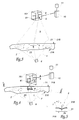
- the installation 1 shown in Figure 1 is designed to control the quality of stamped parts 2 to be mounted on motor vehicles.
- the installation 1 is provided directly at the outlet of the stamping line of the parts 2, the parts 2 being brought into the installation 1 by a conveyor 3 disposed at the outlet of the stamping press.
- the installation 1 comprises several robot 7 parts control 2, each programmed to control critical walls 21 of parts 2 may have defects. These critical walls 21 of the pieces 2 are identified prior to the quality control, by numerical simulation of the stamping operations on the pieces 2.
- the parts 2 are moved from one control robot 7 to another on a conveyor 5, designed to position each wall 21 to be controlled of a part 2 opposite a control device of the corresponding robot 7.
- the conveyor 5 is equipped with supports 51 intended to receive the parts 2 and to ensure their positioning in a reproducible manner.
- the transfer of the pieces 2 of the supply conveyor 3 to the control conveyor 5 is provided by a manipulator robot 4 capable of grasping parts 2 on the conveyor 3 and positioning them on the supports 51 of the conveyor 5.
- light sources 6 are situated below the conveyor 5, directly above each control robot 7.
- the conveyor 5 is designed to allow the transmission of a light beam F originating from the sources 6, so as to illuminate the lower face 21A of each wall 21 to be controlled by the corresponding robot 7.
- the beam F emitted by the sources 6 may be of any appropriate type, in particular a laser beam or a white light beam.
- Each control robot 7 comprises a base 71 on which is pivotally mounted an articulated arm 73.
- the arm 73 is provided with six degrees of freedom to guarantee a precise and reliable positioning of a control head 75 of the robot 7, fixed on the arm 73, with respect to the walls 21 to be controlled by this robot 7.
- Each robot 7 is programmed to control one or more critical walls 21 of parts 2 by bringing a control device 751 carried by the head 75 successively facing the different walls 21 to control.
- each robot 7 is programmed to move its control device 751 along a predetermined path, represented by the arrows T in FIG.
- the control device 751 comprises an optical camera 9 and a light source 8 associated with an optical device 81.
- the light source 8 emits any appropriate type of light, in particular a laser beam or white light.
- the optical device 81 is provided for channeling the light emitted by the light source 8 into a line of light L.
- the light source 8 and the camera 9 are positioned relative to each other so that the line of sight the source 8 and the line of sight of the camera 9 are intersecting, as shown in Figure 4.
- the angle ⁇ defined between the line of sight of the source 8 and the line of sight of the camera 9 is advantageously between about 10 ° and 170 °, preferably between about 45 ° and 135 °.
- the camera 9 is connected to a computing unit 10 of electronic or computer type, intended to process the data captured by the camera 9.
- a method for controlling the quality of a part 2 in the installation 1 firstly comprises a stage in which the piece 2 of the conveyor 3 for feeding the pieces to the control conveyor 5 is first transferred to the control conveyor 5.
- the part 2 is then moved by the conveyor 5 to a control zone of a first control robot 7, as shown by the arrow F 2 of FIG. 1.
- the conveyor 5 then immobilizes the part 2 and the first robot.
- control 7 moves its control device 751 according to the predefined trajectory T, in order to control each critical wall 21 of the part 2 supported by this first control robot 7.
- a method for controlling this wall 21 comprises two phases principal, a block diagram of each phase is shown in Figures 3 and 4.
- the light source 8 is inactivated.
- the camera 9 is used with a wide field of view to capture images of the upper face 21B of the wall 21 and thus detect the possible transmission, on the side of the upper face 21B, of light from the beam F emitted by the sources 6 disposed opposite the underside 21A.
- This first step allows the identification by backlight of through holes 23 possibly present on the wall 21.
- the camera 9 is positioned at a distance D of the order of 300 mm from the upper face 21B of the wall 21 controlled.
- control device 751 can be fixed or mobile relative to the wall 21 controlled, as the field of view of the camera 9 is sufficiently large or insufficient to cover the entire surface of the face 21B.
- the data captured by the camera 9 are processed by the calculation unit 10. It is thus possible not only to determine the position and the size of the through holes 23 present on the wall 21, but also, with the establishment of means suitable treatment, to qualify the appearance of these flaws.
- the light source 8 is activated, so as to project and move on the upper face 21B of the wall 21 a line of light L.
- the camera 9 is then used with a field reduced vision to capture images of the upper wall 21B.
- the camera 9 is designed to measure both the position of the light line L on the face 21B and the possible transmission on the side of this face 21B of light coming from the beam F coming from the lower sources 6.
- the camera 9 is positioned at a distance d of the order of 60 mm with respect to the upper face 21B of the wall 21 controlled.
- control device 751 is movable relative to the controlled wall 21, so as to move the light line L and to capture images of this line L over the entire surface of the upper face 21B of the wall 21 controlled, that is to say according to each section ⁇ of the wall 21.
- the data captured by the camera 9 are processed by the calculation unit 10.
- This second control phase can detect both outgoing defects 23 of the wall 21 controlled, with a resolution greater than that of the first control phase, and non-emerging defects 25 present on the upper face 21B of the wall 21 controlled.
- the number n of measurement points (x j , z j ) necessary for a reliable diagnosis of the quality of each section ⁇ of a wall 21 to be controlled is defined on the basis of a risk analysis.
- the risk analysis makes it possible to define an acceptable maximum height of defect, not entailing any significant change in the functionality and / or the lifetime of the part 2.
- a maximum height acceptable defect can be of the order of 0.01 mm.
- the camera 9 is then adapted to record a number n of measuring points (x j ; z j ) allowing the determination of a defect height to about 0.001 mm.
- the calculation unit 10 is designed to mathematically analyze the profile of the section ⁇ considered of the wall 21 from the n measurement points (x j ; z j ) transmitted by the camera 9.
- the calculation unit 10 is capable of detecting the presence of a defect opening or not opening on the section ⁇ , positioning this defect on the section ⁇ and, in the case of a non-emerging defect 25, or initiating failure, determining the height of the defect 25.
- the calculation unit 10 is programmed with a data processing algorithm of the camera 9, a block diagram of which is shown in FIGS. 6, 9 and 10. More specifically, the calculation unit 10 is performed from a conventional programmable computer capable of executing instructions recorded on an information recording medium 11.
- the support 11 includes instructions for executing the algorithm of FIGS. 6, 9 and 10 when the instructions are executed by the calculation unit 10.
- the algorithm used by the calculation unit 10 comprises several successive stages as described below.
- the intervals ( Ii ) 0 ⁇ i ⁇ N-1 are provided with a mutual overlap determined by a sliding pitch p, as shown in the example of FIG. 7.
- the number N of signal segments If (x) and the slip pitch p between two consecutive intervals I i are input data of the algorithm.
- Sinor (x) Normalization between 0 and 1 of Si (x).
- This filtering makes it possible to preserve a maximum of information contained in each signal segment. standardized Sinor (x), while taking into account measurement uncertainties.
- polynomial fit of order k ⁇ signal we mean a polynomial function of order k that best reproduces the experimental data of the signal, that is to say which is closer to the measuring points.
- the comparison of the two polynomial adjustment curves of different orders makes it possible to identify a possible defect on the interval I i of points of the section ⁇ corresponding to the filtered signal segment Spi (x). Indeed, if the two polynomial fit curves have significant differences, it means that the higher order polynomial fit identifies changes in the shape of the filtered signal segment Spi (x) undiagnosed by the polynomial fit of lower order. A defect is then present on the interval I i of points of the section ⁇ corresponding to the filtered signal segment Spi (x).
- the variation of the profile of the section ⁇ is relatively small, which makes it possible to limit the polynomial adjustment of each filtered signal segment Spi (x) to the order 2 to correctly describe the evolution of this signal segment .
- it is chosen to calculate the polynomial adjustment of order 4 of each filtered signal segment Spi (x), so as to compare the evolution of the curves of these two adjustments.
- the second and fourth order polynomial adjustments of each filtered signal segment Spi (x) thus serve as a reference for the detection of defects on the associated interval I i and, by iteration for all 0 i i N N - 1, allow the diagnosis of the quality of the section ⁇ of the wall 21 controlled.
- ⁇ di x d x ⁇ Sinor x - PO ⁇ 4 ⁇ i x d x .
- the defect leading to 23 is then positioned on the interval Ig of points of the section ⁇ corresponding to the signal segment Sg (x) for which the magnitude
- the product ⁇ i EROI * A i of the factors EROi and A i used for the diagnosis is calculated, and the signal segment Sg (x ) for which the product ⁇ g is the maximum of ( ⁇ i ) 0 i i ⁇ N -1 .
- the polynomial adjustments of order 2 and 4 are, in this step, carried out before normalization of the signal segment Sg (x) because the objective is to determine an actual height of defect.
- the height of the non-emerging defect located in the Ig interval of points of the section ⁇ is estimated as being the maximum of Q (x) greater than the average value Q moy of Q (x).
- the calculation unit 10 programmed with the calculation algorithm described previously allows the detection of non-emerging and outgoing defects 23 on each section ⁇ of the controlled wall 21, based on measurements made by the camera 9, and the quantization of non-emerging defects 25.
- the calculation unit 10 programmed with the calculation algorithm described previously allows the detection of non-emerging and outgoing defects 23 on each section ⁇ of the controlled wall 21, based on measurements made by the camera 9, and the quantization of non-emerging defects 25.
- the comparison criterion of the surface Ai with respect to the threshold S for the diagnosis of the quality of the section ⁇ on each interval I i , without use the criterion of comparison of the differences of the quadratic errors EROi .
- the criterion of comparison of the EROi makes it possible to validate the presence of a fault on an interval I i considered when A i is greater than S, and to detect a possible measurement error.
- the adaptive filtering step of each normalized signal segment Sinor (x) can be omitted.
- the normalization step of each signal segment Si (x) can be performed in a range other than [0, 1], the unique threshold S of defect detection then being different As a variant, this normalization step can also be omitted. The threshold S of fault detection must then be adapted for each signal segment Si (x).
- the segmentation step of the signal f (x) can be suppressed.
- the control device 751 fitted to each robot 7 of the installation 1 according to the invention makes it possible to control a large variety of defects potentially present on the walls 21 to be controlled in the room 2.
- the critical walls 21 of the part 2 are successively controlled by the control robots 7 of the installation 1, by repeating the first and second phases described above.
- the part 2 is directly discarded without resorting to the finer analysis of the second phase.
- the cycle time of the control is substantially reduced.
- each control robot 7 of the installation 1 ensures a great flexibility of the control installation and its adaptability to any type of parts, whatever their geometries and their dimensions.
- a change of the part to be controlled is realized in a simple way, by redefining the control trajectory T to be described by each control robot 7.
- the installation 1 according to the invention is easily integrable in the automotive industry because it does not require specific means, apart from the optical control device 751 and the calculation unit 10.
- the installation 1 is adapted to high production rates, thanks to the flexibility of the control robots 7 and the presence of the conveyors 3 and 5 and the manipulator robot 4.
- control device 751 can be arranged on a fixed foot, while the part 2 to be controlled is moved opposite the control device by a manipulator robot.
- the control device 751 may also comprise several cameras 9, some of which are intended to capture light from the lower sources 6, while others are intended to measure the position of the line 8.
- the sensors used to measure the position of points of the light line L may be of any suitable type, in particular other than optical cameras, such as for example CCD sensors (FIG. Charge-Coupled Device) or CMOS (Complementary Metal Oxide Semiconductor) sensors.
Landscapes
- Physics & Mathematics (AREA)
- General Physics & Mathematics (AREA)
- Engineering & Computer Science (AREA)
- Computer Vision & Pattern Recognition (AREA)
- Life Sciences & Earth Sciences (AREA)
- Health & Medical Sciences (AREA)
- Signal Processing (AREA)
- Chemical & Material Sciences (AREA)
- Analytical Chemistry (AREA)
- Biochemistry (AREA)
- General Health & Medical Sciences (AREA)
- Immunology (AREA)
- Pathology (AREA)
- Investigating Materials By The Use Of Optical Means Adapted For Particular Applications (AREA)
Applications Claiming Priority (1)
| Application Number | Priority Date | Filing Date | Title |
|---|---|---|---|
| FR0609848A FR2908514B1 (fr) | 2006-11-10 | 2006-11-10 | Procede et installation de controle de la qualite de pieces |
Publications (1)
| Publication Number | Publication Date |
|---|---|
| EP1921442A1 true EP1921442A1 (de) | 2008-05-14 |
Family
ID=38121780
Family Applications (1)
| Application Number | Title | Priority Date | Filing Date |
|---|---|---|---|
| EP07301450A Withdrawn EP1921442A1 (de) | 2006-11-10 | 2007-10-10 | Verfahren und Anlage zur Qualitätskontrolle von Teilen |
Country Status (2)
| Country | Link |
|---|---|
| EP (1) | EP1921442A1 (de) |
| FR (1) | FR2908514B1 (de) |
Cited By (3)
| Publication number | Priority date | Publication date | Assignee | Title |
|---|---|---|---|---|
| EP2806247A1 (de) * | 2013-05-24 | 2014-11-26 | Commissariat à l'Énergie Atomique et aux Énergies Alternatives | Charakterisierungsverfahren der Topografie einer Oberfläche |
| EP2913631A1 (de) * | 2014-02-27 | 2015-09-02 | Ricoh Company, Ltd. | Testgerät und Verfahren |
| CN107052086A (zh) * | 2017-06-01 | 2017-08-18 | 扬州苏星机器人科技有限公司 | 基于三维视觉的冲压件表面缺陷检测装置及检测方法 |
Citations (6)
| Publication number | Priority date | Publication date | Assignee | Title |
|---|---|---|---|---|
| EP0405806A2 (de) * | 1989-06-30 | 1991-01-02 | Jaguar Cars Limited | Verfahren und Vorrichtung zur Untersuchung von Oberflächenfehlern |
| EP0679882A1 (de) * | 1994-04-29 | 1995-11-02 | UNIMETAL Société Française des Aciers Longs | Methode und Vorrichtung zum Nachweis von Fehlern auf der Oberfläche eines metallurgischen Produktes |
| GB2364119A (en) * | 2000-02-01 | 2002-01-16 | Notionlight Ltd | Circuit board testing |
| EP1400802A1 (de) * | 2002-09-23 | 2004-03-24 | Ford Global Technologies, Inc. | Verfahren und Vorrichtung zur Erfassung und Evaluierung von Oberflächenunebenheiten |
| US7012701B2 (en) * | 2000-12-14 | 2006-03-14 | Fraunhofer-Gesellschaft Zur Forderung Der Angewandten Forschung E.V. | Measuring for device for contactless measurement of tires |
| US20060070417A1 (en) * | 2004-07-16 | 2006-04-06 | John Nieminen | Flatness monitor |
-
2006
- 2006-11-10 FR FR0609848A patent/FR2908514B1/fr not_active Expired - Fee Related
-
2007
- 2007-10-10 EP EP07301450A patent/EP1921442A1/de not_active Withdrawn
Patent Citations (6)
| Publication number | Priority date | Publication date | Assignee | Title |
|---|---|---|---|---|
| EP0405806A2 (de) * | 1989-06-30 | 1991-01-02 | Jaguar Cars Limited | Verfahren und Vorrichtung zur Untersuchung von Oberflächenfehlern |
| EP0679882A1 (de) * | 1994-04-29 | 1995-11-02 | UNIMETAL Société Française des Aciers Longs | Methode und Vorrichtung zum Nachweis von Fehlern auf der Oberfläche eines metallurgischen Produktes |
| GB2364119A (en) * | 2000-02-01 | 2002-01-16 | Notionlight Ltd | Circuit board testing |
| US7012701B2 (en) * | 2000-12-14 | 2006-03-14 | Fraunhofer-Gesellschaft Zur Forderung Der Angewandten Forschung E.V. | Measuring for device for contactless measurement of tires |
| EP1400802A1 (de) * | 2002-09-23 | 2004-03-24 | Ford Global Technologies, Inc. | Verfahren und Vorrichtung zur Erfassung und Evaluierung von Oberflächenunebenheiten |
| US20060070417A1 (en) * | 2004-07-16 | 2006-04-06 | John Nieminen | Flatness monitor |
Cited By (4)
| Publication number | Priority date | Publication date | Assignee | Title |
|---|---|---|---|---|
| EP2806247A1 (de) * | 2013-05-24 | 2014-11-26 | Commissariat à l'Énergie Atomique et aux Énergies Alternatives | Charakterisierungsverfahren der Topografie einer Oberfläche |
| FR3006048A1 (fr) * | 2013-05-24 | 2014-11-28 | Commissariat Energie Atomique | Procede de caracterisation de la topographie d'une surface |
| EP2913631A1 (de) * | 2014-02-27 | 2015-09-02 | Ricoh Company, Ltd. | Testgerät und Verfahren |
| CN107052086A (zh) * | 2017-06-01 | 2017-08-18 | 扬州苏星机器人科技有限公司 | 基于三维视觉的冲压件表面缺陷检测装置及检测方法 |
Also Published As
| Publication number | Publication date |
|---|---|
| FR2908514A1 (fr) | 2008-05-16 |
| FR2908514B1 (fr) | 2009-04-17 |
Similar Documents
| Publication | Publication Date | Title |
|---|---|---|
| WO2002042715A1 (fr) | Procede et dispositif d'analyse de la surface d'un substrat | |
| CA2659544C (fr) | Procede et installation de mise en lots de produits de boulangerie industrielle | |
| EP1967316B1 (de) | Vorrichtung und Verfahren zur Steuerung der Zentrierung eines durch eine Laserdüse verlaufenden Laserstrahls | |
| EP2109079A1 (de) | Verfahren und Anordnung zur Charakterisierung von Flächendefekten eines Werkstücks | |
| FR2951543A1 (fr) | Procede d'analyse de la qualite d'un vitrage | |
| CH716246A1 (fr) | Module d'usinage et machine-outil comprenant une unité de suivi de l'usure de l'outil, et procédés de détection de la position, du profil et de l'usure de l'outil. | |
| EP0463940B1 (de) | Verfahren und Vorrichtung zur Messung der Qualität einer Glasscheibe | |
| EP0845656A1 (de) | System zum Messen des Spiels und der Koplanarität zweier nebeneinander liegender Objekte | |
| EP3055681B1 (de) | Verfahren und vorrichtung zur inspektion von verpackungsnähten | |
| EP2821692A1 (de) | Gesichertes optisches Modul für Kraftfahrzeug, das eine Laser-Lichtquelle umfasst | |
| EP2250460A2 (de) | System und verfahren zur messung von lücken und bündigen abschlüssen | |
| EP1921442A1 (de) | Verfahren und Anlage zur Qualitätskontrolle von Teilen | |
| CA2284894C (fr) | Procede d'inspection de surface d'une bande en defilement par classification prealable d'irregularite de surface detectee | |
| WO2024056955A1 (fr) | Dispositif et procede de controle de planeite d'une tole metallique | |
| FR2998956A1 (fr) | Procede de calibration d'une camera mise en place dans un vehicule automobile | |
| FR2898969A1 (fr) | Procede et installation de controle de la qualite de pieces | |
| FR3073806A1 (fr) | Dispositif de mesure des brosses de contact | |
| FR2926632A1 (fr) | Procede de controle de la conformite dimensionnelle d'une piece et dispositif de mise en oeuvre d'un tel procede | |
| EP1849136B1 (de) | Verfahren zur erfassung von mängeln bei der montage eines bauteils auf einer elektronikkarte | |
| EP3598062B1 (de) | Verfahren zur qualitätskontrolle und/oder zur messung von abmessungsparametern von profilen, vorrichtung zur umsetzung dieses verfahrens und eine solche vorrichtung umfassende produktionslinie | |
| KR102558406B1 (ko) | 파우치 외형불량 검사장치 | |
| FR3088723A1 (fr) | Dispositif de detection optique des defauts d’un materiau en feuille, muni d’une chambre d’eclairage | |
| FR2845467A1 (fr) | Procede de controle d'un boudin d'extrusion, tel qu'un boudin de colle, et dispositif d'encollage en faisant application | |
| FR2707008A1 (en) | Method for inspecting a weld bead, in particular on a motor-vehicle suspension sphere and device for implementing this method | |
| EP1727415A1 (de) | System und Verfahren zum Feststellen einer Invalidierungslochung in einem elektronischen Modul |
Legal Events
| Date | Code | Title | Description |
|---|---|---|---|
| PUAI | Public reference made under article 153(3) epc to a published international application that has entered the european phase |
Free format text: ORIGINAL CODE: 0009012 |
|
| AK | Designated contracting states |
Kind code of ref document: A1 Designated state(s): AT BE BG CH CY CZ DE DK EE ES FI FR GB GR HU IE IS IT LI LT LU LV MC MT NL PL PT RO SE SI SK TR |
|
| AX | Request for extension of the european patent |
Extension state: AL BA HR MK RS |
|
| 17P | Request for examination filed |
Effective date: 20081105 |
|
| 17Q | First examination report despatched |
Effective date: 20081202 |
|
| AKX | Designation fees paid |
Designated state(s): AT BE BG CH CY CZ DE DK EE ES FI FR GB GR HU IE IS IT LI LT LU LV MC MT NL PL PT RO SE SI SK TR |
|
| STAA | Information on the status of an ep patent application or granted ep patent |
Free format text: STATUS: THE APPLICATION IS DEEMED TO BE WITHDRAWN |
|
| 18D | Application deemed to be withdrawn |
Effective date: 20140501 |