EP1921439B1 - Measuring device, measuring instrument and method of measuring - Google Patents
Measuring device, measuring instrument and method of measuring Download PDFInfo
- Publication number
- EP1921439B1 EP1921439B1 EP06822127.4A EP06822127A EP1921439B1 EP 1921439 B1 EP1921439 B1 EP 1921439B1 EP 06822127 A EP06822127 A EP 06822127A EP 1921439 B1 EP1921439 B1 EP 1921439B1
- Authority
- EP
- European Patent Office
- Prior art keywords
- sample
- measuring
- measuring device
- holding part
- light
- Prior art date
- Legal status (The legal status is an assumption and is not a legal conclusion. Google has not performed a legal analysis and makes no representation as to the accuracy of the status listed.)
- Active
Links
- 238000000034 method Methods 0.000 title claims description 31
- 238000005259 measurement Methods 0.000 claims description 55
- 239000003153 chemical reaction reagent Substances 0.000 claims description 39
- 230000003287 optical effect Effects 0.000 claims description 38
- 239000012491 analyte Substances 0.000 claims description 26
- 102000004190 Enzymes Human genes 0.000 claims description 20
- 108090000790 Enzymes Proteins 0.000 claims description 20
- 150000001875 compounds Chemical class 0.000 claims description 17
- 238000001514 detection method Methods 0.000 claims description 15
- 230000008859 change Effects 0.000 claims description 9
- 230000001678 irradiating effect Effects 0.000 claims 1
- 210000002700 urine Anatomy 0.000 description 42
- 238000012360 testing method Methods 0.000 description 31
- 230000007246 mechanism Effects 0.000 description 25
- 229940088598 enzyme Drugs 0.000 description 18
- 239000000243 solution Substances 0.000 description 13
- 102000008100 Human Serum Albumin Human genes 0.000 description 12
- 108091006905 Human Serum Albumin Proteins 0.000 description 12
- WQZGKKKJIJFFOK-VFUOTHLCSA-N beta-D-glucose Chemical compound OC[C@H]1O[C@@H](O)[C@H](O)[C@@H](O)[C@@H]1O WQZGKKKJIJFFOK-VFUOTHLCSA-N 0.000 description 12
- 238000002848 electrochemical method Methods 0.000 description 12
- WQZGKKKJIJFFOK-GASJEMHNSA-N Glucose Natural products OC[C@H]1OC(O)[C@H](O)[C@@H](O)[C@@H]1O WQZGKKKJIJFFOK-GASJEMHNSA-N 0.000 description 11
- 239000008103 glucose Substances 0.000 description 11
- 150000002500 ions Chemical class 0.000 description 11
- 235000000346 sugar Nutrition 0.000 description 11
- 238000006243 chemical reaction Methods 0.000 description 10
- 238000007789 sealing Methods 0.000 description 10
- 150000003839 salts Chemical class 0.000 description 9
- DDRJAANPRJIHGJ-UHFFFAOYSA-N creatinine Chemical compound CN1CC(=O)NC1=N DDRJAANPRJIHGJ-UHFFFAOYSA-N 0.000 description 8
- 102000009027 Albumins Human genes 0.000 description 7
- 108010088751 Albumins Proteins 0.000 description 7
- 230000033001 locomotion Effects 0.000 description 7
- 238000012123 point-of-care testing Methods 0.000 description 7
- 239000000427 antigen Substances 0.000 description 6
- 102000036639 antigens Human genes 0.000 description 6
- 108091007433 antigens Proteins 0.000 description 6
- 238000011088 calibration curve Methods 0.000 description 6
- 210000004027 cell Anatomy 0.000 description 6
- 201000010099 disease Diseases 0.000 description 6
- 208000037265 diseases, disorders, signs and symptoms Diseases 0.000 description 6
- 230000006870 function Effects 0.000 description 6
- 238000002347 injection Methods 0.000 description 6
- 239000007924 injection Substances 0.000 description 6
- 239000007788 liquid Substances 0.000 description 6
- 108010015776 Glucose oxidase Proteins 0.000 description 5
- 239000004366 Glucose oxidase Substances 0.000 description 5
- FKNQFGJONOIPTF-UHFFFAOYSA-N Sodium cation Chemical compound [Na+] FKNQFGJONOIPTF-UHFFFAOYSA-N 0.000 description 5
- 238000004458 analytical method Methods 0.000 description 5
- 210000001124 body fluid Anatomy 0.000 description 5
- 238000001035 drying Methods 0.000 description 5
- 229940116332 glucose oxidase Drugs 0.000 description 5
- 235000019420 glucose oxidase Nutrition 0.000 description 5
- 239000000463 material Substances 0.000 description 5
- 239000012528 membrane Substances 0.000 description 5
- 102000004169 proteins and genes Human genes 0.000 description 5
- 108090000623 proteins and genes Proteins 0.000 description 5
- 238000011002 quantification Methods 0.000 description 5
- 229910001415 sodium ion Inorganic materials 0.000 description 5
- 108010089254 Cholesterol oxidase Proteins 0.000 description 4
- 239000004793 Polystyrene Substances 0.000 description 4
- NPYPAHLBTDXSSS-UHFFFAOYSA-N Potassium ion Chemical compound [K+] NPYPAHLBTDXSSS-UHFFFAOYSA-N 0.000 description 4
- 108010060059 Sarcosine Oxidase Proteins 0.000 description 4
- 102000008118 Sarcosine oxidase Human genes 0.000 description 4
- 239000007864 aqueous solution Substances 0.000 description 4
- 239000010839 body fluid Substances 0.000 description 4
- HVYWMOMLDIMFJA-DPAQBDIFSA-N cholesterol Chemical compound C1C=C2C[C@@H](O)CC[C@]2(C)[C@@H]2[C@@H]1[C@@H]1CC[C@H]([C@H](C)CCCC(C)C)[C@@]1(C)CC2 HVYWMOMLDIMFJA-DPAQBDIFSA-N 0.000 description 4
- CVSVTCORWBXHQV-UHFFFAOYSA-N creatine Chemical compound NC(=[NH2+])N(C)CC([O-])=O CVSVTCORWBXHQV-UHFFFAOYSA-N 0.000 description 4
- 229940109239 creatinine Drugs 0.000 description 4
- 229940088597 hormone Drugs 0.000 description 4
- 239000005556 hormone Substances 0.000 description 4
- 238000003018 immunoassay Methods 0.000 description 4
- 238000003780 insertion Methods 0.000 description 4
- 230000037431 insertion Effects 0.000 description 4
- 238000004519 manufacturing process Methods 0.000 description 4
- 238000000465 moulding Methods 0.000 description 4
- 229910001414 potassium ion Inorganic materials 0.000 description 4
- 239000011347 resin Substances 0.000 description 4
- 229920005989 resin Polymers 0.000 description 4
- FSYKKLYZXJSNPZ-UHFFFAOYSA-N sarcosine Chemical compound C[NH2+]CC([O-])=O FSYKKLYZXJSNPZ-UHFFFAOYSA-N 0.000 description 4
- QGZKDVFQNNGYKY-UHFFFAOYSA-O Ammonium Chemical compound [NH4+] QGZKDVFQNNGYKY-UHFFFAOYSA-O 0.000 description 3
- BHPQYMZQTOCNFJ-UHFFFAOYSA-N Calcium cation Chemical compound [Ca+2] BHPQYMZQTOCNFJ-UHFFFAOYSA-N 0.000 description 3
- VEXZGXHMUGYJMC-UHFFFAOYSA-M Chloride anion Chemical compound [Cl-] VEXZGXHMUGYJMC-UHFFFAOYSA-M 0.000 description 3
- HBBGRARXTFLTSG-UHFFFAOYSA-N Lithium ion Chemical compound [Li+] HBBGRARXTFLTSG-UHFFFAOYSA-N 0.000 description 3
- JLVVSXFLKOJNIY-UHFFFAOYSA-N Magnesium ion Chemical compound [Mg+2] JLVVSXFLKOJNIY-UHFFFAOYSA-N 0.000 description 3
- 210000004369 blood Anatomy 0.000 description 3
- 239000008280 blood Substances 0.000 description 3
- 229910001424 calcium ion Inorganic materials 0.000 description 3
- 239000003086 colorant Substances 0.000 description 3
- 239000000470 constituent Substances 0.000 description 3
- 239000003814 drug Substances 0.000 description 3
- 229940079593 drug Drugs 0.000 description 3
- 239000012530 fluid Substances 0.000 description 3
- 229910001416 lithium ion Inorganic materials 0.000 description 3
- 229910001425 magnesium ion Inorganic materials 0.000 description 3
- 239000002609 medium Substances 0.000 description 3
- 229910052762 osmium Inorganic materials 0.000 description 3
- SYQBFIAQOQZEGI-UHFFFAOYSA-N osmium atom Chemical compound [Os] SYQBFIAQOQZEGI-UHFFFAOYSA-N 0.000 description 3
- 229920002223 polystyrene Polymers 0.000 description 3
- 210000002966 serum Anatomy 0.000 description 3
- 238000004544 sputter deposition Methods 0.000 description 3
- 239000000126 substance Substances 0.000 description 3
- 102000007698 Alcohol dehydrogenase Human genes 0.000 description 2
- 108010025188 Alcohol oxidase Proteins 0.000 description 2
- BPYKTIZUTYGOLE-IFADSCNNSA-N Bilirubin Chemical compound N1C(=O)C(C)=C(C=C)\C1=C\C1=C(C)C(CCC(O)=O)=C(CC2=C(C(C)=C(\C=C/3C(=C(C=C)C(=O)N\3)C)N2)CCC(O)=O)N1 BPYKTIZUTYGOLE-IFADSCNNSA-N 0.000 description 2
- OKTJSMMVPCPJKN-UHFFFAOYSA-N Carbon Chemical compound [C] OKTJSMMVPCPJKN-UHFFFAOYSA-N 0.000 description 2
- 108010077078 Creatinase Proteins 0.000 description 2
- 108010066906 Creatininase Proteins 0.000 description 2
- 108010050375 Glucose 1-Dehydrogenase Proteins 0.000 description 2
- -1 N-n-butylthioureylene Chemical group 0.000 description 2
- 241000283973 Oryctolagus cuniculus Species 0.000 description 2
- KDLHZDBZIXYQEI-UHFFFAOYSA-N Palladium Chemical compound [Pd] KDLHZDBZIXYQEI-UHFFFAOYSA-N 0.000 description 2
- 239000002202 Polyethylene glycol Substances 0.000 description 2
- 108010077895 Sarcosine Proteins 0.000 description 2
- 108010055297 Sterol Esterase Proteins 0.000 description 2
- 102000000019 Sterol Esterase Human genes 0.000 description 2
- 238000009825 accumulation Methods 0.000 description 2
- 239000000853 adhesive Substances 0.000 description 2
- 230000001070 adhesive effect Effects 0.000 description 2
- 238000003556 assay Methods 0.000 description 2
- 229910052799 carbon Inorganic materials 0.000 description 2
- 235000012000 cholesterol Nutrition 0.000 description 2
- 230000002060 circadian Effects 0.000 description 2
- 229960003624 creatine Drugs 0.000 description 2
- 239000006046 creatine Substances 0.000 description 2
- 238000010586 diagram Methods 0.000 description 2
- 230000000694 effects Effects 0.000 description 2
- 239000013013 elastic material Substances 0.000 description 2
- 229920001971 elastomer Polymers 0.000 description 2
- 239000007789 gas Substances 0.000 description 2
- 239000011521 glass Substances 0.000 description 2
- 239000003365 glass fiber Substances 0.000 description 2
- PCHJSUWPFVWCPO-UHFFFAOYSA-N gold Chemical compound [Au] PCHJSUWPFVWCPO-UHFFFAOYSA-N 0.000 description 2
- 229910052737 gold Inorganic materials 0.000 description 2
- 239000010931 gold Substances 0.000 description 2
- 230000036541 health Effects 0.000 description 2
- GPRLSGONYQIRFK-UHFFFAOYSA-N hydron Chemical compound [H+] GPRLSGONYQIRFK-UHFFFAOYSA-N 0.000 description 2
- 239000003550 marker Substances 0.000 description 2
- 238000000691 measurement method Methods 0.000 description 2
- 229910052751 metal Inorganic materials 0.000 description 2
- 239000002184 metal Substances 0.000 description 2
- 239000000203 mixture Substances 0.000 description 2
- 230000016087 ovulation Effects 0.000 description 2
- BASFCYQUMIYNBI-UHFFFAOYSA-N platinum Chemical compound [Pt] BASFCYQUMIYNBI-UHFFFAOYSA-N 0.000 description 2
- 229920001223 polyethylene glycol Polymers 0.000 description 2
- 230000009257 reactivity Effects 0.000 description 2
- 230000009467 reduction Effects 0.000 description 2
- 239000005060 rubber Substances 0.000 description 2
- 229940043230 sarcosine Drugs 0.000 description 2
- 150000008163 sugars Chemical class 0.000 description 2
- PKBVGJFKBPLWOD-UHFFFAOYSA-N tritetracontane Chemical compound CCCCCCCCCCCCCCCCCCCCCCCCCCCCCCCCCCCCCCCCCCC PKBVGJFKBPLWOD-UHFFFAOYSA-N 0.000 description 2
- OBHRVMZSZIDDEK-UHFFFAOYSA-N urobilinogen Chemical compound CCC1=C(C)C(=O)NC1CC1=C(C)C(CCC(O)=O)=C(CC2=C(C(C)=C(CC3C(=C(CC)C(=O)N3)C)N2)CCC(O)=O)N1 OBHRVMZSZIDDEK-UHFFFAOYSA-N 0.000 description 2
- 238000007740 vapor deposition Methods 0.000 description 2
- XLYOFNOQVPJJNP-UHFFFAOYSA-N water Substances O XLYOFNOQVPJJNP-UHFFFAOYSA-N 0.000 description 2
- 238000003466 welding Methods 0.000 description 2
- XQQZRZQVBFHBHL-UHFFFAOYSA-N 12-crown-4 Chemical compound C1COCCOCCOCCO1 XQQZRZQVBFHBHL-UHFFFAOYSA-N 0.000 description 1
- AOBIOSPNXBMOAT-UHFFFAOYSA-N 2-[2-(oxiran-2-ylmethoxy)ethoxymethyl]oxirane Chemical compound C1OC1COCCOCC1CO1 AOBIOSPNXBMOAT-UHFFFAOYSA-N 0.000 description 1
- GJCOSYZMQJWQCA-UHFFFAOYSA-N 9H-xanthene Chemical compound C1=CC=C2CC3=CC=CC=C3OC2=C1 GJCOSYZMQJWQCA-UHFFFAOYSA-N 0.000 description 1
- 239000004925 Acrylic resin Substances 0.000 description 1
- 229920000178 Acrylic resin Polymers 0.000 description 1
- 239000004382 Amylase Substances 0.000 description 1
- 102000013142 Amylases Human genes 0.000 description 1
- 108010065511 Amylases Proteins 0.000 description 1
- CIWBSHSKHKDKBQ-JLAZNSOCSA-N Ascorbic acid Natural products OC[C@H](O)[C@H]1OC(=O)C(O)=C1O CIWBSHSKHKDKBQ-JLAZNSOCSA-N 0.000 description 1
- 229920002799 BoPET Polymers 0.000 description 1
- 108700033069 EC 1.97.-.- Proteins 0.000 description 1
- IOVCWXUNBOPUCH-UHFFFAOYSA-M Nitrite anion Chemical compound [O-]N=O IOVCWXUNBOPUCH-UHFFFAOYSA-M 0.000 description 1
- 239000012327 Ruthenium complex Substances 0.000 description 1
- 229910021607 Silver chloride Inorganic materials 0.000 description 1
- 239000004809 Teflon Substances 0.000 description 1
- 229920006362 Teflon® Polymers 0.000 description 1
- 239000003522 acrylic cement Substances 0.000 description 1
- 230000009471 action Effects 0.000 description 1
- 230000002411 adverse Effects 0.000 description 1
- 230000004520 agglutination Effects 0.000 description 1
- 229910045601 alloy Inorganic materials 0.000 description 1
- 239000000956 alloy Substances 0.000 description 1
- 150000001412 amines Chemical class 0.000 description 1
- 235000019418 amylase Nutrition 0.000 description 1
- 150000001450 anions Chemical class 0.000 description 1
- 235000010323 ascorbic acid Nutrition 0.000 description 1
- 229960005070 ascorbic acid Drugs 0.000 description 1
- 239000011668 ascorbic acid Substances 0.000 description 1
- 230000005540 biological transmission Effects 0.000 description 1
- 230000015572 biosynthetic process Effects 0.000 description 1
- 239000003795 chemical substances by application Substances 0.000 description 1
- 230000015271 coagulation Effects 0.000 description 1
- 238000005345 coagulation Methods 0.000 description 1
- 239000011248 coating agent Substances 0.000 description 1
- 238000000576 coating method Methods 0.000 description 1
- 238000004440 column chromatography Methods 0.000 description 1
- 238000007796 conventional method Methods 0.000 description 1
- 239000003431 cross linking reagent Substances 0.000 description 1
- 230000007423 decrease Effects 0.000 description 1
- 238000000502 dialysis Methods 0.000 description 1
- 235000005911 diet Nutrition 0.000 description 1
- 230000037213 diet Effects 0.000 description 1
- 239000003085 diluting agent Substances 0.000 description 1
- ZOMNIUBKTOKEHS-UHFFFAOYSA-L dimercury dichloride Chemical class Cl[Hg][Hg]Cl ZOMNIUBKTOKEHS-UHFFFAOYSA-L 0.000 description 1
- 238000007599 discharging Methods 0.000 description 1
- 238000010494 dissociation reaction Methods 0.000 description 1
- 230000005593 dissociations Effects 0.000 description 1
- 239000012153 distilled water Substances 0.000 description 1
- 230000002708 enhancing effect Effects 0.000 description 1
- 238000006911 enzymatic reaction Methods 0.000 description 1
- 239000003822 epoxy resin Substances 0.000 description 1
- 210000003722 extracellular fluid Anatomy 0.000 description 1
- YAGKRVSRTSUGEY-UHFFFAOYSA-N ferricyanide Chemical compound [Fe+3].N#[C-].N#[C-].N#[C-].N#[C-].N#[C-].N#[C-] YAGKRVSRTSUGEY-UHFFFAOYSA-N 0.000 description 1
- KTWOOEGAPBSYNW-UHFFFAOYSA-N ferrocene Chemical class [Fe+2].C=1C=C[CH-]C=1.C=1C=C[CH-]C=1 KTWOOEGAPBSYNW-UHFFFAOYSA-N 0.000 description 1
- 230000005669 field effect Effects 0.000 description 1
- NBVXSUQYWXRMNV-UHFFFAOYSA-N fluoromethane Chemical compound FC NBVXSUQYWXRMNV-UHFFFAOYSA-N 0.000 description 1
- 238000004108 freeze drying Methods 0.000 description 1
- 125000002791 glucosyl group Chemical group C1([C@H](O)[C@@H](O)[C@H](O)[C@H](O1)CO)* 0.000 description 1
- 230000005484 gravity Effects 0.000 description 1
- 239000001963 growth medium Substances 0.000 description 1
- 238000005286 illumination Methods 0.000 description 1
- 230000008105 immune reaction Effects 0.000 description 1
- 230000003053 immunization Effects 0.000 description 1
- AMGQUBHHOARCQH-UHFFFAOYSA-N indium;oxotin Chemical compound [In].[Sn]=O AMGQUBHHOARCQH-UHFFFAOYSA-N 0.000 description 1
- UETZVSHORCDDTH-UHFFFAOYSA-N iron(2+);hexacyanide Chemical compound [Fe+2].N#[C-].N#[C-].N#[C-].N#[C-].N#[C-].N#[C-] UETZVSHORCDDTH-UHFFFAOYSA-N 0.000 description 1
- 229920003049 isoprene rubber Polymers 0.000 description 1
- 150000002576 ketones Chemical class 0.000 description 1
- 230000003907 kidney function Effects 0.000 description 1
- TYQCGQRIZGCHNB-JLAZNSOCSA-N l-ascorbic acid Chemical compound OC[C@H](O)[C@H]1OC(O)=C(O)C1=O TYQCGQRIZGCHNB-JLAZNSOCSA-N 0.000 description 1
- 239000004816 latex Substances 0.000 description 1
- 229920000126 latex Polymers 0.000 description 1
- 210000000265 leukocyte Anatomy 0.000 description 1
- QDLAGTHXVHQKRE-UHFFFAOYSA-N lichenxanthone Natural products COC1=CC(O)=C2C(=O)C3=C(C)C=C(OC)C=C3OC2=C1 QDLAGTHXVHQKRE-UHFFFAOYSA-N 0.000 description 1
- 210000002751 lymph Anatomy 0.000 description 1
- 235000012054 meals Nutrition 0.000 description 1
- 125000002496 methyl group Chemical group [H]C([H])([H])* 0.000 description 1
- 238000012544 monitoring process Methods 0.000 description 1
- 239000003960 organic solvent Substances 0.000 description 1
- MLLVZSPLSRAWCY-UHFFFAOYSA-J osmium(4+);2-pyridin-2-ylpyridine;tetrachloride Chemical compound [Cl-].[Cl-].[Cl-].[Cl-].[Os+4].N1=CC=CC=C1C1=CC=CC=N1.N1=CC=CC=C1C1=CC=CC=N1 MLLVZSPLSRAWCY-UHFFFAOYSA-J 0.000 description 1
- 229910052763 palladium Inorganic materials 0.000 description 1
- 238000005375 photometry Methods 0.000 description 1
- WLJVNTCWHIRURA-UHFFFAOYSA-N pimelic acid Chemical compound OC(=O)CCCCCC(O)=O WLJVNTCWHIRURA-UHFFFAOYSA-N 0.000 description 1
- 210000002381 plasma Anatomy 0.000 description 1
- 239000004014 plasticizer Substances 0.000 description 1
- 229910052697 platinum Inorganic materials 0.000 description 1
- 229920002006 poly(N-vinylimidazole) polymer Polymers 0.000 description 1
- 229920003229 poly(methyl methacrylate) Polymers 0.000 description 1
- 229920000647 polyepoxide Polymers 0.000 description 1
- 229920000642 polymer Polymers 0.000 description 1
- 239000004926 polymethyl methacrylate Substances 0.000 description 1
- 229920005553 polystyrene-acrylate Polymers 0.000 description 1
- 230000035935 pregnancy Effects 0.000 description 1
- 238000009597 pregnancy test Methods 0.000 description 1
- 230000003449 preventive effect Effects 0.000 description 1
- 239000000047 product Substances 0.000 description 1
- 238000004451 qualitative analysis Methods 0.000 description 1
- 239000010453 quartz Substances 0.000 description 1
- 150000004059 quinone derivatives Chemical class 0.000 description 1
- 230000027756 respiratory electron transport chain Effects 0.000 description 1
- 239000011369 resultant mixture Substances 0.000 description 1
- 238000012216 screening Methods 0.000 description 1
- 239000004065 semiconductor Substances 0.000 description 1
- 229910052710 silicon Inorganic materials 0.000 description 1
- 239000010703 silicon Substances 0.000 description 1
- VYPSYNLAJGMNEJ-UHFFFAOYSA-N silicon dioxide Inorganic materials O=[Si]=O VYPSYNLAJGMNEJ-UHFFFAOYSA-N 0.000 description 1
- 229920002379 silicone rubber Polymers 0.000 description 1
- 239000004945 silicone rubber Substances 0.000 description 1
- HKZLPVFGJNLROG-UHFFFAOYSA-M silver monochloride Chemical compound [Cl-].[Ag+] HKZLPVFGJNLROG-UHFFFAOYSA-M 0.000 description 1
- 235000002639 sodium chloride Nutrition 0.000 description 1
- 238000003860 storage Methods 0.000 description 1
- 239000006228 supernatant Substances 0.000 description 1
- 230000001629 suppression Effects 0.000 description 1
- 230000008961 swelling Effects 0.000 description 1
- 239000012780 transparent material Substances 0.000 description 1
Images


Classifications
-
- G—PHYSICS
- G01—MEASURING; TESTING
- G01N—INVESTIGATING OR ANALYSING MATERIALS BY DETERMINING THEIR CHEMICAL OR PHYSICAL PROPERTIES
- G01N21/00—Investigating or analysing materials by the use of optical means, i.e. using sub-millimetre waves, infrared, visible or ultraviolet light
- G01N21/17—Systems in which incident light is modified in accordance with the properties of the material investigated
- G01N21/25—Colour; Spectral properties, i.e. comparison of effect of material on the light at two or more different wavelengths or wavelength bands
- G01N21/255—Details, e.g. use of specially adapted sources, lighting or optical systems
-
- G—PHYSICS
- G01—MEASURING; TESTING
- G01N—INVESTIGATING OR ANALYSING MATERIALS BY DETERMINING THEIR CHEMICAL OR PHYSICAL PROPERTIES
- G01N21/00—Investigating or analysing materials by the use of optical means, i.e. using sub-millimetre waves, infrared, visible or ultraviolet light
- G01N21/01—Arrangements or apparatus for facilitating the optical investigation
- G01N21/03—Cuvette constructions
-
- G—PHYSICS
- G01—MEASURING; TESTING
- G01N—INVESTIGATING OR ANALYSING MATERIALS BY DETERMINING THEIR CHEMICAL OR PHYSICAL PROPERTIES
- G01N21/00—Investigating or analysing materials by the use of optical means, i.e. using sub-millimetre waves, infrared, visible or ultraviolet light
- G01N21/17—Systems in which incident light is modified in accordance with the properties of the material investigated
- G01N21/59—Transmissivity
-
- G—PHYSICS
- G01—MEASURING; TESTING
- G01N—INVESTIGATING OR ANALYSING MATERIALS BY DETERMINING THEIR CHEMICAL OR PHYSICAL PROPERTIES
- G01N35/00—Automatic analysis not limited to methods or materials provided for in any single one of groups G01N1/00 - G01N33/00; Handling materials therefor
- G01N35/10—Devices for transferring samples or any liquids to, in, or from, the analysis apparatus, e.g. suction devices, injection devices
- G01N2035/1027—General features of the devices
- G01N2035/1048—General features of the devices using the transfer device for another function
- G01N2035/1062—General features of the devices using the transfer device for another function for testing the liquid while it is in the transfer device
Definitions
- the present invention relates to a measuring device, a measuring apparatus, and a measuring method for analyzing an analyte contained in a sample, having, respectively, the features of the preambles of claim 1, 7 and 9.
- Measuring instruments conventionally used in the field of clinical tests are mainly large-sized automated devices and POCT (Point of Care Testing) devices.
- POCT devices refer to devices used in clinical tests that are conducted in medical settings other than hospital laboratories and test centers, and include devices for use in home healthcare (e.g., see Patent Document 2 and Patent Document 3). Such examples include blood sugar sensors, pregnancy test drugs, ovulation test drugs, and HbA1c/microalbumin analyzers (e.g., DCA 2000 available from Bayer AG). These POCT devices are inferior in versatility to large-sized automated devices, but are capable of focusing on a marker substance specific to a disease and measuring the marker substance in a simple and prompt manner. They are thus effective for screening and monitoring examinees. Also, POCT devices are small and portable, can be introduced at low costs, and can be used by anyone without requiring particular expertise in operation.
- EBM Evidence Based-medical
- Test information in EBM includes test results and solutions for patients based on the test results.
- solutions for patients refer to guidance on lifestyle such as diet control, treatment by medication, and the like. That is, in EBM, tests are conducted in order to allow those who are to receive medical care to "find their problems” and "make a decision on courses of treatment”. In order to provide safer and better solutions in EBM, it is necessary to clearly present problems to those who are to receive medical care. Hence, in clinical tests, it has become important to obtain the test results of a plurality of interrelated test items easily and promptly.
- the above-described conventional large-sized automated devices are versatile and capable of testing a large number of items regardless of whether or not they are related to a disease.
- Such devices have complicated structures, they are difficult to operate for those without expertise. Further, there is a problem in that it takes long time to obtain a test result so that it takes long time to feed back the result to the examinee.
- the POCT devices are superior in operability and capable of easy and prompt tests, they are unable to test a plurality of items, since they are measurement devices designed specifically for markers that are related to specific diseases.
- a device for use in biochemical or clinical tests which includes a cavity into which a liquid sample flows by capillary action.
- the cavity includes an electrode structure for measuring at least one electrical characteristic of the sample, and a reagent such as an antibody or enzyme capable of being released into the cavity.
- a wall of the cavity is transparent so that the cavity contents can be optically measured (e.g., Patent Document 4).
- US 2004-191119 A describes arrangements for the detection of the presence and/or concentration of an analyte in a sample of bodily fluid, which include diffuse transmission, diffuse reflection and edge or waveguide illumination arrangements. Furthermore, a vertical flow assay arrangement or vertical flow assay technique is disclosed, which includes, inter alia, a detection component in the form of an array of optical detection elements.
- FR 2 611 906 A shows an apparatus for performing medical analyses by photometry.
- the apparatus includes a support table having arranged thereon a first turntable containing cuvettes, in which sera of patients are introduced, a second turntable comprising cells with two partially separated compartments, a means for withdrawing serum from the cuvettes for introducing serum and diluent into a first compartment of one of the cells, photometric reading means and result display means.
- the second compartment of each cell contains a dry reagent, and each cell has, in plan view, the shape of an angular sector of a circular arc assembly in which each cell is self-breaking.
- EP 0 545 284 A describes a sample measuring device comprising an injection port for injecting a sample, an sample accumulation portion having a reagent carrier enclosed, a flow passage portion with a light receiving element, for passing a reaction fluid from the accumulation portion therethrough, a micro-pump for feeding the sample fluid within the flow passage portion and which is a heat generating element provided near a nozzle downstream of a measuring position in the flow passage portion.
- US 5,844,686 A discloses a hand apparatus for pipetting and photometrically evaluating samples which comprise a pipetting means, an integrated photometer and a replaceable pipette tip connected to said pipetting means, said pipette tip being defined as a cell and provided within the optical path of the photometer for photometrically evaluating absorbed samples.
- US 5,045,286 A discloses a device for injecting a fixed quantity of sample liquid is provided with a unit for aspirating and injecting sample liquid.
- the sample aspirating and injection unit has a nozzle connecting portion.
- the liquid injection device is provided with an injection nozzle attached to and detachable from the nozzle connecting portion of the sample aspirating and injecting unit and electrodes are attached to the injection nozzle.
- Conductive members which are electrically connected to the electrodes of the injection nozzle are attached to the nozzle connecting portion of the sample aspirating and injecting unit, and a detecting unit which cooperates with the electrodes to detect the surface level of sample liquid is connected to the conductive members.
- the structure of the device of Patent Document 4 has a problem in that the reagent used for the optical measurement dissolves in the sample supplied in the cavity and reaches the electrode structure, thereby adversely affecting the measurement of the electrical characteristic by the electrode structure.
- an object of the present invention is to provide a measuring device, a measuring apparatus, and a measuring method capable of measuring a plurality of test items promptly and accurately by performing optical and electrochemical measurements of a sample using a simple configuration.
- the object of the present invention is solved by a measuring device according to claim 1, a measuring apparatus according to claim 7 and a measuring method according to claim 9.
- the present invention provides a measuring device having the features of claim 1 of the invention, for being mounted in a measuring apparatus for analyzing analytes contained in a sample.
- the present invention also provides a measuring apparatus having the features of claim 7 of the invention.
- the present invention also provides a method for measuring a first analyte and a second analyte contained in a sample by using the above-described measuring device.
- the method having the features of claim 9 of the invention.
- the present invention can provide a measuring device, a measuring apparatus, and a measuring method capable of measuring a plurality of test items promptly and accurately by performing optical and electrochemical measurements of a sample.
- the measuring device of the present invention includes the features of claim 1.
- the light entrance and the light exit are preferably made of an optically transparent material or a material that does not substantially absorb visible light.
- optically transparent material include quartz, glass, polystyrene, and polymethyl methacrylate.
- polystyrene is preferable in terms of costs.
- Preferable materials for the electrode are those containing at least one of gold, platinum, palladium, alloys thereof, mixtures thereof, and carbon.
- ITO indium tin oxide
- these materials are chemically and electrochemically stable, they can realize stable measurements.
- the electrode is an electrode for measuring the concentration of a specific compound or ion contained in a sample.
- the concentration of a specific compound or ion in a sample can be obtained.
- the concentration of sodium ion can be measured.
- the electrode is preferably an electrode having a membrane sensitive to a specific ion contained in a sample (ion-sensitive membrane). With this configuration, the concentration of a specific ion in a sample can be obtained.
- the ion-sensitive membrane can be one having a function of selectively allowing one of such ions as sodium ion, potassium ion, lithium ion, magnesium ion, calcium ion, chloride ion, ammonium ion, and hydrogen ion to pass through.
- the compound forming the ion-sensitive membrane can be a known compound suitable for the ion to be passed through.
- the following ion-selective inclusion compounds can be used: for sodium ion, bis[(12-crown-4)methyl]2,2-dibenzomalonate etc.; for potassium ion, bis[(benzol5-crown-5)4-methyl]pimelate etc.; for lithium ion, phosphododecyl-14-crown-4 etc.; for magnesium ion, 4,13-bis[N-(1-adamantyl)carbamoylacetyl]-8-tetradecyl-1,7,10,16-tetraoxa-4,13-diazacyclooctadecane etc.; for calcium ion, 4,16-bis(N-octadecylcarbamoyl)-3-octbutyryl-1,7,10,13,19-pentaoxa-4
- An example of methods of forming the ion-sensitive membrane on the electrode is a method of dissolving such an inclusion compound, a plasticizer, an anion remover, and a polymer compound such as PVC in an organic solvent, applying the resultant mixture solution onto the electrode, and drying it by air or the like.
- the electrode may be a field-effect transistor (FET) electrode formed of silicon or the like.
- FET field-effect transistor
- a reference electrode with stable potential for example, a Ag/AgCl or saturated calomel electrode is preferably used as one electrode or a third electrode in combination with other electrode.
- an enzyme is preferably carried on the electrode. Since an enzyme highly selectively catalyzes the reaction of a specific compound, a highly selective measurement of a specific compound in a sample can be realized. A known optimum enzyme in terms of selectivity and reactivity is used depending on the compound to be measured.
- enzymes examples include glucose oxidase, glucose dehydrogenase, alcohol oxidase, cholesterol oxidase, and sarcosine oxidase. These enzymes are commercially available. Also, the use of cholesterol esterase in combination with cholesterol oxidase allows detection of ester-type cholesterol. Alternatively, the use of creatininase and creatinase in combination with sarcosine oxidase permits quantification of creatinine, creatine, or sarcosine.
- the enzyme is preferably immobilized to the electrode without dissolving in the sample. With this configuration, even if there are variations in the amount of sample, accurate measurements are possible.
- an electron mediator allowing electron transfer between the enzyme and the electrode, for example, ferri/ferrocyanide ion, a ferrocene derivative, a ruthenium complex, an osmium complex, or a quinone derivative may be used.
- ferri/ferrocyanide ion for example, ferri/ferrocyanide ion, a ferrocene derivative, a ruthenium complex, an osmium complex, or a quinone derivative
- ferri/ferrocyanide ion ferri/ferrocyanide ion, a ferrocene derivative, a ruthenium complex, an osmium complex, or a quinone derivative
- the reagent preferably includes an enzyme or antibody.
- the reagent is preferably disposed such that it is placed in a dry state in the sample holding part and dissolved in a sample when the sample is supplied to the sample holding part.
- a porous carrier made of glass fiber, filter paper, etc.
- a solution of the reagent is impregnated with a solution of the reagent and dried to carry the reagent on the carrier, and the carrier is disposed in the sample holding part.
- the reagent may be disposed by directly applying a solution of the reagent to a wall face of the sample holding part and drying it.
- An antibody as a reagent can be produced by known methods and is thus advantageous in that the reagent can be easily prepared. For example, by immunizing a mouse, a rabbit or the like using a protein such as albumin or a hormone such as hCG or LH as an antigen, an antibody to the antigen can be obtained.
- antibodies include an antibody to a protein contained in urine, such as albumin, and an antibody to a hormone contained in urine, such as hCG or LH. If necessary, a compound which promotes the coagulation reaction between an antigen and an antibody, such as polyethylene glycol, may be provided in the vicinity of the antibody in the measuring device.
- An enzyme as a reagent highly selectively catalyzes the reaction of a specific compound, and hence a highly selective measurement of a specific compound in a sample can be realized.
- a known optimum enzyme in terms of selectivity and reactivity is used depending on the compound to be measured.
- enzymes include glucose oxidase, glucose dehydrogenase, alcohol oxidase, cholesterol oxidase, sarcosine oxidase, and other oxidoreductases.
- glucose oxidase glucose dehydrogenase
- alcohol oxidase alcohol oxidase
- cholesterol oxidase cholesterol oxidase
- sarcosine oxidase oxidoreductases.
- these enzymes are commercially available.
- cholesterol esterase in combination with cholesterol oxidase permits detection of ester-type cholesterol.
- creatininase and creatinase in combination with sarcosine oxidase allows quantification of creatinine, creatine, or sarcosine.
- the housing of the measuring device of the present invention preferably has a first reference line that indicates a position up to which the housing is to be immersed in the sample when the measuring device is immersed in the sample.
- the first reference line is preferably provided such that at least a part of the electrode is positioned between the sample supply inlet and the first reference line.
- the housing of the measuring device of the present invention preferably has a second reference line that indicates the amount of the sample to be supplied to the housing.
- the measuring device of the present invention further includes conductive members disposed on the outer surface of the housing and a cover that covers the conductive members so as to expose a part of each of the conductive members, so that the parts of the conductive members exposed without being covered by the cover (the above-mentioned part) function as the electrodes. That is, the exposed parts correspond to the electrodes.
- the electrode area can be defined by using the cover, highly quantitative electrochemical measurements are possible.
- each of the conductive members may have a plurality of parts that are exposed without being covered by the cover, so that at least one of the plurality of parts can function as the electrode.
- the measuring apparatus of the present invention includes the features of claim 9.
- the measuring device is detachably mounted in the measuring apparatus.
- the measuring device is preferably disposable.
- the measuring device includes a sucking port for sucking the sample into the sample holding part from the sample supply inlet.
- the sucking unit may be manual or automatic and may be, for example, a piston mechanism such as a conventional syringe or dispenser.
- the piston of such a piston mechanism may be operated manually or automatically, but automatic operation is preferable since it can reduce the workload of the operator.
- Automation methods include a method of operating the piston by means of a motor.
- the motor may be a stepper motor, a DC motor, etc.
- a stepper motor is a motor that rotates by a particular rotation angle per input pulse signal and the rotation angle can be determined by the number of pulses. Thus, it does not need an encoder for positioning. That is, the operation distance of the piston can be controlled based on the number of input pulses.
- the rotational motion of the motor is converted to linear motion by using, for example, a linear motion mechanism consisting of a gear mechanism combined with male and female threads, to operate the piston.
- the rotational motion of a DC motor is also converted to linear motion in the same manner, but a DC motor needs an encoder that detects the rotational position of the motor in order to control the operation distance of the piston.
- the motor contains a linear motion mechanism consisting of combined male and female threads, and a movable bar moves linearly depending on the number of input pulses.
- the piston can be directly connected to this bar, which makes the structure simple.
- the measuring method of the present invention is a method according to claim 9.
- the application of the voltage to the electrodes may be started.
- the measuring device may be immersed in the sample such that the sample and the electrodes are in contact with each other.
- step (B) it is also preferable to perform the step (B) while performing the step (C), detect a change in the electrical signal in the step (B), and automatically stop the sucking of the sample based on the detection.
- detect a change in the electrical signal in the electrodes while sucking the sample it is possible to detect that the measuring device has been pulled out of the sample.
- By automatically stopping the sucking of the sample based on the detection it is possible to prevent the sucking of the sample from being continued when the sample is away from the sample supply inlet.
- the other quantification result is preferably corrected.
- a first analyte and a second analyte include a combination of blood sugar and HbA1c, a combination of a urine component such as albumin or urine sugar and creatinine.
- samples used in the present invention include body fluids such as serum, plasma, blood, urine, interstitial fluid, and lymph, and liquid samples such as supernatant fluid of a culture medium. Also, a mixture of a body fluid and a reagent which reacts with a specific component in the body fluid, such as an enzyme, antibody, or colorant, may be supplied to the measuring device as the sample.
- body fluids such as serum, plasma, blood, urine, interstitial fluid, and lymph
- liquid samples such as supernatant fluid of a culture medium.
- a mixture of a body fluid and a reagent which reacts with a specific component in the body fluid, such as an enzyme, antibody, or colorant may be supplied to the measuring device as the sample.
- urine is preferable as the sample.
- the sample is urine
- daily health management can be made at home in a noninvasive manner.
- Examples of the first analyte include albumin, hCG, LH, CRP, and IgG.
- examples of the second analyte include sodium ion, potassium ion, lithium ion, magnesium ion, calcium ion, chloride ion, ammonium ion, hydrogen ion, and glucose.
- optical measurements based on antigen-antibody reaction include measurements of turbidity in a sample caused by antigen-antibody reaction, such as nephelometric immunoassay, turbidimetric immunoassay, and latex agglutination immunoassay.
- salts sodium ion, potassium ion
- pH sodium ion
- salts and sugars in urine reflect lifestyle such as meals and are thus important information for proposing healthcare solutions.
- the sample is urine
- the first analyte is human albumin
- the second analyte is glucose
- FIG. 1 is a perspective view of a measuring device according to this embodiment
- FIG. 2 is a cross-sectional view of the A-A part of FIG. 1 .
- a measuring device 100 of this embodiment includes a hollow housing 101 made of transparent polystyrene. Both ends of the housing 101 are open, and inside the housing 101 is a space. The space serves as a sample holding part 102.
- one open end of the space serving as the sample holding part 102 serves as a sample supply inlet 103, while the other open end serves as a sucking port 104.
- the housing 101 has a hollow quadrangular prismatic section 101a and a hollow quadrangular pyramidal section 101b.
- One end of the hollow quadrangular prismatic section 101a is provided with the sucking port 104, while the other end of the hollow quadrangular prismatic section 101a is integrated with the hollow quadrangular pyramidal section 101b.
- the end of the hollow quadrangular pyramidal section 101b opposite to the hollow quadrangular prismatic section 101a is provided with the sample supply inlet 103.
- a first face 105 is provided with a pair of conductive parts. These conductive parts extend to a first face 115 of the hollow quadrangular pyramidal section 101b adjacent to the first face 105 of the hollow quadrangular prismatic section 101a.
- An insulating resin cover 112 is disposed on the conductive parts so as to expose both ends of the conductive parts.
- the ends of the conductive parts on the first face 105 of the hollow quadrangular prismatic section 101a serve as connecting parts 105e and 105f, while the ends thereof on the first face 115 of the hollow quadrangular pyramidal section 101b serve as electrodes 105c and 105d, respectively.
- a second face 107 and a third face 108 which are on opposing sides of the first face 105, serve as a light entrance (hereinafter also referred to as "light entrance 107") and a light exit (hereinafter also referred to as "light exit 108"), respectively.
- the light entrance comprising the second face 107 and the light exit comprising the third face 108 correspond to the optical measurement part of this embodiment.
- the inner wall of a fourth face 106 of the hollow quadrangular prismatic section 101a is provided with a reagent holding part 109.
- a part of the measuring device 100 is immersed in, for example, urine collected in a container, and the urine is supplied to the sample holding part 102 by sucking air in the sample holding part 102 from the sucking port 104 by using a measuring apparatus, as described later.
- a first reference line 110 that indicates a position up to which the measuring device 100 is to be immersed in the sample.
- the first reference line 110 allows the user to easily find up to which part of the measuring device the user should immerse the measuring device into the sample.
- the measuring device is immersed in the sample up to the first reference line 110, it is possible to ensure that the whole electrodes 105c and 105 can be immersed, thereby enabling accurate electrochemical measurements.
- a second reference line 111 which indicates the amount of sample to be supplied to the sample holding part 102.
- the second reference line 111 allows the user to check whether a predetermined amount of sample is held in the sample holding part, thereby enabling more reliable measurements.
- the thickness and shape of the first reference line 110 and the second reference line 111 are not particularly limited as long as they are viewable.
- the first reference line 110 is provided only on the first face 115 and the third face 116 of the hollow quadrangular pyramidal section 101b
- the second reference line 111 is provided only on the first face 105 and the third face 108 of the hollow quadrangular prismatic section 101a; however, the reference lines may be provided around the whole perimeter of the housing 101.
- the first reference line 110 and the second reference line 111 may be provided, for example, by printing on the surface of the housing 101 or may be provided by forming a groove or rib.
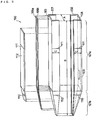
- FIG. 3 is an exploded perspective view of the measuring device according to this embodiment.
- a first member 201 and a second member 202, which form the measuring device 100, are made of transparent polystyrene and have a recess.
- the first member 201 and the second member 202 are combined together to form the housing 101 having the hollow quadrangular prismatic section 101a and the hollow quadrangular pyramidal section 101b.
- the first member 201 and the second member 202 can be obtained by molding using a mold. Known resin molding techniques may be used for molding. While the dimensions of the first member 201 and the second member 202 can be adjusted as appropriate, for example, the width A is 10 mm, the length B 84 mm, and the height C 6 mm.
- first reference line 110 and the second reference line 111 of this embodiment can be formed by printing as described above; however, they can be easily formed by molding the first member 201 using a mold that has portions corresponding to grooves or ribs which constitute the first reference line 110 and the second reference line 111.
- the first reference line 110 and the second reference line 111 can be formed after the production of the first member 201, the production of the housing 101, or the production of the conductive parts 105a and 105b.
- the reagent holding part 109 is formed on the bottom of the recess of the second member 202, i.e., on the inner wall of the fourth face 106.
- an antibody to human albumin is used as a reagent for optical measurement, and a certain amount of an aqueous solution of the antibody is applied to the bottom of the recess of the second member 202 by dropping it with a microsyringe, etc. This is then allowed to stand in an environment from room temperature to about 30°C to evaporate the water. In this way, the reagent can be carried thereon in a dry state.
- the above-mentioned antibody aqueous solution with a concentration of 8 mg/dL may be dropped in an amount of 0.7 mL onto an area of 5 cm 2 .
- the concentration and amount of the aqueous solution containing the reagent to be applied can be selected appropriately, according to the characteristics of the device required and the space restrictions on the formation position on the second member 202. Also, the area and position of the reagent holding part on the second member 202 can be selected appropriately in view of the solubility of the reagent in the sample, the position of the optical measurement part, etc.
- the antibody to human albumin can be obtained by conventional methods.
- an anti-human albumin antibody can be obtained by purifying an antiserum of a rabbit immunized with human albumin by protein A column chromatography and dialyzing it with a dialysis tube.
- the pair of conductive parts 105a and 105b is provided on the outer surface of the first member 201.
- the conductive parts 105a and 105b are mainly provided on the first face 105 of the hollow quadrangular prismatic section 101a and extend to the first face 115 of the hollow quadrangular pyramidal section 102b adjacent to the first face 105.
- These conductive parts 105a and 105b can be formed by placing an acrylic resin mask with openings of the same shape as the conductive parts 105a and 105b on the outer surface of the first member 201, sputtering gold over the mask, and removing the mask. Instead of sputtering, vapor deposition may also be used in the same procedure.
- the dimensions of the conductive parts 105a and 105b are not particularly limited, for example, the width can be approximately 2 mm, the length approximately 80 mm, and the thickness approximately 5 ⁇ m.
- the insulating resin cover 112 is attached to the conductive parts 105a and 105b so as to expose both ends of the conductive parts 105a and 105b.
- the cover 112 can be, for example, a PET film of approximately 10 mm in width, approximately 60 mm in length, and approximately 0.1 mm in thickness, with an acrylic adhesive applied thereto.
- the cover 112 is disposed such that the length of the electrodes and the cover is, for example, 10 mm.
- the material, area, thickness, shape, position, etc. of the conductive parts, the electrodes, and the connecting parts and the number (number of pairs) thereof can be adjusted as appropriate in view of the characteristics of the device required, the position of the optical measurement part, etc.
- glucose oxidase which is an enzyme
- an osmium complex which is an electron mediator
- glucose oxidase which is an enzyme
- an osmium complex which is an electron mediator
- a solution of polyvinylimidazole combined with osmium bis(bipyridine)chloride by coordinate bonding is mixed with a solution of glucose oxidase, and the resultant solution is applied onto the electrodes 105c and 105d.
- This solution on the electrodes 105c and 105d is then mixed with polyethylene glycol diglycidyl ether, which is an amine crosslinking agent. After a stand-by of approximately one hour, the surface of the electrodes 105c and 105d is washed with distilled water.
- the first member 201 and the second member 202 obtained in the above manner are bonded together in the positional relation as shown by the broken line in FIG. 3 , to fabricate the measuring device 100.
- the measuring device 100 is fabricated by applying an adhesive such as epoxy resin to the joint between the first member 201 and the second member 202, bonding the first member 201 and the second member 202 together, allowing them to stand, and drying them.
- first member 201 and the second member 102 together without applying an adhesive, and thermally or ultrasonically welding the joints between the first member 201 and the second member 102 by using a commercially available welding machine. In this way, the measuring device 100 illustrated in FIGs. 1 and 2 can be produced.
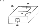
- FIG. 4 is a perspective view of the measuring apparatus of this embodiment
- FIG. 5 is a block diagram showing the configuration of the measuring apparatus of this embodiment
- FIG. 6 is a schematic cross-sectional view showing the main structure of the measuring apparatus of this embodiment into which the measuring device is inserted.
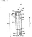
- FIG. 7 is a front view of a measuring-device eject mechanism of the measuring apparatus of this embodiment
- FIG. 8 is a side view of the same measuring-device eject mechanism.
- a measuring apparatus 300 of this embodiment has a measuring-device mounting part 301 for mounting the measuring device 100 in the measuring apparatus 300.
- the measuring-device mounting part 301 has a device mounting port (not shown) for detachably connecting with the sucking port 104 of the measuring device 100. It also has terminals (not shown) for electrically connecting with the connecting parts 105e and 105f.
- the measuring apparatus 300 contains: a light source 407 for emitting light which will enter the optical measurement part of the measuring device 100 mounted in the measuring-device mounting part 301; a light receiver 408, which is a light receiving unit for receiving the light that has exited from the optical measurement part; a voltage applying unit 402 for applying a voltage to the electrodes 105c and 105d of the measuring device 100; and an electrical signal measuring unit 405 for measuring the electrical signal from the electrodes 105c and 105d.
- the measuring apparatus 300 further contains: a CPU 401 which is a processor for detecting or quantifying an analyte contained in a sample based on at least one of the light received by the light receiver 408 and the electrical signal measured by the electrical signal measuring unit 405; and a piston mechanism 404 which is a suction unit for sucking the sample into the sample holding part 102 of the measuring device 100.
- a CPU 401 which is a processor for detecting or quantifying an analyte contained in a sample based on at least one of the light received by the light receiver 408 and the electrical signal measured by the electrical signal measuring unit 405
- a piston mechanism 404 which is a suction unit for sucking the sample into the sample holding part 102 of the measuring device 100.
- the light source 407 can be, for example, a semiconductor laser which emits light with a wavelength of 650 nm. Instead of this, for example, a light emitting diode (LED) may be used.
- LED light emitting diode
- 650 nm is selected as the wavelength of light emitted and received, but this wavelength can be selected appropriately according to the measurement method and the measuring object.
- the light receiver 408 can be, for example, a photodiode.
- the light receiver 408 may be, for example, a charge-coupled device (CCD) or a photomultiplier.
- the piston mechanism 404 is configured such that the piston is operated by a linear stepper motor.
- the measuring apparatus 300 further contains a memory 409, which is a storage device that stores data on a first calibration curve representing the relation between the concentration of human albumin, which is the first analyte, and the intensity of light received by the light receiver 408 and data on a second calibration curve representing the relation between the concentration of glucose, which is the second analyte, and the electrical signal measured by the electrical signal measuring unit 405.
- a memory 409 which is a storage device that stores data on a first calibration curve representing the relation between the concentration of human albumin, which is the first analyte, and the intensity of light received by the light receiver 408 and data on a second calibration curve representing the relation between the concentration of glucose, which is the second analyte, and the electrical signal measured by the electrical signal measuring unit 405.
- the measuring device 100 is inserted into the measuring apparatus 300 through the measuring-device mounting part 301 (see FIG. 4 ). As illustrated in FIG. 6 , the measuring device 100 pushes a slide member 501 upward in FIG. 6 , and the measuring device 100 mates with a device mounting port 504, which is composed of a protrusion 502a that protrudes from a frame member 502 for mounting the device and a sealing member 503 that is fitted to the outer periphery of the protrusion 502a for mounting the device.
- the protruding device mounting port 504 is inserted into the sucking port 104, so that a push protrusion 501a of the slide member 501 presses a switch 505 for detecting insertion of the measuring device. When the measuring-device insertion detecting switch 505 is pressed, completion of the mounting of the measuring device 100 into the measuring apparatus 300 is detected.
- the shapes of the outer edge of the device mounting protrusion 502a and the outer edge of the device mounting sealing member 503, i.e., the shapes of their cross-sections in the direction perpendicular to a longitudinal central axis 506 are similar to the shape of the inner face of the sucking port 104 of the measuring device 100.
- the size of the outer edge of the device mounting sealing member 503 is made slightly larger than the size of the sucking port 104 of the measuring device 100, thereby enhancing the adhesion between the device mounting sealing member 503 and the sucking port 104 and preventing leakage of air in the joint thereof.
- the device mounting sealing member 503 is made of, for example, an elastic material such as isoprene rubber, fluorocarbon rubber, silicone rubber, or Teflon (registered trademark) coating rubber.
- the sealing member may be linear or the protruding device mounting port 504 itself may be composed of an elastic material.
- the frame member 502 has a protrusion 502b for mounting a cylinder on the side opposite to the device mounting protrusion 502a.
- a sealing member 507 for mounting a cylinder made of the same material as the device mounting sealing member 503, is fitted around the cylinder mounting protrusion 502b to provide gas tightness.
- a cylinder 600 which contains a piston 509 to which a piston rod 508 is fixed, is fitted to the cylinder mounting protrusion 502b of the frame member 502 with the cylinder mounting sealing member 507 therebetween to provide gas tightness.
- the piston rod 508 has a female thread 508a in the center thereof, and has a key groove 508b on the outer periphery in the longitudinal direction.
- the key groove 508b is engaged with a protrusion 600a, which is at the opposite end of the cylinder 600 from the joint with the cylinder mounting sealing member 507, so that the piston rod 508 can move linearly without rotation.
- a male thread 602 fixed to the rotational shaft of a motor 601 is screwed to the female thread 508a of the piston rod 508, so that due to the rotation of the male thread 602 caused by the rotation of the motor 601, the piston rod 508 having the female thread 508a screwed to the male thread 602 can move linearly along the longitudinal central axis 506 upward and downward in the figure.
- the cylinder 600 having the piston 509 to which the piston rod 508 is fixed, the male thread 602 screwed to the female thread 508a of the piston rod 508, and the motor 601 to which the male thread 602 is fixed constitute the piston mechanism 404, which is the suction unit for sucking a sample into the measuring device 1.
- a sample can be easily supplied to the sample holding part 102 of the measuring device 100 by sucking the sample from the sample supply inlet 104 of the measuring device 100 using the piston mechanism 404 serving as the suction unit.
- the measuring apparatus 300 includes the light source 407 for emitting light that will enter the optical measurement part, which is composed of the light entrance of the second face 107 and the light exit of the third face 108 of the measuring device 100 mounted in the measuring apparatus 300, and the light receiver 408 serving as the light receiving unit for receiving light that has exited from the optical measurement part.
- the light emitted from the light source 407 passes through the light entrance of the second face 107 of the measuring device 1, the sample supplied to the sample holding part 102 of the measuring device 100, and the light exit of the third face 108 of the measuring device 100, and is received by the light receiver 408.
- the light receiver 408 produces an electrical signal corresponding to the intensity of the light it received.
- the positions of the light source 407 and the light receiver 408 are determined so that in the optical path of light which is emitted from the light source 407 and received by the light receiver 408, the spots of light passing through the light entrance and the light exit of the measuring device 100 are positioned away from the joints between the first member 201 and the second member 202 of the measuring device 100.
- the slide member 501 has push pins 501b and 501c, for example, on the faces corresponding to the opposing first face 105 and fourth face 106 of the measuring device 100, respectively.
- FIG. 8 is a view seen from the direction of the arrow Y in FIG. 7 .
- Drive levers 611 and 612 have, at their ends, long holes 611a and 612a (not shown) to which the push pins 501b and 501c are slidably engaged, respectively.
- the drive levers 611 and 612 are installed so as to swing on a fixed fulcrum shaft 613.
- the drive levers 611 and 612 are shaped like substantial Z and reversed substantial Z, respectively, when seen from the direction of the arrow X.
- the drive levers 611 and 612 are joined so as to face each other on the opposite side of the long holes 611a and 612a formed at the ends thereof, while the ends of the drive levers 611 and 612 with the long holes 611a and 612a are apart from each other such that they engage with the push pins 501b and 501c of the slide member 501.
- long holes 611b and 612b are formed at the same position of the drive levers 611 and 612 so that they align together. They are coupled to a plunger 616 of a solenoid 615 by means of working pins 614 engaged in the long holes 611b and 612b.
- a measuring-device eject mechanism 617 is composed of the slide member 501, the drive levers 611 and 612 which swing on the fulcrum shaft 613, the working pins 614, and the solenoid 615 having the plunger 616 which swings the drive levers 611 and 612.
- a current is supplied to the solenoid 615.
- the plunger 616 is sucked and the drive levers 611 and 612 are swung via the working pins 614 counterclockwise in the figure.
- the push pins 501b and 501c of the slide member 501 are pushed via the long holes 611a and 612a of the drive levers 611 and 612, so that the slide member 501 is moved downward in the figure.
- the slide member 501 has push projections 501d at least at two locations near the push pins 501b and 501c, and the push projections 501d are in contact with the end of the measuring device 100.
- the measuring device 100 is moved downward in the figure. As a result, it is possible to disconnect the measuring device 100 from the device mounting port 504 and detach the measuring device 100 from the measuring apparatus 300.
- the sucking port 104 of the measuring device 100 is joined to the device mounting port 504 in the measuring-device mounting part 301 of the measuring apparatus 300, in order to mount the measuring device 100 in the measuring-device mounting part 301.
- the connecting parts 105e and 105f come into contact with two terminals 606 and 607 inside the measuring-device mounting part 301 to electrically connect the two electrodes 105c and 105d of the measuring device 100 with the two terminals, respectively.
- the measuring-device insertion detecting switch 505 which is a microswitch inside the measuring apparatus 300, is turned on.
- the CPU 401 which functions as a controlling unit, detects the insertion of the measuring device 100 and a voltage (e.g., a voltage such that the electrode 105c is at +0.2 V relative to the electrode 105d) is applied between the two electrodes 105c and 105d of the measuring device 100 by the voltage applying unit 402.
- the measuring device 100 is immersed in, for example, urine collected in a portable container such as a urine container or paper cup placed in a toilet bowl, up to at least the position of the first reference line 110, in order to immerse the sample supply inlet 103 and the two electrodes 105c and 105d of the measuring device 100 in the urine.
- a current flows between the two electrodes, and a resulting change in electrical signal is detected by the electrical signal measuring unit 405.
- the voltage applied by the voltage applying unit 402 is switched to a different voltage (e.g., a voltage such that the electrode 105c is at +0.5 V relative to the electrode 105d).
- the CPU 401 makes a time measuring unit 406, which is a timer, start time measurement.
- the CPU 401 determines from the signal sent from the time measuring unit 406 that a predetermined time (e.g., 15 seconds) has passed, electrical signal such as the current flowing between the electrode 105c and the electrode . 105d is measured by the electrical signal measuring unit 405.
- the CPU 401 converts the measured electrical signal into glucose concentration in the urine by reading the second calibration curve representing the relation between electrical signal and glucose (urine sugar) concentration stored in the memory 409 and referring to it.
- Glucose oxidase which is an enzyme
- an osmium complex which is an electron mediator
- the glucose concentration obtained is displayed on the display 302.
- the user can know the completion of the glucose concentration measurement.
- the sample supply inlet 103 can be pulled out of the urine.
- the CPU 401 determines that the sample supply inlet 103 has been immersed in the sample and makes the piston mechanism 404 function. As a result, the piston in the piston mechanism 404 moves and a predetermined amount (e.g., 3 mL) of the urine is sucked from the sample supply inlet 103 of the measuring device 100 into the sample holding part 102.
- a predetermined amount e.g., 3 mL
- the user may press the sample-suction start button 303 to operate the piston mechanism 404 when having confirmed that at least the sample supply inlet 103 is immersed in the urine, in order to suck the urine into the sample holding part 102.
- the electrical signal measuring unit 405 redetects a change in electrical signal, so the piston mechanism 404 is stopped upon the detection. This makes it possible to prevent the sample in the sample holding part 102 from being continuously sucked by the piston mechanism 404 when the two electrodes 105c and 105d are out of the urine and thus prevent the sample from mistakenly entering the piston mechanism 404.
- the urine supplied to the sample holding part 109 dissolves the dry reagent carried on the reagent holding part 109, i.e., anti-human albumin antibody, so that an immune reaction between the antigen in the urine, i.e., human albumin, and the anti-human albumin antibody proceeds.
- the CPU makes the time measuring unit 406, which is a timer, start time measurement.
- the CPU 401 determines from the signal sent from the time measuring unit 406 that a predetermined time (e.g., 2 minutes) has passed from the completion of the supply of sample to the sample holding part 102, the CPU 401 makes the light source 407 emit light.
- a predetermined time e.g. 2 minutes
- the light emitted by the light source 407 passes through the light entrance 107 of the measuring device 100 and enters the sample holding part 102. It then passes through the urine and scatters.
- the light having exited from the light exit 108 is received by the light receiver 408 disposed in the measuring apparatus 300 for a predetermined time (e.g., 3 minutes).
- the CPU 401 converts the intensity of the outgoing light received by the light receiver 408 into human albumin concentration by reading the first calibration curve representing the relation between outgoing light intensity and human albumin concentration stored in the memory 409 and referring to the first calibration curve.
- the human albumin concentration obtained is displayed on the display 302. Then, the user can know the completion of the human albumin concentration measurement.
- the urine sugar concentration and human alubumin concentration obtained are stored in the memory 409 together with the time measured by the time measuring unit 406.
- the urine sugar concentration and human albumin concentration obtained can be recorded onto a recording medium such as an SD card by a recording unit 411.
- a recording medium such as an SD card
- the measurement results can be readily taken out of the measuring apparatus 300. It is thus possible to bring or mail the recording medium to an analytical laboratory for analysis.
- the urine sugar concentration and human albumin concentration obtained can be transmitted from the measuring apparatus 300 to outside by a transmitter 412.
- the measurement results can be transmitted to an analytical division in a hospital, analytical service, etc, so that they can be analyzed by the analytical division, analytical service, etc. It is therefore possible to shorten the time required from measurement to analysis.
- receiver 413 for receiving the results of analysis by the analytical division, analytical service, etc. It is therefore possible to promptly feed back the results of analysis to the user.
- a measuring-device eject mechanism 410 functions and causes the piston in the piston mechanism 404 to move.
- the urine in the sample holding part 102 is discharged from the sample supply inlet 103 into a toilet bowl or a container such as a paper cup, and then the measuring device 100 is automatically detached from the measuring apparatus 300.
- the measuring device 100 may be manually detached from the measuring-device mounting part 301 by the user, without providing the measuring device with such a mechanism for detaching the device and discharging the sample.
- the reagent holding part 109 on the inner surface of the housing 101 of the measuring device 100 and providing the electrodes 105c and 105d on the outer surface of the housing 101, the reagent necessary for the optical measurement is prevented from diffusing into the electrodes and thus affecting the electrochemical measurement. It is thus possible to measure a plurality of test items promptly and correctly.
- the shape of the measuring device 100 is not limited to the one described in the above embodiment as long as the requirements of the present invention are satisfied and the effects of the present invention can be obtained.
- FIG. 9 is a perspective view showing a first modified example of the measuring device of the above embodiment
- FIG. 10 is a cross-sectional view of the B-B part of FIG. 9 .
- the same constituent elements as those in FIGs. 1 and 2 are given the same reference characters and explanations thereof are omitted.
- a measuring device 100 of this modified example includes a housing 101 with a bottom, which is in the shape of a hollow rectangular parallelepiped having therein a space serving as a sample holding part 102.
- the housing 101 has a sample supply inlet 103 in a first face 105.
- the housing 101 of this modified example includes a member (first member) 201 having a first face 105, a second face 107, a third face 108, and a bottom, and a back plate (second member) 202.
- the pair of electrodes 105c and 105d has been described, but this is not to be construed as limiting, and the number of electrodes and pairs can be changed as appropriate, if necessary.
- a second modified example of the measuring device of the above embodiment having a plurality of pairs of electrodes is briefly described with reference to FIG. 11 .
- FIG. 11 the elements corresponding to the constituent elements in FIG. 1 and FIG. 2 are given the same reference characters as those in FIG. 1 and FIG. 2 .
- a first face 105 is provided with conductive parts 105a and 105b for forming a pair of electrodes 105c and 105d and corresponding connecting parts 105e and 105f.
- the first face 105 is opposed to a fourth face 106 whose outer surface is provided with conductive parts 701a and 701b for forming a pair of electrodes 701c and 701d and corresponding connecting parts 701e and 701f.
- a cover 702 is disposed so as to define the areas of the electrodes 701c and 701d in the same manner as a cover 112 attached to the first face 105, and detailed explanation thereof is omitted. It is preferable to use respective pairs of electrodes (two pairs of electrodes in this description) to quanitify different analytes. For example, one pair of electrodes 105c and 105d may be used to measure the salt concentration by conductivity, and the other pair of electrodes 701c and 701d may be used to measure urine sugar. Further, in the case of using an additional pair of electrodes, for example, creatinine may be additionally measured. Combinations of analytes are not to be limited to these examples, and substances that need to be measured may be selected as appropriate.
- the method of disposing the insulating resin cover 112 on the conductive parts 105a and 105b so as to expose both ends of the conductive parts 105a and 105b in order to form the electrodes 105c and 105d and the connecting parts 105e and 105f has been described, but this is not to be construed as limiting.
- a cover 704 has an opening 706 at the position corresponding to electrodes 105c and 105d, and the opening 706 is formed so as to have a length D such that the length dimension of the pair of electrodes 105c and 105d exposed from the opening 706 is a predetermined dimension. It is also possible to use a method of attaching the cover 704 with the opening 706 onto the conductive parts 105a and 105b to form the pair of electrodes 105c and 105d and connecting parts 105e and 105f.
- the cover 704 of such shape By using the cover 704 of such shape, even if the bonding position of the cover 704 is slightly displaced, the areas of the exposed parts of the electrodes 105c and 105d become constant, and accurate measurements are possible.
- the shape of the opening is rectangular, but it may be circular, triangle, polygonal, or oval.
- FIG. 13 and FIG. 14 a fourth modified example of the measuring device of the above embodiment is described with reference to FIG. 13 and FIG. 14 .
- the elements corresponding to the constituent elements in FIG. 1 and FIG. 2 are given the same reference characters as those in FIG. 1 and FIG. 2 .
- a measuring device 100 includes a housing 101 with a bottom, which is in the shape of a hollow rectangular parallelepiped having therein a space serving as a sample holding part 102.
- the housing 101 is composed of a first member 201 with a first face 105, a second face 107, a third face 108, and a bottom 708, and a second member 202 which is a back plate constituting a fourth face 106.
- a pair of electrodes 105c and 105d is formed on the first face 105
- a sample supply inlet 103 is formed in the fourth face 106 which is opposed to the first face 105
- a reagent holding part 109 for holding a reagent is formed on the inner face of the first member 201, i.e., the face forming a sample holding part 102.
- a pair of conductive parts 105a and 105b is formed on the outer surface of the first face 105, and a cover 112 is attached such that the electrodes 105c and 105d and connecting parts 105e and 105f are formed at opposite ends of the conductive parts 105a and 105b, respectively.
- a first reference line 110 and a second reference line 111 are formed on the housing 101 and the cover 112.
- the reagent holding part 109 was formed by applying an aqueous solution containing a reagent for optical measurement and drying it.
- a method of impregnating a porous carrier made of glass fiber, filter paper, etc. with a solution of a reagent, drying or freeze drying it to carry the reagent, and attaching the porous carrier to the bottom of the recess of the first member 201 to carry the reagent.
- the method of forming the conductive parts 105a and 105b, the electrodes 105c and 105d, and the connecting parts 105e and 105f by sputtering or vapor deposition was described. Instead, it is possible to use a method of attaching a metal ribbon to the outer surface of the first member 201, a method of printing an ink containing metal or carbon onto the outer surface of the first member 201, etc..
- the voltage value was changed, but such changing is not always necessary. If a voltage necessary for measurement is applied before a sample is supplied, the voltage can be continuously applied after the supply.
- the present invention can provide a measuring device, a measuring apparatus, and a measuring method capable of measuring a plurality of test items promptly and accurately by performing optical and electrochemical measurements of a sample using a simple configuration. Therefore, the present invention is useful in the medical and medical related test fields, in particular, for measuring urine specimens.
Description
- The present invention relates to a measuring device, a measuring apparatus, and a measuring method for analyzing an analyte contained in a sample, having, respectively, the features of the preambles of
claim 1, 7 and 9. - Measuring instruments conventionally used in the field of clinical tests are mainly large-sized automated devices and POCT (Point of Care Testing) devices.
- Large-sized automated devices are installed in hospital clinical laboratories and commercial clinical laboratories and capable of testing samples of many patients for a large number of items (e.g., see Patent Document 1). For example, a large-sized automated device of Hitachi 7170 is capable of performing 800 tests per hour for up to 36 items. Thus, they contribute to higher test efficiency and are equipment suited for hospitals with a large number of examinees.
- Meanwhile, POCT devices refer to devices used in clinical tests that are conducted in medical settings other than hospital laboratories and test centers, and include devices for use in home healthcare (e.g., see Patent Document 2 and Patent Document 3). Such examples include blood sugar sensors, pregnancy test drugs, ovulation test drugs, and HbA1c/microalbumin analyzers (e.g., DCA 2000 available from Bayer AG). These POCT devices are inferior in versatility to large-sized automated devices, but are capable of focusing on a marker substance specific to a disease and measuring the marker substance in a simple and prompt manner. They are thus effective for screening and monitoring examinees. Also, POCT devices are small and portable, can be introduced at low costs, and can be used by anyone without requiring particular expertise in operation.
- Currently, there are many items measured in clinical tests. When a body fluid such as urine is used as a sample, the measurement methods are roughly divided into optical measurement type and electrochemical measurement type. The above-described conventional large-sized automated devices and POCT devices use either type of measurements for making measurements.
- Recently, swelling medical expenses and an increasing number of patients with life-style related diseases have been imposing a burden on medical economy, thereby necessitating a reduction in medical expenses and suppression of increasing patients with lifestyle-related diseases. One fundamental solution of such problem could be Evidence Based-medical (EBM). EBM allows objective management of medical care according to individual patients' needs, and it is expected that practicing preventive healthcare will lead particularly to a reduction in the number of patients with lifestyle-related diseases, etc.
- To establish and practice EBM, test information obtained from clinical tests is essential. Test information in EBM includes test results and solutions for patients based on the test results. As used herein, "solutions for patients" refer to guidance on lifestyle such as diet control, treatment by medication, and the like. That is, in EBM, tests are conducted in order to allow those who are to receive medical care to "find their problems" and "make a decision on courses of treatment". In order to provide safer and better solutions in EBM, it is necessary to clearly present problems to those who are to receive medical care. Hence, in clinical tests, it has become important to obtain the test results of a plurality of interrelated test items easily and promptly.
- The above-described conventional large-sized automated devices are versatile and capable of testing a large number of items regardless of whether or not they are related to a disease. However, since such devices have complicated structures, they are difficult to operate for those without expertise. Further, there is a problem in that it takes long time to obtain a test result so that it takes long time to feed back the result to the examinee. Also, although the POCT devices are superior in operability and capable of easy and prompt tests, they are unable to test a plurality of items, since they are measurement devices designed specifically for markers that are related to specific diseases.
- Thus, there has been proposed a device for use in biochemical or clinical tests, which includes a cavity into which a liquid sample flows by capillary action. The cavity includes an electrode structure for measuring at least one electrical characteristic of the sample, and a reagent such as an antibody or enzyme capable of being released into the cavity. A wall of the cavity is transparent so that the cavity contents can be optically measured (e.g., Patent Document 4).
- Patent Document 1:
JP-No. Hei 09-127126 - Patent Document 2:
JP-No. Hei 07-248310 - Patent Document 3:
JP-No. Hei 03-046566 - Patent Document 4:
U.S. No. 5,141,868 - As to further prior art,
US 2004-191119 A describes arrangements for the detection of the presence and/or concentration of an analyte in a sample of bodily fluid, which include diffuse transmission, diffuse reflection and edge or waveguide illumination arrangements. Furthermore, a vertical flow assay arrangement or vertical flow assay technique is disclosed, which includes, inter alia, a detection component in the form of an array of optical detection elements. -
FR 2 611 906 A -
EP 0 545 284 A describes a sample measuring device comprising an injection port for injecting a sample, an sample accumulation portion having a reagent carrier enclosed, a flow passage portion with a light receiving element, for passing a reaction fluid from the accumulation portion therethrough, a micro-pump for feeding the sample fluid within the flow passage portion and which is a heat generating element provided near a nozzle downstream of a measuring position in the flow passage portion. - Furthermore,
US 5,844,686 A discloses a hand apparatus for pipetting and photometrically evaluating samples which comprise a pipetting means, an integrated photometer and a replaceable pipette tip connected to said pipetting means, said pipette tip being defined as a cell and provided within the optical path of the photometer for photometrically evaluating absorbed samples. -
US 5,045,286 A discloses a device for injecting a fixed quantity of sample liquid is provided with a unit for aspirating and injecting sample liquid. The sample aspirating and injection unit has a nozzle connecting portion. The liquid injection device is provided with an injection nozzle attached to and detachable from the nozzle connecting portion of the sample aspirating and injecting unit and electrodes are attached to the injection nozzle. Conductive members which are electrically connected to the electrodes of the injection nozzle are attached to the nozzle connecting portion of the sample aspirating and injecting unit, and a detecting unit which cooperates with the electrodes to detect the surface level of sample liquid is connected to the conductive members. - However, the structure of the device of Patent Document 4 has a problem in that the reagent used for the optical measurement dissolves in the sample supplied in the cavity and reaches the electrode structure, thereby adversely affecting the measurement of the electrical characteristic by the electrode structure.
- Therefore, in view of the conventional problems as described above, an object of the present invention is to provide a measuring device, a measuring apparatus, and a measuring method capable of measuring a plurality of test items promptly and accurately by performing optical and electrochemical measurements of a sample using a simple configuration. The object of the present invention is solved by a measuring device according to
claim 1, a measuring apparatus according to claim 7 and a measuring method according to claim 9. - In particular, the present invention provides a measuring device having the features of
claim 1 of the invention, for being mounted in a measuring apparatus for analyzing analytes contained in a sample. - The present invention also provides a measuring apparatus having the features of claim 7 of the invention.
- The present invention also provides a method for measuring a first analyte and a second analyte contained in a sample by using the above-described measuring device. The method having the features of claim 9 of the invention.
- The present invention can provide a measuring device, a measuring apparatus, and a measuring method capable of measuring a plurality of test items promptly and accurately by performing optical and electrochemical measurements of a sample.
-
-
FIG. 1 is a perspective view showing the structure of one embodiment of a measuring device according to the present invention; -
FIG. 2 is a cross-sectional view of the A-A part ofFIG. 1 ; -
FIG. 3 is an exploded perspective view of themeasuring device 100 of the present invention illustrated inFIG. 1 ; -
FIG. 4 is a perspective view showing the structure of one embodiment of a measuring apparatus according to the present invention; -
FIG. 5 is a block diagram showing the configuration of the measuring apparatus of the present invention illustrated inFIG. 4 ; -
FIG. 6 is a cross-sectional view showing the structure of the same measuring apparatus into which the measuring device is inserted; -
FIG. 7 is a front view of a measuring-device eject mechanism of the same measuring apparatus; -
FIG. 8 is a side view of the measuring-device eject mechanism of the same measuring apparatus; -
FIG. 9 is a perspective view showing the structure of one modified example of the measuring device according to the present invention; -
FIG. 10 is a cross-sectional view of the B-B part ofFIG. 6 ; -
FIG. 11 is an exploded perspective view showing the structure of another modified example of the measuring device according to the present invention; -
FIG. 12 is a front view of still another modified example of the measuring device according to the present invention; -
FIG. 13 is a perspective view showing the structure of still another modified example of the measuring device according to the present invention; and -
FIG. 14 is a cross-sectional view of the B-B part ofFIG. 13 . - The measuring device of the present invention includes the features of
claim 1. - With this configuration, by supplying a sample to the sample holding part once, it is possible to perform optical and electrochemical measurements of the sample by using one measuring device. By carrying the reagent on the inner surface of the housing, disposing the at least one electrode on the outer surface of the housing, and bringing the sample into contact with the at least one electrode on the outer surface, it is possible to perform optical and electrochemical measurements. Hence, the reagent necessary for the optical measurement is prevented from diffusing to the electrode and affecting the electrochemical measurement, so that a plurality of test items can be measured promptly and correctly.
- The light entrance and the light exit are preferably made of an optically transparent material or a material that does not substantially absorb visible light. Such examples include quartz, glass, polystyrene, and polymethyl methacrylate. When the sensor is made disposable, polystyrene is preferable in terms of costs.
- Preferable materials for the electrode are those containing at least one of gold, platinum, palladium, alloys thereof, mixtures thereof, and carbon. Alternatively, indium tin oxide (ITO) is preferable as a transparent electrode. Since these materials are chemically and electrochemically stable, they can realize stable measurements.
- Also, the electrode is an electrode for measuring the concentration of a specific compound or ion contained in a sample. With this configuration, the concentration of a specific compound or ion in a sample can be obtained. For example, by using a glass electrode or the like, the concentration of sodium ion can be measured.
- Further, the electrode is preferably an electrode having a membrane sensitive to a specific ion contained in a sample (ion-sensitive membrane). With this configuration, the concentration of a specific ion in a sample can be obtained.
- The ion-sensitive membrane can be one having a function of selectively allowing one of such ions as sodium ion, potassium ion, lithium ion, magnesium ion, calcium ion, chloride ion, ammonium ion, and hydrogen ion to pass through.
- The compound forming the ion-sensitive membrane can be a known compound suitable for the ion to be passed through. For example, the following ion-selective inclusion compounds can be used: for sodium ion, bis[(12-crown-4)methyl]2,2-dibenzomalonate etc.; for potassium ion, bis[(benzol5-crown-5)4-methyl]pimelate etc.; for lithium ion, phosphododecyl-14-crown-4 etc.; for magnesium ion, 4,13-bis[N-(1-adamantyl)carbamoylacetyl]-8-tetradecyl-1,7,10,16-tetraoxa-4,13-diazacyclooctadecane etc.; for calcium ion, 4,16-bis(N-octadecylcarbamoyl)-3-octbutyryl-1,7,10,13,19-pentaoxa-4,16-diazacyclohenicosane etc.; for chloride ion, 2,7-di-tert-butyl-9, 9-dimethyl-4,5-bis (N-n-butylthioureylene)xanthene etc.; and for ammonium ion, 2,6,13,16,23,26-hexaoxaheptacyclo [25.4.4.47,12.417,22.01,17.07,12.017,22] tritetracontane etc. They are available, for example, from DOJINDO LABORATORIES as commercial products.
- An example of methods of forming the ion-sensitive membrane on the electrode is a method of dissolving such an inclusion compound, a plasticizer, an anion remover, and a polymer compound such as PVC in an organic solvent, applying the resultant mixture solution onto the electrode, and drying it by air or the like.
- The electrode may be a field-effect transistor (FET) electrode formed of silicon or the like. Also, a reference electrode with stable potential, for example, a Ag/AgCl or saturated calomel electrode is preferably used as one electrode or a third electrode in combination with other electrode.
- Also, an enzyme is preferably carried on the electrode. Since an enzyme highly selectively catalyzes the reaction of a specific compound, a highly selective measurement of a specific compound in a sample can be realized. A known optimum enzyme in terms of selectivity and reactivity is used depending on the compound to be measured.
- Examples of enzymes include glucose oxidase, glucose dehydrogenase, alcohol oxidase, cholesterol oxidase, and sarcosine oxidase. These enzymes are commercially available. Also, the use of cholesterol esterase in combination with cholesterol oxidase allows detection of ester-type cholesterol. Alternatively, the use of creatininase and creatinase in combination with sarcosine oxidase permits quantification of creatinine, creatine, or sarcosine.
- In the present invention, the enzyme is preferably immobilized to the electrode without dissolving in the sample. With this configuration, even if there are variations in the amount of sample, accurate measurements are possible.
- Also, if necessary, an electron mediator allowing electron transfer between the enzyme and the electrode, for example, ferri/ferrocyanide ion, a ferrocene derivative, a ruthenium complex, an osmium complex, or a quinone derivative may be used. When the enzyme is immobilized to the electrode, it is more preferable to immobilize the electron mediator together.
- In the measuring device of the present invention, the reagent preferably includes an enzyme or antibody. The reagent is preferably disposed such that it is placed in a dry state in the sample holding part and dissolved in a sample when the sample is supplied to the sample holding part.
- For example, a porous carrier made of glass fiber, filter paper, etc., is impregnated with a solution of the reagent and dried to carry the reagent on the carrier, and the carrier is disposed in the sample holding part. Also, the reagent may be disposed by directly applying a solution of the reagent to a wall face of the sample holding part and drying it.
- An antibody as a reagent can be produced by known methods and is thus advantageous in that the reagent can be easily prepared. For example, by immunizing a mouse, a rabbit or the like using a protein such as albumin or a hormone such as hCG or LH as an antigen, an antibody to the antigen can be obtained.
- Examples of antibodies include an antibody to a protein contained in urine, such as albumin, and an antibody to a hormone contained in urine, such as hCG or LH. If necessary, a compound which promotes the coagulation reaction between an antigen and an antibody, such as polyethylene glycol, may be provided in the vicinity of the antibody in the measuring device.
- An enzyme as a reagent highly selectively catalyzes the reaction of a specific compound, and hence a highly selective measurement of a specific compound in a sample can be realized. A known optimum enzyme in terms of selectivity and reactivity is used depending on the compound to be measured.
- Examples of enzymes include glucose oxidase, glucose dehydrogenase, alcohol oxidase, cholesterol oxidase, sarcosine oxidase, and other oxidoreductases. In this case, by providing a colorant or colorant source whose color changes or disappears as a result of enzyme reaction together with the enzyme, the optical measurement is stabilized. These enzymes are commercially available. Also, the use of cholesterol esterase in combination with cholesterol oxidase permits detection of ester-type cholesterol. Also, the use of creatininase and creatinase in combination with sarcosine oxidase allows quantification of creatinine, creatine, or sarcosine.
- The housing of the measuring device of the present invention preferably has a first reference line that indicates a position up to which the housing is to be immersed in the sample when the measuring device is immersed in the sample. With this configuration, the user can easily find up to which part of the measuring device the user should immerse the measuring device in the sample.
- The first reference line is preferably provided such that at least a part of the electrode is positioned between the sample supply inlet and the first reference line. With this configuration, when the measuring device is immersed in the sample up to the position of the first reference line, it is possible to ensure that at least a part of the electrode comes into contact with the sample.
- Also, the housing of the measuring device of the present invention preferably has a second reference line that indicates the amount of the sample to be supplied to the housing. With this configuration, when the sample is supplied to the sample holding part, it is possible to check whether a predetermined amount of sample is held in the sample holding part.
- Also, preferably, the measuring device of the present invention further includes conductive members disposed on the outer surface of the housing and a cover that covers the conductive members so as to expose a part of each of the conductive members, so that the parts of the conductive members exposed without being covered by the cover (the above-mentioned part) function as the electrodes. That is, the exposed parts correspond to the electrodes. With this configuration, since the electrode area can be defined by using the cover, highly quantitative electrochemical measurements are possible. Also, each of the conductive members may have a plurality of parts that are exposed without being covered by the cover, so that at least one of the plurality of parts can function as the electrode.
- Also, the measuring apparatus of the present invention includes the features of claim 9.
- Preferably, the measuring device is detachably mounted in the measuring apparatus. Also, the measuring device is preferably disposable.
- The measuring device includes a sucking port for sucking the sample into the sample holding part from the sample supply inlet. With this configuration, by mounting the measuring device such that the sucking port of the measuring device is connected to the measuring-device mounting part, and by using the suction unit, a sample can be easily supplied to the sample holding part of the measuring device from the sample supply inlet.
- The sucking unit may be manual or automatic and may be, for example, a piston mechanism such as a conventional syringe or dispenser.
- The piston of such a piston mechanism may be operated manually or automatically, but automatic operation is preferable since it can reduce the workload of the operator. Automation methods include a method of operating the piston by means of a motor. The motor may be a stepper motor, a DC motor, etc.
- A stepper motor is a motor that rotates by a particular rotation angle per input pulse signal and the rotation angle can be determined by the number of pulses. Thus, it does not need an encoder for positioning. That is, the operation distance of the piston can be controlled based on the number of input pulses.
- The rotational motion of the motor is converted to linear motion by using, for example, a linear motion mechanism consisting of a gear mechanism combined with male and female threads, to operate the piston. The rotational motion of a DC motor is also converted to linear motion in the same manner, but a DC motor needs an encoder that detects the rotational position of the motor in order to control the operation distance of the piston. There is also a linear stepper motor. In the case of this type of motor, the motor contains a linear motion mechanism consisting of combined male and female threads, and a movable bar moves linearly depending on the number of input pulses. Thus, the piston can be directly connected to this bar, which makes the structure simple.
- Also, the measuring method of the present invention is a method according to claim 9.
- In the step (A), with the measuring device being immersed in the sample such that the sample and the electrodes are in contact with each other, the application of the voltage to the electrodes may be started. Alternatively, after the application of the voltage to the electrodes is started, and with the voltage being applied, the measuring device may be immersed in the sample such that the sample and the electrodes are in contact with each other.
- It is preferable to detect a change in the electrical signal in the step (B) and automatically perform the step (C) based on the detection.
- In this case, by detecting a change in the electrical signal in the electrodes, it is possible to detect that the sample supply inlet of the measuring device has been immersed in the sample. It is therefore possible to prevent the sample from being mistakenly sucked before the sample supply inlet is immersed in the sample.
- It is also preferable to perform the step (B) while performing the step (C), detect a change in the electrical signal in the step (B), and automatically stop the sucking of the sample based on the detection. In this case, by detecting a change in the electrical signal in the electrodes while sucking the sample, it is possible to detect that the measuring device has been pulled out of the sample. By automatically stopping the sucking of the sample based on the detection, it is possible to prevent the sucking of the sample from being continued when the sample is away from the sample supply inlet.
- Further, based on one of the quantification result of the first analyte and the quantification result of the second analyte, the other quantification result is preferably corrected.
- In this case, by measuring a plurality of interrelated test items, the accuracy of measurement results can be enhanced. Exemplary combinations of a first analyte and a second analyte include a combination of blood sugar and HbA1c, a combination of a urine component such as albumin or urine sugar and creatinine.
- Examples of samples used in the present invention include body fluids such as serum, plasma, blood, urine, interstitial fluid, and lymph, and liquid samples such as supernatant fluid of a culture medium. Also, a mixture of a body fluid and a reagent which reacts with a specific component in the body fluid, such as an enzyme, antibody, or colorant, may be supplied to the measuring device as the sample.
- Among them, urine is preferable as the sample. When the sample is urine, daily health management can be made at home in a noninvasive manner.
- Examples of the first analyte include albumin, hCG, LH, CRP, and IgG. Also, examples of the second analyte include sodium ion, potassium ion, lithium ion, magnesium ion, calcium ion, chloride ion, ammonium ion, hydrogen ion, and glucose.
- In a qualitative analysis of urine, which is conducted in an initial stage of health management, twelve items, namely pH, specific gravity, protein, sugar, occult blood, ketone body, bilirubin, urobilinogen, nitrite, leukocyte, ascorbic acid, amylase, and salt are tested. Also, microalbumin is tested to assess kidney function, and hormones such as hCG and LH are tested as markers for pregnancy/ovulation tests etc.
- Among these test items, protein, microalbumin, and hormones such as hCG and LH are suited for optical measurements based on antigen-antibody reaction. Examples of optical measurements based on antigen-antibody reaction include measurements of turbidity in a sample caused by antigen-antibody reaction, such as nephelometric immunoassay, turbidimetric immunoassay, and latex agglutination immunoassay.
- Meanwhile, salts (sodium ion, potassium ion), pH, sugars, etc. in urine are mainly measured electrochemically. In particular, salts and sugars in urine reflect lifestyle such as meals and are thus important information for proposing healthcare solutions.
- Salts and pH affect antigen-antibody reaction. For example, at high salt concentrations, antigen-antibody reaction exhibits high degree of dissociation and the amount of reaction decreases. As a result, negative measurement errors are induced. Since salts in urine and pH thereof are subject to circadian variation, non-circadian variation, and individual differences, it is difficult to predict errors. However, errors in the measurement of antigen concentration can be corrected by determining the level of salt or pH by electrochemical measurement, and referring to data on the relation between outgoing light intensity and antigen concentration at various salt concentrations and pH values as a calibration curve in optical measurement.
- With reference to drawings, one preferable embodiment of the measuring device of the present invention is described in details. In the following description of this embodiment, the sample is urine, the first analyte is human albumin, and the second analyte is glucose.
- First, referring to
FIG. 1 , the structure of the measuring device according to this embodiment is described.FIG. 1 is a perspective view of a measuring device according to this embodiment, andFIG. 2 is a cross-sectional view of the A-A part ofFIG. 1 . - A measuring
device 100 of this embodiment includes ahollow housing 101 made of transparent polystyrene. Both ends of thehousing 101 are open, and inside thehousing 101 is a space. The space serves as asample holding part 102. - Also, one open end of the space serving as the
sample holding part 102 serves as asample supply inlet 103, while the other open end serves as a suckingport 104. - More specifically, the
housing 101 has a hollow quadrangularprismatic section 101a and a hollow quadrangularpyramidal section 101b. One end of the hollow quadrangularprismatic section 101a is provided with the suckingport 104, while the other end of the hollow quadrangularprismatic section 101a is integrated with the hollow quadrangularpyramidal section 101b. The end of the hollow quadrangularpyramidal section 101b opposite to the hollow quadrangularprismatic section 101a is provided with thesample supply inlet 103. - Of the four faces constituting the exterior of the hollow quadrangular
prismatic section 101a of thehousing 101, afirst face 105 is provided with a pair of conductive parts. These conductive parts extend to afirst face 115 of the hollow quadrangularpyramidal section 101b adjacent to thefirst face 105 of the hollow quadrangularprismatic section 101a. An insulatingresin cover 112 is disposed on the conductive parts so as to expose both ends of the conductive parts. The ends of the conductive parts on thefirst face 105 of the hollow quadrangularprismatic section 101a serve as connectingparts first face 115 of the hollow quadrangularpyramidal section 101b serve aselectrodes - Of the remaining three faces of the exterior of the hollow quadrangular
prismatic section 101a, asecond face 107 and athird face 108, which are on opposing sides of thefirst face 105, serve as a light entrance (hereinafter also referred to as "light entrance 107") and a light exit (hereinafter also referred to as "light exit 108"), respectively. The light entrance comprising thesecond face 107 and the light exit comprising thethird face 108 correspond to the optical measurement part of this embodiment. - Of the inner walls surrounding the
sample holding part 102, the inner wall of afourth face 106 of the hollow quadrangularprismatic section 101a is provided with areagent holding part 109. - When the measuring
device 100 according to this embodiment is used, a part of the measuringdevice 100 is immersed in, for example, urine collected in a container, and the urine is supplied to thesample holding part 102 by sucking air in thesample holding part 102 from the suckingport 104 by using a measuring apparatus, as described later. - Thus, near the end of the
cover 112 on thesample supply inlet 103 side, there is provided afirst reference line 110 that indicates a position up to which themeasuring device 100 is to be immersed in the sample. Thefirst reference line 110 allows the user to easily find up to which part of the measuring device the user should immerse the measuring device into the sample. When the measuring device is immersed in the sample up to thefirst reference line 110, it is possible to ensure that thewhole electrodes - Also, between the
first reference line 110 and the suckingport 104 of thehousing 101, there is provided asecond reference line 111 which indicates the amount of sample to be supplied to thesample holding part 102. In supplying the sample to the sample holding part, thesecond reference line 111 allows the user to check whether a predetermined amount of sample is held in the sample holding part, thereby enabling more reliable measurements. - The thickness and shape of the
first reference line 110 and thesecond reference line 111 are not particularly limited as long as they are viewable. InFIG. 1 , thefirst reference line 110 is provided only on thefirst face 115 and thethird face 116 of the hollow quadrangularpyramidal section 101b, and thesecond reference line 111 is provided only on thefirst face 105 and thethird face 108 of the hollow quadrangularprismatic section 101a; however, the reference lines may be provided around the whole perimeter of thehousing 101. - The
first reference line 110 and thesecond reference line 111 may be provided, for example, by printing on the surface of thehousing 101 or may be provided by forming a groove or rib. - Referring now to
FIG. 3 , the method for producing the measuring device of this embodiment is described.FIG. 3 is an exploded perspective view of the measuring device according to this embodiment. - A
first member 201 and asecond member 202, which form themeasuring device 100, are made of transparent polystyrene and have a recess. Thefirst member 201 and thesecond member 202 are combined together to form thehousing 101 having the hollow quadrangularprismatic section 101a and the hollow quadrangularpyramidal section 101b. - The
first member 201 and thesecond member 202 can be obtained by molding using a mold. Known resin molding techniques may be used for molding. While the dimensions of thefirst member 201 and thesecond member 202 can be adjusted as appropriate, for example, the width A is 10 mm, the length B 84 mm, and the height C 6 mm. - Also, the
first reference line 110 and thesecond reference line 111 of this embodiment can be formed by printing as described above; however, they can be easily formed by molding thefirst member 201 using a mold that has portions corresponding to grooves or ribs which constitute thefirst reference line 110 and thesecond reference line 111. In the case of printing, thefirst reference line 110 and thesecond reference line 111 can be formed after the production of thefirst member 201, the production of thehousing 101, or the production of theconductive parts - Next, the
reagent holding part 109 is formed on the bottom of the recess of thesecond member 202, i.e., on the inner wall of thefourth face 106. - For example, an antibody to human albumin is used as a reagent for optical measurement, and a certain amount of an aqueous solution of the antibody is applied to the bottom of the recess of the
second member 202 by dropping it with a microsyringe, etc. This is then allowed to stand in an environment from room temperature to about 30°C to evaporate the water. In this way, the reagent can be carried thereon in a dry state. For example, the above-mentioned antibody aqueous solution with a concentration of 8 mg/dL may be dropped in an amount of 0.7 mL onto an area of 5 cm2. - The concentration and amount of the aqueous solution containing the reagent to be applied can be selected appropriately, according to the characteristics of the device required and the space restrictions on the formation position on the
second member 202. Also, the area and position of the reagent holding part on thesecond member 202 can be selected appropriately in view of the solubility of the reagent in the sample, the position of the optical measurement part, etc. - The antibody to human albumin can be obtained by conventional methods. For example, an anti-human albumin antibody can be obtained by purifying an antiserum of a rabbit immunized with human albumin by protein A column chromatography and dialyzing it with a dialysis tube.
- Meanwhile, the pair of
conductive parts first member 201. Theconductive parts first face 105 of the hollow quadrangularprismatic section 101a and extend to thefirst face 115 of the hollow quadrangular pyramidal section 102b adjacent to thefirst face 105. - These
conductive parts conductive parts first member 201, sputtering gold over the mask, and removing the mask. Instead of sputtering, vapor deposition may also be used in the same procedure. - While the dimensions of the
conductive parts electrodes parts resin cover 112 is attached to theconductive parts conductive parts cover 112 can be, for example, a PET film of approximately 10 mm in width, approximately 60 mm in length, and approximately 0.1 mm in thickness, with an acrylic adhesive applied thereto. Thecover 112 is disposed such that the length of the electrodes and the cover is, for example, 10 mm. - The material, area, thickness, shape, position, etc. of the conductive parts, the electrodes, and the connecting parts and the number (number of pairs) thereof can be adjusted as appropriate in view of the characteristics of the device required, the position of the optical measurement part, etc.
- Also, glucose oxidase, which is an enzyme, and an osmium complex, which is an electron mediator, are immobilized to the surface of the
electrodes electrodes electrodes electrodes - The
first member 201 and thesecond member 202 obtained in the above manner are bonded together in the positional relation as shown by the broken line inFIG. 3 , to fabricate themeasuring device 100. The measuringdevice 100 is fabricated by applying an adhesive such as epoxy resin to the joint between thefirst member 201 and thesecond member 202, bonding thefirst member 201 and thesecond member 202 together, allowing them to stand, and drying them. - It is also possible to join the
first member 201 and thesecond member 102 together without applying an adhesive, and thermally or ultrasonically welding the joints between thefirst member 201 and thesecond member 102 by using a commercially available welding machine. In this way, the measuringdevice 100 illustrated inFIGs. 1 and2 can be produced. - An embodiment of the measuring apparatus of the present invention is hereinafter described with reference to drawings. The structure of the measuring apparatus according to this embodiment is described by using
FIGs. 4 to 8 .FIG. 4 is a perspective view of the measuring apparatus of this embodiment, andFIG. 5 is a block diagram showing the configuration of the measuring apparatus of this embodiment.FIG. 6 is a schematic cross-sectional view showing the main structure of the measuring apparatus of this embodiment into which the measuring device is inserted. Also,FIG. 7 is a front view of a measuring-device eject mechanism of the measuring apparatus of this embodiment, andFIG. 8 is a side view of the same measuring-device eject mechanism. - As illustrated in
FIG. 4 , a measuringapparatus 300 of this embodiment has a measuring-device mounting part 301 for mounting the measuringdevice 100 in the measuringapparatus 300. The measuring-device mounting part 301 has a device mounting port (not shown) for detachably connecting with the suckingport 104 of the measuringdevice 100. It also has terminals (not shown) for electrically connecting with the connectingparts display 302 which displays measurement results, a sample-suction start button 303, and a measuring-device eject button 304. - As illustrated in
FIG. 5 , the measuringapparatus 300 contains: alight source 407 for emitting light which will enter the optical measurement part of the measuringdevice 100 mounted in the measuring-device mounting part 301; alight receiver 408, which is a light receiving unit for receiving the light that has exited from the optical measurement part; avoltage applying unit 402 for applying a voltage to theelectrodes device 100; and an electricalsignal measuring unit 405 for measuring the electrical signal from theelectrodes - The measuring
apparatus 300 further contains: aCPU 401 which is a processor for detecting or quantifying an analyte contained in a sample based on at least one of the light received by thelight receiver 408 and the electrical signal measured by the electricalsignal measuring unit 405; and apiston mechanism 404 which is a suction unit for sucking the sample into thesample holding part 102 of the measuringdevice 100. - In this embodiment, the
light source 407 can be, for example, a semiconductor laser which emits light with a wavelength of 650 nm. Instead of this, for example, a light emitting diode (LED) may be used. - In this embodiment, assuming that measurements are made by turbidimetric immunoassay, 650 nm is selected as the wavelength of light emitted and received, but this wavelength can be selected appropriately according to the measurement method and the measuring object.
- In this embodiment, the
light receiver 408 can be, for example, a photodiode. Instead of this, thelight receiver 408 may be, for example, a charge-coupled device (CCD) or a photomultiplier. Also, in this embodiment, thepiston mechanism 404 is configured such that the piston is operated by a linear stepper motor. - The measuring
apparatus 300 further contains amemory 409, which is a storage device that stores data on a first calibration curve representing the relation between the concentration of human albumin, which is the first analyte, and the intensity of light received by thelight receiver 408 and data on a second calibration curve representing the relation between the concentration of glucose, which is the second analyte, and the electrical signal measured by the electricalsignal measuring unit 405. - The measuring
device 100 is inserted into the measuringapparatus 300 through the measuring-device mounting part 301 (seeFIG. 4 ). As illustrated inFIG. 6 , the measuringdevice 100 pushes aslide member 501 upward inFIG. 6 , and the measuringdevice 100 mates with adevice mounting port 504, which is composed of aprotrusion 502a that protrudes from aframe member 502 for mounting the device and a sealingmember 503 that is fitted to the outer periphery of theprotrusion 502a for mounting the device. The protrudingdevice mounting port 504 is inserted into the suckingport 104, so that apush protrusion 501a of theslide member 501 presses aswitch 505 for detecting insertion of the measuring device. When the measuring-deviceinsertion detecting switch 505 is pressed, completion of the mounting of the measuringdevice 100 into the measuringapparatus 300 is detected. - The shapes of the outer edge of the
device mounting protrusion 502a and the outer edge of the device mounting sealingmember 503, i.e., the shapes of their cross-sections in the direction perpendicular to a longitudinalcentral axis 506 are similar to the shape of the inner face of the suckingport 104 of the measuringdevice 100. The size of the outer edge of the device mounting sealingmember 503 is made slightly larger than the size of the suckingport 104 of the measuringdevice 100, thereby enhancing the adhesion between the device mounting sealingmember 503 and the suckingport 104 and preventing leakage of air in the joint thereof. Also, the device mounting sealingmember 503 is made of, for example, an elastic material such as isoprene rubber, fluorocarbon rubber, silicone rubber, or Teflon (registered trademark) coating rubber. The sealing member may be linear or the protrudingdevice mounting port 504 itself may be composed of an elastic material. - The
frame member 502 has aprotrusion 502b for mounting a cylinder on the side opposite to thedevice mounting protrusion 502a. A sealingmember 507 for mounting a cylinder, made of the same material as the device mounting sealingmember 503, is fitted around thecylinder mounting protrusion 502b to provide gas tightness. Acylinder 600, which contains apiston 509 to which apiston rod 508 is fixed, is fitted to thecylinder mounting protrusion 502b of theframe member 502 with the cylinder mounting sealingmember 507 therebetween to provide gas tightness. - The
piston rod 508 has afemale thread 508a in the center thereof, and has akey groove 508b on the outer periphery in the longitudinal direction. Thekey groove 508b is engaged with a protrusion 600a, which is at the opposite end of thecylinder 600 from the joint with the cylinder mounting sealingmember 507, so that thepiston rod 508 can move linearly without rotation. - Also, a
male thread 602 fixed to the rotational shaft of amotor 601 is screwed to thefemale thread 508a of thepiston rod 508, so that due to the rotation of themale thread 602 caused by the rotation of themotor 601, thepiston rod 508 having thefemale thread 508a screwed to themale thread 602 can move linearly along the longitudinalcentral axis 506 upward and downward in the figure. - At the end of the
cylinder 600 with the protrusion 600a, there is ahole 600b for releasing air inside thecylinder 600 upon movement of thepiston 509. Thecylinder 600 having thepiston 509 to which thepiston rod 508 is fixed, themale thread 602 screwed to thefemale thread 508a of thepiston rod 508, and themotor 601 to which themale thread 602 is fixed constitute thepiston mechanism 404, which is the suction unit for sucking a sample into the measuringdevice 1. - Thus, with the measuring
device 100 mounted in the measuringapparatus 300 such that the suckingport 104 of the measuringdevice 100 is connected to the measuringapparatus 300, a sample can be easily supplied to thesample holding part 102 of the measuringdevice 100 by sucking the sample from thesample supply inlet 104 of the measuringdevice 100 using thepiston mechanism 404 serving as the suction unit. - Also, the measuring
apparatus 300 includes thelight source 407 for emitting light that will enter the optical measurement part, which is composed of the light entrance of thesecond face 107 and the light exit of thethird face 108 of the measuringdevice 100 mounted in the measuringapparatus 300, and thelight receiver 408 serving as the light receiving unit for receiving light that has exited from the optical measurement part. The light emitted from thelight source 407 passes through the light entrance of thesecond face 107 of the measuringdevice 1, the sample supplied to thesample holding part 102 of the measuringdevice 100, and the light exit of thethird face 108 of the measuringdevice 100, and is received by thelight receiver 408. Thelight receiver 408 produces an electrical signal corresponding to the intensity of the light it received. It is preferable to determine the positions of thelight source 407 and thelight receiver 408 so that in the optical path of light which is emitted from thelight source 407 and received by thelight receiver 408, the spots of light passing through the light entrance and the light exit of the measuringdevice 100 are positioned away from the joints between thefirst member 201 and thesecond member 202 of the measuringdevice 100. - Also, as illustrated in
FIGs. 7 and8 , theslide member 501 has push pins 501b and 501c, for example, on the faces corresponding to the opposingfirst face 105 andfourth face 106 of the measuringdevice 100, respectively.FIG. 8 is a view seen from the direction of the arrow Y inFIG. 7 . Drive levers 611 and 612 have, at their ends,long holes 611a and 612a (not shown) to which the push pins 501b and 501c are slidably engaged, respectively. The drive levers 611 and 612 are installed so as to swing on a fixedfulcrum shaft 613. The drive levers 611 and 612 are shaped like substantial Z and reversed substantial Z, respectively, when seen from the direction of the arrow X. The drive levers 611 and 612 are joined so as to face each other on the opposite side of thelong holes 611a and 612a formed at the ends thereof, while the ends of the drive levers 611 and 612 with thelong holes 611a and 612a are apart from each other such that they engage with the push pins 501b and 501c of theslide member 501. - At the portion where the drive levers 611 and 612 are joined so as to face each other,
long holes 611b and 612b (not shown) are formed at the same position of the drive levers 611 and 612 so that they align together. They are coupled to aplunger 616 of asolenoid 615 by means of workingpins 614 engaged in thelong holes 611b and 612b. A measuring-device eject mechanism 617 is composed of theslide member 501, the drive levers 611 and 612 which swing on thefulcrum shaft 613, the workingpins 614, and thesolenoid 615 having theplunger 616 which swings the drive levers 611 and 612. - Upon completion of a measurement of a sample by the measuring
apparatus 300, a current is supplied to thesolenoid 615. As a result, theplunger 616 is sucked and the drive levers 611 and 612 are swung via the workingpins 614 counterclockwise in the figure. Due to the swing of the drive levers 611 and 612, the push pins 501b and 501c of theslide member 501 are pushed via thelong holes 611a and 612a of the drive levers 611 and 612, so that theslide member 501 is moved downward in the figure. Meanwhile, theslide member 501 haspush projections 501d at least at two locations near the push pins 501b and 501c, and thepush projections 501d are in contact with the end of the measuringdevice 100. When theslide member 501 is moved, the measuringdevice 100 is moved downward in the figure. As a result, it is possible to disconnect themeasuring device 100 from thedevice mounting port 504 and detach themeasuring device 100 from the measuringapparatus 300. - Next, the method of measuring an analyte in a sample by using the
measuring device 100 and the measuringapparatus 300 of this embodiment is described with reference toFIGs. 4 to 8 . In the following description, urine is used as the sample. - First, the sucking
port 104 of the measuringdevice 100 is joined to thedevice mounting port 504 in the measuring-device mounting part 301 of the measuringapparatus 300, in order to mount themeasuring device 100 in the measuring-device mounting part 301. As a result, the connectingparts terminals device mounting part 301 to electrically connect the twoelectrodes device 100 with the two terminals, respectively. - At this time, the measuring-device
insertion detecting switch 505, which is a microswitch inside the measuringapparatus 300, is turned on. As a result, theCPU 401, which functions as a controlling unit, detects the insertion of the measuringdevice 100 and a voltage (e.g., a voltage such that theelectrode 105c is at +0.2 V relative to theelectrode 105d) is applied between the twoelectrodes device 100 by thevoltage applying unit 402. - Next, the measuring
device 100 is immersed in, for example, urine collected in a portable container such as a urine container or paper cup placed in a toilet bowl, up to at least the position of thefirst reference line 110, in order to immerse thesample supply inlet 103 and the twoelectrodes device 100 in the urine. When the urine comes into contact with theelectrodes signal measuring unit 405. - Upon the detection, the voltage applied by the
voltage applying unit 402 is switched to a different voltage (e.g., a voltage such that theelectrode 105c is at +0.5 V relative to theelectrode 105d). Also, upon the detection, theCPU 401 makes atime measuring unit 406, which is a timer, start time measurement. - When the
CPU 401 determines from the signal sent from thetime measuring unit 406 that a predetermined time (e.g., 15 seconds) has passed, electrical signal such as the current flowing between theelectrode 105c and the electrode . 105d is measured by the electricalsignal measuring unit 405. TheCPU 401 converts the measured electrical signal into glucose concentration in the urine by reading the second calibration curve representing the relation between electrical signal and glucose (urine sugar) concentration stored in thememory 409 and referring to it. Glucose oxidase, which is an enzyme, and an osmium complex, which is an electron mediator, are carried on the surface of the pair ofelectrodes electrodes signal measuring unit 405. The glucose concentration in the urine sample can be determined as described above. - The glucose concentration obtained is displayed on the
display 302. Upon the display of glucose concentration on thedisplay 302, the user can know the completion of the glucose concentration measurement. After the completion of the glucose concentration measurement, thesample supply inlet 103 can be pulled out of the urine. - Also, when the electrical
signal measuring unit 405 detects a change in electrical signal upon contact of the urine with the twoelectrodes CPU 401 determines that thesample supply inlet 103 has been immersed in the sample and makes thepiston mechanism 404 function. As a result, the piston in thepiston mechanism 404 moves and a predetermined amount (e.g., 3 mL) of the urine is sucked from thesample supply inlet 103 of the measuringdevice 100 into thesample holding part 102. - This makes it possible to prevent the sample from being mistakenly sucked before the sample supply inlet is immersed in the sample and reduce the workload of the user. Also, by keeping the piston at the position when the sample is sucked, the urine is held in the
sample holding part 102 and prevented from leaking from thesample supply inlet 103 or being sucked into thepiston mechanism 404. - Alternatively, the user may press the sample-
suction start button 303 to operate thepiston mechanism 404 when having confirmed that at least thesample supply inlet 103 is immersed in the urine, in order to suck the urine into thesample holding part 102. - When the two
electrodes piston mechanism 404, the electricalsignal measuring unit 405 redetects a change in electrical signal, so thepiston mechanism 404 is stopped upon the detection. This makes it possible to prevent the sample in thesample holding part 102 from being continuously sucked by thepiston mechanism 404 when the twoelectrodes piston mechanism 404. - The urine supplied to the
sample holding part 109 dissolves the dry reagent carried on thereagent holding part 109, i.e., anti-human albumin antibody, so that an immune reaction between the antigen in the urine, i.e., human albumin, and the anti-human albumin antibody proceeds. Upon completion of the supply of sample to thesample holding part 102, the CPU makes thetime measuring unit 406, which is a timer, start time measurement. - When the
CPU 401 determines from the signal sent from thetime measuring unit 406 that a predetermined time (e.g., 2 minutes) has passed from the completion of the supply of sample to thesample holding part 102, theCPU 401 makes thelight source 407 emit light. - The light emitted by the
light source 407 passes through thelight entrance 107 of the measuringdevice 100 and enters thesample holding part 102. It then passes through the urine and scatters. The light having exited from thelight exit 108 is received by thelight receiver 408 disposed in the measuringapparatus 300 for a predetermined time (e.g., 3 minutes). - The
CPU 401 converts the intensity of the outgoing light received by thelight receiver 408 into human albumin concentration by reading the first calibration curve representing the relation between outgoing light intensity and human albumin concentration stored in thememory 409 and referring to the first calibration curve. - The human albumin concentration obtained is displayed on the
display 302. Then, the user can know the completion of the human albumin concentration measurement. Preferably, the urine sugar concentration and human alubumin concentration obtained are stored in thememory 409 together with the time measured by thetime measuring unit 406. - Further, the urine sugar concentration and human albumin concentration obtained can be recorded onto a recording medium such as an SD card by a
recording unit 411. When the measurement results are stored in a detachable recording medium, they can be readily taken out of the measuringapparatus 300. It is thus possible to bring or mail the recording medium to an analytical laboratory for analysis. - Also, the urine sugar concentration and human albumin concentration obtained can be transmitted from the measuring
apparatus 300 to outside by atransmitter 412. Thus, the measurement results can be transmitted to an analytical division in a hospital, analytical service, etc, so that they can be analyzed by the analytical division, analytical service, etc. It is therefore possible to shorten the time required from measurement to analysis. - Further, there is also a
receiver 413 for receiving the results of analysis by the analytical division, analytical service, etc. It is therefore possible to promptly feed back the results of analysis to the user. - Lastly, when the user presses the measuring-
device eject button 304, a measuring-device eject mechanism 410 functions and causes the piston in thepiston mechanism 404 to move. As a result, the urine in thesample holding part 102 is discharged from thesample supply inlet 103 into a toilet bowl or a container such as a paper cup, and then the measuringdevice 100 is automatically detached from the measuringapparatus 300. - The measuring
device 100 may be manually detached from the measuring-device mounting part 301 by the user, without providing the measuring device with such a mechanism for detaching the device and discharging the sample. - As described above, by supplying a sample once to the
sample holding part 102, it is possible to perform optical and electrochemical measurements of the sample by using onemeasuring device 100. - Also, by providing the
reagent holding part 109 on the inner surface of thehousing 101 of the measuringdevice 100 and providing theelectrodes housing 101, the reagent necessary for the optical measurement is prevented from diffusing into the electrodes and thus affecting the electrochemical measurement. It is thus possible to measure a plurality of test items promptly and correctly. - In the above description, an exemplary embodiment of the present invention has been described. However, the shape of the measuring
device 100 is not limited to the one described in the above embodiment as long as the requirements of the present invention are satisfied and the effects of the present invention can be obtained. -
FIG. 9 is a perspective view showing a first modified example of the measuring device of the above embodiment, andFIG. 10 is a cross-sectional view of the B-B part ofFIG. 9 . The same constituent elements as those inFIGs. 1 and2 are given the same reference characters and explanations thereof are omitted. - As illustrated in
FIG. 9 , a measuringdevice 100 of this modified example includes ahousing 101 with a bottom, which is in the shape of a hollow rectangular parallelepiped having therein a space serving as asample holding part 102. Thehousing 101 has asample supply inlet 103 in afirst face 105. - The
housing 101 of this modified example includes a member (first member) 201 having afirst face 105, asecond face 107, athird face 108, and a bottom, and a back plate (second member) 202. - Also, in this embodiment, the pair of
electrodes FIG. 11 . InFIG. 11 , the elements corresponding to the constituent elements inFIG. 1 andFIG. 2 are given the same reference characters as those inFIG. 1 andFIG. 2 . - In
FIG. 11 , afirst face 105 is provided withconductive parts electrodes parts first face 105 is opposed to afourth face 106 whose outer surface is provided withconductive parts electrodes parts - A
cover 702 is disposed so as to define the areas of theelectrodes cover 112 attached to thefirst face 105, and detailed explanation thereof is omitted. It is preferable to use respective pairs of electrodes (two pairs of electrodes in this description) to quanitify different analytes. For example, one pair ofelectrodes electrodes - Also, in this embodiment, the method of disposing the insulating
resin cover 112 on theconductive parts conductive parts electrodes parts - A third modified example of the measuring device of the above embodiment is described. As illustrated in
FIG. 12 , acover 704 has anopening 706 at the position corresponding toelectrodes opening 706 is formed so as to have a length D such that the length dimension of the pair ofelectrodes opening 706 is a predetermined dimension. It is also possible to use a method of attaching thecover 704 with theopening 706 onto theconductive parts electrodes parts - By using the
cover 704 of such shape, even if the bonding position of thecover 704 is slightly displaced, the areas of the exposed parts of theelectrodes - Also, a fourth modified example of the measuring device of the above embodiment is described with reference to
FIG. 13 andFIG. 14 . InFIG. 13 andFIG. 14 , the elements corresponding to the constituent elements inFIG. 1 andFIG. 2 are given the same reference characters as those inFIG. 1 andFIG. 2 . - In
FIG. 13 andFIG. 14 , a measuringdevice 100 includes ahousing 101 with a bottom, which is in the shape of a hollow rectangular parallelepiped having therein a space serving as asample holding part 102. Thehousing 101 is composed of afirst member 201 with afirst face 105, asecond face 107, athird face 108, and a bottom 708, and asecond member 202 which is a back plate constituting afourth face 106. - In the
housing 101, a pair ofelectrodes first face 105, asample supply inlet 103 is formed in thefourth face 106 which is opposed to thefirst face 105, and areagent holding part 109 for holding a reagent is formed on the inner face of thefirst member 201, i.e., the face forming asample holding part 102. - In the
first member 201, a pair ofconductive parts first face 105, and acover 112 is attached such that theelectrodes parts conductive parts first reference line 110 and asecond reference line 111 are formed on thehousing 101 and thecover 112. - Also, in the description of the above embodiment, the
reagent holding part 109 was formed by applying an aqueous solution containing a reagent for optical measurement and drying it. Instead, it is also possible to use a method of impregnating a porous carrier made of glass fiber, filter paper, etc., with a solution of a reagent, drying or freeze drying it to carry the reagent, and attaching the porous carrier to the bottom of the recess of thefirst member 201 to carry the reagent. - In the above embodiment, the method of forming the
conductive parts electrodes parts first member 201, a method of printing an ink containing metal or carbon onto the outer surface of thefirst member 201, etc.. - Further, in the above embodiment, upon the detection of the contact of the urine with the two
electrodes - In the above embodiment, light was irradiated after a predetermined time had passed from the completion of the supply of the urine to the sample holding part, but the irradiation may be started simultaneously with the detection of the sample.
- The present invention can provide a measuring device, a measuring apparatus, and a measuring method capable of measuring a plurality of test items promptly and accurately by performing optical and electrochemical measurements of a sample using a simple configuration. Therefore, the present invention is useful in the medical and medical related test fields, in particular, for measuring urine specimens.
Claims (10)
- A measuring device (100) for being mounted in a measuring apparatus (300) for analyzing analytes contained in a sample, comprising:a hollow housing (101);a sample holding part (102) provided inside said housing (101) for holding the sample;a sample supply inlet (103) provided at one end of said housing (101) so as to communicate with said sample holding part (102);a sucking port (104) provided at the other end of said housing (101);an optical measurement part (107, 108) provided for said sample holding part (102) for facilitating an optical measurement of a first analyte, wherein said optical measurement part (107, 108) has a light entrance (107) for allowing light to enter said sample holding part (102), and a light exit (108) for allowing light to exit from said sample holding part (102); anda reagent holding part (109) provided for said sample holding part (102) for holding a reagent for said optical measurement;characterized in thatat least a pair of electrodes (105c, 105d) are provided on an outer surface of said housing (101) and for measuring a concentration of a specific compound or ion which is a second analyte contained in said sample.
- The measuring device (100) in accordance with claim 1, wherein an enzyme is carried on said at least a pair of electrodes (105c, 105d).
- The measuring device (100) in accordance with claim 1, wherein said reagent includes an enzyme or an antibody.
- The measuring device (100) in accordance with claim 1, wherein said housing (101) has a first reference line (110) that indicates a position up to which said housing (101) is to be immersed in said sample.
- The measuring device (100) in accordance with claim 1, wherein said housing (101) has a second reference line (111) that indicates the amount of said sample to be supplied to said housing (101).
- The measuring device (100) in accordance with claim 1, further comprising conductive members (105a, 105b) disposed on an outer surface of said housing (101) and a cover (112) that covers said conductive members (105a, 105b) so as to expose a part of each of said conductive members (105a, 105b), wherein said parts of said conductive members (105a, 105b) function as said pair of electrodes (105c, 105d).
- A measuring apparatus (300), comprising:a measuring-device mounting part (301) for mounting the measuring device (100) in accordance with claim 1;a suction unit (404) for supplying said sample by suction to said sample holding part (102) of said measuring device (100) mounted in said measuring-device mounting part (301);a light source (407) for emitting light that will enter said optical measurement part (107, 108) of said measuring device (100);a light receiver (408) for receiving light that has exited from said optical measurement part (107, 108);a voltage applying unit (402) for applying a voltage to said pair of electrodes (105c, 105d);an electrical signal measuring unit (405) for measuring an electrical signal from said pair of electrodes (105c, 105d) anda processor (401) for quantifying a first analyte contained in said sample based on at least one of said light received by said light receiver (408) and a second analyte contained in said sample based on said electrical signal measured by said electrical signal measuring unit (405), in which a concentration of a specific compound or ion which is a second analyte contained in said sample is measured.
- A method for measuring a first analyte and a second analyte contained in a sample by using a measuring device (100),
said measuring device (100) including
a hollow housing (101);
a sample holding part (102) provided inside said housing (101) for holding the sample;
a sample supply inlet (103) provided for said housing (101) so as to communicate with said sample holding part (102);
an optical measurement part (107, 108) provided for said sample holding part (102) for facilitating an optical measurement, wherein said optical measurement part (107, 108) has a light entrance (107) for allowing light to enter said sample holding part (102), and a light exit (108) for allowing light to exit from said sample holding part (102);
a reagent holding part (109) provided for said sample holding part (102) for holding a reagent for said optical measurement;
wherein said measuring device (100) further includes a pair of electrodes (105c, 105d) provided on an outer surface of said housing (101), and
said method comprises the steps of:(A) applying a voltage to said pair of electrodes (105c, 105d) of said measuring device (100);(B) measuring an electrical signal from said pair of electrodes (105c, 105d) corresponding to a contact between said sample and said pair of electrodes (105c, 105d);(C) sucking said sample into said sample holding part (102) through said sample supply inlet (103);(D) quantifying said second analyte based on said electrical signal measured in said step (B), in which a concentration of a specific compound or ion which is a second analyte contained in said sample is measured;(E) irradiating said sample held in said sample holding part (102) with light through said optical measurement part (107, 108);(F) measuring light which has originated from said irradiation of light and exited from said sample holding part (102) through said optical measurement part (107, 108); and(G) quantifying said first analyte based on said light measured in said step (F). - The measuring method in accordance with claim 8, wherein a change in said electrical signal caused by immersing said sample supply inlet (103) into said sample is detected in said step (B), and
based on said detection, said step (C) is automatically performed. - The measuring method in accordance with claim 8, wherein while said step (C) is being performed, said step (B) is performed,
a change in said electrical signal caused by pulling said sample supply inlet (103) out of said sample is detected in said step (B), and
based on said detection, the sucking of said sample is automatically stopped.
Applications Claiming Priority (3)
| Application Number | Priority Date | Filing Date | Title |
|---|---|---|---|
| JP2005314963 | 2005-10-28 | ||
| JP2005319714 | 2005-11-02 | ||
| PCT/JP2006/321147 WO2007049607A1 (en) | 2005-10-28 | 2006-10-24 | Measuring device, measuring instrument and method of measuring |
Publications (3)
| Publication Number | Publication Date |
|---|---|
| EP1921439A1 EP1921439A1 (en) | 2008-05-14 |
| EP1921439A4 EP1921439A4 (en) | 2009-03-04 |
| EP1921439B1 true EP1921439B1 (en) | 2019-04-10 |
Family
ID=37967719
Family Applications (2)
| Application Number | Title | Priority Date | Filing Date |
|---|---|---|---|
| EP06822135.7A Expired - Fee Related EP1942332B1 (en) | 2005-10-28 | 2006-10-24 | Measuring device, measuring apparatus and method of measuring |
| EP06822127.4A Active EP1921439B1 (en) | 2005-10-28 | 2006-10-24 | Measuring device, measuring instrument and method of measuring |
Family Applications Before (1)
| Application Number | Title | Priority Date | Filing Date |
|---|---|---|---|
| EP06822135.7A Expired - Fee Related EP1942332B1 (en) | 2005-10-28 | 2006-10-24 | Measuring device, measuring apparatus and method of measuring |
Country Status (5)
| Country | Link |
|---|---|
| US (4) | US20090170210A1 (en) |
| EP (2) | EP1942332B1 (en) |
| JP (3) | JP4230527B2 (en) |
| CN (1) | CN101915736B (en) |
| WO (2) | WO2007049607A1 (en) |
Families Citing this family (17)
| Publication number | Priority date | Publication date | Assignee | Title |
|---|---|---|---|---|
| JP4904219B2 (en) * | 2007-07-24 | 2012-03-28 | 株式会社タニタ | Liquid component measuring device |
| WO2009041554A1 (en) * | 2007-09-28 | 2009-04-02 | Hitachi Chemical Company, Ltd. | Sensor, sensor system, portable sensor system, method for analyzing metal ions, substrate for mounting, method for analyzing plating inhibitory chemical species, method for analyzing produced compound, and method for analyzing monovalent copper chemical species |
| US8562801B2 (en) | 2008-07-22 | 2013-10-22 | Metroglas Ag | Electrode with integrated optical sensor |
| EP2428791B1 (en) * | 2010-09-08 | 2013-03-27 | Sick Ag | Optical analyser |
| DE102011013001B4 (en) | 2011-03-04 | 2016-05-25 | Optek-Danulat Gmbh | Flow-through measuring cell for holding measuring instruments |
| US20130143246A1 (en) | 2011-12-02 | 2013-06-06 | Lifescan Scotland Ltd. | Hand-held test meter with analytical test strip ejection mechanism |
| CN104870982B (en) * | 2012-12-20 | 2019-02-15 | 霍夫曼-拉罗奇有限公司 | Method for assessing medical measurement curve |
| JP6521948B2 (en) * | 2013-06-10 | 2019-05-29 | エフ.ホフマン−ラ ロシュ アーゲーF. Hoffmann−La Roche Aktiengesellschaft | Method and system for detecting an analyte in body fluid |
| CN103529082A (en) * | 2013-11-05 | 2014-01-22 | 南京航空航天大学 | Portable IPMC artificial muscle testing device |
| US9763605B2 (en) | 2013-11-27 | 2017-09-19 | Verily Life Sciences Llc | Adjustment of sensor sensitivity by controlling copolymer film thickness through a controlled drying step |
| CN104749230A (en) * | 2015-03-18 | 2015-07-01 | 吴爱好 | Equipment and method for monitoring pH value of urine |
| ES2809707T3 (en) * | 2016-02-11 | 2021-03-05 | Tascom Co Ltd | Biometric system |
| JP7011906B2 (en) * | 2017-08-25 | 2022-01-27 | 国立大学法人 筑波大学 | Creatinine sensor |
| CN111788479B (en) * | 2018-02-23 | 2023-03-28 | 株式会社日立高新技术 | Automatic analysis device and automatic analysis method |
| DE102018128723A1 (en) | 2018-11-15 | 2020-05-20 | Endress+Hauser Conducta Gmbh+Co. Kg | Cuvette, preferably a flow-through cuvette for an optical measuring device and method for its operation |
| JP2022537280A (en) * | 2019-06-14 | 2022-08-25 | ローベルト ボツシユ ゲゼルシヤフト ミツト ベシユレンクテル ハフツング | Metal ferrocyanide-doped carbon as a transducer for ion-selective electrodes |
| EP4290216A1 (en) * | 2022-06-09 | 2023-12-13 | Usense | Multi-analysis device and method |
Citations (2)
| Publication number | Priority date | Publication date | Assignee | Title |
|---|---|---|---|---|
| US5045286A (en) * | 1988-02-25 | 1991-09-03 | Olympus Optical Co., Ltd. | Device for aspirating a fixed quantity of liquid |
| US5844686A (en) * | 1995-09-21 | 1998-12-01 | Eppendorf-Netheler-Hinz, Gmbh | System for pipetting and photometrically evaluating samples |
Family Cites Families (26)
| Publication number | Priority date | Publication date | Assignee | Title |
|---|---|---|---|---|
| US3787291A (en) | 1969-04-15 | 1974-01-22 | Beckman Instruments Inc | Liquid analysis apparatus |
| US3811841A (en) * | 1972-08-09 | 1974-05-21 | Technicon Instr | Gating flow cell structure for continuous-flow analysis systems |
| JPS5215391A (en) * | 1975-07-25 | 1977-02-04 | Denki Kagaku Keiki Co Ltd | Impinger equipment |
| SE8305704D0 (en) | 1983-10-18 | 1983-10-18 | Leo Ab | Cuvette |
| US5141868A (en) | 1984-06-13 | 1992-08-25 | Internationale Octrooi Maatschappij "Octropa" Bv | Device for use in chemical test procedures |
| FR2611906B1 (en) | 1987-03-02 | 1990-06-08 | Isa Biolog | METHOD AND APPARATUS FOR PERFORMING MEDICAL ANALYSIS |
| US5162237A (en) | 1988-04-11 | 1992-11-10 | Miles Inc. | Reaction cassette for preforming sequential analytical assays by noncentrifugal and noncapillary manipulations |
| US5084397A (en) | 1988-04-11 | 1992-01-28 | Miles Inc. | Method and apparatus for controlled reagent deposition in reaction cassettes and the like |
| SE465742B (en) | 1989-04-26 | 1991-10-21 | Migrata Uk Ltd | KYVETT BEFORE RECORDING FOR AT LEAST ONE FLUID |
| US5286454A (en) | 1989-04-26 | 1994-02-15 | Nilsson Sven Erik | Cuvette |
| IL94408A0 (en) | 1989-07-11 | 1991-03-10 | Miles Inc | Method,reaction cassette and kit for performing analytical assays |
| JPH03245049A (en) * | 1990-02-22 | 1991-10-31 | Idemitsu Petrochem Co Ltd | Liquid-sample analyzing disk |
| JP3149255B2 (en) | 1991-02-19 | 2001-03-26 | ティーディーケイ株式会社 | Method for analyzing an electrochemiluminescent substance and apparatus therefor |
| JP2832117B2 (en) * | 1991-11-29 | 1998-12-02 | キヤノン株式会社 | Sample measuring device and sample measuring system |
| US5370842A (en) | 1991-11-29 | 1994-12-06 | Canon Kabushiki Kaisha | Sample measuring device and sample measuring system |
| DE4342942A1 (en) | 1993-12-16 | 1995-06-22 | Boehringer Mannheim Gmbh | Device and method for generating optically detectable signals by applying electrical potentials to sample liquids |
| JP3259010B2 (en) | 1994-03-10 | 2002-02-18 | 独立行政法人産業技術総合研究所 | Enzyme electrode and measuring device using the same |
| US5585069A (en) * | 1994-11-10 | 1996-12-17 | David Sarnoff Research Center, Inc. | Partitioned microelectronic and fluidic device array for clinical diagnostics and chemical synthesis |
| JP3853407B2 (en) | 1995-10-31 | 2006-12-06 | ロッシュ ディアグノスティクス ゲゼルシャフト ミット ベシュレンクテル ハフツング | Automatic immunological analyzer |
| JP3394262B2 (en) * | 1997-02-06 | 2003-04-07 | セラセンス、インク. | Small volume in vitro analyte sensor |
| JP2000241353A (en) * | 1999-02-18 | 2000-09-08 | Matsushita Electric Ind Co Ltd | Solution measuring apparatus and solution measuring container |
| US6668623B2 (en) * | 2000-03-03 | 2003-12-30 | Mitsubishi Materials Corporation | Method and apparatus for analyzing organic macromolecular component and application thereof |
| AU2003227455A1 (en) * | 2002-04-22 | 2003-11-03 | Hokuto Scientific Industry, Co., Ltd. | Device, method, and kit for gene detection |
| US7052652B2 (en) * | 2003-03-24 | 2006-05-30 | Rosedale Medical, Inc. | Analyte concentration detection devices and methods |
| WO2005108960A1 (en) | 2004-05-06 | 2005-11-17 | Matsushita Electric Industrial Co., Ltd. | Sensor, measuring equipment and measuring method |
| JP4184356B2 (en) * | 2004-05-06 | 2008-11-19 | 松下電器産業株式会社 | Sensor, measuring apparatus and measuring method |
-
2006
- 2006-10-24 US US11/995,164 patent/US20090170210A1/en not_active Abandoned
- 2006-10-24 JP JP2007542591A patent/JP4230527B2/en not_active Expired - Fee Related
- 2006-10-24 WO PCT/JP2006/321147 patent/WO2007049607A1/en active Application Filing
- 2006-10-24 CN CN2010102611923A patent/CN101915736B/en not_active Expired - Fee Related
- 2006-10-24 JP JP2007542588A patent/JP4184423B2/en active Active
- 2006-10-24 EP EP06822135.7A patent/EP1942332B1/en not_active Expired - Fee Related
- 2006-10-24 EP EP06822127.4A patent/EP1921439B1/en active Active
- 2006-10-24 WO PCT/JP2006/321155 patent/WO2007049611A1/en active Application Filing
- 2006-10-24 US US11/995,473 patent/US7646474B2/en active Active
-
2008
- 2008-09-30 JP JP2008254776A patent/JP4602445B2/en not_active Expired - Fee Related
-
2010
- 2010-04-28 US US12/769,372 patent/US8399259B2/en not_active Expired - Fee Related
-
2012
- 2012-11-23 US US13/684,387 patent/US20130164771A1/en not_active Abandoned
Patent Citations (2)
| Publication number | Priority date | Publication date | Assignee | Title |
|---|---|---|---|---|
| US5045286A (en) * | 1988-02-25 | 1991-09-03 | Olympus Optical Co., Ltd. | Device for aspirating a fixed quantity of liquid |
| US5844686A (en) * | 1995-09-21 | 1998-12-01 | Eppendorf-Netheler-Hinz, Gmbh | System for pipetting and photometrically evaluating samples |
Also Published As
| Publication number | Publication date |
|---|---|
| EP1921439A1 (en) | 2008-05-14 |
| JPWO2007049607A1 (en) | 2009-04-30 |
| JP4184423B2 (en) | 2008-11-19 |
| CN101915736A (en) | 2010-12-15 |
| CN101915736B (en) | 2012-06-20 |
| US20090170210A1 (en) | 2009-07-02 |
| US20100273270A1 (en) | 2010-10-28 |
| JPWO2007049611A1 (en) | 2009-04-30 |
| WO2007049607A1 (en) | 2007-05-03 |
| EP1942332A4 (en) | 2009-03-04 |
| JP4230527B2 (en) | 2009-02-25 |
| US20130164771A1 (en) | 2013-06-27 |
| WO2007049611A1 (en) | 2007-05-03 |
| EP1942332A1 (en) | 2008-07-09 |
| US8399259B2 (en) | 2013-03-19 |
| EP1921439A4 (en) | 2009-03-04 |
| JP4602445B2 (en) | 2010-12-22 |
| JP2009047703A (en) | 2009-03-05 |
| US7646474B2 (en) | 2010-01-12 |
| US20090219514A1 (en) | 2009-09-03 |
| EP1942332B1 (en) | 2014-03-12 |
Similar Documents
| Publication | Publication Date | Title |
|---|---|---|
| EP1921439B1 (en) | Measuring device, measuring instrument and method of measuring | |
| US11802882B2 (en) | Methods for the detection of analytes in small-volume blood samples | |
| JP2731613B2 (en) | Cartridge for enzyme immunoassay, measuring method and measuring apparatus using the same | |
| KR102058506B1 (en) | Mechanical washing and measuring device for performing analyses | |
| JP4184356B2 (en) | Sensor, measuring apparatus and measuring method | |
| EP1739407B1 (en) | Sensor, measuring equipment and measuring method | |
| EP0357625B1 (en) | Assay apparatus and use thereof | |
| CN101233407B (en) | Measuring device, measuring apparatus and method of measuring | |
| JP2007309834A (en) | Agitation method of sample liquid | |
| JP2010271041A (en) | Measuring device, and measuring apparatus | |
| JPH11295300A (en) | Analyzer | |
| JP2010271040A (en) | Sampling method, measuring method, and measuring apparatus |
Legal Events
| Date | Code | Title | Description |
|---|---|---|---|
| PUAI | Public reference made under article 153(3) epc to a published international application that has entered the european phase |
Free format text: ORIGINAL CODE: 0009012 |
|
| 17P | Request for examination filed |
Effective date: 20071228 |
|
| AK | Designated contracting states |
Kind code of ref document: A1 Designated state(s): DE FR GB |
|
| RAP1 | Party data changed (applicant data changed or rights of an application transferred) |
Owner name: PANASONIC CORPORATION |
|
| DAX | Request for extension of the european patent (deleted) | ||
| RBV | Designated contracting states (corrected) |
Designated state(s): DE FR GB |
|
| A4 | Supplementary search report drawn up and despatched |
Effective date: 20090129 |
|
| RIC1 | Information provided on ipc code assigned before grant |
Ipc: G01N 27/416 20060101ALI20090123BHEP Ipc: G01N 21/03 20060101AFI20070622BHEP Ipc: G01N 27/327 20060101ALI20090123BHEP Ipc: G01N 27/07 20060101ALI20090123BHEP Ipc: G01N 21/59 20060101ALI20090123BHEP |
|
| 17Q | First examination report despatched |
Effective date: 20090819 |
|
| RAP1 | Party data changed (applicant data changed or rights of an application transferred) |
Owner name: PANASONIC INTELLECTUAL PROPERTY MANAGEMENT CO., LT |
|
| STAA | Information on the status of an ep patent application or granted ep patent |
Free format text: STATUS: EXAMINATION IS IN PROGRESS |
|
| GRAP | Despatch of communication of intention to grant a patent |
Free format text: ORIGINAL CODE: EPIDOSNIGR1 |
|
| STAA | Information on the status of an ep patent application or granted ep patent |
Free format text: STATUS: GRANT OF PATENT IS INTENDED |
|
| INTG | Intention to grant announced |
Effective date: 20181031 |
|
| GRAS | Grant fee paid |
Free format text: ORIGINAL CODE: EPIDOSNIGR3 |
|
| GRAA | (expected) grant |
Free format text: ORIGINAL CODE: 0009210 |
|
| STAA | Information on the status of an ep patent application or granted ep patent |
Free format text: STATUS: THE PATENT HAS BEEN GRANTED |
|
| AK | Designated contracting states |
Kind code of ref document: B1 Designated state(s): DE FR GB |
|
| REG | Reference to a national code |
Ref country code: GB Ref legal event code: FG4D |
|
| REG | Reference to a national code |
Ref country code: DE Ref legal event code: R096 Ref document number: 602006057764 Country of ref document: DE |
|
| REG | Reference to a national code |
Ref country code: DE Ref legal event code: R097 Ref document number: 602006057764 Country of ref document: DE |
|
| PLBE | No opposition filed within time limit |
Free format text: ORIGINAL CODE: 0009261 |
|
| STAA | Information on the status of an ep patent application or granted ep patent |
Free format text: STATUS: NO OPPOSITION FILED WITHIN TIME LIMIT |
|
| 26N | No opposition filed |
Effective date: 20200113 |
|
| GBPC | Gb: european patent ceased through non-payment of renewal fee |
Effective date: 20191024 |
|
| PG25 | Lapsed in a contracting state [announced via postgrant information from national office to epo] |
Ref country code: FR Free format text: LAPSE BECAUSE OF NON-PAYMENT OF DUE FEES Effective date: 20191031 Ref country code: GB Free format text: LAPSE BECAUSE OF NON-PAYMENT OF DUE FEES Effective date: 20191024 |
|
| PGFP | Annual fee paid to national office [announced via postgrant information from national office to epo] |
Ref country code: DE Payment date: 20231020 Year of fee payment: 18 |