EP1921358A1 - Direct-touch type metal diaphragm valve - Google Patents
Direct-touch type metal diaphragm valve Download PDFInfo
- Publication number
- EP1921358A1 EP1921358A1 EP06746186A EP06746186A EP1921358A1 EP 1921358 A1 EP1921358 A1 EP 1921358A1 EP 06746186 A EP06746186 A EP 06746186A EP 06746186 A EP06746186 A EP 06746186A EP 1921358 A1 EP1921358 A1 EP 1921358A1
- Authority
- EP
- European Patent Office
- Prior art keywords
- valve
- metal diaphragm
- stroke
- touch type
- type metal
- Prior art date
- Legal status (The legal status is an assumption and is not a legal conclusion. Google has not performed a legal analysis and makes no representation as to the accuracy of the status listed.)
- Withdrawn
Links
- 239000002184 metal Substances 0.000 title claims abstract description 137
- 229910052751 metal Inorganic materials 0.000 title claims abstract description 137
- PXHVJJICTQNCMI-UHFFFAOYSA-N Nickel Chemical compound [Ni] PXHVJJICTQNCMI-UHFFFAOYSA-N 0.000 claims abstract description 12
- 239000010935 stainless steel Substances 0.000 claims abstract description 11
- 229910001220 stainless steel Inorganic materials 0.000 claims abstract description 11
- 229910000531 Co alloy Inorganic materials 0.000 claims abstract description 10
- 229910052759 nickel Inorganic materials 0.000 claims abstract description 6
- 230000001105 regulatory effect Effects 0.000 claims abstract description 4
- 239000012530 fluid Substances 0.000 claims description 37
- 230000002093 peripheral effect Effects 0.000 claims description 6
- 238000004891 communication Methods 0.000 claims description 3
- 238000010030 laminating Methods 0.000 abstract description 2
- 238000012360 testing method Methods 0.000 description 17
- 239000007789 gas Substances 0.000 description 9
- 238000005259 measurement Methods 0.000 description 8
- 238000004519 manufacturing process Methods 0.000 description 7
- 239000004065 semiconductor Substances 0.000 description 5
- QXZUUHYBWMWJHK-UHFFFAOYSA-N [Co].[Ni] Chemical compound [Co].[Ni] QXZUUHYBWMWJHK-UHFFFAOYSA-N 0.000 description 4
- 238000000231 atomic layer deposition Methods 0.000 description 4
- 238000010586 diagram Methods 0.000 description 4
- 238000012545 processing Methods 0.000 description 4
- 229920003002 synthetic resin Polymers 0.000 description 4
- 239000000057 synthetic resin Substances 0.000 description 4
- XLYOFNOQVPJJNP-UHFFFAOYSA-N water Substances O XLYOFNOQVPJJNP-UHFFFAOYSA-N 0.000 description 4
- IJGRMHOSHXDMSA-UHFFFAOYSA-N Atomic nitrogen Chemical compound N#N IJGRMHOSHXDMSA-UHFFFAOYSA-N 0.000 description 3
- 229910001873 dinitrogen Inorganic materials 0.000 description 3
- 239000004642 Polyimide Substances 0.000 description 2
- 230000001174 ascending effect Effects 0.000 description 2
- 230000007423 decrease Effects 0.000 description 2
- 235000013305 food Nutrition 0.000 description 2
- 230000005484 gravity Effects 0.000 description 2
- 238000012423 maintenance Methods 0.000 description 2
- 238000000034 method Methods 0.000 description 2
- 229920001721 polyimide Polymers 0.000 description 2
- 229920006395 saturated elastomer Polymers 0.000 description 2
- 230000035882 stress Effects 0.000 description 2
- 239000000126 substance Substances 0.000 description 2
- 230000032683 aging Effects 0.000 description 1
- 230000001276 controlling effect Effects 0.000 description 1
- 238000002484 cyclic voltammetry Methods 0.000 description 1
- 230000003247 decreasing effect Effects 0.000 description 1
- 230000006866 deterioration Effects 0.000 description 1
- 238000006073 displacement reaction Methods 0.000 description 1
- 230000005489 elastic deformation Effects 0.000 description 1
- 229920006351 engineering plastic Polymers 0.000 description 1
- 229910001026 inconel Inorganic materials 0.000 description 1
- 239000000463 material Substances 0.000 description 1
- 238000011017 operating method Methods 0.000 description 1
- 239000002245 particle Substances 0.000 description 1
- 229920002493 poly(chlorotrifluoroethylene) Polymers 0.000 description 1
- 239000005023 polychlorotrifluoroethylene (PCTFE) polymer Substances 0.000 description 1
- 238000004904 shortening Methods 0.000 description 1
- 230000006641 stabilisation Effects 0.000 description 1
- 238000011105 stabilization Methods 0.000 description 1
Images




Classifications
-
- F—MECHANICAL ENGINEERING; LIGHTING; HEATING; WEAPONS; BLASTING
- F16—ENGINEERING ELEMENTS AND UNITS; GENERAL MEASURES FOR PRODUCING AND MAINTAINING EFFECTIVE FUNCTIONING OF MACHINES OR INSTALLATIONS; THERMAL INSULATION IN GENERAL
- F16K—VALVES; TAPS; COCKS; ACTUATING-FLOATS; DEVICES FOR VENTING OR AERATING
- F16K7/00—Diaphragm valves or cut-off apparatus, e.g. with a member deformed, but not moved bodily, to close the passage ; Pinch valves
- F16K7/12—Diaphragm valves or cut-off apparatus, e.g. with a member deformed, but not moved bodily, to close the passage ; Pinch valves with flat, dished, or bowl-shaped diaphragm
-
- F—MECHANICAL ENGINEERING; LIGHTING; HEATING; WEAPONS; BLASTING
- F16—ENGINEERING ELEMENTS AND UNITS; GENERAL MEASURES FOR PRODUCING AND MAINTAINING EFFECTIVE FUNCTIONING OF MACHINES OR INSTALLATIONS; THERMAL INSULATION IN GENERAL
- F16J—PISTONS; CYLINDERS; SEALINGS
- F16J3/00—Diaphragms; Bellows; Bellows pistons
- F16J3/02—Diaphragms
-
- F—MECHANICAL ENGINEERING; LIGHTING; HEATING; WEAPONS; BLASTING
- F16—ENGINEERING ELEMENTS AND UNITS; GENERAL MEASURES FOR PRODUCING AND MAINTAINING EFFECTIVE FUNCTIONING OF MACHINES OR INSTALLATIONS; THERMAL INSULATION IN GENERAL
- F16K—VALVES; TAPS; COCKS; ACTUATING-FLOATS; DEVICES FOR VENTING OR AERATING
- F16K31/00—Actuating devices; Operating means; Releasing devices
- F16K31/12—Actuating devices; Operating means; Releasing devices actuated by fluid
- F16K31/122—Actuating devices; Operating means; Releasing devices actuated by fluid the fluid acting on a piston
- F16K31/1225—Actuating devices; Operating means; Releasing devices actuated by fluid the fluid acting on a piston with a plurality of pistons
-
- F—MECHANICAL ENGINEERING; LIGHTING; HEATING; WEAPONS; BLASTING
- F16—ENGINEERING ELEMENTS AND UNITS; GENERAL MEASURES FOR PRODUCING AND MAINTAINING EFFECTIVE FUNCTIONING OF MACHINES OR INSTALLATIONS; THERMAL INSULATION IN GENERAL
- F16K—VALVES; TAPS; COCKS; ACTUATING-FLOATS; DEVICES FOR VENTING OR AERATING
- F16K31/00—Actuating devices; Operating means; Releasing devices
- F16K31/12—Actuating devices; Operating means; Releasing devices actuated by fluid
- F16K31/122—Actuating devices; Operating means; Releasing devices actuated by fluid the fluid acting on a piston
- F16K31/1226—Actuating devices; Operating means; Releasing devices actuated by fluid the fluid acting on a piston the fluid circulating through the piston
-
- F—MECHANICAL ENGINEERING; LIGHTING; HEATING; WEAPONS; BLASTING
- F16—ENGINEERING ELEMENTS AND UNITS; GENERAL MEASURES FOR PRODUCING AND MAINTAINING EFFECTIVE FUNCTIONING OF MACHINES OR INSTALLATIONS; THERMAL INSULATION IN GENERAL
- F16K—VALVES; TAPS; COCKS; ACTUATING-FLOATS; DEVICES FOR VENTING OR AERATING
- F16K7/00—Diaphragm valves or cut-off apparatus, e.g. with a member deformed, but not moved bodily, to close the passage ; Pinch valves
- F16K7/12—Diaphragm valves or cut-off apparatus, e.g. with a member deformed, but not moved bodily, to close the passage ; Pinch valves with flat, dished, or bowl-shaped diaphragm
- F16K7/14—Diaphragm valves or cut-off apparatus, e.g. with a member deformed, but not moved bodily, to close the passage ; Pinch valves with flat, dished, or bowl-shaped diaphragm arranged to be deformed against a flat seat
Definitions
- the present invention relates to a direct touch type metal diaphragm valve such as is mainly used for gas supply systems and the like in semiconductor manufacturing facilities.
- the present invention also relates to a direct touch type metal diaphragm valve with high durability which makes it possible that the number of repetitions of the open/close operation of the valve is considerably increased, and that the variation of flow characteristics is reduced by means of stably maintaining a flow rate coefficient of the valve.
- a direct touch type metal diaphragm valve (hereinafter called a "metal diaphragm valve”) is generally structured as shown in Figure 10 . It is not only excellent in responsitivity and replacementabity of fluids, but also is exhibits near-particle free characteristics. Therefore, the metal diaphragm valve has been widely used in the fields such as facilities for semiconductor manufacturing, chemical goods manufacturing, food products manufacturing, and the like.
- 21 designates a body
- 22 designates a metal diaphragm
- 23 designates a stopper mechanism
- 24 designates a bonnet
- 25 designates a bonnet nut
- 26 designates a disc
- 27 designates a diaphragm presser
- 28 designates a stem
- 29 designates a handle
- 30, 31 designate a fluid inlet and outlet
- 32 designates a valve chamber
- 33 designates a valve seat.
- a fluid passage is closed by means of a metal diaphragm 22 that is pressed from above to a valve seat 33 through the mediation of the diaphragm presser 27, while the fluid passage is opened by means of the diaphragm presser 27 that is pulled upward to restore the metal diaphragm 22 to its original reverse-dish shape.
- a detailed description is omitted herewith because this type of metal diaphragm has been disclosed by others (e.g. TOKU-KAI-HEI No. 5-80858 , and the like).
- the afore-mentioned metal diaphragm 22 is normally formed with a laminated body made out of 2 to 3 pieces of 0.1 to 0.2 mm thick stainless steel made plate, and is made by means of a bulging mould in a reverse-dish shape in the center of the laminated body cut in a round shape.
- the maximum height ⁇ h of the bulging portion of the reversed-dish shaped metal diaphragm 22 is set at approximately 1.1 to 1.3 mm with the afore-mentioned 9.52 mm ⁇ metal diaphragm (outer diameter of approximately 26mm ⁇ ).
- valve seat 33 has been manufactured by forming it in a desired shape using engineering plastics (e.g. PFA), and fitting it into a valve seat holding groove integrally formed with the valve body 21, thus the valve seat is fixed by partially clapping it to the holding groove.
- engineering plastics e.g. PFA
- a valve stoke ⁇ S (namely, a deformation volume of the metal diaphragm 22) is made to be large in order to increase the flow volume of gases passing through the fluid passage because , as shown in Figure 10 , the reverse-shaped metal diaphragm 22 is employed for this type of metal diaphragm valve. Accordingly, the valve is so made that a maximum bulge height ⁇ h of the metal diaphragm 22, which is normally bulge-deformed in the reverse-shape, is made large, and the distance nearly equivalent to the height ⁇ h is made to be a full stroke ⁇ S of the valve.
- the metal diaphragm 22 is deformed, by size close to the bulge height ⁇ h, with thrust when the valve is closed in the case of the NO (normally open) type metal diaphragm so that the metal diaphragm is pressed to a valve seat 33 so as to be in a near-flat shaped configuration. It is also same with the NC (normally closed) type metal diaphragm valve.
- the metal diaphragm 22 is deformed, by size close to the maximum bulge height ⁇ h, at all times with thrust so that the diaphragm becomes near-flat shaped, and is restored to its original bulged reverse-dish shape due to elastic force and fluid pressure of the metal diaphragm 22 when the valve opens.
- the maximum flow rate of this type of metal diaphragm valve is closely related to the valve stroke ⁇ S of the metal diaphragm 22, thus making it possible that the greater flow rate of fluids is chosen by making the valve stroke ⁇ S larger.
- the elastic deformation volume of the metal diaphragm has its own limitation.
- the maximum bulge height ⁇ is limited to approximately 1.2 to 1.3 mm because the larger a maximum bulge height ⁇ h becomes, the more cracks and the like are likely to be caused due to the deformation of the metal diaphragm 22.
- the relation between the valve stroke ⁇ S of the afore-mentioned metal diaphragm valve and the flow rate and the like is generally indicated by a flow rate coefficient (Cv value). More specifically, the definition of the Cv value of the afore-mentioned valve is "a numeric value of the flow rate expressed in gal/min when clean water flows while keeping the differential pressure of the valve inlet and outlet at 1 psi.”
- Q' the flow rate gal/min
- P 1 ' inlet pressure psi
- P 2 ' outlet pressure psi.
- Qg [m /h (standard state)] is the flow rate of the gas at the standard state (15°C, 760 mmHg abs)
- t [°C] is the gas temperature
- P 1 [MPa abs] is the primary side absolute pressure
- P 2 [MPa abs] is the secondary side absolute pressure.
- N is a fluid under the test specimen (Nitrogen gas)
- B designates a pressure reducing valve
- C designates a filter
- D designates a mass flow meter
- E designates a manometer
- F designates a test specimen valve (a valve to be tested).
- the secondary side of the test specimen valve F is open to the atmosphere.
- the durability of the valve expressed by the number of continuous open/close operations of the metal diaphragm valve is normally approximately 1.5 to 2 million times when the valve has a fluid passage of 9.52 mm ⁇ , and approximately 8 to 10 million times when the valve has a fluid passage of 6.35 mm ⁇ .
- the number of repetitions of the open/close operation exceeds the above stated durability number, normally damage is caused due to the repetitions of displacement of the metal diaphragm 22, thus resulting in the need to replace the metal diaphragm valve more frequently.
- the present invention solves the above-mentioned problems with a conventional metal diaphragm valve, namely, (a) for semiconductor manufacturing facilities, and the like, which employ an Atomic Layer Deposition (ALD) method for treatment processing, due to the fact that the frequencies of open/close operations of the metal diaphragm valve is increased substantially, the conventional metal diaphragm valve, which has a durability of 1 to 2.5 million times expressed by the number of continuous open/close operations, needs to be changed with increased frequency and maintenance costs go up, and maintenance becomes troublesome, and (b) the shape of the valve seat changes over time, which causes fluctuations of the Cv value thus making flow characteristics of the valve unstable.
- ALD Atomic Layer Deposition
- a primary object of the present invention is to provide a direct touch type metal diaphragm valve that makes it possible for durability of the valve, expressed by continuous open/close operations, to be remarkably improved without decreasing flow characteristics of the valve (that is, without substantial decrease of the Cv value).
- This object is achieved by means of employing a metal diaphragm valve having the same constitution as that of the conventional one, and that, at the same time, has a Cv value that is less affected by ageing because its flow characteristics are stable.
- Inventors of the present invention have focused attention on that the durability (the number of continuous open/close operations) of a metal diaphragm valve is closely related to the valve stroke ⁇ S, and that the valve stroke ⁇ S is directly related to the flow rate coefficient Cv (the Cv value).
- the inventors studied and examined the correlation of durability, valve stroke ⁇ S and flow rate coefficient Cv of various metal diaphragm valves by using the afore-mentioned Cv value measurement testing device shown in Figure 8 .
- the present invention is based on the afore-mentioned findings.
- the present invention as claimed in Claim 1, is fundamentally constituted so that, for a direct touch type metal diaphragm valve made up of a body equipped with a valve seat 13 on the bottom face of a concaved valve chamber 12 for communication to a fluid inlet 10 and a fluid outlet 11, a metal diaphragm 2 is provided above the valve seat 13, and to hold hermeticity of the valve chamber 12, is directly contacted with the valve seat 13 by its center part moving up and down.
- a stem 8 is provided above the metal diaphragm 2 for free descent /ascent, which allows the center part of the metal diaphragm 2 to descend, and an actuator 9 is provided that allows the stem 8 to descend or ascend, and a press adaptor 3 is provided above the outer peripheral part of the metal diaphragm 2 to hold the metal diaphragm 2 hermetically between the press adaptor 3 and the bottom face of the valve chamber and to control the descent of the stem 8 at the time of the valve being fully closed.
- the afore-mentioned metal diaphragm 2 is made up of a laminated body comprising a plural number of thin stainless steel plates and thin Nickel ⁇ Cobalt alloy plate is formed in the shape of a round, reverse-dish with its center part bulged upward, and the 55 to 70% distance of the maximum bulge height ⁇ h of the afore-mentioned metal diaphragm 2 is regulated to be the maximum valve stroke ⁇ S of the valve.
- the present invention is made so that the Cv value of the valve at the time of maximum valve stroke ⁇ S is made to be 0.55 to 0.8.
- the present invention is made so that the metal diaphragm 2 is made to have a bulge curvature that is 66 to 65 mm with an outer diameter of 15 mm ⁇ , a bulge curvature that is 62 to 63 mm with an outer diameter of 18 to 20 mm ⁇ , or a bulge curvature that is 59 to 61 mm with an outer diameter of 24 to 26mm ⁇ .
- the present invention is made so that the metal diaphragm 2 is a round, laminated body made out of 3 pieces of thin stainless steel plate and 1 piece of thin Nickel Cobalt alloy plate, and its outer diameter is 24 to 26 mm ⁇ , the maximum bulge height ⁇ h is 1.2 to 1.3 mm and the maximum valve stroke ⁇ S is 0.65 to 0.8 mm.
- the present invention is made so that the valve seat 13 is made with PFA, a stem 8 is provided with a valve stroke adjustment mechanism 16 so that the valve stroke ⁇ S is adjusted and fixed to a prescribed set value by the afore-mentioned valve stroke adjustment mechanism 16 after continuous open/close operations of the valve are performed over 3000 to 10000 times.
- a direct touch type metal diaphragm valve is made so that the maximum bulge height ⁇ h of the metal diaphragm is 55 to 70% of the size (distance) of the maximum bulge height ⁇ h, which is the minimum requirement to obtain a desired flow rate coefficient Cv without making it the full stroke ⁇ S of a valve, thus allowing distortion volume and distortion stress applied to the metal diaphragm during open/close operations of a valve to be smaller, and at the same time, a prescribed flow rate coefficient (Cv value) as required is fully secured.
- the feasible number of repetitions of continuous open/close operations which indicates the durability of the metal diaphragm valve, is raised to approximately 20 to 30 times that of the conventional metal diaphragm valve.
- a stroke adjustment mechanism is provided according to the present invention, and approximately 3000 to 10000 continuous open/close operations are conducted before shipment of the valve in order to break-in the synthetic resin made valve seat in order to achieve its stabilization. As a result, the so-called changes with time of the valve seat are substantially reduced, thus the flow rate coefficient Cv (Cv value) is more stable.
- Figure 1 is a cross sectional schematic view of a direct touch type metal diaphragm valve (hereinafter called a "metal diaphragm valve") according to the present invention in the case wherein the metal diaphragm valve is made to be an NC (normally closed) type valve.
- 1 designates a body
- 2 designates a metal diaphragm
- 3 designates a press adaptor
- 4 designates a bonnet
- 5 designates a screw part
- 6 designates a spring
- 7 designates a diaphragm presser
- 8 designates a stem
- 9 designates an actuator
- 10 designates a fluid inlet
- 11 designates a fluid outlet
- 12 designates a valve chamber
- 13 designates a valve seat
- 14 designates a driving shaft
- 15 designates a stroke adjustment mechanism
- 16 designates an electro-magnetic valve
- 17 designates a proximity sensor.
- the afore-mentioned body 1 is made out of stainless steel in a near-cross shape and is provided with a concave valve chamber 12 with an open top for communication to a fluid inlet 10 and a fluid outlet 11 on both sides of the chamber, wherein the fluid inlet 10 and the fluid outlet 11 open on an upper part of the body.
- a synthetic resin (PFA, PA, PI, PCTFE, and the like) made valve seat 13 is fitted and fixed to the bottom face of the valve chamber 12.
- the valve seat 13 is fixed to a valve fitting groove by means of so-called cramp processing.
- the afore-mentioned metal diaphragm 2 is installed above the valve seat 13, to maintain hermeticity of the valve chamber 12, and moves to and away from the valve seat 13 with its center part moving upward and downward.
- the metal diaphragm 2 is formed in a round, reverse-dish shape by bulging a center part of a thin metal plate (0.1 to 0.2 mm thick) made of special stainless steel (such trade names as Inconel, Spron), and the like, and a thin Nickel Cobalt alloy plate (0.1 to 0.2 mm thick) upward.
- the metal diaphragm 2 is formed in a reverse-dish shape.
- the Nickel ⁇ Cobalt alloy film is placed on the gas-contacting side of the metal diphragm.
- the metal diaphragm 2 is formed to have an outer diameter of 26 mm, a curvature of the bulged part of 60 mm in the case wherein the valve is used for a valve with an inner diameter of a fluid passage of 9.52 mm ⁇ .
- the maximum bulge height ⁇ h of the afore-mentioned bulged part ( ⁇ h in Figure 3 described later) is 1.2 mm.
- a metal diaphragm 2 As examples of a metal diaphragm 2 as implemented, there exist one metal diaphragm with an outer diameter of 20 mm and a curvature of 62.6 mm for a valve with an inner diameter of a fluid passage of 6.35 mm ⁇ , and another metal diaphragm with an outer diameter of 15 mm and a curvature of 62.6 mm for a small sized valve with an inner diameter of a fluid passage of 6.35 mm ⁇ , and the like.
- the afore-mentioned bonnet 4 is formed in a cylindrical shape and is inserted into the valve chamber 12 of the body 1, and is fixed to the side of the body 1 by means that it is screwed into the screw part 5 provided on the inner peripheral face of the valve chamber 12.
- the afore-mentioned stem 8 is inserted into the lower end part of the bonnet 4 for free descending and ascending.
- stem 8 is installed in the bonnet 4 for free descending and ascending so that the polyimide made diaphragm presser 7 fixed on the lower end face contacts with the metal diaphragm 2, and is pressed down with the elastic force of spring 6 through the mediation of a diaphragm presser 7 so that the center part of the metal diaphragm 2 can rest on the valve seat 13.
- a driving shaft 14 for an actuator 9, which operates the stem, is fixed on the upper end part of the stem 8
- a brim part 8a on the lower part of the afore-mentioned stem 8 When the valve is fully closed (or the center part of a metal diaphragm 2 rests on the valve seat 13), excessive descent of the stem 8 is controlled due to the brim part 8a, which touches the upper face of the afore-mentioned press adaptor.
- the afore-mentioned stroke adjustment mechanism 15 comprises a lock nut 15a screwed to a supporting cylinder part 9a of the actuator 9 and fixed by screwing to the upper face of a bonnet 4.
- a screw 9b for the lock nut 15a is provided on the outer peripheral face of the supporting cylinder part 9a, and the like. The height position of the supporting cylinder part 9a screwing into the bonnet 4 can be adjusted so that the size of the valve stroke ⁇ S is adjusted.
- the afore-mentioned electro-magnetic valve 16 is directly fixed to the upper face of the actuator 9 and controls the flow of a driving fluid (air) A supplied into the actuator 9.
- the reason why the actuator 9 is directly fixed to the electro-magnetic valve 16 is to raise responsivity of open/close operations of the valve by minimizing the space of the driving fluid passage as described later (shortening of open/close operation time).
- the afore-mentioned stroke ⁇ S is detected by measuring the space ⁇ G with a piston 9c.
- a valve as shown in Figure 1 is constituted as a so-called NC (normally closed) type, thrusts the metal diaphragm 2 downward through the mediation of stem 8 with elastic force of the spring 6 at all times, and the thin Nickel - Cobalt alloy plate of the down side face (a gas contacting face) of the metal diaphragm remains rested on the valve seat 3. Thrust of the stem 8 is adjusted by the spring 6, and the descending volume of stem 8 is regulated by the press adaptor 3.
- NC normally closed
- valve stroke ⁇ S When driving air A is supplied to the actuator 9, a driving shaft 14 is raised upward by a valve stroke ⁇ S through mediation of the piston 9c, thus allowing the center part of the metal diaphragm 2 to be restored to the shape that is bulged upward by its elastic force so that the valve is opened.
- the afore-mentioned valve stroke ⁇ S is adjusted to a prescribed value by means of the lock nut 15a of the stroke adjustment mechanism 15.
- Figure 2 is a partially enlarged view to show the closed state of the valve for which the metal diaphragm 2 in the afore-mentioned implementation example 1 is used.
- Figure 3 is a partially enlarged view to show the open state of the valve for which the metal diaphragm 2 in the afore-mentioned implementation example 1 is used.
- the valve stroke ⁇ S is chosen to be 1.5 mm.
- Figure 4 and Figure 5 are partly enlarged views to show a closed state ( Figure 4 ) and an open state ( Figure 5 ) when the valve stroke ⁇ S is made to be 0.7 mm in accordance with the valve shown in Figure 1 , in which the diaphragm 2 in the implementation example 1 mentioned in paragraph [0041] is used.
- the metal diaphragm 2 remains slightly deformed without being restored completely back to its original state, as shown in Figure 3 , even when the valve is closed.
- the valve stroke ⁇ S is made to be small, deformation volume of the metal diaphragm 2 becomes small; hence, distortion stress applied to the metal diaphragm 2 becomes relatively small.
- Figure 6 and Figure 7 show the results of a Cv value obtained by the afore-mentioned equation (2) after the flow rate was measured by using the afore-mentioned Cv value measurement test device, shown in Figure 8 , on the metal diaphragm shown in Figure 1 wherein the metal diaphragm 2 in the afore-mentioned implementation example 1 is used.
- Table 1 is a chart to show the lift, flow rate and Cv value corresponding to this test. The test was conducted under conditions of operating air pressure of 0.55 Mpa, and the projected height of the valve seat of 0.128 mm (the height after baking at 80°C).
- Table 2 shows the results of the same test on a valve having the same diaphragm specifications as those in Table 1 for the metal diaphragm 2 in the implementation example 1 mentioned in paragraph [0041], only except that the diameter of the pipe passage connected to the fluid inlet 10 is 6.35 mm ⁇ .
- 3 valves were manufactured for testing, No.1 valve with the projected height of the valve seat 3 of 0.174 mm, No.2 valve of 0.176 mm and No.3 valve of 0.068 mm.
- the valve's open/close operations were conducted over 10000 times in advance by striking the face of a valve seat for braking in the valve and the operating air pressure was made to be 0.55 Mpa (upper limit value).
- Figure 9 graphs the result of Table 2. It is learned that, similar to the case of the metal diaphragm in the implementation example 1, a required Cv value 0.5 to 0.6 can be obtained with a value stroke ⁇ S of approximately 0.65-0.7.
- Table 3 and Table 4 show changes of the Cv value due to deterioration of the shape of the valve seat over time, and the data shown here illustrate the relationship between the number of open/close operations and Cv value when the valve seat was struck by conducting open/closed operations of the valve at high temperature of 200°C in advance.
- Table 3 shows the measurement result when the measurement of Cv value was conducted at high temperatures of 200°C
- Table 4 shows the measurement result when the measurement of Cv value was conducted at normal temperatures.
- Table 5 shows the relationship between the stroke ⁇ S when continuous open/close operations, using a valve for which the metal diaphragm 2 in the implementation example 1 mentioned in [0041] is used, and the number of open/close operations until the time when a metal diaphragm is ruptured (the endurable number of open/close operations), where velocity of open/close operations of a valve is 3 times per second to 4 times per second.
- the present invention can be applied not only to semiconductor manufacturing facilities but also to chemical goods and pharmaceutical industries as well as foods processing industry, and the like.
Landscapes
- Engineering & Computer Science (AREA)
- General Engineering & Computer Science (AREA)
- Mechanical Engineering (AREA)
- Fluid-Driven Valves (AREA)
- Diaphragms And Bellows (AREA)
- Cookers (AREA)
Abstract
With a direct touch type metal diaphragm valve, the durability of the valve, that is to say, the ensured number of continuous open/close operations of a valve, is substantially increased under conditions that an appropriate flow rate coefficient Cv is maintained, and changes of the afore-mentioned Cv value over time become less by means of the deformation of a valve seat being restricted.
With a direct touch type metal diaphragm valve, the afore-mentioned metal diaphragm is formed in a round, reverse-dish shape by laminating a plural number of thin stainless steel plate and thin Nickel · Cobalt alloy plate, and its center part is bulged upward, and the maximum valve stroke of the valve is regulated to be 55 to 70% the distance of the maximum bulge height Δh of the afore-mentioned metal diaphragm.
Description
- The present invention relates to a direct touch type metal diaphragm valve such as is mainly used for gas supply systems and the like in semiconductor manufacturing facilities. The present invention also relates to a direct touch type metal diaphragm valve with high durability which makes it possible that the number of repetitions of the open/close operation of the valve is considerably increased, and that the variation of flow characteristics is reduced by means of stably maintaining a flow rate coefficient of the valve.
- A direct touch type metal diaphragm valve (hereinafter called a "metal diaphragm valve") is generally structured as shown in
Figure 10 . It is not only excellent in responsitivity and replacementabity of fluids, but also is exhibits near-particle free characteristics. Therefore, the metal diaphragm valve has been widely used in the fields such as facilities for semiconductor manufacturing, chemical goods manufacturing, food products manufacturing, and the like. - According to
Figure 10 , 21 designates a body, 22 designates a metal diaphragm, 23 designates a stopper mechanism, 24 designates a bonnet, 25 designates a bonnet nut, 26 designates a disc, 27 designates a diaphragm presser, 28 designates a stem, 29 designates a handle, 30, 31 designate a fluid inlet and outlet, 32 designates a valve chamber and 33 designates a valve seat. A fluid passage is closed by means of ametal diaphragm 22 that is pressed from above to avalve seat 33 through the mediation of the diaphragm presser 27, while the fluid passage is opened by means of the diaphragm presser 27 that is pulled upward to restore themetal diaphragm 22 to its original reverse-dish shape. A detailed description is omitted herewith because this type of metal diaphragm has been disclosed by others (e.g. TOKU-KAI-HEI No.5-80858 - The afore-mentioned
metal diaphragm 22 is normally formed with a laminated body made out of 2 to 3 pieces of 0.1 to 0.2 mm thick stainless steel made plate, and is made by means of a bulging mould in a reverse-dish shape in the center of the laminated body cut in a round shape. The maximum height Δ h of the bulging portion of the reversed-dishshaped metal diaphragm 22 is set at approximately 1.1 to 1.3 mm with the afore-mentioned 9.52 mm φ metal diaphragm (outer diameter of approximately 26mm φ). - The afore-mentioned
valve seat 33 has been manufactured by forming it in a desired shape using engineering plastics (e.g. PFA), and fitting it into a valve seat holding groove integrally formed with thevalve body 21, thus the valve seat is fixed by partially clapping it to the holding groove. - Thus, it is necessarily required that a valve stoke ΔS (namely, a deformation volume of the metal diaphragm 22) is made to be large in order to increase the flow volume of gases passing through the fluid passage because , as shown in
Figure 10 , the reverse-shaped metal diaphragm 22 is employed for this type of metal diaphragm valve. Accordingly, the valve is so made that a maximum bulge height Δh of themetal diaphragm 22, which is normally bulge-deformed in the reverse-shape, is made large, and the distance nearly equivalent to the height Δh is made to be a full stroke ΔS of the valve. - As a result, the
metal diaphragm 22 is deformed, by size close to the bulge height Δh, with thrust when the valve is closed in the case of the NO (normally open) type metal diaphragm so that the metal diaphragm is pressed to avalve seat 33 so as to be in a near-flat shaped configuration. It is also same with the NC (normally closed) type metal diaphragm valve. Themetal diaphragm 22 is deformed, by size close to the maximum bulge height Δh, at all times with thrust so that the diaphragm becomes near-flat shaped, and is restored to its original bulged reverse-dish shape due to elastic force and fluid pressure of themetal diaphragm 22 when the valve opens. - On the other hand, as stated above, the maximum flow rate of this type of metal diaphragm valve is closely related to the valve stroke ΔS of the
metal diaphragm 22, thus making it possible that the greater flow rate of fluids is chosen by making the valve stroke ΔS larger. However, as stated above, the elastic deformation volume of the metal diaphragm has its own limitation. Therefore, normally, with the metal diaphragm 22 (having an outer diameter of 26 mm φ) of a valve having an inside diameter of 9.52 mm φ of the fluid passage, the maximum bulge height Δ is limited to approximately 1.2 to 1.3 mm because the larger a maximum bulge height Δh becomes, the more cracks and the like are likely to be caused due to the deformation of themetal diaphragm 22. - As disclosed above, the relation between the valve stroke ΔS of the afore-mentioned metal diaphragm valve and the flow rate and the like is generally indicated by a flow rate coefficient (Cv value). More specifically, the definition of the Cv value of the afore-mentioned valve is "a numeric value of the flow rate expressed in gal/min when clean water flows while keeping the differential pressure of the valve inlet and outlet at 1 psi." When the fluid is water, the Cv value is derived from:

where Q' = the flow rate gal/min, P1' = inlet pressure psi, Gl' is the specific gravity of the fluid (when water, GI' = 1) and P2' = outlet pressure psi. - In the case when the fluid is a gas, based on the idea that is the same as the case wherein the afore-mentioned fluid is water, the Cv value is derived from:
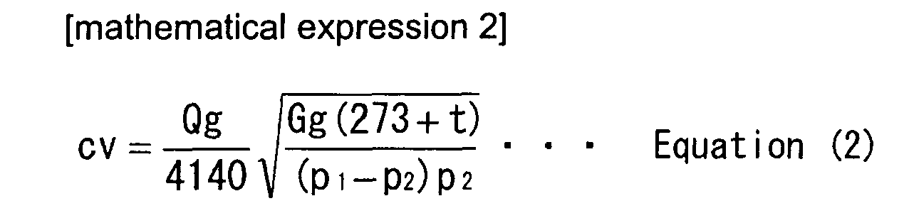
where Qg [m /h (standard state)] is the flow rate of the gas at the standard state (15°C, 760 mmHg abs), t [°C] is the gas temperature, Gg is a specific gravity of the gas (when air, Gg = 1), P1 [MPa abs] is the primary side absolute pressure and P2 [MPa abs] is the secondary side absolute pressure. - Furthermore, the gas flow rate Qg, and the like, are usually measured by using a Cv value measurement test device as shown in
Figure 8 , and the Cv value is calculated by Equation (2) using the result of the measurement. As shown byFigure 8 , N is a fluid under the test specimen (Nitrogen gas), B designates a pressure reducing valve, C designates a filter, D designates a mass flow meter, E designates a manometer, and F designates a test specimen valve (a valve to be tested). The secondary side of the test specimen valve F is open to the atmosphere. A test has been conducted under the conditions of a Nitrogen gas temperature (at room temperature of 20°C), with the primary side pressure = 0.01 MPa, the secondary side pressure = atmospheric pressure (open to the atmosphere), and the valve opening degree = 10 to 100% (arbitrarily set). The Cv value required for the metal diaphragm valve is approximately 0.55 to 0.8. In the case of a valve having a diameter of 9.52 mm φ, the Cv value is approximately 0.7 when the maximum bulge height Δh of themetal diaphragm 22 is 1.2mm (a full stroke ΔS = 1.0 mm). - With a conventional metal diaphragm valve of this type, there has been a problem that cracks are apt to be caused on a metal diaphragm. Specifically, the durability of the valve expressed by the number of continuous open/close operations of the metal diaphragm valve is normally approximately 1.5 to 2 million times when the valve has a fluid passage of 9.52 mm φ, and approximately 8 to 10 million times when the valve has a fluid passage of 6.35 mm φ. When the number of repetitions of the open/close operation exceeds the above stated durability number, normally damage is caused due to the repetitions of displacement of the
metal diaphragm 22, thus resulting in the need to replace the metal diaphragm valve more frequently. - This is particularly true with recently introduced semiconductor manufacturing facilities, which employ the ALD (Atomic Layer Deposition) method for processing because the number of repetitions of open/close operation of a diaphragm valve in the gas supply system is substantially increased. Accordingly, various durability difficulties are encountered in practical use of continuous open/close operations with a conventional metal diaphragm valve (in the case of a 9.52 mm
φ metal diaphragm 22 having an outside diameter of 26 mm φ, approximately 1.5 million times with a full stroke ΔS = 1.2 mm, and approximately 2.5 million times with a full stroke ΔS = 1.0 mm). - With this type of conventional diaphragm valve, there remains an unsolved problem that the Cv value is difficult to stabilize due to changes of flow rate characteristics over time, that is, the Cv value is easily affected by changes of the Cv value over time. Specifically, for a conventional metal diaphragm valve, as shown in
Figure 10 , deformation of thevalve seat 33 with time cannot be avoided due to the fact that a synthetic resin material (PFA) is used for thevalve seat 33; especially when temperature of fluids passing through the valve is high, the afore-mentioned deformation over time is apt to become bigger. For example, with a conventional valve of 9.52 mm φ, when the fluid temperature rises from 20°C to 150°C, thevalve seat 33 swells, while in the case where the travel volume (a lift stroke) of a stem is fixed constant, it is found that the flow rate of fluid decreases approximately by 18%. And, when open/close operations are conducted under conditions of high temperature, the flow rate at the time when the valve is fully open increases due to changes with time. As a result, for a metal diaphragm valve flow rate increases only for switching of full closing or full opening, and for a metal diaphragm valve for controlling both the flow rate and pressure, accurate control of the flow rate and pressure cannot be expected for the reason that the relationship between the degree of valve opening and the flow rate changes with time. - Reference is made to
JP 5-80858 - The present invention solves the above-mentioned problems with a conventional metal diaphragm valve, namely, (a) for semiconductor manufacturing facilities, and the like, which employ an Atomic Layer Deposition (ALD) method for treatment processing, due to the fact that the frequencies of open/close operations of the metal diaphragm valve is increased substantially, the conventional metal diaphragm valve, which has a durability of 1 to 2.5 million times expressed by the number of continuous open/close operations, needs to be changed with increased frequency and maintenance costs go up, and maintenance becomes troublesome, and (b) the shape of the valve seat changes over time, which causes fluctuations of the Cv value thus making flow characteristics of the valve unstable. Also, a primary object of the present invention is to provide a direct touch type metal diaphragm valve that makes it possible for durability of the valve, expressed by continuous open/close operations, to be remarkably improved without decreasing flow characteristics of the valve (that is, without substantial decrease of the Cv value). This object is achieved by means of employing a metal diaphragm valve having the same constitution as that of the conventional one, and that, at the same time, has a Cv value that is less affected by ageing because its flow characteristics are stable.
- Inventors of the present invention have focused attention on that the durability (the number of continuous open/close operations) of a metal diaphragm valve is closely related to the valve stroke ΔS, and that the valve stroke ΔS is directly related to the flow rate coefficient Cv (the Cv value). The inventors studied and examined the correlation of durability, valve stroke ΔS and flow rate coefficient Cv of various metal diaphragm valves by using the afore-mentioned Cv value measurement testing device shown in
Figure 8 . - Table 1 below,
Figure 6 ,Figure 7 and Table 2 and Table 3 below, andFigure 9 show one example study. Through various tests, it has been learned that, with a conventional metal diaphragm valve, an increase of the Cv value reaches a saturated state when the valve stroke ΔS exceeds a certain value. Thus, to obtain a prescribed Cv value, there is no need for the valve stroke ΔS to be made to be the same as the full stroke ΔS, which is equal to the maximum bulge height Δh of themetal diaphragm 22. Instead, a Cv value exceeding 0.55 to 0.7 may be achieved with a valve stroke ΔS having a height of approximately 55 to 70% of the maximum height Δh. - The present invention is based on the afore-mentioned findings. The present invention, as claimed in
Claim 1, is fundamentally constituted so that, for a direct touch type metal diaphragm valve made up of a body equipped with avalve seat 13 on the bottom face of aconcaved valve chamber 12 for communication to afluid inlet 10 and afluid outlet 11, ametal diaphragm 2 is provided above thevalve seat 13, and to hold hermeticity of thevalve chamber 12, is directly contacted with thevalve seat 13 by its center part moving up and down. Astem 8 is provided above themetal diaphragm 2 for free descent /ascent, which allows the center part of themetal diaphragm 2 to descend, and anactuator 9 is provided that allows thestem 8 to descend or ascend, and apress adaptor 3 is provided above the outer peripheral part of themetal diaphragm 2 to hold themetal diaphragm 2 hermetically between thepress adaptor 3 and the bottom face of the valve chamber and to control the descent of thestem 8 at the time of the valve being fully closed. The afore-mentionedmetal diaphragm 2 is made up of a laminated body comprising a plural number of thin stainless steel plates and thin Nickel · Cobalt alloy plate is formed in the shape of a round, reverse-dish with its center part bulged upward, and the 55 to 70% distance of the maximum bulge height Δh of the afore-mentionedmetal diaphragm 2 is regulated to be the maximum valve stroke ΔS of the valve. - The present invention, as claimed in
Claim 2 according toClaim 1, is made so that the Cv value of the valve at the time of maximum valve stroke ΔS is made to be 0.55 to 0.8. - The present invention, as claimed in
Claim 3 according toClaim 1 orClaim 2, is made so that themetal diaphragm 2 is made to have a bulge curvature that is 66 to 65 mm with an outer diameter of 15 mmφ, a bulge curvature that is 62 to 63 mm with an outer diameter of 18 to 20 mmφ, or a bulge curvature that is 59 to 61 mm with an outer diameter of 24 to 26mmφ. - The present invention, as claimed in
Claim 4 according toClaim 1, is made so that themetal diaphragm 2 is a round, laminated body made out of 3 pieces of thin stainless steel plate and 1 piece of thin Nickel Cobalt alloy plate, and its outer diameter is 24 to 26 mmφ, the maximum bulge height Δh is 1.2 to 1.3 mm and the maximum valve stroke ΔS is 0.65 to 0.8 mm. - The present invention, as claimed in
Claim 5 according toClaim 1 toClaim 4, is made so that thevalve seat 13 is made with PFA, astem 8 is provided with a valvestroke adjustment mechanism 16 so that the valve stroke ΔS is adjusted and fixed to a prescribed set value by the afore-mentioned valvestroke adjustment mechanism 16 after continuous open/close operations of the valve are performed over 3000 to 10000 times. - With the present invention, a direct touch type metal diaphragm valve is made so that the maximum bulge height Δh of the metal diaphragm is 55 to 70% of the size (distance) of the maximum bulge height Δh, which is the minimum requirement to obtain a desired flow rate coefficient Cv without making it the full stroke ΔS of a valve, thus allowing distortion volume and distortion stress applied to the metal diaphragm during open/close operations of a valve to be smaller, and at the same time, a prescribed flow rate coefficient (Cv value) as required is fully secured. As a result, it is possible that the feasible number of repetitions of continuous open/close operations, which indicates the durability of the metal diaphragm valve, is raised to approximately 20 to 30 times that of the conventional metal diaphragm valve.
- A stroke adjustment mechanism is provided according to the present invention, and approximately 3000 to 10000 continuous open/close operations are conducted before shipment of the valve in order to break-in the synthetic resin made valve seat in order to achieve its stabilization. As a result, the so-called changes with time of the valve seat are substantially reduced, thus the flow rate coefficient Cv (Cv value) is more stable.
-
-
Figure 1 is a cross sectional schematic view of a direct touch type metal diaphragm valve in accordance with the present invention in the case wherein the diaphragm valve is of the NC (normally closed) type. -
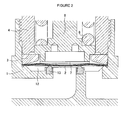
Figure 2 is an explanatory drawing showing a deformed condition of the metal diaphragm when the valve is closed with a valve stroke ΔS = 1.5 mm in accordance with the valve embodiment shown inFigure 1 . -
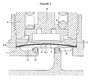
Figure 3 is an explanatory drawing showing a deformed condition of the metal diaphragm when the valve is open with a valve stroke ΔS = 1.5 mm, in accordance with the valve embodiment shown inFigure 1 . -
Figure 4 is an explanatory drawing showing a deformed condition of the metal diaphragm when the valve is closed with a valve stroke ΔS = 0.7 mm, in accordance with the valve embodiment shown inFigure 1 . -
Figure 5 is an explanatory drawing showing a deformed condition of the metal diaphragm when the valve is open with a valve stroke ΔS = 0.7 mm, in accordance with the valve embodiment shown inFigure 1 . -
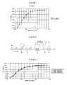
Figure 6 is a diagram showing the relationship between the valve stroke ΔS (valve lift) and the flow rate with a valve in accordance withFigure 1 . -
Figure 7 is a diagram showing the relationship between the valve stroke ΔS (valve lift) and the Cv value with a valve in accordance withFigure 1 . -
Figure 8 is a block system diagram of a Cv measurement testing device used with the present invention. -
Figure 9 is the illustration of the results tabulated in Table 2. -
Figure 10 is a cross sectional schematic diagram of a conventional direct touch type metal diaphragm valve. -
- A
- Driving fluid (air)
- Δh
- Maximum Bulge height of a bulging part
- ΔS
- Valve stroke (valve lift)
- G
- Space
- N
- Nitrogen gas source
- B
- Pressure reducing valve
- C
- Filter
- D
- Flow meter
- E
- Manometer
- F
- Valve to be tested
- P1
- Primary side pressure
- 1
- Body
- 2
- Metal diaphragm
- 3
- Press adaptor (SUS630)
- 4
- Bonnet
- 5
- Screw part
- 6
- Spring
- 7
- Diaphragm presser (polyimide)
- 8
- Stem
- 8a
- Brim portion
- 9
- Actuator
- 9a
- Supporting cylinder part
- 9b
- Screw
- 9c
- Piston
- 10
- Fluid inlet
- 11
- Fluid outlet
- 12
- Valve chamber
- 13
- Valve seat
- 14
- Driving shaft
- 15
- Stroke adjustment mechanism
- 15a
- Lock nut
- 16
- Electro-magnetic valve
- 17
- Proximity sensor
- The embodiment in accordance with the present invention is described as follows with reference to the drawings.
Figure 1 is a cross sectional schematic view of a direct touch type metal diaphragm valve (hereinafter called a "metal diaphragm valve") according to the present invention in the case wherein the metal diaphragm valve is made to be an NC (normally closed) type valve.
Figure 2 andFigure 3 are enlarged views to show deformed forms when the metal diaphragm shown inFigure 1 is closed and opened with a valve stroke Δ S = 1.5 mm. Furthermore,Figure 4 andFigure 5 are enlarged views showing deformed forms when the metal diaphragm shown inFigure 1 is closed and opened with a valve stroke ΔS = 0.7 mm. - As shown with
Figure 1, 1 designates a body, 2 designates a metal diaphragm, 3 designates a press adaptor, 4 designates a bonnet, 5 designates a screw part, 6 designates a spring, 7 designates a diaphragm presser, 8 designates a stem, 9 designates an actuator, 10 designates a fluid inlet, 11 designates a fluid outlet, 12 designates a valve chamber, 13 designates a valve seat, 14 designates a driving shaft, 15 designates a stroke adjustment mechanism, 16 designates an electro-magnetic valve, and 17 designates a proximity sensor. - The afore-mentioned
body 1 is made out of stainless steel in a near-cross shape and is provided with aconcave valve chamber 12 with an open top for communication to afluid inlet 10 and afluid outlet 11 on both sides of the chamber, wherein thefluid inlet 10 and thefluid outlet 11 open on an upper part of the body. A synthetic resin (PFA, PA, PI, PCTFE, and the like) madevalve seat 13 is fitted and fixed to the bottom face of thevalve chamber 12. In accordance with the present embodiment of the invention, thevalve seat 13 is fixed to a valve fitting groove by means of so-called cramp processing. - The afore-mentioned
metal diaphragm 2 is installed above thevalve seat 13, to maintain hermeticity of thevalve chamber 12, and moves to and away from thevalve seat 13 with its center part moving upward and downward. In accordance with the present embodiment, themetal diaphragm 2 is formed in a round, reverse-dish shape by bulging a center part of a thin metal plate (0.1 to 0.2 mm thick) made of special stainless steel (such trade names as Inconel, Spron), and the like, and a thin Nickel Cobalt alloy plate (0.1 to 0.2 mm thick) upward. By laminating 3 pieces of the reverse-shaped thin special stainless steel plate and 1 piece of a Nickel Cobalt alloy plate into intimate contact, themetal diaphragm 2 is formed in a reverse-dish shape. Themetal diaphragm 2, which has a peripheral part that is placed on the extruded part of an inner peripheral face of thevalve chamber 12, is thrust onto the extruded side of thebody 1 through the mediation of a stainless steel madepress adaptor 3 by means of the lower end of abonnet 4 that is inserted into thevalve chamber 12 and is screwed into ascrew part 5 of thebody 1, thus allowing themetal diaphragm 2 to be held and fixed hermetically. The Nickel · Cobalt alloy film is placed on the gas-contacting side of the metal diphragm. - More specifically, the
metal diaphragm 2 is formed to have an outer diameter of 26 mm, a curvature of the bulged part of 60 mm in the case wherein the valve is used for a valve with an inner diameter of a fluid passage of 9.52 mm φ. The maximum bulge height Δh of the afore-mentioned bulged part (Δh inFigure 3 described later) is 1.2 mm. As examples of ametal diaphragm 2 as implemented, there exist one metal diaphragm with an outer diameter of 20 mm and a curvature of 62.6 mm for a valve with an inner diameter of a fluid passage of 6.35 mm φ, and another metal diaphragm with an outer diameter of 15 mm and a curvature of 62.6 mm for a small sized valve with an inner diameter of a fluid passage of 6.35 mm φ, and the like. - The afore-mentioned
bonnet 4 is formed in a cylindrical shape and is inserted into thevalve chamber 12 of thebody 1, and is fixed to the side of thebody 1 by means that it is screwed into thescrew part 5 provided on the inner peripheral face of thevalve chamber 12. - The afore-mentioned
stem 8 is inserted into the lower end part of thebonnet 4 for free descending and ascending. A synthetic resin madediaphragm presser 7, which contacts with the upper face of the center part of ametal diaphragm 2, is provided on the lower end face of thestem 8. - More specifically,
stem 8 is installed in thebonnet 4 for free descending and ascending so that the polyimide madediaphragm presser 7 fixed on the lower end face contacts with themetal diaphragm 2, and is pressed down with the elastic force ofspring 6 through the mediation of adiaphragm presser 7 so that the center part of themetal diaphragm 2 can rest on thevalve seat 13. A drivingshaft 14 for anactuator 9, which operates the stem, is fixed on the upper end part of thestem 8 - There is provided a
brim part 8a on the lower part of the afore-mentionedstem 8. When the valve is fully closed (or the center part of ametal diaphragm 2 rests on the valve seat 13), excessive descent of thestem 8 is controlled due to thebrim part 8a, which touches the upper face of the afore-mentioned press adaptor. - The afore-mentioned
stroke adjustment mechanism 15 comprises alock nut 15a screwed to a supportingcylinder part 9a of theactuator 9 and fixed by screwing to the upper face of abonnet 4. A screw 9b for thelock nut 15a is provided on the outer peripheral face of the supportingcylinder part 9a, and the like. The height position of the supportingcylinder part 9a screwing into thebonnet 4 can be adjusted so that the size of the valve stroke ΔS is adjusted. - The afore-mentioned electro-
magnetic valve 16 is directly fixed to the upper face of theactuator 9 and controls the flow of a driving fluid (air) A supplied into theactuator 9. The reason why theactuator 9 is directly fixed to the electro-magnetic valve 16 is to raise responsivity of open/close operations of the valve by minimizing the space of the driving fluid passage as described later (shortening of open/close operation time). - The afore-mentioned
proximity sensor 17, which is for detecting changes of the valve stroke ΔS and the valve stroke ΔS itself at the time when the valve is operated for opening and closing, is formed on the upper face side of theactuator 9. The afore-mentioned stroke ΔS is detected by measuring the space ΔG with apiston 9c. - Next, the operating procedure of a metal diaphragm valve, in accordance with the present invention, is explained. A valve, as shown in
Figure 1 is constituted as a so-called NC (normally closed) type, thrusts themetal diaphragm 2 downward through the mediation ofstem 8 with elastic force of thespring 6 at all times, and the thin Nickel - Cobalt alloy plate of the down side face (a gas contacting face) of the metal diaphragm remains rested on thevalve seat 3. Thrust of thestem 8 is adjusted by thespring 6, and the descending volume ofstem 8 is regulated by thepress adaptor 3. - When driving air A is supplied to the
actuator 9, a drivingshaft 14 is raised upward by a valve stroke ΔS through mediation of thepiston 9c, thus allowing the center part of themetal diaphragm 2 to be restored to the shape that is bulged upward by its elastic force so that the valve is opened. The afore-mentioned valve stroke ΔS is adjusted to a prescribed value by means of thelock nut 15a of thestroke adjustment mechanism 15. Specifically, as described later, the valve stroke ΔS is set to 0.65 to 0.8 mm (preferably 0.7 mm) in the case wherein themetal diaphragm 2 has an outer diameter of 26 mm φ, a curvature of 60 mm, the maximum height of the bulged part Δh = 1.2 mm, 3 pieces of 0.15 mm thick special stainless steel plate and 1 piece of 0.15 mm thick Nickel · Cobalt alloy plate (which is hereinafter called "a metal diaphragm in the implementation example 1 ") when the metal diaphragm is used for a valve for a diameter of 9.52 mm φ. - Next, it is described how the valve stroke ΔS of the
metal diaphragm 2, in accordance with the present invention, is decided. - Referring to
Figure 2, Figure 2 is a partially enlarged view to show the closed state of the valve for which themetal diaphragm 2 in the afore-mentioned implementation example 1 is used.Figure 3 is a partially enlarged view to show the open state of the valve for which themetal diaphragm 2 in the afore-mentioned implementation example 1 is used. In accordance withFigure 2 andFigure 3 , the valve stroke ΔS is chosen to be 1.5 mm. Themetal diaphragm 2 is completely restored to its original shape due to the fact that the valve stroke ΔS is larger than the maximum height Δh = 1.2 mm of a bulged part of themetal diaphragm 2. -
Figure 4 andFigure 5 are partly enlarged views to show a closed state (Figure 4 ) and an open state (Figure 5 ) when the valve stroke ΔS is made to be 0.7 mm in accordance with the valve shown inFigure 1 , in which thediaphragm 2 in the implementation example 1 mentioned in paragraph [0041] is used. Themetal diaphragm 2 remains slightly deformed without being restored completely back to its original state, as shown inFigure 3 , even when the valve is closed. Specifically, when the valve stroke ΔS is made to be small, deformation volume of themetal diaphragm 2 becomes small; hence, distortion stress applied to themetal diaphragm 2 becomes relatively small. - Now, when comparing a valve stroke ΔS=1.5mm with a valve stroke ΔS=0.7mm, much difference is seen in the shape of a
metal diaphragm 2 as stated before, but it is learned that not much difference is seen in the space G between avalve seat 3 and the inner surface of ametal diaphragm 2. -
Figure 6 andFigure 7 show the results of a Cv value obtained by the afore-mentioned equation (2) after the flow rate was measured by using the afore-mentioned Cv value measurement test device, shown inFigure 8 , on the metal diaphragm shown inFigure 1 wherein themetal diaphragm 2 in the afore-mentioned implementation example 1 is used. Table 1 is a chart to show the lift, flow rate and Cv value corresponding to this test. The test was conducted under conditions of operating air pressure of 0.55 Mpa, and the projected height of the valve seat of 0.128 mm (the height after baking at 80°C). -
[Table 1] Lift(mm) Flow Rate (L/min) Cv Value 0.000 0.0 0.000 0.102 0.4 0.003 0.203 15.9 0.130 0.310 34.8 0.284 0.408 46.0 0.375 0.505 59.0 0.482 0.593 65.0 0.531 0.700 74.0 0.604 0.792 75.0 0.612 0.897 77.0 0.628 1.000 79.0 0.645 1.106 80.0 0.653 1.202 80.0 0.653 1.316 80.0 0.653 - As apparent from
Figure 6 andFigure 7 , it is learned that a Cv value of 0.55 to 0.6 required for the valve can be achieved with a valve stroke ΔS of approximately 0.65 to 0.8. In particular, by making the valve stroke ΔS to be 0.7 mm, a Cv value of 0.6 can be achieved. It is learned that there is no need for themetal diaphragm 2 to be deformed to the maximum extent possible by making the valve stroke to be 1.3 mm (the maximum value). - Table 2 shows the results of the same test on a valve having the same diaphragm specifications as those in Table 1 for the
metal diaphragm 2 in the implementation example 1 mentioned in paragraph [0041], only except that the diameter of the pipe passage connected to thefluid inlet 10 is 6.35 mm φ. For this test, 3 valves were manufactured for testing, No.1 valve with the projected height of thevalve seat 3 of 0.174 mm, No.2 valve of 0.176 mm and No.3 valve of 0.068 mm. In particular, with the No.3 valve, the valve's open/close operations were conducted over 10000 times in advance by striking the face of a valve seat for braking in the valve and the operating air pressure was made to be 0.55 Mpa (upper limit value). -
[Table 2] Lift (mm) Test Valve No.1 Test valve No.2 Test valve No,3 Flow rate Cv Value Flow rate Cv Value Flow rate Cv value 0.000 0.0 0.000 0.0 0.000 0.0 0.000 0.100 0.0 0.000 0.0 0.000 0.0 0.000 0.200 10.7 0.087 13.1 0.107 12.0 0.098 0.300 30.0 0.245 30.5 0.249 28.3 0.231 0.400 43.9 0.358 43.7 0.357 46.7 0.381 0.500 51.0 0.416 50.0 0.408 56.0 0.457 0.600 58.0 0.473 61.0 0.498 64.0 0.522 0.700 65.0 0.531 65.0 0.531 66.0 0.539 0.800 68.0 0.555 67.0 0.547 69.0 0.563 0.900 70.0 0.571 71.0 0.579 70.0 0.571 1.000 71.0 0.579 71.0 0.579 72.0 0.588 1.100 72.0 0.588 71.0 0.579 74.0 0.604 1.200 73.0 0.596 71.0 0.579 73.0 0.596 1.300 73.0 0.596 71.0 0.579 73.0 0.596 -
Figure 9 graphs the result of Table 2. It is learned that, similar to the case of the metal diaphragm in the implementation example 1, a required Cv value 0.5 to 0.6 can be obtained with a value stroke ΔS of approximately 0.65-0.7. - Table 3 and Table 4 show changes of the Cv value due to deterioration of the shape of the valve seat over time, and the data shown here illustrate the relationship between the number of open/close operations and Cv value when the valve seat was struck by conducting open/closed operations of the valve at high temperature of 200°C in advance. Table 3 shows the measurement result when the measurement of Cv value was conducted at high temperatures of 200°C, and Table 4 shows the measurement result when the measurement of Cv value was conducted at normal temperatures.
-
[Table 3] No.of Open/Close Operations(times) No. 1 No. 2 No. 3 0 0. 304 0.326 0.316 1000 0. 502 0.489 0.476 3000 0. 520 0. 507 0.491 5000 0.519 0.512 0.506 10000 0.529 0.529 0.51 20000 0.529(74%UP) 0.529(62.2%UP) 0.512(62%UP) -
[Table 4] (times) No. 1 No. 2 No. 3 0 0. 498 0. 506 0.498 20000 0.579(16%UP) 0.571(12.8%UP) 0.555(11.4%UP) - From the results shown in the above Table 3 and Table 4, it is apparent that changes of the shape of the
valve seat 13 cease after continuous open/close operations of the valve over approximately 10000 times in advance, wherein the Cv value goes up and becomes nearly saturated. - Table 5 shows the relationship between the stroke ΔS when continuous open/close operations, using a valve for which the
metal diaphragm 2 in the implementation example 1 mentioned in [0041] is used, and the number of open/close operations until the time when a metal diaphragm is ruptured (the endurable number of open/close operations), where velocity of open/close operations of a valve is 3 times per second to 4 times per second. -
[Table 5] Stroke ΔS mm Number of endurable open/close operations 1.2 mm or more Approx. 1.5 million times 1 mm Approx. 2.5 million times 0.7 mm Approx. 50 million times - As apparent from the above Table 5, with a direct touch type metal diaphragm valve for which a metal diaphragm having the maximum bulge height Δh of approximately 1.2 mm and the external diameter of 20 to 26mm φ is used, it is learned that the required Cv value is maintained, and at the same time the number of endurable open/close operations can be tremendously increased by means that the valve stroke ΔS is made to be the value of 55 to 70% of the maximum bulge height Δh.
- The present invention can be applied not only to semiconductor manufacturing facilities but also to chemical goods and pharmaceutical industries as well as foods processing industry, and the like.
Claims (5)
- A direct touch type metal diaphragm valve characterized by that, with a direct touch type metal diaphragm valve made up of a body equipped with a valve seat on the bottom face of a concave valve chamber for communication to a fluid inlet and a fluid outlet, a metal diaphragm provided above a valve seat, to hold hermeticity of a valve chamber, directly contacted with a valve seat by means of its center part moving upward and downward, and a stem provided above the metal diaphragm for free descent/ascent which allows the center part of the metal diaphragm to descend, an actuator which allows the stem to descend or ascend, and a press adaptor provided above the outer peripheral part to hold the metal diaphragm hermetically between the press adaptor and the bottom face of a valve chamber and to control the descent of the stem at the time of a valve being fully closed; the above-mentioned metal diaphragm made up of a laminated body comprising a plural number of thin stainless steel plate and thin Nickel · Cobalt alloy plate is formed in the shape of a round, reverse-dish with its center part bulged upward, and the 55~70% distance of the maximum bulge height Δh of the above mentioned metal diaphragm is regulated to be the maximum valve stroke ΔS of a valve.
- A direct touch type metal diaphragm valve as claimed in Claim 1, wherein a Cv value of a valve at the time of the maximum valve stroke ΔS is made to be 0.55∼0.8.
- A direct touch type metal diaphragm valve as claimed in Claim 1 or Claim 2, wherein a metal diaphragm is made to be that a bulge curvature is 66∼65mm with an outer diameter of 15mm φ, a bulge curvature is 62~63mm with an outer diameter of 18~20mm φ, or a bulge curvature is 59~61mm with an outer diameter of 24∼26mm φ.
- A direct touch type metal diaphragm valve as claimed in Claim 1, wherein a metal diaphragm is made to be a round laminated body made out of 3 pieces of thin stainless steel plate and 1 piece of thin Nickel. Cobalt alloy plate, and its outer diameter is 24~26mm φ, the maximum bulge height Δh is 1.2∼1.3mm and the maximum valve stroke ΔS is 0.65∼0.8mm.
- A direct touch type metal diaphragm valve as claimed in Claim 1 to Claim 4, wherein a valve seat is made with PFA, a stem is provided with a valve stroke adjustment mechanism so that a valve stroke ΔS is adjusted and fixed to a prescribed set value by using the afore-mentioned valve stroke adjustment mechanism after continuous open/close operations of a valve are performed over 3000 to 10000 times.
Applications Claiming Priority (2)
| Application Number | Priority Date | Filing Date | Title |
|---|---|---|---|
| JP2005250300A JP5054904B2 (en) | 2005-08-30 | 2005-08-30 | Direct touch type metal diaphragm valve |
| PCT/JP2006/309369 WO2007026448A1 (en) | 2005-08-30 | 2006-05-10 | Direct-touch type metal diaphragm valve |
Publications (1)
| Publication Number | Publication Date |
|---|---|
| EP1921358A1 true EP1921358A1 (en) | 2008-05-14 |
Family
ID=37808551
Family Applications (1)
| Application Number | Title | Priority Date | Filing Date |
|---|---|---|---|
| EP06746186A Withdrawn EP1921358A1 (en) | 2005-08-30 | 2006-05-10 | Direct-touch type metal diaphragm valve |
Country Status (8)
| Country | Link |
|---|---|
| US (1) | US8256744B2 (en) |
| EP (1) | EP1921358A1 (en) |
| JP (1) | JP5054904B2 (en) |
| KR (1) | KR100982705B1 (en) |
| CN (1) | CN101233350B (en) |
| IL (1) | IL187800A (en) |
| TW (1) | TW200717209A (en) |
| WO (1) | WO2007026448A1 (en) |
Cited By (2)
| Publication number | Priority date | Publication date | Assignee | Title |
|---|---|---|---|---|
| US20120097881A1 (en) * | 2010-10-25 | 2012-04-26 | Ckd Corporation | Valve seat structure of fluid control valve |
| WO2015079444A1 (en) | 2013-11-28 | 2015-06-04 | Ham-Let (Israel-Canada) Ltd. | Valve device for controlling and adjusting fluid passage |
Families Citing this family (75)
| Publication number | Priority date | Publication date | Assignee | Title |
|---|---|---|---|---|
| US8172197B2 (en) * | 2006-07-06 | 2012-05-08 | Mks Instruments, Inc. | Fast-acting pneumatic diaphragm valve |
| JP4971030B2 (en) * | 2007-05-21 | 2012-07-11 | シーケーディ株式会社 | Fluid control valve |
| US20100185049A1 (en) * | 2008-10-22 | 2010-07-22 | Allergan, Inc. | Dome and screw valves for remotely adjustable gastric banding systems |
| JP5613420B2 (en) * | 2010-02-05 | 2014-10-22 | 株式会社フジキン | Fluid controller |
| JP5565856B2 (en) | 2010-03-24 | 2014-08-06 | セイコーインスツル株式会社 | Diaphragm, diaphragm valve, and method for manufacturing diaphragm |
| JP5153898B2 (en) * | 2010-04-28 | 2013-02-27 | セントラル硝子株式会社 | Valve for filling container of halogen gas or halogen compound gas |
| WO2011163210A1 (en) * | 2010-06-22 | 2011-12-29 | Swagelok Company | Clamp ring for welded diaphragms |
| JP5597468B2 (en) * | 2010-07-27 | 2014-10-01 | 株式会社フジキン | Air operated valve |
| JP5546018B2 (en) * | 2011-03-11 | 2014-07-09 | Ckd株式会社 | Flow control valve |
| WO2013010269A1 (en) | 2011-07-15 | 2013-01-24 | Mécanique Analytique Inc. | Actuator |
| US9476516B2 (en) | 2011-07-15 | 2016-10-25 | Mecanique Analytique Inc. | Actuator |
| JP5331180B2 (en) * | 2011-09-22 | 2013-10-30 | 株式会社フジキン | Valve stroke adjustment method for direct touch type metal diaphragm valve |
| JP5985314B2 (en) * | 2012-09-07 | 2016-09-06 | 株式会社堀場エステック | Valve element and fluid control valve |
| US20140103240A1 (en) * | 2012-10-17 | 2014-04-17 | Swagelok Company | Actuator with dual drive |
| US9454158B2 (en) | 2013-03-15 | 2016-09-27 | Bhushan Somani | Real time diagnostics for flow controller systems and methods |
| JP6232224B2 (en) * | 2013-07-26 | 2017-11-15 | 株式会社フジキン | Diaphragm valve |
| KR101475846B1 (en) * | 2013-10-31 | 2014-12-24 | 아성플라스틱밸브(주) | Diaphragm adhere to seat and diaphragm valve with the same |
| CN106461096A (en) * | 2014-01-07 | 2017-02-22 | 桑杜科技有限公司 | flow control valve |
| JP6335685B2 (en) * | 2014-06-30 | 2018-05-30 | 株式会社フジキン | Diaphragm valve, fluid control apparatus, semiconductor manufacturing apparatus, and semiconductor manufacturing method |
| JP6491878B2 (en) | 2014-12-25 | 2019-03-27 | 株式会社フジキン | Fluid controller |
| JP6491877B2 (en) * | 2014-12-25 | 2019-03-27 | 株式会社フジキン | Fluid controller |
| JP6530929B2 (en) * | 2015-02-27 | 2019-06-12 | 株式会社フジキン | Fluid controller |
| TW201638510A (en) * | 2015-04-16 | 2016-11-01 | Bueno Technology Co Ltd | Self-closing gas filling valve |
| JP6630517B2 (en) * | 2015-08-28 | 2020-01-15 | 株式会社フジキン | valve |
| JP6666672B2 (en) * | 2015-08-28 | 2020-03-18 | 株式会社フジキン | valve |
| US10352470B2 (en) * | 2015-11-17 | 2019-07-16 | Ge Aviation Systems Llc | Control valve and air starting system |
| WO2017169052A1 (en) * | 2016-03-30 | 2017-10-05 | Ckd株式会社 | Operating electromagnetic valve mounting structure, and fluid control valve |
| JP6166855B1 (en) * | 2016-03-30 | 2017-07-19 | Ckd株式会社 | Solenoid valve mounting structure for operation and fluid control valve |
| WO2018013857A1 (en) | 2016-07-13 | 2018-01-18 | Rain Bird Corporation | Flow sensor |
| KR102312480B1 (en) | 2016-11-08 | 2021-10-14 | 가부시키가이샤 후지킨 | Valve device, flow control method using the same, and semiconductor manufacturing method |
| CN110023659B (en) | 2016-11-30 | 2021-01-29 | 株式会社富士金 | Valve device, flow rate control method using the valve device, and semiconductor manufacturing method |
| JP6968429B2 (en) | 2016-12-26 | 2021-11-17 | 株式会社フジキン | Piezoelectric driven valve and flow control device |
| JP6914044B2 (en) * | 2017-01-31 | 2021-08-04 | 株式会社キッツエスシーティー | Diaphragm valve |
| US10983538B2 (en) | 2017-02-27 | 2021-04-20 | Flow Devices And Systems Inc. | Systems and methods for flow sensor back pressure adjustment for mass flow controller |
| JP6929098B2 (en) * | 2017-03-30 | 2021-09-01 | 株式会社キッツエスシーティー | Metal diaphragm valve |
| JP7065531B2 (en) * | 2017-05-31 | 2022-05-12 | 株式会社フジキン | Valve device and fluid control device |
| JP7148990B2 (en) | 2017-07-04 | 2022-10-06 | 株式会社フジキン | Actuators, valves, and semiconductor manufacturing equipment |
| KR102239202B1 (en) | 2017-07-04 | 2021-04-09 | 가부시키가이샤 후지킨 | Actuators, valves, fluid supply systems and semiconductor manufacturing equipment |
| KR102254663B1 (en) | 2017-07-31 | 2021-05-21 | 가부시끼가이샤후지킨 | Gas supply system |
| JP6941507B2 (en) * | 2017-08-31 | 2021-09-29 | 株式会社キッツエスシーティー | Mounting structure of solenoid valve for actuator and valve with actuator |
| CN111133239A (en) | 2017-09-25 | 2020-05-08 | 株式会社富士金 | Valve device, flow rate adjustment method, fluid control device, flow rate control method, semiconductor manufacturing apparatus, and semiconductor manufacturing method |
| CN111164341A (en) | 2017-09-25 | 2020-05-15 | 株式会社富士金 | Valve device, adjustment information generation method, flow rate adjustment method, fluid control device, flow rate control method, semiconductor manufacturing apparatus, and semiconductor manufacturing method |
| JP6914159B2 (en) | 2017-09-26 | 2021-08-04 | 株式会社キッツエスシーティー | Diaphragm valve assembly method and its assembly structure and diaphragm valve |
| US10473494B2 (en) * | 2017-10-24 | 2019-11-12 | Rain Bird Corporation | Flow sensor |
| KR102304548B1 (en) | 2017-11-24 | 2021-09-27 | 가부시키가이샤 후지킨 | Valve device and control method using the same, fluid control device and semiconductor manufacturing device |
| KR102325938B1 (en) | 2017-11-29 | 2021-11-12 | 가부시키가이샤 후지킨 | Valve, valve abnormality diagnosis method, and computer-readable recording medium |
| JP7045839B2 (en) * | 2017-12-08 | 2022-04-01 | 株式会社キッツエスシーティー | Fluid control valve |
| US10877495B2 (en) * | 2018-03-08 | 2020-12-29 | Emerson Process Management Regulator Technologies, Inc. | Pressure loaded regulator with dual diaphragm and redundant seal |
| JPWO2019171604A1 (en) | 2018-03-09 | 2021-02-18 | 株式会社フジキン | Valve device |
| WO2019171593A1 (en) | 2018-03-09 | 2019-09-12 | 株式会社フジキン | Valve device |
| JP2019190633A (en) * | 2018-04-27 | 2019-10-31 | 株式会社フジキン | Fluid controller |
| JP2018132194A (en) * | 2018-05-01 | 2018-08-23 | 株式会社フジキン | Diaphragm valve, fluid control device, semiconductor control device, and semiconductor control method |
| WO2020026579A1 (en) * | 2018-07-31 | 2020-02-06 | 株式会社フジキン | Valve device |
| JP7207693B2 (en) * | 2018-08-31 | 2023-01-18 | 株式会社フジキン | Actuator and air operated valve with the same |
| US11662242B2 (en) | 2018-12-31 | 2023-05-30 | Rain Bird Corporation | Flow sensor gauge |
| JP7709183B2 (en) * | 2019-01-31 | 2025-07-16 | 株式会社フジキン | Manufacturing method of diaphragm valve |
| CN113423987A (en) * | 2019-01-31 | 2021-09-21 | 株式会社富士金 | Valve device, flow rate control method, fluid control device, semiconductor manufacturing method, and semiconductor manufacturing device |
| KR102542263B1 (en) | 2019-01-31 | 2023-06-13 | 가부시키가이샤 후지킨 | Valve device, flow control method using this valve device, fluid control device, semiconductor manufacturing method, and semiconductor manufacturing device |
| WO2020171018A1 (en) * | 2019-02-19 | 2020-08-27 | 株式会社フジキン | Valve |
| US20220186844A1 (en) * | 2019-03-29 | 2022-06-16 | Fujikin Incorporated | Diaphragm and diaphragm valve |
| JP7253786B2 (en) * | 2019-05-27 | 2023-04-07 | 株式会社不二工機 | valve device |
| IL268254B2 (en) * | 2019-07-24 | 2024-10-01 | Ham Let Israel Canada Ltd | Flow control accessory |
| DE102019008017A1 (en) * | 2019-11-19 | 2021-05-20 | Vat Holding Ag | Gas inlet valve for vacuum process chambers |
| KR102614981B1 (en) * | 2019-12-06 | 2023-12-19 | 주식회사 유니락 | Quick open valve |
| JP7407616B2 (en) * | 2020-02-21 | 2024-01-04 | 株式会社キッツエスシーティー | How to replace a diaphragm valve and its valve seat |
| US20230136494A1 (en) * | 2020-03-30 | 2023-05-04 | Fujikin Incorporated | Valve system, output monitoring method and output adjusting method for diaphragm valve, and semiconductor manufacturing apparatus |
| CN111623141B (en) * | 2020-06-11 | 2022-04-26 | 江苏阀邦半导体材料科技有限公司 | Metal-to-metal direct sealing structure applied to semiconductor valve and treatment process |
| DE102020123249A1 (en) * | 2020-09-07 | 2022-03-10 | Knorr-Bremse Systeme für Nutzfahrzeuge GmbH | Plate armature damping device for a tilting armature valve, plate armature and tilting armature valve with a plate armature damping device |
| WO2022101013A1 (en) * | 2020-11-13 | 2022-05-19 | Asco Sas | Valve system |
| CN112503206B (en) * | 2020-12-07 | 2025-06-20 | 余姚市启华塑料制品有限公司 | A vacuum-free valve |
| WO2023188822A1 (en) * | 2022-03-30 | 2023-10-05 | 株式会社フジキン | Valve device |
| US12443208B2 (en) | 2023-02-08 | 2025-10-14 | Rain Bird Corporation | Control zone devices, systems and methods |
| KR20250013108A (en) * | 2023-07-18 | 2025-01-31 | 씨케이디 가부시키 가이샤 | Fluid control valve |
| US12498049B2 (en) | 2024-03-29 | 2025-12-16 | Rain Bird Corporation | Zone control devices, systems and methods |
| KR102796231B1 (en) * | 2024-12-31 | 2025-04-17 | 주식회사 토르 | diaphragm gas valve device |
Family Cites Families (21)
| Publication number | Priority date | Publication date | Assignee | Title |
|---|---|---|---|---|
| US3349795A (en) * | 1964-04-22 | 1967-10-31 | Ngk Insulators Ltd | Diaphragm valve including a snap ring connection |
| US4684106A (en) * | 1983-04-05 | 1987-08-04 | Nupro Company | Valve |
| DE3512393A1 (en) * | 1985-04-17 | 1986-10-09 | KIM Production Ltd., Haifa Bay | DIAPHRAGM VALVE |
| JPS63115970A (en) * | 1986-10-31 | 1988-05-20 | Motoyama Seisakusho:Kk | Diaphragm valve |
| US5009778A (en) * | 1989-02-27 | 1991-04-23 | Hewlett-Packard Company | Axially-driven valve controlled fluid trapping assembly |
| JP3006913B2 (en) * | 1991-05-09 | 2000-02-07 | 清原 まさ子 | Fluid controller |
| JP2927582B2 (en) * | 1991-08-26 | 1999-07-28 | 清原 まさ子 | Controller |
| US5295662A (en) * | 1991-08-26 | 1994-03-22 | Masako Kiyohara | Fluid flow-controller with improved diaphragm |
| US5335691A (en) * | 1992-05-26 | 1994-08-09 | Nupro Company | High pressure diaphragm valve |
| US5413311A (en) * | 1994-03-01 | 1995-05-09 | Tescom Corporation | Gas valve |
| JPH07317925A (en) * | 1994-05-27 | 1995-12-08 | Hitachi Metals Ltd | Diaphragm seal valve and its metal diaphragm |
| JPH08105554A (en) * | 1994-10-03 | 1996-04-23 | Hitachi Metals Ltd | Metal diaphragm valve |
| US5851004A (en) * | 1996-10-16 | 1998-12-22 | Parker-Hannifin Corporation | High pressure actuated metal seated diaphragm valve |
| US5730423A (en) * | 1996-10-16 | 1998-03-24 | Parker-Hannifin Corporation | All metal diaphragm valve |
| JPH10148275A (en) * | 1997-11-12 | 1998-06-02 | Ckd Corp | Air operated valve |
| JP2001289336A (en) * | 2000-04-03 | 2001-10-19 | Denso Corp | Switchgear with flow adjustment function |
| TW441734U (en) * | 2000-07-27 | 2001-06-16 | Ind Tech Res Inst | Switch mechanism of gas control module |
| US6685164B1 (en) * | 2000-09-11 | 2004-02-03 | Hamai Industries Limited | Control valve and diaphragm for use in the control valve |
| US20030042459A1 (en) | 2001-08-29 | 2003-03-06 | Gregoire Roger J. | Unitary diaphragm and seat assembly |
| CN2537864Y (en) * | 2002-04-04 | 2003-02-26 | 扬中新亚自控工程有限公司 | Cut-off diaphragm valve |
| US7243903B2 (en) * | 2005-06-22 | 2007-07-17 | Wincek Christopher P | Valve diaphragm with a compression restraining ring, and valve including same |
-
2005
- 2005-08-30 JP JP2005250300A patent/JP5054904B2/en not_active Expired - Fee Related
-
2006
- 2006-05-10 WO PCT/JP2006/309369 patent/WO2007026448A1/en not_active Ceased
- 2006-05-10 EP EP06746186A patent/EP1921358A1/en not_active Withdrawn
- 2006-05-10 US US11/914,517 patent/US8256744B2/en active Active
- 2006-05-10 KR KR1020077029374A patent/KR100982705B1/en not_active Expired - Lifetime
- 2006-05-10 CN CN2006800280294A patent/CN101233350B/en not_active Expired - Fee Related
- 2006-05-18 TW TW095117704A patent/TW200717209A/en not_active IP Right Cessation
-
2007
- 2007-12-02 IL IL187800A patent/IL187800A/en active IP Right Grant
Non-Patent Citations (1)
| Title |
|---|
| See references of WO2007026448A1 * |
Cited By (4)
| Publication number | Priority date | Publication date | Assignee | Title |
|---|---|---|---|---|
| US20120097881A1 (en) * | 2010-10-25 | 2012-04-26 | Ckd Corporation | Valve seat structure of fluid control valve |
| US8960644B2 (en) * | 2010-10-25 | 2015-02-24 | Ckd Corporation | Valve seat structure of fluid control valve |
| WO2015079444A1 (en) | 2013-11-28 | 2015-06-04 | Ham-Let (Israel-Canada) Ltd. | Valve device for controlling and adjusting fluid passage |
| EP3074672A4 (en) * | 2013-11-28 | 2017-07-05 | Ham-Let (Israel-Canada) Ltd. | Valve device for controlling and adjusting fluid passage |
Also Published As
| Publication number | Publication date |
|---|---|
| US8256744B2 (en) | 2012-09-04 |
| KR20080017038A (en) | 2008-02-25 |
| WO2007026448A1 (en) | 2007-03-08 |
| JP5054904B2 (en) | 2012-10-24 |
| TW200717209A (en) | 2007-05-01 |
| IL187800A (en) | 2014-05-28 |
| KR100982705B1 (en) | 2010-09-17 |
| JP2007064333A (en) | 2007-03-15 |
| IL187800A0 (en) | 2008-08-07 |
| CN101233350B (en) | 2010-12-29 |
| CN101233350A (en) | 2008-07-30 |
| US20100090151A1 (en) | 2010-04-15 |
| TWI320519B (en) | 2010-02-11 |
Similar Documents
| Publication | Publication Date | Title |
|---|---|---|
| US8256744B2 (en) | Direct touch type metal diaphragm valve | |
| JP5331180B2 (en) | Valve stroke adjustment method for direct touch type metal diaphragm valve | |
| KR101001194B1 (en) | Normally Open Piezoelectric Element-Driven Metal Diaphragm Control Valve | |
| JP4933936B2 (en) | Piezoelectric drive valve | |
| TWI795473B (en) | Fluid control valve | |
| US8960644B2 (en) | Valve seat structure of fluid control valve | |
| US9746102B2 (en) | Fluid control valve | |
| US7862002B2 (en) | Vacuum valve | |
| JP4298476B2 (en) | Fluid control device | |
| US10125876B2 (en) | Diaphragm valve, fluid control device, semiconductor manufacturing apparatus, and semiconductor manufacturing method | |
| WO2016035262A1 (en) | Piezoelectric element-driven valve and flow-rate control device including piezoelectric element-driven valve | |
| TW201606218A (en) | Diaphragm valve, fluid control device, semiconductor manufacturing device, and semiconductor manufacturing method | |
| JP4951091B2 (en) | Piezoelectric element driven metal diaphragm type control valve | |
| JPH0771628A (en) | All metal diaphragm valve | |
| JP2006336701A (en) | Flow control valve | |
| JP7709183B2 (en) | Manufacturing method of diaphragm valve | |
| JP2587982B2 (en) | Piezo drive valve | |
| JP7166599B2 (en) | Diaphragm valves and flow controllers | |
| TW202225892A (en) | pressure sensor |
Legal Events
| Date | Code | Title | Description |
|---|---|---|---|
| PUAI | Public reference made under article 153(3) epc to a published international application that has entered the european phase |
Free format text: ORIGINAL CODE: 0009012 |
|
| 17P | Request for examination filed |
Effective date: 20071114 |
|
| AK | Designated contracting states |
Kind code of ref document: A1 Designated state(s): AT BE BG CH CY CZ DE DK EE ES FI FR GB GR HU IE IS IT LI LT LU LV MC NL PL PT RO SE SI SK TR |
|
| STAA | Information on the status of an ep patent application or granted ep patent |
Free format text: STATUS: THE APPLICATION HAS BEEN WITHDRAWN |
|
| 18W | Application withdrawn |
Effective date: 20090318 |