EP1921325A1 - Turbo-propeller comprising an assembly of blades with adjustable orientation. - Google Patents
Turbo-propeller comprising an assembly of blades with adjustable orientation. Download PDFInfo
- Publication number
- EP1921325A1 EP1921325A1 EP07120360A EP07120360A EP1921325A1 EP 1921325 A1 EP1921325 A1 EP 1921325A1 EP 07120360 A EP07120360 A EP 07120360A EP 07120360 A EP07120360 A EP 07120360A EP 1921325 A1 EP1921325 A1 EP 1921325A1
- Authority
- EP
- European Patent Office
- Prior art keywords
- blades
- annular
- actuating member
- engine according
- rotating
- Prior art date
- Legal status (The legal status is an assumption and is not a legal conclusion. Google has not performed a legal analysis and makes no representation as to the accuracy of the status listed.)
- Granted
Links
- 230000000712 assembly Effects 0.000 abstract 3
- 238000000429 assembly Methods 0.000 abstract 3
- 239000012530 fluid Substances 0.000 description 3
- 241000940835 Pales Species 0.000 description 1
- 206010033546 Pallor Diseases 0.000 description 1
- 238000002485 combustion reaction Methods 0.000 description 1
- 230000001627 detrimental effect Effects 0.000 description 1
- 238000006073 displacement reaction Methods 0.000 description 1
- 238000012423 maintenance Methods 0.000 description 1
- 230000007246 mechanism Effects 0.000 description 1
- 238000007789 sealing Methods 0.000 description 1
Images

Classifications
-
- F—MECHANICAL ENGINEERING; LIGHTING; HEATING; WEAPONS; BLASTING
- F04—POSITIVE - DISPLACEMENT MACHINES FOR LIQUIDS; PUMPS FOR LIQUIDS OR ELASTIC FLUIDS
- F04D—NON-POSITIVE-DISPLACEMENT PUMPS
- F04D29/00—Details, component parts, or accessories
- F04D29/26—Rotors specially for elastic fluids
- F04D29/32—Rotors specially for elastic fluids for axial flow pumps
- F04D29/34—Blade mountings
- F04D29/36—Blade mountings adjustable
- F04D29/362—Blade mountings adjustable during rotation
-
- B—PERFORMING OPERATIONS; TRANSPORTING
- B64—AIRCRAFT; AVIATION; COSMONAUTICS
- B64C—AEROPLANES; HELICOPTERS
- B64C11/00—Propellers, e.g. of ducted type; Features common to propellers and rotors for rotorcraft
- B64C11/30—Blade pitch-changing mechanisms
- B64C11/32—Blade pitch-changing mechanisms mechanical
-
- F—MECHANICAL ENGINEERING; LIGHTING; HEATING; WEAPONS; BLASTING
- F01—MACHINES OR ENGINES IN GENERAL; ENGINE PLANTS IN GENERAL; STEAM ENGINES
- F01D—NON-POSITIVE DISPLACEMENT MACHINES OR ENGINES, e.g. STEAM TURBINES
- F01D7/00—Rotors with blades adjustable in operation; Control thereof
-
- F—MECHANICAL ENGINEERING; LIGHTING; HEATING; WEAPONS; BLASTING
- F02—COMBUSTION ENGINES; HOT-GAS OR COMBUSTION-PRODUCT ENGINE PLANTS
- F02C—GAS-TURBINE PLANTS; AIR INTAKES FOR JET-PROPULSION PLANTS; CONTROLLING FUEL SUPPLY IN AIR-BREATHING JET-PROPULSION PLANTS
- F02C6/00—Plural gas-turbine plants; Combinations of gas-turbine plants with other apparatus; Adaptations of gas- turbine plants for special use
- F02C6/20—Adaptations of gas-turbine plants for driving vehicles
- F02C6/206—Adaptations of gas-turbine plants for driving vehicles the vehicles being airscrew driven
-
- F—MECHANICAL ENGINEERING; LIGHTING; HEATING; WEAPONS; BLASTING
- F04—POSITIVE - DISPLACEMENT MACHINES FOR LIQUIDS; PUMPS FOR LIQUIDS OR ELASTIC FLUIDS
- F04D—NON-POSITIVE-DISPLACEMENT PUMPS
- F04D29/00—Details, component parts, or accessories
- F04D29/26—Rotors specially for elastic fluids
- F04D29/32—Rotors specially for elastic fluids for axial flow pumps
- F04D29/321—Rotors specially for elastic fluids for axial flow pumps for axial flow compressors
- F04D29/322—Blade mountings
- F04D29/323—Blade mountings adjustable
-
- Y—GENERAL TAGGING OF NEW TECHNOLOGICAL DEVELOPMENTS; GENERAL TAGGING OF CROSS-SECTIONAL TECHNOLOGIES SPANNING OVER SEVERAL SECTIONS OF THE IPC; TECHNICAL SUBJECTS COVERED BY FORMER USPC CROSS-REFERENCE ART COLLECTIONS [XRACs] AND DIGESTS
- Y02—TECHNOLOGIES OR APPLICATIONS FOR MITIGATION OR ADAPTATION AGAINST CLIMATE CHANGE
- Y02T—CLIMATE CHANGE MITIGATION TECHNOLOGIES RELATED TO TRANSPORTATION
- Y02T50/00—Aeronautics or air transport
- Y02T50/60—Efficient propulsion technologies, e.g. for aircraft
Definitions
- the invention relates to a turboprop comprising at least one set of controllable, controlled-pitch blades, the adjustable blade orientation constituting one of the parameters for managing the thrust of the turboprop.
- the invention relates more particularly to the orientation control of these blades.
- a twin-propeller turboprop comprising a turbine with two counter-rotating rotors respectively driving two sets of blades with adjustable orientation.
- the invention applies in particular to this type of aircraft turboprop.
- various blade control mechanisms are known.
- a known system comprises a conventional cylinder, arranged axially in the interior space in the center of the annular-ring turbine. Mechanical links transmit the movement of the cylinder rod radially to the adjustable blade.
- the invention aims to overcome all these disadvantages.
- the invention relates to a turboprop comprising at least one set of controllably adjustable blades, rotatably connected to a rotating casing mechanically connected to a turbine rotor, characterized in that each blade of said assembly is coupled, for the adjustment of its orientation, to an actuating member of an annular jack carried by said rotating casing, said jack being common to the blades of said assembly.
- annular jack located outside, at the base and in the immediate vicinity of all the blades it has the function of maneuvering, is much lighter and easier to maintain.
- the cylinder is accessible because located outside the turboprop, more particularly fixed on the rotating housing.
- annular piston The surface of the annular piston is large, which allows a control of the orientation of the blades under much lower pressures. Finally, there can be an annular jack for each set of blades, which provides an additional degree of freedom to manage the thrust of the turboprop.
- said annular cylinder comprises a body with two coaxial cylindrical walls and two annular end walls.
- the body houses an annular piston movable between the two end walls. This piston is integral with the aforementioned actuating member.
- said actuating member comprises a coaxial cylindrical tubular element fixed to the piston and passing through with an airtight sliding an annular opening made in one of the end walls of the jack.
- said actuating member comprises a plurality of rods attached to the piston, each passing with a leaktight sliding a cylindrical opening made in an annular end wall of the jack.
- Each blade is pivotally mounted on said rotating casing.
- the blade pivots about an axis perpendicular to the axis of rotation of the turbine and comprises at its base, a maneuvering arm articulated by its end to said actuator member of the jack.
- the invention advantageously relates to a turboprop engine according to the preceding definition, characterized in that it comprises a turbine with two counter-rotating rotors and two sets of blades with adjustable orientation, integral in rotation with two rotating housings respectively connected to said rotor, each set being actuated by an annular cylinder carried by the corresponding rotating casing.
- a turboprop 11 having, according to the example, two sets 13a, 13b of blades 14 adjustable orientation.
- the blades 14 of each set 13a, 13b are mounted on a rotating casing 16a, 16b in the form of an annular platform, itself rotatably mounted on the surface of a fixed casing 18.
- the blades 14 of each set are regularly spaced, circumferentially and oriented generally radially on the surface of the rotating housing.
- the fixed housing and the rotating housings have a common axis X.
- the fixed housing 18 houses a combustion chamber and a turbine 20 with two counter-rotating rotors 22a, 22b.
- Each rotor carries and drives in rotation one of the rotating casings 16a, 16b on which is mounted a set 13a, 13b of said adjustable-adjustable blades.
- Such a set of blades is controlled for adjusting the orientation of said blades, in order to manage the thrust of the turboprop.
- the invention relates primarily to the means for controlling the orientation of the blades or each set.
- each blade 14 of such an assembly 13a or 13b is coupled, for the adjustment of its orientation, to an actuating member 25 of an annular jack 27a, 27b carried by said corresponding rotating casing 16a, 16b. .
- This jack is common to the blades of said set.
- each blade 14 of a set 13a, 13b is pivotally mounted on the rotating casing 27a, 27b corresponding, about an axis perpendicular to the axis of rotation X of the turbine and comprises at its base a maneuvering arm 30 completed by a ball joint 31. This ball is articulated to the actuating member 25 of the cylinder 27a or 27b.
- the annular cylinder 27a or 27b comprises a body with two cylindrical cylindrical walls 32, 33 coaxial and two annular end walls 34, 35.
- This body houses an annular piston 38 movable between the two end walls.
- the piston is integral with the actuating member 25.
- the actuating member 25 comprises a cylindrical tubular element 40 coaxial, fixed at one end to the piston 38 and through with tight sliding an annular opening 44 formed in the end wall 35 of the jack. This end wall 35 is close to the blades and the tubular element 40 is coupled to all the ball joints 31 of all the actuating arms 30 of the blades 14.
- said actuating member 25 comprises at its end a coaxial annular groove 50 housing receptacles 52. These receptacles 52 can slide in the groove 50, so as to allow any necessary relative movement between the finger 30 and the groove 50.
- Each receptacle has a spherical inner surface.
- the ball joints 31 articulate in corresponding receptacles 52. Consequently, a rectilinear displacement of the actuating member results in a uniform and simultaneous change of orientation of all the blades 14 of said assembly 13a or 13b.
- the two chambers of the cylinder separated by the piston are supplied with actuating fluid by two conduits 54, 55 passing through the corresponding rotor of the turbine and which join the stator of this turbine in the vicinity of the axis of the turboprop where chambers are arranged.
- the operating fluid is, according to the example, oil.
- the rotating casing 16a of the set of blades located at the front of the turboprop is carried by the rotor 22a having an outer casing and blades 56 directed radially inwards.
- the other rotating casing 16b is integral with the other rotor 22b comprising an inner casing and carrying blades 57 directed radially outwards.
- the turbine with two counter-rotating rotors is associated with the two sets of blades with adjustable orientation integral in rotation of the two rotating housings offset axially and respectively related to the rotors.
- Each set of blades is actuated by a ring cylinder 27a, 27b own, carried by the corresponding rotating casing 16a, 16b.
- the actuating member comprises a plurality of rods 59 attached to the piston 38.
- Each rod passes through with sealing a cylindrical opening 60 formed in the annular end wall 35 above.
- the stems are regularly distributed circumferentially. They can be connected to a coaxial annular groove of the same type as that of FIG. 2. It can also be envisaged that the number of rods is equal to the number of blades and that each rod 59 terminates in a receptacle in which the ball of one of the blades.
Abstract
Description
L'invention se rapporte à un turbopropulseur comportant au moins un ensemble de pales à orientation réglable, commandé, l'orientation réglable des pales constituant l'un des paramètres permettant de gérer la poussée du turbopropulseur. L'invention concerne plus particulièrement la commande d'orientation de ces pales.The invention relates to a turboprop comprising at least one set of controllable, controlled-pitch blades, the adjustable blade orientation constituting one of the parameters for managing the thrust of the turboprop. The invention relates more particularly to the orientation control of these blades.
On connaît, par exemple du brevet
Ces éléments de liaison sont complexes, encombrants, lourds et coûteux. De plus, les efforts à transmettre sont importants, ce qui nécessite des pressions d'actionnement élevées pour le vérin, compte tenu de la surface nécessairement limitée du piston de ce vérin. Cette pression de commande élevée est préjudiciable à la longévité du vérin. Si les deux ensembles de pales sont à orientation réglable, le vérin est généralement commun aux deux ensembles.These connecting elements are complex, bulky, heavy and expensive. In addition, the forces to be transmitted are important, which requires high actuation pressures for the cylinder, given the necessarily limited area of the piston of the cylinder. This high control pressure is detrimental to the longevity of the cylinder. If both sets of blades are adjustable in orientation, the jack is generally common to both sets.
La maintenance est compliquée car les éléments vitaux sont situés à l'intérieur du carter et plus particulièrement, pour certains, à l'intérieur de la turbine. On ne peut les changer sans avoir à démonter la turbine.Maintenance is complicated because the vital elements are located inside the housing and more particularly, for some, inside the turbine. They can not be changed without dismantling the turbine.
L'invention vise à surmonter tous ces inconvénients.The invention aims to overcome all these disadvantages.
Plus particulièrement, l'invention concerne un turbopropulseur comportant au moins un ensemble de pales à orientation réglable, commandé, solidaire en rotation d'un carter tournant mécaniquement lié à un rotor de turbine, caractérisé en ce que chaque pale dudit ensemble est couplée, pour le réglage de son orientation, à un organe d'actionnement d'un vérin annulaire porté par ledit carter tournant, ledit vérin étant commun aux pales dudit ensemble.More particularly, the invention relates to a turboprop comprising at least one set of controllably adjustable blades, rotatably connected to a rotating casing mechanically connected to a turbine rotor, characterized in that each blade of said assembly is coupled, for the adjustment of its orientation, to an actuating member of an annular jack carried by said rotating casing, said jack being common to the blades of said assembly.
Il résulte de la définition qui précède que le vérin annulaire situé à l'extérieur, à la base et à proximité immédiate de l'ensemble des pales qu'il a pour fonction de manoeuvrer, est beaucoup plus léger et facile à entretenir. Le vérin est accessible car situé à l'extérieur du turbopropulseur, plus particulièrement fixé sur le carter tournant.It follows from the above definition that the annular jack located outside, at the base and in the immediate vicinity of all the blades it has the function of maneuvering, is much lighter and easier to maintain. The cylinder is accessible because located outside the turboprop, more particularly fixed on the rotating housing.
La surface du piston annulaire est importante, ce qui permet une commande de l'orientation des pales sous des pressions beaucoup plus faibles. Enfin, on peut prévoir un vérin annulaire pour chaque ensemble de pales, ce qui procure un degré de liberté supplémentaire pour gérer la poussée du turbopropulseur.The surface of the annular piston is large, which allows a control of the orientation of the blades under much lower pressures. Finally, there can be an annular jack for each set of blades, which provides an additional degree of freedom to manage the thrust of the turboprop.
Selon un mode de réalisation possible, ledit vérin annulaire comporte un corps à deux parois cylindriques coaxiales et deux parois d'extrémités annulaires. Le corps abrite un piston annulaire mobile entre les deux parois d'extrémités. Ce piston est solidaire de l'organe d'actionnement précité.According to a possible embodiment, said annular cylinder comprises a body with two coaxial cylindrical walls and two annular end walls. The body houses an annular piston movable between the two end walls. This piston is integral with the aforementioned actuating member.
Selon une possibilité, ledit organe d'actionnement comporte un élément tubulaire cylindrique coaxial fixé au piston et traversant avec un coulissement étanche une ouverture annulaire pratiquée dans l'une des parois d'extrémités du vérin.According to one possibility, said actuating member comprises a coaxial cylindrical tubular element fixed to the piston and passing through with an airtight sliding an annular opening made in one of the end walls of the jack.
Selon une autre possibilité, ledit organe d'actionnement comporte une pluralité de tiges fixées au piston, chacune traversant avec un coulissement étanche une ouverture cylindrique pratiquée dans une paroi d'extrémité annulaire du vérin.According to another possibility, said actuating member comprises a plurality of rods attached to the piston, each passing with a leaktight sliding a cylindrical opening made in an annular end wall of the jack.
Chaque pale est montée pivotante sur ledit carter tournant. La pale pivote autour d'un axe perpendiculaire à l'axe de rotation de la turbine et comporte à sa base, un bras de manoeuvre articulé par son extrémité audit organe d'actionnement du vérin.Each blade is pivotally mounted on said rotating casing. The blade pivots about an axis perpendicular to the axis of rotation of the turbine and comprises at its base, a maneuvering arm articulated by its end to said actuator member of the jack.
L'invention concerne avantageusement un turbopropulseur selon la définition qui précède, caractérisé en ce qu'il comporte une turbine à deux rotors contrarotatifs et deux ensembles de pales à orientation réglable, solidaires en rotation de deux carters tournants respectivement liés auxdits rotor, chaque ensemble étant actionné par un vérin annulaire porté par le carter tournant correspondant.The invention advantageously relates to a turboprop engine according to the preceding definition, characterized in that it comprises a turbine with two counter-rotating rotors and two sets of blades with adjustable orientation, integral in rotation with two rotating housings respectively connected to said rotor, each set being actuated by an annular cylinder carried by the corresponding rotating casing.
L'invention sera mieux comprise et d'autres avantages de celle-ci apparaîtront plus clairement à la lumière de la description qui va suivre d'un turbopropulseur conforme à son principe, donnée uniquement à titre d'exemples et faite en référence aux dessins annexés, sur lesquels :
- la figure 1 est une vue générale en perspective du turbopropulseur conforme à l'invention ;
- la figure 2 est une vue schématique partielle en coupe du turbopropulseur ;
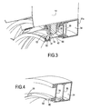
- la figure 3 est une vue de détail, en perspective et en coupe des moyens de commande des pales ; et
- la figure 4 est une vue de détail illustrant une variante du vérin.
- Figure 1 is a general perspective view of the turboprop according to the invention;
- Figure 2 is a partial schematic sectional view of the turboprop;
- Figure 3 is a detail view, in perspective and in section of the blade control means; and
- Figure 4 is a detail view illustrating a variant of the cylinder.
Sur les dessins, on a représenté un turbopropulseur 11 comportant, selon l'exemple, deux ensembles 13a, 13b de pales 14 à orientation réglable. Les pales 14 de chaque ensemble 13a, 13b sont montées sur un carter tournant 16a, 16b en forme de plateforme annulaire, lui-même monté en rotation à la surface d'un carter fixe 18. Les pales 14 de chaque ensemble sont régulièrement espacées, circonférentiellement et orientées globalement radialement, à la surface du carter tournant. Le carter fixe et les carters tournants ont un axe commun X. Le carter fixe 18 abrite une chambre de combustion et une turbine 20 à deux rotors contrarotatifs 22a, 22b. Chaque rotor porte et entraîne en rotation l'un des carters tournants 16a, 16b sur lequel est monté un ensemble 13a, 13b de pales à orientation réglable précitée. Un tel ensemble de pales est commandé pour le réglage de l'orientation desdites pales, en vue de gérer la poussée du turbopropulseur. La structure décrite jusqu'à présent est comparable, fonctionnellement, à celle qui est décrite dans le brevet
L'invention porte principalement sur les moyens de commande d'orientation des pales du ou chaque ensemble.The invention relates primarily to the means for controlling the orientation of the blades or each set.
Selon une caractéristique importante, chaque pale 14 d'un tel ensemble 13a ou 13b est couplée, pour le réglage de son orientation, à un organe d'actionnement 25 d'un vérin annulaire 27a, 27b porté par ledit carter tournant 16a, 16b correspondant. Ce vérin est commun aux pales dudit ensemble.According to an important characteristic, each
Plus particulièrement, chaque pale 14 d'un ensemble 13a, 13b est montée pivotante sur le carter tournant 27a, 27b correspondant, autour d'un axe perpendiculaire à l'axe de rotation X de la turbine et comporte à sa base un bras de manoeuvre 30 terminé par une rotule 31. Cette rotule est articulée à l'organe d'actionnement 25 du vérin 27a ou 27b.More particularly, each
Par ailleurs, le vérin annulaire 27a ou 27b comporte un corps à deux parois cylindriques 32, 33 coaxiales et deux parois d'extrémités 34, 35 annulaires. Ce corps abrite un piston annulaire 38 mobile entre les deux parois d'extrémités. Le piston est solidaire de l'organe d'actionnement 25. Dans l'exemple des figures 2 et 3, l'organe d'actionnement 25 comprend un élément tubulaire cylindrique 40 coaxial, fixé par une extrémité au piston 38 et traversant avec coulissement étanche une ouverture annulaire 44 pratiquée dans la paroi d'extrémité 35 du vérin. Cette paroi d'extrémité 35 est proche des pales et l'élément tubulaire 40 est couplé à l'ensemble des rotules 31 de tous les bras de manoeuvre 30 des pales 14.Furthermore, the
Plus particulièrement, ledit organe d'actionnement 25 comporte à son extrémité une gorge annulaire 50 coaxiale abritant des réceptacles 52. Ces réceptacles 52 peuvent coulisser dans la gorge 50, de façon à permettre tout mouvement relatif nécessaire entre le doigt 30 et la gorge 50. Chaque réceptacle a une surface intérieure sphérique. Les rotules 31 s'articulent dans des réceptacles 52 correspondants. En conséquence, un déplacement rectiligne de l'organe d'actionnement se traduit par un changement d'orientation uniforme et simultané de toutes les pales 14 dudit ensemble 13a ou 13b.More particularly, said actuating
Les deux chambres du vérin séparées par le piston sont alimentées en fluide d'actionnement par deux conduits 54, 55 traversant le rotor correspondant de la turbine et qui rejoignent le stator de cette turbine au voisinage de l'axe du turbopropulseur où sont agencées des chambres annulaires de distribution de fluide d'actionnement, à joints tournants étanches, d'un type connu. Le fluide d'actionnement est, selon l'exemple, de l'huile.The two chambers of the cylinder separated by the piston are supplied with actuating fluid by two
Sur la figure 2, on distingue que le carter tournant 16a de l'ensemble de pales situé à l'avant du turbopropulseur est porté par le rotor 22a présentant un carter extérieur et des aubes 56 dirigées radialement vers l'intérieur. On comprend que l'autre carter tournant 16b est solidaire de l'autre rotor 22b comprenant un carter intérieur et portant des aubes 57 dirigées radialement vers l'extérieur. Ainsi, la turbine à deux rotors contrarotatifs est associée aux deux ensembles de pales à orientation réglable solidaires en rotation des deux carters tournants décalés axialement et respectivement liés aux rotors. Chaque ensemble de pales est actionné par un vérin annulaire 27a, 27b propre, porté par le carter tournant 16a, 16b correspondant.In Figure 2, it is distinguished that the rotating
Selon la variante de la figure 4, l'organe d'actionnement comporte une pluralité de tiges 59 fixées au piston 38. Chaque tige traverse avec coulissement étanche une ouverture cylindrique 60 pratiquée dans la paroi d'extrémité annulaire 35 précitée. Les tiges sont régulièrement réparties circonférentiellement. Elles peuvent être reliées à une gorge annulaire coaxiale du même type que celui de la figure 2. On peut aussi envisager que le nombre de tiges soit égal au nombre de pales et que chaque tige 59 se termine par un réceptacle dans lequel s'articule la rotule de l'une des pales.According to the variant of Figure 4, the actuating member comprises a plurality of
Claims (7)
Applications Claiming Priority (1)
| Application Number | Priority Date | Filing Date | Title |
|---|---|---|---|
| FR0654797A FR2908451B1 (en) | 2006-11-09 | 2006-11-09 | TURBOPROPULSEUR COMPRISING AN ADJUSTABLE ORIENTATION BLADE ASSEMBLY |
Publications (2)
| Publication Number | Publication Date |
|---|---|
| EP1921325A1 true EP1921325A1 (en) | 2008-05-14 |
| EP1921325B1 EP1921325B1 (en) | 2014-08-13 |
Family
ID=38171305
Family Applications (1)
| Application Number | Title | Priority Date | Filing Date |
|---|---|---|---|
| EP07120360.8A Active EP1921325B1 (en) | 2006-11-09 | 2007-11-09 | Turbo-propeller comprising an assembly of blades with adjustable orientation. |
Country Status (4)
| Country | Link |
|---|---|
| US (1) | US8197213B2 (en) |
| EP (1) | EP1921325B1 (en) |
| CA (1) | CA2610056C (en) |
| FR (1) | FR2908451B1 (en) |
Cited By (3)
| Publication number | Priority date | Publication date | Assignee | Title |
|---|---|---|---|---|
| WO2010130893A1 (en) * | 2009-05-15 | 2010-11-18 | Snecma | Unducted propeller including variable pitch blades for a turbine engine |
| FR2956378A1 (en) * | 2010-02-15 | 2011-08-19 | Snecma | TURBOPROPULSER WITH A PULSE ORIENTATION DEVICE |
| FR2980770A1 (en) * | 2011-10-03 | 2013-04-05 | Snecma | AIRBORNE TURBINE ENGINE (S) FOR AIRCRAFT WITH SYSTEM FOR CHANGING THE PROPELLER STEP. |
Families Citing this family (6)
| Publication number | Priority date | Publication date | Assignee | Title |
|---|---|---|---|---|
| FR2992703B1 (en) | 2012-06-27 | 2015-01-30 | Snecma | BEARING WITH MEDIUM LUBRICATION AND SYSTEM FOR CHANGING THE PITCH OF THE BLADES OF AN AIRCRAFT AIRBORNE PROPELLER, EQUIPPED WITH THE SAID BEARING |
| FR3017164B1 (en) * | 2014-02-03 | 2016-02-05 | Snecma | TURBOMACHINE WITH DOUBLET OF PROPELLERS FOR AIRCRAFT |
| FR3046439B1 (en) * | 2016-01-05 | 2019-01-25 | Safran Aircraft Engines | VARIABLE TIMING BLOWER WITH LOW NO TURBOREACTOR |
| FR3055000B1 (en) * | 2016-08-10 | 2022-04-01 | Safran Aircraft Engines | PITCH MODULE FOR TURBOMACHINE AND CORRESPONDING TURBOMACHINE |
| FR3123884A1 (en) | 2021-06-15 | 2022-12-16 | Safran Aircraft Engines | TURBOMACHINE PROPELLER BLADE PITCH CHANGE SYSTEM |
| FR3125505B1 (en) | 2021-07-22 | 2023-07-21 | Safran Aircraft Engines | TURBOMACHINE PROPELLER BLADE PITCH CHANGE SYSTEM |
Citations (6)
| Publication number | Priority date | Publication date | Assignee | Title |
|---|---|---|---|---|
| FR2250077A1 (en) * | 1973-11-07 | 1975-05-30 | Berger Produits | Air treatment rotary diffuser draws air thro. cartridge - and expels treated air via hollow radial blades |
| GB2077855A (en) * | 1980-06-12 | 1981-12-23 | Howden James & Co Ltd | Reversible Pitch Bladed Rotor |
| EP0137873A1 (en) * | 1983-10-14 | 1985-04-24 | JAMES HOWDEN & COMPANY LIMITED | Variable pitch axial flow fan |
| EP0155073A2 (en) * | 1984-03-13 | 1985-09-18 | Peabody ABC Corporation | Controllable pitch fans |
| EP1306558A1 (en) * | 2001-10-24 | 2003-05-02 | Snecma Moteurs | Electric-hydraulic device for changing the pitch of a fan |
| US20060188375A1 (en) * | 2005-02-18 | 2006-08-24 | Mario Bussieres | Rotor for a turbomachine |
Family Cites Families (3)
| Publication number | Priority date | Publication date | Assignee | Title |
|---|---|---|---|---|
| US4076453A (en) * | 1975-06-23 | 1978-02-28 | Arne Feroy | Bearing ring for blade of a controllable pitch propeller |
| US5145318A (en) * | 1989-11-16 | 1992-09-08 | Bird-Johnson Company | Flange-mounted controllable pitch marine propeller |
| US6077040A (en) * | 1998-05-01 | 2000-06-20 | United Technologies Corporation | Control system for blades for a variable pitch propeller |
-
2006
- 2006-11-09 FR FR0654797A patent/FR2908451B1/en active Active
-
2007
- 2007-11-07 CA CA2610056A patent/CA2610056C/en active Active
- 2007-11-08 US US11/937,168 patent/US8197213B2/en active Active
- 2007-11-09 EP EP07120360.8A patent/EP1921325B1/en active Active
Patent Citations (6)
| Publication number | Priority date | Publication date | Assignee | Title |
|---|---|---|---|---|
| FR2250077A1 (en) * | 1973-11-07 | 1975-05-30 | Berger Produits | Air treatment rotary diffuser draws air thro. cartridge - and expels treated air via hollow radial blades |
| GB2077855A (en) * | 1980-06-12 | 1981-12-23 | Howden James & Co Ltd | Reversible Pitch Bladed Rotor |
| EP0137873A1 (en) * | 1983-10-14 | 1985-04-24 | JAMES HOWDEN & COMPANY LIMITED | Variable pitch axial flow fan |
| EP0155073A2 (en) * | 1984-03-13 | 1985-09-18 | Peabody ABC Corporation | Controllable pitch fans |
| EP1306558A1 (en) * | 2001-10-24 | 2003-05-02 | Snecma Moteurs | Electric-hydraulic device for changing the pitch of a fan |
| US20060188375A1 (en) * | 2005-02-18 | 2006-08-24 | Mario Bussieres | Rotor for a turbomachine |
Cited By (13)
| Publication number | Priority date | Publication date | Assignee | Title |
|---|---|---|---|---|
| CN102428254B (en) * | 2009-05-15 | 2014-08-20 | 斯奈克玛 | Unducted propeller including variable pitch blades for a turbine engine |
| FR2945512A1 (en) * | 2009-05-15 | 2010-11-19 | Snecma | NON-CAREED PROPELLER HAVING A VARIABLE SHAFT FOR A TURBOMACHINE |
| CN102428254A (en) * | 2009-05-15 | 2012-04-25 | 斯奈克玛 | Unducted propeller including variable pitch blades for a turbine engine |
| WO2010130893A1 (en) * | 2009-05-15 | 2010-11-18 | Snecma | Unducted propeller including variable pitch blades for a turbine engine |
| US8864470B2 (en) | 2009-05-15 | 2014-10-21 | Snecma | Unducted propeller with variable pitch blades for a turbomachine |
| FR2956378A1 (en) * | 2010-02-15 | 2011-08-19 | Snecma | TURBOPROPULSER WITH A PULSE ORIENTATION DEVICE |
| WO2011098736A3 (en) * | 2010-02-15 | 2015-07-09 | Snecma | Turboprop provided with a blade-positioning device |
| US9309808B2 (en) | 2010-02-15 | 2016-04-12 | Snecma | Turboprop provided with a blade-positioning device |
| FR2980770A1 (en) * | 2011-10-03 | 2013-04-05 | Snecma | AIRBORNE TURBINE ENGINE (S) FOR AIRCRAFT WITH SYSTEM FOR CHANGING THE PROPELLER STEP. |
| WO2013050704A1 (en) * | 2011-10-03 | 2013-04-11 | Snecma | Turbo engine with propeller(s) for an aircraft with a system for changing the pitch of the propeller |
| JP2014530146A (en) * | 2011-10-03 | 2014-11-17 | スネクマ | Turbo engine with aircraft propeller (s) and propeller pitch changing system |
| RU2604760C2 (en) * | 2011-10-03 | 2016-12-10 | СНЕКМА Сосьете аноним | Turbo machine with propeller (-s) for aircraft with propeller pitch change system |
| US9849970B2 (en) | 2011-10-03 | 2017-12-26 | Snecma | Turbo engine with propeller(s) for an aircraft with a system for changing the pitch of the propeller |
Also Published As
| Publication number | Publication date |
|---|---|
| FR2908451A1 (en) | 2008-05-16 |
| US20090311100A1 (en) | 2009-12-17 |
| FR2908451B1 (en) | 2009-03-20 |
| US8197213B2 (en) | 2012-06-12 |
| EP1921325B1 (en) | 2014-08-13 |
| CA2610056C (en) | 2015-06-09 |
| CA2610056A1 (en) | 2008-05-09 |
Similar Documents
| Publication | Publication Date | Title |
|---|---|---|
| EP1921325B1 (en) | Turbo-propeller comprising an assembly of blades with adjustable orientation. | |
| EP1953346B1 (en) | Turbo-propeller comprising a propeller formed by blades with adjustable orientation | |
| CA2850702C (en) | Turbo engine with propeller(s) for an aircraft with a system for changing the pitch of the propeller | |
| EP2867551B1 (en) | Bearing with lubrication means and system for changing the pitch of fan blades of an aircraft turbofan engine equipped with said bearing | |
| EP3864298B1 (en) | Turbine engine comprising a rotor supporting variable-pitch blades | |
| EP3049327B1 (en) | Device for supplying hydraulic fluid to a ram and mechanism for controlling the pitch of the blades of a turbine engine propeller comprising the ram | |
| EP2501941B1 (en) | Turbine engine including a stage of variable-pitch stator vanes having independent control | |
| FR3001264A1 (en) | SYSTEM FOR CHANGING THE PITCH OF THE BLADES OF A PROPELLER. | |
| EP0636766B1 (en) | Turbomachine with variable guide vanes and actuator ring | |
| FR2998867A1 (en) | DEVICE FOR SUPPLYING AND DISPENSING FLUID | |
| EP3504120B1 (en) | Pitch-changing system equipped with means for lubricating a load-transfer bearing | |
| FR2937678A1 (en) | DEVICE FOR CONTROLLING THE ORIENTATION OF BLOWER BLADES OF A TURBOPROPULSEUR | |
| FR3036093A1 (en) | LEVER ARRANGEMENT FOR CONTROLLING THE ORIENTATION OF BLOWER BLADES OF A NON-CARBONATED BLOWER TURBOMACHINE | |
| EP0132199A1 (en) | Hydraulic distributor for the control of an aircraft | |
| EP0514260B1 (en) | Device for regulating the air supply of a gas turbine | |
| EP2892806B1 (en) | Accessory drive gearbox for controlling the flaps of an aircraft | |
| EP0331854B1 (en) | Fluid actuator for driving a rotary shaft | |
| EP1451066A1 (en) | Tilting transmission gearbox comprising a pivoting connection with plain bearings | |
| WO2022162306A1 (en) | System for controlling discharge doors of a turbomachine | |
| EP4277844A1 (en) | Variable pitch fan | |
| FR3125505A1 (en) | TURBOMACHINE PROPELLER BLADE PITCH CHANGE SYSTEM | |
| EP0075511A2 (en) | Actuating mechanism with fluid assistance, particularly for a servo steering system | |
| FR2881173A1 (en) | Volumetric rotating machine e.g. compressor, has spools with cylinders and pistons mounted movable in rotation around articulation axles, and connected by connecting rod ensuring homokinetic rotation of spools around axes of rotation | |
| FR3016739A1 (en) | DEVICE FOR CONNECTING A HYDRAULIC ACTUATOR AND A PROPELLER TURBOMACHINE WITH A BLADE STEM CONTROL MECHANISM OF THE PROPELLER HAVING THE SAME, AND METHOD OF ASSEMBLING THE SAME. |
Legal Events
| Date | Code | Title | Description |
|---|---|---|---|
| PUAI | Public reference made under article 153(3) epc to a published international application that has entered the european phase |
Free format text: ORIGINAL CODE: 0009012 |
|
| 17P | Request for examination filed |
Effective date: 20071109 |
|
| AK | Designated contracting states |
Kind code of ref document: A1 Designated state(s): AT BE BG CH CY CZ DE DK EE ES FI FR GB GR HU IE IS IT LI LT LU LV MC MT NL PL PT RO SE SI SK TR |
|
| AX | Request for extension of the european patent |
Extension state: AL BA HR MK RS |
|
| 17Q | First examination report despatched |
Effective date: 20081204 |
|
| AKX | Designation fees paid |
Designated state(s): DE FR GB |
|
| GRAP | Despatch of communication of intention to grant a patent |
Free format text: ORIGINAL CODE: EPIDOSNIGR1 |
|
| INTG | Intention to grant announced |
Effective date: 20140221 |
|
| GRAS | Grant fee paid |
Free format text: ORIGINAL CODE: EPIDOSNIGR3 |
|
| GRAA | (expected) grant |
Free format text: ORIGINAL CODE: 0009210 |
|
| AK | Designated contracting states |
Kind code of ref document: B1 Designated state(s): DE FR GB |
|
| REG | Reference to a national code |
Ref country code: GB Ref legal event code: FG4D Free format text: NOT ENGLISH |
|
| REG | Reference to a national code |
Ref country code: DE Ref legal event code: R096 Ref document number: 602007038065 Country of ref document: DE Effective date: 20140918 |
|
| REG | Reference to a national code |
Ref country code: DE Ref legal event code: R097 Ref document number: 602007038065 Country of ref document: DE |
|
| PLBE | No opposition filed within time limit |
Free format text: ORIGINAL CODE: 0009261 |
|
| STAA | Information on the status of an ep patent application or granted ep patent |
Free format text: STATUS: NO OPPOSITION FILED WITHIN TIME LIMIT |
|
| 26N | No opposition filed |
Effective date: 20150515 |
|
| REG | Reference to a national code |
Ref country code: FR Ref legal event code: PLFP Year of fee payment: 9 |
|
| REG | Reference to a national code |
Ref country code: FR Ref legal event code: PLFP Year of fee payment: 10 |
|
| REG | Reference to a national code |
Ref country code: FR Ref legal event code: PLFP Year of fee payment: 11 |
|
| REG | Reference to a national code |
Ref country code: FR Ref legal event code: CD Owner name: SAFRAN AIRCRAFT ENGINES, FR Effective date: 20170719 |
|
| REG | Reference to a national code |
Ref country code: FR Ref legal event code: PLFP Year of fee payment: 12 |
|
| PGFP | Annual fee paid to national office [announced via postgrant information from national office to epo] |
Ref country code: GB Payment date: 20231019 Year of fee payment: 17 |
|
| PGFP | Annual fee paid to national office [announced via postgrant information from national office to epo] |
Ref country code: FR Payment date: 20231020 Year of fee payment: 17 Ref country code: DE Payment date: 20231019 Year of fee payment: 17 |