EP0075511A2 - Actuating mechanism with fluid assistance, particularly for a servo steering system - Google Patents
Actuating mechanism with fluid assistance, particularly for a servo steering system Download PDFInfo
- Publication number
- EP0075511A2 EP0075511A2 EP82401666A EP82401666A EP0075511A2 EP 0075511 A2 EP0075511 A2 EP 0075511A2 EP 82401666 A EP82401666 A EP 82401666A EP 82401666 A EP82401666 A EP 82401666A EP 0075511 A2 EP0075511 A2 EP 0075511A2
- Authority
- EP
- European Patent Office
- Prior art keywords
- mechanism according
- axis
- housing
- curved
- fluid
- Prior art date
- Legal status (The legal status is an assumption and is not a legal conclusion. Google has not performed a legal analysis and makes no representation as to the accuracy of the status listed.)
- Withdrawn
Links
Images


Classifications
-
- B—PERFORMING OPERATIONS; TRANSPORTING
- B62—LAND VEHICLES FOR TRAVELLING OTHERWISE THAN ON RAILS
- B62D—MOTOR VEHICLES; TRAILERS
- B62D5/00—Power-assisted or power-driven steering
- B62D5/06—Power-assisted or power-driven steering fluid, i.e. using a pressurised fluid for most or all the force required for steering a vehicle
- B62D5/10—Power-assisted or power-driven steering fluid, i.e. using a pressurised fluid for most or all the force required for steering a vehicle characterised by type of power unit
- B62D5/14—Rotary motor
Definitions
- the present invention relates to fluid assisted actuation mechanisms, typically for power steering mechanisms of motor vehicles, of the type comprising an output member intended to be connected to a driven system to be actuated and an input member intended to be connected to an actuation control system via a dead stroke coupling and a fluid distributor using this dead stroke to selectively supply the working chambers of a double-acting fluid motor performing said assistance.
- actuation mechanism implement a functional group comprising: a steering box, the actuation mechanism with multiplying transmission, and the hydraulic distributor controlling the operation of the actuation mechanism.
- a typical example of this type of arrangement is described for example in US Patent 2,410,049 or in French Patent 2,364,802 in the name of the Applicant and comprises, in a power steering box, an input member of transmission forming cooperating screw, by means of ball bearing raceways, with outlet mechanism produced in the form of a nut coaxial with the screw and the distributor, the nut, with linear displacement and cement, forming the piston of the assistance motor, comprising rack teeth meshing with a transmission output member in the form of a toothed sector integral with the output shaft of the mechanism.
- the object of the present invention is precisely to propose a fluid-assisted actuation mechanism of the type defined above, of reduced bulk, employing also a reduced number of elements, with minimal operational mechanical inertia, and offering great versatility with respect to the respective arrangements of the input and output members of the mechanism.
- the outlet member cooperates with the inlet member so as to be moved as a whole by the latter in rotation about an axis
- the fluid motor comprising a cylinder in the shape of a toroidal sector coaxial with said axis and in which moves in sealed sliding a piston coupled to the output member.
- the outlet member cooperates directly in engagement with the inlet member, the outlet member typically comprising a toothed sector coaxial with said axis and cooperating in engagement with a pinion of the member entry.
- the output member forms a curved rod for the piston of the engine.
- the engine cylinder is part of a sealed housing enclosing the transmission and forming at least one of the engine working chambers.
- the output member of the transmission is moved by the input member in a rotational movement around an axis typically coinciding with the shaft.
- output of the actuating mechanism while the output member of the transmission simultaneously plays the role of the piston rod which also moves along a curved path coaxial with said axis, in a generally compact arrangement and with low mechanical losses.
- the meshing between the pinion of the input member and the toothed sector of the output member can be carried out in various ways, for example at right angles, parallel or with an acute angle in a mode d '' toothed sector and bevel gear.
- the mechanism essentially comprises a hollow sector-shaped housing 1, in which revolves by means of bearings 2 an output shaft 3 typically intended to be coupled to a steering mechanism of the wheels d a motor vehicle, a force multiplier transmission comprising an input member 4 and an output member 5, and a fluid distributor 6 interposed between the transmission input member 4 and a control member 7 of the mechanism , typically connected to a steering wheel, by means of a dead-stroke coupling to selectively supply in outlet lines 8 and 9 a pressurized fluid conveyed to the respective working chambers of a fluid motor. assistance.
- the distributor 6 is a hydraulic distributor known per se, of the coaxial type with tubular rotor and bushing or of the star rotor type, itself providing the dead-stroke mechanical connection between the input control member 7 and the input member 4 of the transmission which in fact constitutes the outlet member of the distributor ' 6.
- the flat sector-shaped housing 1 defines an internal sector-shaped chamber 10 to which the working fluid outlet pipe 8 of the distributor 6 is connected.
- the housing 1 also comprises a radial arm 11 on which is hermetically fixed one end 12 of a curved tube 13 whose center of curvature coincides with the axis 14 of the shaft 3 and of the sector of the housing.
- the other end 15 of the curved tube is received in sealed fitting, by means of seals 16, in an opening 17 formed in the adjacent wall 18 of the housing 1.
- the curved cylinder cylinder constituted by the tube 13 moves in sealed sliding an annular piston 19 fixed by a screw 20 to a curved bar 21 having its center of curvature coincides with the axis 14 and forming the piston rod 19,
- the curved bar 21 extends all along the cylinder 13 to extend inside the chamber 10 of the housing 1, the interior end of the bar 21 being connected to one end of a swinging arm 22 made integral with the output shaft 3 and angularly struggling inside the sectoral chamber 10 of the housing 1.
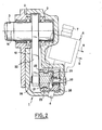
- the distributor 6 is mounted on one of the faces of the housing 1 so that its longitudinal axis makes an acute angle with the general plane of movement of the swing arm 22 (as can be seen in Figure 2 ), the end of the input member 4 of the transmission swiveling in a bearing 25 formed in the housing 1.
- the toothed sector 23 is in the form of a conical toothed sector formed on the face of the curved bar 21 directed on the side of the distributor 6, the curved bar 21 being connected, by its opposite face, to the swing arm 22.
- the inner end of the curved bar 21 is hingedly connected to the outer end of the swing arm 22 by an axis element 26 received in a ' bore 27 of the curved bar 21.
- the curved bar 21 is guided, in its circular movement, by a curved guide 28 extending in the chamber 10 of the housing 1 and mounted on the side wall of the latter, the guide 28 comprising projecting projections 29 received in corresponding grooves of the curved bar 21.
- the guide 28 is mounted in an adjustable manner on the wall of the housing 1 by means of spring bolts 29, the springs 30 extending between an internal head of each bolt 29 and a shoulder 31 of the guide 28.
- the outer end 12 of the tube 13 is advantageously fixed to the arm 11 by a plug 31 into which the pipe 9 from the distributor 6 opens, the other pipe of the distributor 6 opening into the chamber 10 of the housing 1.
- the latter selectively sends pressurized fluid from a pressure source via one or other of the pipes 8 or 9 to the either of the chambers of the hydraulic motor formed by the piston 19 in the cylinder 13, namely on the side of the piston 19 directed towards the plug 31 or in the chamber 10 formed by the housing 1.
- FIG. 5 and 6 differs essentially from the embodiment described above in that the curved cylinder in which the piston 19 moves is formed by an extension 113 of the housing 1.
- the inner wall 114 of the cylinder 113 separating the latter of the internal chamber 10 of the housing 1 at the same time forms the bearing 25 for the input member 4 of the multiplying transmission, that is to say the rotating member output of the hydraulic distributor 6, similar to the previous but received, this time, in a bore 110 formed in a cylindrical portion 111 of the housing 1, the axis of the distributor 6 passing through the axis of rotation 14 of the output member 5 of the transmission.
- the curved bar 121 forming the piston rod 19 and provided with the toothed sector 23 cooperating advantageously with the pinion 24 of the input member 4 of the transmission, is formed in one piece with the pivoting arm 122 itself secured to the shaft - outlet 3 of the mechanism which revolves in the housing 1 by means of bearings 102.
- the guiding in its curvilinear movement of the curved bar 121 is performed locally, at the level of the engagement zone between the toothed sector 23 and the pinion 24, by a guide 123 mounted on the wall of the housing and comprising an arcuate groove 130 opening in the direction of the pinion 24 and receiving a projection 129 formed on the face of the curved bar 122 opposite the toothed sector 23.
- the cylinder chamber 113 opposite the internal chamber 10 is closed by a plug 31 to which the working fluid distribution pipe 9 of the distributor is connected.
- the other working fluid distribution pipe 8 supplying the internal chamber 10 of the housing 1, formed directly in the latter.
- the axis of the distributor 6, and therefore of the input member 4 of the transmission is parallel to the general plane of movement of the oscillating arm 122, the drive pinion 24 being conical.
Abstract
Description
La présente invention concerne les mécanismes d'actionnement à assistance par fluide, typiquement pour mécanismes de servo-direction de véhicules automobiles, du type comprenant un organe de sortie destiné à être relié à un système mené à actionner et un organe d'entrée destiné à être relié à un système de commande d'actionnement par l'intermédiaire d'un accouplement à course morte et d'un distributeur à fluide utilisant cette course morte pour alimenter sélectivement les chambres de travail d'un moteur à fluide à double effet réalisant ladite assistance.The present invention relates to fluid assisted actuation mechanisms, typically for power steering mechanisms of motor vehicles, of the type comprising an output member intended to be connected to a driven system to be actuated and an input member intended to be connected to an actuation control system via a dead stroke coupling and a fluid distributor using this dead stroke to selectively supply the working chambers of a double-acting fluid motor performing said assistance.
Des agencements connus de ce type de mécanisme d'actionnement mettent en oeuvre un groupe fonctionnel comprenant:un boîtier de direction, le mécanisme d'actionnement à transmission multiplicatrice, et le distributeur hydraulique commandant le fonctionnement du mécanisme d'actionnement. Un exemple typique de ce type d'agencement est décrit par exemple dans le brevet US 2 410 049 ou dans le brevet français 2 364 802 au nom de la demanderesse et comporte, dans un boîtier de servo-direction, un organe d'entrée de transmission formant vis coopérant, par l'intermédiaire de chemins de roulements à billes, avec mécanisme de sortie réalisé sous la forme d'un écrou coaxial à la vis et au distributeur, l'écrou, à dépla-et cement linéaire, formant le piston du moteur d'assistance, comportant des dents de crémaillère engrenant avec un organe de sortie de transmission sous la forme d'un secteur denté solidaire de l'arbre de sortie du mécanisme.Known arrangements of this type of actuation mechanism implement a functional group comprising: a steering box, the actuation mechanism with multiplying transmission, and the hydraulic distributor controlling the operation of the actuation mechanism. A typical example of this type of arrangement is described for example in US Patent 2,410,049 or in French Patent 2,364,802 in the name of the Applicant and comprises, in a power steering box, an input member of transmission forming cooperating screw, by means of ball bearing raceways, with outlet mechanism produced in the form of a nut coaxial with the screw and the distributor, the nut, with linear displacement and cement, forming the piston of the assistance motor, comprising rack teeth meshing with a transmission output member in the form of a toothed sector integral with the output shaft of the mechanism.
Dans ces techniques connues, il se pose des problèmes d'adaptation in situ du groupe fonctionnel, tant pour des raisons d'encombrement que pour ce qui est des dispositions respectives de l'organe d'entrée et de l'organe de sortie.In these known techniques, there are problems of in situ adaptation of the functional group, both for reasons of space and in terms of the respective arrangements of the input member and the output member.
La présente invention a précisément pour objet de proposer un mécanisme d'actionnement à assistance par fluide du type défini ci-dessus, d'encombrement réduit, mettant en oeuvre un nombre également réduit d'éléments, avec une inertie mécanique opérationnelle minima, et offrant une grande versatilité vis-à-vis des dispositions respectives des organes d'entrée et de sortie du mécanisme.The object of the present invention is precisely to propose a fluid-assisted actuation mechanism of the type defined above, of reduced bulk, employing also a reduced number of elements, with minimal operational mechanical inertia, and offering great versatility with respect to the respective arrangements of the input and output members of the mechanism.
Pour ce faire, selon une caractéristique de l'invention, l'organe de sortie coopère avec l'organe d'entrée de façon à être mû dans son ensemble par ce dernier en rotation autour d'un axe, le moteur à fluide comprenant un cylindre en forme de secteur toroîdal coaxial audit axe et dans lequel se déplace à coulissement étanche un piston couplé à l'organe de sortie.To do this, according to a characteristic of the invention, the outlet member cooperates with the inlet member so as to be moved as a whole by the latter in rotation about an axis, the fluid motor comprising a cylinder in the shape of a toroidal sector coaxial with said axis and in which moves in sealed sliding a piston coupled to the output member.
Selon une autre caractéristique de l'invention, l'organe de sortie coopère directement en engrènement avec l'organe d'entrée, l'organe de sortie comportant typiquement un secteur denté coaxial audit axe et coopérant en engrènement avec un pignon de l'organe d'entrée.According to another characteristic of the invention, the outlet member cooperates directly in engagement with the inlet member, the outlet member typically comprising a toothed sector coaxial with said axis and cooperating in engagement with a pinion of the member entry.
Selon une caractéristique plus particulière de l'invention, l'organe de sortie forme tige courbe pour le piston du moteur.According to a more particular characteristic of the invention, the output member forms a curved rod for the piston of the engine.
Selon une autre caractéristique de l'invention, le cylindre de moteur fait partie d'un boîtier étanche renfermant la transmission et formant au moins une des chambres de travail du moteur.According to another characteristic of the invention, the engine cylinder is part of a sealed housing enclosing the transmission and forming at least one of the engine working chambers.
Avec un tel agencement, l'organe de sortie de la transmission est mû par l'organe d'entrée dans un mouvement de rotation autour d'un axe coïncidant typiquement avec l'arbre de. sortie du mécanisme d'actionnement, tandis que l'organe de sortie de la transmission joue simultanément le rôle de la tige de piston qui se déplace également suivant un trajet courbe coaxial audit axe, dans un agencement général compact et à faibles pertes mécaniques. De plus, l'engrènement entre le pignon de l'organe d'entrée et le secteur denté de l'organe de sortie peut s'effectuer de diverses manières, par exemple à angle droit, parallèlement ou avec un angle aigu dans un mode d'engrènement à secteur denté et pignon cônique.With such an arrangement, the output member of the transmission is moved by the input member in a rotational movement around an axis typically coinciding with the shaft. output of the actuating mechanism, while the output member of the transmission simultaneously plays the role of the piston rod which also moves along a curved path coaxial with said axis, in a generally compact arrangement and with low mechanical losses. In addition, the meshing between the pinion of the input member and the toothed sector of the output member can be carried out in various ways, for example at right angles, parallel or with an acute angle in a mode d '' toothed sector and bevel gear.
D'autres caractéristiques et avantages de la présente invention ressortiront de la description suivante de modes de réalisation, donnés à titre illustratif mais nullement limitatif, faite en relation avec les dessins annexés, sur lesquels :
- - la figure 1 est une vue en coupe transversale d'un premier mode de réalisation du mécanisme d'actionnement selon l'invention ;
- - la figure 2 est une vue schématique, partiellement en coupe, suivant la ligne II-II de la figure 1 ;
- - la figure 3 est une vue en coupe partielle suivant la ligne courbe III-III de la figure 1 ;
- - la figure 4 est une coupe transversale du cylindre d'assistance suivant la ligne IV-IV de la figure 1 ;
- - la figure 5 est une vue analogue à la figure 1 d'un autre mode de réalisation de l'invention ; et
- - la figure 6 est une vue en coupe suivant la ligne VI-VI de la figure 5.
- - Figure 1 is a cross-sectional view of a first embodiment of the actuation mechanism according to the invention;
- - Figure 2 is a schematic view, partially in section, along the line II-II of Figure 1;
- - Figure 3 is a partial sectional view along the curved line III-III of Figure 1;
- - Figure 4 is a cross section of the assistance cylinder along the line IV-IV of Figure 1;
- - Figure 5 is a view similar to Figure 1 of another embodiment of the invention; and
- - Figure 6 is a sectional view along line VI-VI of Figure 5.
Dans la description qui va suivre et sur les dessins, les éléments identiques ou analogues portent les mêmes chiffres de référence, éventuellement affectés d'un digit des centaines supplémentaire pour le second mode de réalisation.In the following description and in the drawings, the elements identical or analogous bear the same reference numbers, possibly assigned an additional hundreds digit for the second embodiment.
Dans le mode de réalisation des figures 1 à 4, le mécanisme comprend essentiellement un boîtier creux en forme de secteur 1, dans lequel tourillone au moyen de roulements 2 un arbre de sortie 3 destiné typiquement à être couplé à un mécanisme de direction des roues d'un véhicule automobile, une transmission multiplicatrice d'effort comprenant un organe d'entrée 4 et un organe de sortie 5, et un distributeur à fluide 6 interposé entre l'organe d'entrée de transmission 4 et un organe de commande 7 du mécanisme, relié typiquement à un volant de direction, par l'intermédiaire d'un accouplement à course morte pour fournir sélectivement dans des conduites de sortie 8 et 9 un fluide sous pression acheminé vers les chambres de travail respectives d'un moteur à fluide d'assistance.In the embodiment of Figures 1 to 4, the mechanism essentially comprises a hollow sector-
De façon générale, le distributeur 6 est un distributeur hydraulique connu en soi, du type coaxial à rotor tubulaire et douille ou du type à rotor en étoile, assurant lui-même la liaison mécanique à course morte entre l'organe de commande d'entrée 7 et l'organe d'entrée 4 de la transmission qui constitue en fait l'organe de sortie du distributeur'6.In general, the
Comme on le voit bien sur la figure 1, le boîtier plat en forme de secteur 1 définit une chambre interne en forme de secteur 10 à laquelle est reliée la canalisation de sortie de fluide de travail 8 du distributeur 6. Le boîtier 1 comporte en outre un bras radial 11 sur lequel est fixé hermétiquement une extrémité 12 d'un tube courbe 13 dont le centre de courbure est confondu avec l'axe 14 de l'arbre 3 et du secteur du boîtier. L'autre extrémité 15 du tube courbe est reçue en emmanchement étanche, au moyen de joints 16, dans une ouverture 17 formée dans la paroi adjacente 18 du boîtier 1. Dans le cylindre de vérin courbe constitué par le tube 13 se déplace à coulissement étanche un piston annulaire 19 fixé par une vis 20 à une barre courbe 21 ayant son centre de courbure confondu avec l'axe 14 et formant la tige du piston 19, Dans la position extreme représentée sur la figure 1, la barre courbe 21 s'étend tout au long du cylindre 13 pour se prolonger à l'intérieur de la chambre 10 du boîtier 1, l'extrémité intérieure de la barre 21 étant reliée à une extrémité d'un bras oscillant 22 rendu solidaire de l'arbre de sortie 3 et se débattant angulairement à l'intérieur de la chambre sectorielle 10 du boîtier 1.As can be clearly seen in FIG. 1, the flat sector-
Comme on le voit mieux sur les figures 2 à 4, la barre courbe 21, de section généralement trapézoïdale, présente sur une de ses faces un secteur denté 23 coopérant avec un pignon 24/sur l'organe d'entrée 4 de la transmission. Dans l'exemple représenté, le distributeur 6 est monté sur une des faces du boîtier 1 de façon à ce que son axe longitudinal fasse un angle aigu avec le plan général de débattement du bras oscillant 22 (comme on le voit bien sur la Figure 2), l'extrémité de l'organe d'entrée 4 de la transmission tourillonnant dans un palier
25 formé dans le boîtier 1. Dans ce cas, le secteur denté 23 se présente sous la forme d'un secteur denté cônique formé sur la face de la barre courbe 21 dirigés du côté du distributeur 6, la barre courbe 21 étant reliée, par sa face opposée, au bras oscillant 22. Dans le mode de réalisation représenté, l'extrémité intérieure de la barre courbe 21 est reliée de façon articulée à l'extrémité extérieure du bras oscillant 22 par un élément d'axe 26 reçu dans un'alésage 27 de la barre courbe 21.As best seen in Figures 2 to 4, the
25 formed in the
Comme on le voit bien sur les figures 2 et 3, la barre courbe 21 est guidée, dans son déplacement cireulaire, par un guide courbe 28 s'étendant dans la chambre 10 du boîtier 1 et monté sur la paroi latérale de ce dernier, le guide 28 comportant des saillies en vis à-vis 29 reçues dans des gorges correspondantes de la barre courbe 21. De préférence, pour permettre un réglage de l'engrènement entre le secteur denté 23 de la barre courbe 21 et le pignon 24 de l'organe d'entrée 4, le guide 28 est monté de façon réglable sur la paroi du boîtier 1 au moyen de boulons à ressort 29, les ressorts 30 s'étendant entre une tête interne de chaque boulon 29 et un épaulement 31 du guide 28.As can be seen in FIGS. 2 and 3, the
L'extrémité extérieure 12 du tube 13 est fixée avantageusement sur le bras 11 par un bouchon 31 dans lequel débouche la canalisation 9 provenant du distributeur 6, l'autre conduite du distributeur 6 débouchant dans la chambre 10 du boîtier 1. De cette façon, en fonction de la rotation de l'organe de commande d'entrée 7 du distributeur 6, ce dernier envoie sélectivement du fluide sous pression en provenance d'une source de pression par l'une ou l'autre des canalisations 8 ou 9 vers l'une ou l'autre des chambres du moteur hydraulique formées par le piston 19 dans le cylindre 13, à savoir du côté du piston 19 dirigé vers le bouchon 31 ou dans la chambre 10 formée par le boîtier 1. En fonction de la différence de pression ainsi créée de part et d'autre du piston19, celui-ci se déplace dans un trajet courbe le long du cylindre 13, déplaçant avec lui ladite tige courbe 21 et faisant osciller le bras 22 autour de l'axe 14,assistant ainsi la transmission mécanique entre l'organe d'entrée 4 et l'organe de sortie 5 qui regroupe, en l'occurrence, la barre courbe dentée 21, le bras oscillant 22 et l'arbre de sortie 3.The
Le mode de réalisation des Figures 5 et 6 se distingue essentiellement du mode de réalisation précédemment décrit en ce sens que le cylindre courbe dans lequel se déplace le piston 19 est formé par une extension 113 du boîtier 1. La paroi intérieure 114 du cylindre 113 séparant ce dernier de la chambre interne 10 du boîtier 1 forme en même temps le palier 25 pour l'organe d'entrée 4 de la transmission multiplicatrice, c'est-à-dire l'organe tournant de sortie du distributeur hydraulique 6,analogue au précédent mais reçu, cette fois, dans un alésage 110 formé dans une portion cylindrique 111 du boîtier 1,l'àxe du distributeur 6 passant par l'axe de rotation 14 de l'organe de sortie 5 de la transmission. Dans ce mode de réalisation,la barre courbe 121,formant la tige du piston 19 et pourvue du secteur denté 23 coopérant avec avantageusement le pignon 24 de l'organe d'entrée 4 de la transmission,est formée d'une seule pièce avec le bras pivotant 122 lui-même solidarisé à l'arbre - de sortie 3 du mécanisme qui tourillone dans le boîtier 1 au moyen de coussinets 102. De ce fait, le guidage dans son déplacement curviligne de la barre courbe 121 est effectué localement, au niveau de la zone d'engrènement entre le secteur denté 23 et le pignon 24, par un guide 123 monté sur la paroi du boîtier et comprenant une gorge arquée 130 ouvrant dans la direction du pignon 24 et recevant une saillie 129 formée sur la facé de la barre courbe 122 opposée au secteur denté 23. Comme précédemment, la chambre du cylindre 113 opposée à la chambre interne 10 est fermée par un bouchon 31 auquel se raccorde la canalisation de distribution de fluide de travail 9 du distributeur. Sur la Figure 5, on remarquera, dans ce mode de réalisation,l'autre canalisation de distribution de fluide de travail 8,alimentant la chambre interne 10 du boîtier 1, formée directement dans ce dernier. Dans l'exemple représenté, l'axe du distributeur 6, et donc de l'organe d'entrée 4 de la transmission, est parallèle au plan général de débattement du bras oscillant 122, le pignon d'attaque 24 étant cônique.The embodiment of Figures 5 and 6 differs essentially from the embodiment described above in that the curved cylinder in which the
Quoique la présente invention ait été décrite en relation avec des modes de réalisation particuliers, elle ne s'en trouve pas limitée mais est au contraire susceptible de modifications et de variantes qui apparaîtront à l'homme de l'art.Although the present invention has been described in relation to particular embodiments, it is not limited thereto but is on the contrary subject to modifications and variants which will appear to those skilled in the art.
Claims (10)
Applications Claiming Priority (2)
| Application Number | Priority Date | Filing Date | Title |
|---|---|---|---|
| ES506439A ES8302220A1 (en) | 1981-09-23 | 1981-09-23 | Actuating mechanism with fluid assistance, particularly for a servo steering system. |
| ES506439 | 1981-09-23 |
Publications (2)
| Publication Number | Publication Date |
|---|---|
| EP0075511A2 true EP0075511A2 (en) | 1983-03-30 |
| EP0075511A3 EP0075511A3 (en) | 1984-04-11 |
Family
ID=8483114
Family Applications (1)
| Application Number | Title | Priority Date | Filing Date |
|---|---|---|---|
| EP82401666A Withdrawn EP0075511A3 (en) | 1981-09-23 | 1982-09-14 | Actuating mechanism with fluid assistance, particularly for a servo steering system |
Country Status (3)
| Country | Link |
|---|---|
| EP (1) | EP0075511A3 (en) |
| JP (1) | JPS58106206A (en) |
| ES (1) | ES8302220A1 (en) |
Cited By (3)
| Publication number | Priority date | Publication date | Assignee | Title |
|---|---|---|---|---|
| WO2007003000A1 (en) * | 2005-06-30 | 2007-01-11 | James Antony Kells | Toroidal ram actuator |
| WO2014184051A1 (en) * | 2013-05-16 | 2014-11-20 | Zf Lenksysteme Gmbh | Steering gearing having hydraulic assistance by means of a vane |
| WO2014187664A1 (en) * | 2013-05-22 | 2014-11-27 | Zf Lenksysteme Gmbh | Steering gearing having hydraulic assistance by means of a rotary piston |
Citations (4)
| Publication number | Priority date | Publication date | Assignee | Title |
|---|---|---|---|---|
| US2362930A (en) * | 1943-09-15 | 1944-11-14 | Mack Mfg Corp | Power assisted steering gear |
| DE2001721A1 (en) * | 1970-01-15 | 1971-07-22 | Adwest Eng Ltd | Steering device for motor vehicles |
| GB2056387A (en) * | 1979-08-01 | 1981-03-18 | Zahnradfabrik Friedrichshafen | Hydraulically assisted rack and pinion steering |
| EP0038493A2 (en) * | 1980-04-17 | 1981-10-28 | Trw Inc. | Power steering apparatus |
-
1981
- 1981-09-23 ES ES506439A patent/ES8302220A1/en not_active Expired
-
1982
- 1982-09-14 EP EP82401666A patent/EP0075511A3/en not_active Withdrawn
- 1982-09-22 JP JP57164186A patent/JPS58106206A/en active Pending
Patent Citations (4)
| Publication number | Priority date | Publication date | Assignee | Title |
|---|---|---|---|---|
| US2362930A (en) * | 1943-09-15 | 1944-11-14 | Mack Mfg Corp | Power assisted steering gear |
| DE2001721A1 (en) * | 1970-01-15 | 1971-07-22 | Adwest Eng Ltd | Steering device for motor vehicles |
| GB2056387A (en) * | 1979-08-01 | 1981-03-18 | Zahnradfabrik Friedrichshafen | Hydraulically assisted rack and pinion steering |
| EP0038493A2 (en) * | 1980-04-17 | 1981-10-28 | Trw Inc. | Power steering apparatus |
Cited By (4)
| Publication number | Priority date | Publication date | Assignee | Title |
|---|---|---|---|---|
| WO2007003000A1 (en) * | 2005-06-30 | 2007-01-11 | James Antony Kells | Toroidal ram actuator |
| US7895935B2 (en) | 2005-06-30 | 2011-03-01 | James Antony Kells | Toroidal ram actuator |
| WO2014184051A1 (en) * | 2013-05-16 | 2014-11-20 | Zf Lenksysteme Gmbh | Steering gearing having hydraulic assistance by means of a vane |
| WO2014187664A1 (en) * | 2013-05-22 | 2014-11-27 | Zf Lenksysteme Gmbh | Steering gearing having hydraulic assistance by means of a rotary piston |
Also Published As
| Publication number | Publication date |
|---|---|
| JPS58106206A (en) | 1983-06-24 |
| EP0075511A3 (en) | 1984-04-11 |
| ES506439A0 (en) | 1983-01-01 |
| ES8302220A1 (en) | 1983-03-01 |
Similar Documents
| Publication | Publication Date | Title |
|---|---|---|
| CA2610056C (en) | Turboprop engine equipped with an adjustable blade direction assembly | |
| EP0072311B1 (en) | Hydraulic distributor for a servomotor with return towards rest position | |
| EP0066507B1 (en) | Rotative hydraulic distributor for a hydraulic actuating system | |
| EP0075511A2 (en) | Actuating mechanism with fluid assistance, particularly for a servo steering system | |
| EP1538067B1 (en) | Vehicle axle and actuator for said axle | |
| FR2474427A1 (en) | STEERING DEVICE OF RACK AND PINION TYPE FOR VEHICLES, COMPRISING MEANS FOR EXHAUSTING THE AIR AND BUBBLES CONTAINED IN THE ENGINE CYLINDER | |
| EP0112249B1 (en) | Power steering for motor vehicles | |
| EP0136234A2 (en) | Rack-and-pinion servosteering device | |
| FR2641214A1 (en) | DEVICE FOR BENDING THIN METAL PIPING | |
| FR2814297A1 (en) | ELECTRICALLY POWERED ACTUATOR, PARTICULARLY FOR CONTROLLING A BICYCLE COMPONENT | |
| EP0130912B1 (en) | Swash plate mechanism, especially for the drive of a pump | |
| EP0075519B1 (en) | Actuating mechanism with fluid assistance, particularly for the servo steering system of an automotive vehicle | |
| FR2715415A1 (en) | Drive mounted on a removal device for moving sections of bridge. | |
| WO1995023293A1 (en) | Direct drive valve | |
| FR2653062A1 (en) | DEVICE FOR THE ELASTIC DEFORMATION OF A PRINTING PLATE FIXED ON A PLATE HOLDER CYLINDER. | |
| FR2633863A1 (en) | Handling robot with circular horizontal movement | |
| EP0007861B1 (en) | Adjusting device for a rear-view mirror, particularly for a vehicle | |
| FR2503274A1 (en) | Spray pump for agricultural substances - has remote control of stroke length through double eccentric on drive crank | |
| EP0021950B1 (en) | Power steering for automotive vehicle | |
| FR2654186A1 (en) | ORIENTABLE BEAM LIGHTHOUSE. | |
| EP0254645A1 (en) | Servosteering device for automotive vehicles, of the type comprising a servosteering valve | |
| EP0331854B1 (en) | Fluid actuator for driving a rotary shaft | |
| FR2783451A1 (en) | ROBOT FOR HANDLING AN OBJECT | |
| FR2721576A1 (en) | Rack-and-pinion steering assisted by a servomotor. | |
| FR2570130A1 (en) | RADIAL PISTON HYDRAULIC MACHINE |
Legal Events
| Date | Code | Title | Description |
|---|---|---|---|
| PUAI | Public reference made under article 153(3) epc to a published international application that has entered the european phase |
Free format text: ORIGINAL CODE: 0009012 |
|
| 17P | Request for examination filed |
Effective date: 19820922 |
|
| AK | Designated contracting states |
Designated state(s): DE FR GB IT |
|
| PUAL | Search report despatched |
Free format text: ORIGINAL CODE: 0009013 |
|
| AK | Designated contracting states |
Designated state(s): DE FR GB IT |
|
| STAA | Information on the status of an ep patent application or granted ep patent |
Free format text: STATUS: THE APPLICATION HAS BEEN WITHDRAWN |
|
| 18W | Application withdrawn |
Withdrawal date: 19840507 |
|
| RIN1 | Information on inventor provided before grant (corrected) |
Inventor name: BACARDIT, JUAN SIMON |