EP1921285B1 - Motorcycle exhaust system and motorcycle provided with exhaust system - Google Patents
Motorcycle exhaust system and motorcycle provided with exhaust system Download PDFInfo
- Publication number
- EP1921285B1 EP1921285B1 EP07254171A EP07254171A EP1921285B1 EP 1921285 B1 EP1921285 B1 EP 1921285B1 EP 07254171 A EP07254171 A EP 07254171A EP 07254171 A EP07254171 A EP 07254171A EP 1921285 B1 EP1921285 B1 EP 1921285B1
- Authority
- EP
- European Patent Office
- Prior art keywords
- exhaust
- pipe
- casing
- tail
- cap
- Prior art date
- Legal status (The legal status is an assumption and is not a legal conclusion. Google has not performed a legal analysis and makes no representation as to the accuracy of the status listed.)
- Not-in-force
Links
Images


Classifications
-
- F—MECHANICAL ENGINEERING; LIGHTING; HEATING; WEAPONS; BLASTING
- F01—MACHINES OR ENGINES IN GENERAL; ENGINE PLANTS IN GENERAL; STEAM ENGINES
- F01N—GAS-FLOW SILENCERS OR EXHAUST APPARATUS FOR MACHINES OR ENGINES IN GENERAL; GAS-FLOW SILENCERS OR EXHAUST APPARATUS FOR INTERNAL COMBUSTION ENGINES
- F01N1/00—Silencing apparatus characterised by method of silencing
- F01N1/08—Silencing apparatus characterised by method of silencing by reducing exhaust energy by throttling or whirling
-
- F—MECHANICAL ENGINEERING; LIGHTING; HEATING; WEAPONS; BLASTING
- F01—MACHINES OR ENGINES IN GENERAL; ENGINE PLANTS IN GENERAL; STEAM ENGINES
- F01N—GAS-FLOW SILENCERS OR EXHAUST APPARATUS FOR MACHINES OR ENGINES IN GENERAL; GAS-FLOW SILENCERS OR EXHAUST APPARATUS FOR INTERNAL COMBUSTION ENGINES
- F01N1/00—Silencing apparatus characterised by method of silencing
- F01N1/003—Silencing apparatus characterised by method of silencing by using dead chambers communicating with gas flow passages
-
- F—MECHANICAL ENGINEERING; LIGHTING; HEATING; WEAPONS; BLASTING
- F01—MACHINES OR ENGINES IN GENERAL; ENGINE PLANTS IN GENERAL; STEAM ENGINES
- F01N—GAS-FLOW SILENCERS OR EXHAUST APPARATUS FOR MACHINES OR ENGINES IN GENERAL; GAS-FLOW SILENCERS OR EXHAUST APPARATUS FOR INTERNAL COMBUSTION ENGINES
- F01N1/00—Silencing apparatus characterised by method of silencing
- F01N1/08—Silencing apparatus characterised by method of silencing by reducing exhaust energy by throttling or whirling
- F01N1/10—Silencing apparatus characterised by method of silencing by reducing exhaust energy by throttling or whirling in combination with sound-absorbing materials
-
- F—MECHANICAL ENGINEERING; LIGHTING; HEATING; WEAPONS; BLASTING
- F01—MACHINES OR ENGINES IN GENERAL; ENGINE PLANTS IN GENERAL; STEAM ENGINES
- F01N—GAS-FLOW SILENCERS OR EXHAUST APPARATUS FOR MACHINES OR ENGINES IN GENERAL; GAS-FLOW SILENCERS OR EXHAUST APPARATUS FOR INTERNAL COMBUSTION ENGINES
- F01N13/00—Exhaust or silencing apparatus characterised by constructional features ; Exhaust or silencing apparatus, or parts thereof, having pertinent characteristics not provided for in, or of interest apart from, groups F01N1/00 - F01N5/00, F01N9/00, F01N11/00
- F01N13/04—Exhaust or silencing apparatus characterised by constructional features ; Exhaust or silencing apparatus, or parts thereof, having pertinent characteristics not provided for in, or of interest apart from, groups F01N1/00 - F01N5/00, F01N9/00, F01N11/00 having two or more silencers in parallel, e.g. having interconnections for multi-cylinder engines
-
- F—MECHANICAL ENGINEERING; LIGHTING; HEATING; WEAPONS; BLASTING
- F01—MACHINES OR ENGINES IN GENERAL; ENGINE PLANTS IN GENERAL; STEAM ENGINES
- F01N—GAS-FLOW SILENCERS OR EXHAUST APPARATUS FOR MACHINES OR ENGINES IN GENERAL; GAS-FLOW SILENCERS OR EXHAUST APPARATUS FOR INTERNAL COMBUSTION ENGINES
- F01N13/00—Exhaust or silencing apparatus characterised by constructional features ; Exhaust or silencing apparatus, or parts thereof, having pertinent characteristics not provided for in, or of interest apart from, groups F01N1/00 - F01N5/00, F01N9/00, F01N11/00
- F01N13/18—Construction facilitating manufacture, assembly, or disassembly
- F01N13/1805—Fixing exhaust manifolds, exhaust pipes or pipe sections to each other, to engine or to vehicle body
-
- F—MECHANICAL ENGINEERING; LIGHTING; HEATING; WEAPONS; BLASTING
- F01—MACHINES OR ENGINES IN GENERAL; ENGINE PLANTS IN GENERAL; STEAM ENGINES
- F01N—GAS-FLOW SILENCERS OR EXHAUST APPARATUS FOR MACHINES OR ENGINES IN GENERAL; GAS-FLOW SILENCERS OR EXHAUST APPARATUS FOR INTERNAL COMBUSTION ENGINES
- F01N2230/00—Combination of silencers and other devices
- F01N2230/04—Catalytic converters
-
- F—MECHANICAL ENGINEERING; LIGHTING; HEATING; WEAPONS; BLASTING
- F01—MACHINES OR ENGINES IN GENERAL; ENGINE PLANTS IN GENERAL; STEAM ENGINES
- F01N—GAS-FLOW SILENCERS OR EXHAUST APPARATUS FOR MACHINES OR ENGINES IN GENERAL; GAS-FLOW SILENCERS OR EXHAUST APPARATUS FOR INTERNAL COMBUSTION ENGINES
- F01N2240/00—Combination or association of two or more different exhaust treating devices, or of at least one such device with an auxiliary device, not covered by indexing codes F01N2230/00 or F01N2250/00, one of the devices being
- F01N2240/36—Combination or association of two or more different exhaust treating devices, or of at least one such device with an auxiliary device, not covered by indexing codes F01N2230/00 or F01N2250/00, one of the devices being an exhaust flap
-
- F—MECHANICAL ENGINEERING; LIGHTING; HEATING; WEAPONS; BLASTING
- F01—MACHINES OR ENGINES IN GENERAL; ENGINE PLANTS IN GENERAL; STEAM ENGINES
- F01N—GAS-FLOW SILENCERS OR EXHAUST APPARATUS FOR MACHINES OR ENGINES IN GENERAL; GAS-FLOW SILENCERS OR EXHAUST APPARATUS FOR INTERNAL COMBUSTION ENGINES
- F01N2490/00—Structure, disposition or shape of gas-chambers
- F01N2490/02—Two or more expansion chambers in series connected by means of tubes
- F01N2490/04—Two or more expansion chambers in series connected by means of tubes the gases flowing longitudinally from inlet to outlet only in one direction
-
- F—MECHANICAL ENGINEERING; LIGHTING; HEATING; WEAPONS; BLASTING
- F01—MACHINES OR ENGINES IN GENERAL; ENGINE PLANTS IN GENERAL; STEAM ENGINES
- F01N—GAS-FLOW SILENCERS OR EXHAUST APPARATUS FOR MACHINES OR ENGINES IN GENERAL; GAS-FLOW SILENCERS OR EXHAUST APPARATUS FOR INTERNAL COMBUSTION ENGINES
- F01N2490/00—Structure, disposition or shape of gas-chambers
- F01N2490/08—Two or more expansion chambers in series separated by apertured walls only
-
- F—MECHANICAL ENGINEERING; LIGHTING; HEATING; WEAPONS; BLASTING
- F01—MACHINES OR ENGINES IN GENERAL; ENGINE PLANTS IN GENERAL; STEAM ENGINES
- F01N—GAS-FLOW SILENCERS OR EXHAUST APPARATUS FOR MACHINES OR ENGINES IN GENERAL; GAS-FLOW SILENCERS OR EXHAUST APPARATUS FOR INTERNAL COMBUSTION ENGINES
- F01N2490/00—Structure, disposition or shape of gas-chambers
- F01N2490/12—Chambers having variable volumes
-
- F—MECHANICAL ENGINEERING; LIGHTING; HEATING; WEAPONS; BLASTING
- F01—MACHINES OR ENGINES IN GENERAL; ENGINE PLANTS IN GENERAL; STEAM ENGINES
- F01N—GAS-FLOW SILENCERS OR EXHAUST APPARATUS FOR MACHINES OR ENGINES IN GENERAL; GAS-FLOW SILENCERS OR EXHAUST APPARATUS FOR INTERNAL COMBUSTION ENGINES
- F01N2560/00—Exhaust systems with means for detecting or measuring exhaust gas components or characteristics
- F01N2560/02—Exhaust systems with means for detecting or measuring exhaust gas components or characteristics the means being an exhaust gas sensor
- F01N2560/025—Exhaust systems with means for detecting or measuring exhaust gas components or characteristics the means being an exhaust gas sensor for measuring or detecting O2, e.g. lambda sensors
-
- F—MECHANICAL ENGINEERING; LIGHTING; HEATING; WEAPONS; BLASTING
- F01—MACHINES OR ENGINES IN GENERAL; ENGINE PLANTS IN GENERAL; STEAM ENGINES
- F01N—GAS-FLOW SILENCERS OR EXHAUST APPARATUS FOR MACHINES OR ENGINES IN GENERAL; GAS-FLOW SILENCERS OR EXHAUST APPARATUS FOR INTERNAL COMBUSTION ENGINES
- F01N9/00—Electrical control of exhaust gas treating apparatus
Definitions
- the present invention relates to an exhaust system for a motorcycle that is provided with an exhaust pipe that is connected to an exhaust port of an engine, and a muffler (or silencer) that is connected to the exhaust pipe, and a motorcycle that is provided with the exhaust system.
- motorcycle exhaust systems It is normal for motorcycle exhaust systems to be provided with an exhaust pipe connected to an engine and a muffler connected to the exhaust pipe.
- Some types of the above-described muffler are provided with a casing that is formed to surround a tail pipe that is connected to the exhaust pipe, and a tail cap that acts as an exterior part that is fitted to a rear end wall of the casing.
- This type of tail cap is sometimes formed from an integrated bottom section, annular section, and expanding section.
- the bottom section covers the rear end wall of the casing
- the annular section covers a rear periphery edge portion of the casing
- the expanding section expands to the rear so as to connect the annular section and the bottom section.
- the bottom section, the annular section and the expanding section form a generally recess like shape when viewed in a cross section.
- This type of muffler sometimes generates exhaust flow noise due to entry/exit of exhaust gas from the tail pipe caused by exhaust pulsation.
- a structure is sometimes adopted in which the tail pipe passes through a tail hole that is formed in the bottom section of the tail cap, and extends to the rear (see , for example, JP-A-2001-303925 ).
- the applicant of the present patent application has investigated a structure in which the tail pipe is positioned such that a rear end surface thereof is generally flush with an opening edge of the tail hole of the tail cap.
- An aim of the invention is to provide an exhaust system for a motorcycle and a motorcycle provided with the exhaust system that can improve saleability from an external appearance perspective by inhibiting generation of flow noise without worsening external appearance.
- An aspect of the invention is an exhaust system for a motorcycle including an exhaust pipe connected to an engine and a muffler (or silencer) connected to the exhaust pipe.
- the muffler includes a casing, in a rear end section of the muffler, that has a rear end wall and that is formed to surround a rear section of the exhaust pipe, and a tail cap that is disposed to surround an outer side of the rear end wall of the casing.
- a tail hole is formed in the rear end wall such that a gap is left with respect to an outer diameter of an end portionof the rear section of the exhaust pipe.
- the gap between the tail hole and the end portion of the rear section of the exhaust pipe is in communication with a space formed between the rear end wall and the tail cap, and a passage is formed that communicates the space and an outside space.
- the tail hole is formed in the rear end wall of the casing such that the gap is left with respect to the rear end of the exhaust pipe, the gap is formed to be in communication with the space formed between the rear end wall and the tail cap, and the passage communicates the space and the outside space.
- a rear end surface of the exhaust pipe can be disposed to be generally flush with a tail hole of a tail cap, whereby it is possible to improve saleability from the perspective of the external appearance of the muffler.
- Fig. 1 to Fig. 12 are figures that illustrate an exhaust system for a motorcycle according to the embodiment of the invention.
- the terms front and rear, and left and right as used in this embodiment indicate the front and rear and the left and right when viewed from a rider seated on a seat.
- a motorcycle 1 includes a twin spar vehicle body frame 2, an engine 3 that is mounted on the vehicle body frame 2, and a front wheel 4, and a rear wheel 5 that are disposed at the front and rear of the vehicle body frame 2.
- the vehicle body frame 2 includes a head pipe 6 that is disposed at the front end of the vehicle body frame 2; left and right main frames 2a that extend diagonally downward toward the rear while expanding outwards to the left and right from the head pipe 6; left and right rear frames 2b that are contiguous with the main frames 2a and that extend and curve downwards; and left and right seat rails 2c that extend diagonally upward to the rear from the rear frames 2b.
- a front fork 7 is turnably supported by the head pipe 6 so as to be capable of being steered to the left and right.
- the front wheel 4 is rotatably supported by a lower end section of the front fork 7, and a steering handle 8 is fixed to an upper end section of the front fork 7.
- a front end section of a rear arm 9 is pivotably supported via a pivot shaft 10 at a lower end section of the left and right rear frames 2b such that the rear arm 9 is capable of swinging upward and downward.
- the rear wheel 5 is pivotably supported by a rear end section of the rear arm 9.
- a straddle type main seat 11, a straddle type tandem seat 12 that is positioned to the rear side of the main seat 11 are mounted on the left and right seat rails 2c.
- a tank cover 13, which is an exterior part, is disposed to the front side of the main seat 11.
- the engine 3 is a four stroke, four cylinder V-type engine that has left and right front side cylinders and left and right rear side cylinders that are disposed to form a V-shaped banks.
- An engine upper section is supported by and suspended from left and right suspension brackets 15, 15 that are fixed to the left and right main frames 2a, and an engine rear wall is supported in a suspended manner by a suspension bracket 15a fixed to the rear frames 2b etc.
- the engine 3 has a structure in which a crank case 20 that houses a crank shaft 19 is connected to lower mating surfaces of front and rear cylinder blocks 17, 18 that form the V shaped banks, upper mating surfaces of the front and rear cylinder blocks 17, 18 are connected to front and rear cylinder heads 21, 22, and front and rear head covers 23, 24 are attached to the front and rear cylinder heads 21, 22.
- a transmission case 20a that houses a change gear mechanism (not shown) is formed to be integrally connected with a rear side of the crank case 20.
- An upper wall and a lower wall of the transmission case 20a are fixed by tightened bolts to the rear frames 2b.
- 25 is an engine force output shaft.
- An intake system 29 of the engine 3 is provided with left and right front side and rear side intake pipes 26, 27, a throttle body (not shown), and a shared air cleaner (not shown).
- the left and right front side and rear side intake pipes 26, 27 are connected to a V shaped bank inside wall of the front and rear cylinder heads 21, 22 so as to communicate with left and right front and rear intake ports (not shown).
- the throttle body is connected to the left and right front side and rear side intake pipes 26, 27, and the shared air cleaner communicates with the throttle body.
- the air cleaner is disposed beneath the tank cover 13 between the left and right main frames 2a, and the left and right front side and rear side intake pipes 26, 27 are formed to extend generally perpendicularly upward from the V shape bank inside wall.
- left and right intake ducts 14, 14 that supply air to the engine 3 are disposed to the left and right sides of the tank cover 13. The left and right intake ducts 14 communicate with the air cleaner.
- An exhaust system 30 of the engine 3 includes four exhaust pipes 31 connected to the engine 3, a single exhaust gas chamber 32 connected to the exhaust pipe 31, and left and right mufflers 33, 33 connected to the exhaust gas chamber 32. More specifically, the exhaust system 30 has the following structure.
- the exhaust pipe 31 includes left and right lateral exhaust pipes (engine side exhaust pipes) 34, 34, left and right vertical exhaust pipes (engine side exhaust pipes) 35, 35, downstream side exhaust pipes 33a, 33a, and tail pipes 51, 51.
- the left and right lateral exhaust pipes 34, 34 are connected so as to communicate with left and right front exhaust ports that open in a V shaped bank outside wall (front side wall) of the front cylinder head 21.
- the left and right vertical exhaust pipes 35, 35 are connected so as to communicate with left and right rear exhaust ports that open in a V shaped outside wall (rear side wall) of the cylinder head 22.
- the downstream side exhaust pipes 33a, 33a are connected to the exhaust gas chamber 32, and the tail pipes 51, 51 are connected to the downstream side exhaust pipes 33a, 33a.
- the left and right lateral exhaust pipes 34 include a downward slanting section 34a, a horizontal section 34b, and a horizontal curved section 34c.
- the downward slanting section 34a protrudes outwards toward the vehicle width direction outer side from the cylinder head 21 while extending downwards.
- the horizontal section 34b extends generally linearly to the rear from a lower end of the slanting section 34a along a lower side of the crank case 20.
- the horizontal curved section 34c curves and extends in the vehicle width direction inner side from a rear end of the horizontal section 34b.
- the pair of left and right horizontal sections 34b are connected and communicate with each other via a communication pipe 36 that extends in the vehicle width direction.
- the left and right vertical exhaust pipes 35 include a vertical curved section 35a, and a perpendicular section 35b.
- the vertical curved section 35a curves and extends downwards to the rear side of the transmission case 20a from the cylinder head 22.
- the perpendicular section 35b is contiguous with the vertical curved section 35a and extends downwards in a generally linear manner.
- the exhaust gas chamber 32 is disposed between the transmission case 20a of the engine 3 and the rear wheel 5, and below the rear arm 9 including the pivot shaft 10.
- the exhaust gas chamber 32 has a front flange 32a that is formed to protrude outwards at a front end of the exhaust gas chamber 32, and left and right flanges 32b, 32b that are formed to protrude upwards at left and right side edge sections of an upper wall of the exhaust gas chamber 32.
- the front flange 32a is attached to the crank case 20, and the left and right flanges 32b, 32b are attached to the rear frame 2b via a bracket, not shown.
- the exhaust gas chamber 32 includes a chamber body 37, first, second and third expansion chambers a to c, a first communicating passage 39, and a second communicating passage 40.
- the chamber body 37 is a sealed box that is formed by joining respective outer periphery edge sections of an upper member 37a and a lower member 37b.
- the first, second and third expansion chambers a to c are defined by first and second partition walls 38a, 38b and extend in the front-rear direction inside of the chamber body 37.
- the first communication passage 39 communicates between the first expansion chamber a and the second expansion chamber b.
- the second communicating passage 40 communicates between the second expansion chamber b and the third expansion chamber c.
- the first to third expansion chambers a to c are arranged from the front side in the order of the first expansion chamber a, the third expansion chamber c, the second expansion chamber b.
- the second expansion chamber b is positioned between the first expansion chamber a to which the left and right lateral exhaust pipes 34 and the left and right vertical exhaust pipes 35 are connected, and the third expansion chamber c to which the left and right mufflers 33 are connected.
- the volume of the first expansion chamber a is set to be larger than the volume of the second and the third expansion chambers b, c, and the volume of the second expansion chamber b is set to be larger than the volume of the third expansion chamber c.
- the chamber body 37 when viewed from above, has a generally hexagonal shape, and includes a front end wall 37c; left and right front slanting walls 37d, 37d that extend diagonally rearwards while expanding to the outside from the front end wall 37c; left and right side walls 37e, 37e that extend to the rear from the left and right front slanting walls 37d; and a rear wall 37f that extends in the vehicle width direction to connect between respective rear ends of the left and right side walls 37e.
- the horizontal curved sections 34c, 34c of the left and right lateral exhaust pipes 34 are connected to the left and right front slanting walls 37d of the chamber body 37 so as to communicate with the first expansion chamber a.
- exhaust gas flowing through the left and right lateral exhaust pipes 34 flows in to the first expansion chamber a from the outside in the vehicle width direction toward the inside in the vehicle width direction.
- the right lateral exhaust pipe 34 includes an extending section 34d that is contiguous with the horizontal curved section 34c and extends towards a central portion within the first expansion chamber a.
- the extending section 34d is positioned so as to open in the first expansion chamber a to the rear side of the left and right vertical exhaust pipes 35.
- the opening of the extending section 34d is in a central portion in the vehicle width direction of both of the exhaust pipes 35.
- the perpendicular sections 35b, 35b of the left and right vertical exhaust pipes 35, 35 are disposed in a line in the vehicle width direction and are connected in the vicinity of the front end wall 37c of the chamber body 37 so as to communicate with the first expansion chamber a. Accordingly, exhaust gas flowing through the left and right vertical exhaust pipes 35 flows within the first expansion chamber a from the upper side in the upward-downward direction toward the downward side in the upward-downward direction.
- a boss 37h is formed in a vehicle width direction inside end portion of an upper wall 37g of the chamber body 37 so as to communicate with the first expansion chamber a.
- a detection member 42a of an oxygen concentration detection sensor 42 is inserted in the boss 37h so as to be positioned within the first expansion chamber a.
- the oxygen concentration detection sensor 42 is surrounded by the chamber body 37, the left and right rear frames 2b, the pivot shaft 10, and the rear arm 9, and is thereby inhibited from being damaged by external forces.
- the oxygen concentration detection sensor 42 is disposed at a position inside the first expansion chamber a that is away from a merging portion A of the left and right lateral exhaust pipes 34 and the left and right vertical exhaust pipes 35. More specifically, the extending section 34d is disposed such that exhaust gas is led away from the oxygen concentration detection sensor 42. In addition, the structure is configured such that exhaust gas from each exhaust pipe is mixed together, and the mixed gas is brought into contact with the detection member 42a of the oxygen concentration detection sensor 42.
- the first communicating passage 39 is disposed so as to pass through the first and second partition walls 38a, 38b that form the third expansion chamber c, and communicate with the first expansion chamber a and the second expansion chamber b.
- the first communicating passage 39 when viewed from above, is disposed at the opposite side of the chamber body 37 from the oxygen concentration detection sensor 42, and an exhaust gas inflow port 39a of the first communication passage 39 is disposed in the vicinity of the exhaust gas merging portion A of the first expansion chamber a.
- a catalyst 43 is disposed in the first communication passage 39.
- the catalyst 43 has a structure in which a honeycomb structure catalyst body 43b that purifies exhaust gas is disposed inside a metal tubular body 43a that forms the communicating passage 39.
- the catalyst 43 has an elliptical shape when viewed in a cross section, and is disposed such that the long axis of the elliptical shape extends in the vehicle width direction (refer to FIG. 7 ).
- the second communicating passage 40 is structured to pass through the second partition wall 38b and to connect the second expansion chamber b and the third expansion chamber c. Further, the second communicating passage 40 is disposed in the vicinity of the right side wall 37e of the chamber body 37. The second communicating passage 40 is disposed in alignment with the first communication passage 39 to the right side thereof, and the exhaust gas inflow port 40a of the second communicating passage 40 is disposed at a position that is offset in the vehicle width direction from an exhaust gas outflow port 39b of the first communication passage 39.
- Exhaust gas from each cylinder passes along the left and right lateral exhaust pipes 34 and the left and right vertical exhaust pipes 35, and flows in to the first expansion chamber a of the exhaust gas chamber 32.
- the exhaust gas which merges together in the first expansion chamber a, flows in to the second expansion chamber b via the catalyst 43 of the first communication passage 39.
- the exhaust gas then passes from the second expansion chamber b to the second communicating passage 40, and flows in to the third expansion chamber c. Then, the exhaust gas flows from the third expansion chamber c through the left and right mufflers 33 and is exhausted to the outside.
- a variable passage area valve 45 is disposed in the second communicating passage 40 and is structured so at to be capable of adjusting the passage area of the communicating passage 40.
- the variable passage area valve 45 includes a communicating pipe 45a, a valve shaft 45b, and a valve plate 45c.
- the communicating pipe 45a has a tubular shape and forms the second communicating passage 40.
- the valve shaft 45b is disposed to pass through the communicating pipe 45a in the vehicle width direction, and the valve plate 45c is fixed to the valve shaft 45b so as to be disposed within the communicating pipe 45a.
- the valve shaft 45b is disposed to extend in the vehicle width direction, and a right end section passes through the right side wall 37e of the chamber body 37 and protrudes in the outward direction.
- a driven pulley 46 is fitted to a protruding portion 45d of the valve shaft 45b.
- the driven pulley 46 is connected to a drive pulley 49 that is fitted to a rotating shaft of a drive motor 48 via a cable 47.
- the drive motor 48 is disposed inside a side cover 50 at the lower side of the seat rails 2c.
- the variable passage area valve 45 is controlled to open and close by a controller, not shown.
- the controller detects an engine operation state based on an engine speed, engine load and the like. When the engine operation state is in a low speed region, the controller controls the variable passage area valve 45 to close, and when the engine operation state is in a middle or high speed region, the controller controls the variable passage area valve 45 to open.
- the left and right mufflers 33 include muffler bodies 33b, 33b that are attachably-detachably connected to the downstream side exhaust pipes 33a, 33a that are joined to the left and right side walls 37e, 37e of the exhaust gas chamber 32 so as to communicate with the third expansion chamber c.
- the left and right mufflers 33 are disposed further to the front than a vertical line B that passes through a centre x of a rotation shaft 5a of the rear wheel 5.
- the left and right mufflers 33 are disposed such that respective front-rear direction centres D thereof are positioned in the vicinity of a front edge 5b of the rear wheel 5.
- the left and right mufflers 33 are disposed to extend diagonally upward to the rear from the exhaust gas chamber 32, and also protrude toward the outside in the vehicle width direction.
- the left and right muffler bodies 33b have a casing 52 and a tail cap 53.
- the casing 52 is formed to surround an outer periphery of the tail pipes 51 connected to the downstream side exhaust pipes 33a.
- the tail cap 53 is attached so as to cover the outer side of a rear end wall 52a of the casing 52.
- the tail pipes 51 include: a single main pipe 51a that is connected and fixed in an attachable-detachable manner to the downstream side exhaust pipes 33a via a fastening member 55; and first and second branch pipes 51b, 51c that are contiguous with the main pipe 51a and fork upward and downward while extending to the rear.
- the first and second branch pipes 51b, 51c are formed to have a slightly smaller diameter than the main pipe 51a.
- the second branch pipe 51c to the lower side is formed to be linear and has an axis line C2 that extends generally parallel with an axis line C of the main pipe 51a.
- the first branch pipe 51b to the upper side is formed to curve downward toward the second branch pipe 51c side.
- the length of the exhaust pipe of the first branch pipe 51b is slightly longer than the length of the second branch pipe 51c.
- first branch pipe 51b is formed such that a rearward extension line of an axis line C1 thereof intersects with a rearward extension line of the axis line C2 of the second branch pipe 51c. Accordingly, when viewed when the mufflers 33 are mounted, an exhaust port 51c' of the second branch pipe 51c slopes upwards, while an exhaust port 51b' of the first branch pipe 51b slopes relatively downwards.
- An attachment bracket 52d is fixed to an upper wall surface of the casing 52.
- the attachment bracket 52d is attached in an attachable-detachable manner to the seat rails 2c via a stay member and the like.
- a front end opening of the casing 52 is closed by a front end wall 52b, and a rear end opening of the casing 52 is closed by a rear end wall 52a.
- a pair of up-down brackets 52a' are fixed to the rear end wall 52a.
- Each of the brackets 52a' includes a cap attachment seat 52f that has a disc like shape when viewed from the vehicle rear direction, and a plurality of legs 52f' that extend from the attachment seat 52f toward the rear end wall 52a. The legs 52f' are fixed by welding to the rear end wall 52a.
- the exhaust ports (rear end surfaces) 51b', 51c' of the first and second branch pipes 51b, 51c pass through the rear end wall 52a and are disposed to form a generally flush surface with the cap attachment seats 52f, 52f of the brackets 52a' and an opening edge f of tail holes 61c, described later. More specifically, the exhaust ports 51b', 51c' of the first and second branch pipes 51b, 51c are disposed to be slightly to the upstream side (the front side) than the opening edge f of the tail holes 61c, 61c.
- the main pipe 51a passes through the front end wall 52b to the front, and is joined to the front end wall 52b in an air tight manner.
- the first and second branch pipes 51b, 51c pass through the rear end wall 52a to the rear, and are joined to the rear end wall 52a in an air tight manner.
- the casing 52 is an elliptically shaped cylinder that is formed to have an elliptical shape when viewed in a cross section, and a cross sectional area that increases from the upstream side to the downstream side when viewed from the exhaust gas flow direction.
- the mufflers 33 are disposed to incline diagonally upward to the vehicle rear such that a long axis h of the ellipse extends generally in the upward-downward direction.
- Recessed portions 52e, 52e that are formed in a concave shape and that extend in the longitudinal direction (the flow direction of the exhaust gas) are provided in an upward-downward direction central portion of inner and outer side walls 52c, 52c of the casing 52.
- the casing 52 has a generally gourd like shape in which two circular sections partially overlap when viewed in a cross section.
- An exterior cover 57 that covers the outer side of the downstream side exhaust pipes 33a is provided between the casing 52 and the exhaust gas chamber 32.
- the exterior cover 57 is contiguous with the casing 52 and has a pointed shape that becomes more pointed as the exterior cover 57 extends toward the upstream side (the lower side).
- the exterior cover 57 forms a section of the casing 52.
- the inside of the casing 52 is filled with sound absorbing material 56 like glass wool such that the tail pipes 51 are surrounded.
- a plurality of small holes 51d are formed around the entire periphery of the main pipe 51a. A portion of the exhaust gas flows in to the casing 52 through the small holes 51d, and exhaust noise of the exhaust gas is absorbed by the sound absorbing material 56.
- the tail cap 53 is constructed by two parts, namely, an outer cap 60 and an inner cap 61.
- the outer cap 60 has a ring shape that is formed to surround a rear end edge 52g of the casing 52.
- the inner cap 61 is disposed so as to surround the rear end wall 52a of the casing 52.
- the inner cap 61 includes a cap body 61a that surrounds the rear end wall 52a of the casing 52, and a flange 61b that protrudes from an outer periphery edge g of the cap body 61a and extends outwards to the rear.
- the tail holes 61c, 61c which are provided as an upward and downward pair, are formed in the cap body 61a.
- Each one of the tail holes 61c is formed to have a larger diameter than the exhaust ports 51b', 51c' of the first and second branch pipes 51b, 51c, and a gap s' is formed between the outer periphery of the branch pipes 51b, 51c and the tail holes 61c.
- a pair of upward and downward expanding sections 61d, 61d that have circular tail pipe-like shape are formed to protrude outward to the rear side in the cap body 61a.
- the tail holes 61c are formed in a central section of the expanding sections 61d.
- Three bolts (fixing members) 63 are positioned at determined distances apart in the circumferential direction in an outer periphery of the upward and downward expanding sections 61d.
- the inner cap 61 is fixed to the brackets 52a' by screwing each bolt 63 to a nut 63a that is fixed to the brackets 52a'. Accordingly, the rear end wall 52a is covered by the inner cap 61. In this manner, a disc shaped space e is formed between the rear end wall 52a and the tail cap 53 at the rear end section of the casing 52.
- the outer cap 60 includes a ring shaped section 60a, an inside slanting section 60b, and a bent back section 60c.
- the ring shaped section 60a extends along the rear end edge 52g of the casing 52.
- the inside slanting section 60b extends diagonally to the inside rear from the ring shaped section 60a.
- the bent back section 60c curves and extends to the inside from the inside slanting section 60b.
- the ring shaped section 60a is fixed to the rear end edge 52g by rivets (fixing members) 64 that are disposed at determined distances apart in the circumferential direction.
- the bent back section 60c is formed to bend around from the outside to the inside of an outer periphery edge 61b' of the flange 61b of the inner cap 61 so as to cover the outer periphery edge 61b' .
- a gap s is formed at the boundary region between the flange 61b and the bent back section 60c.
- the gap s and the gap s' around the branch pipes 51b, 51c communicate with the space e surrounded by the rear end wall 52a of the casing 52 and the outer cap 60 and the inner cap 61.
- the gap s also communicates with the outside space. Accordingly, the gap s forms a passage that extends from the space e to the outside space.
- the first and second branch pipes 51b, 51c of the tail pipes 51 are disposed such that the rear end surfaces 51b', 51c' thereof are generally flush with the opening edge f of the tail holes 61c of the cap body 61a, namely, such that the rear end surfaces are to the inside of the tail cap 53.
- the rear end surfaces 51b', 51c' thereof are generally flush with the opening edge f of the tail holes 61c of the cap body 61a, namely, such that the rear end surfaces are to the inside of the tail cap 53.
- the tail cap 53 has a two piece structure including the ring shaped outer cap 60 that is fixed to the rear end edge 52g of the casing 52 and the inner cap 61 fixed to the rear end wall 52a of the casing 52. Accordingly, the gap s is formed in the boundary region between the inner cap 61 and the outer cap 60.
- the gap s of the tail cap 53 is provided at the boundary region of the outer cap 60 and the inner cap 61, the gap s cannot be seen from the rear of the motorcycle. Accordingly, external appearance is not worsened.
- the flange 61b of the cap body 61a is covered by the bent back section 60c of the outer cap 60 that bends around from the outside to the inside. Therefore, it is possible to reliably inhibit the gap s from being seen from the outside, and create a structure in which the outer cap 60 and the inner cap 61 appear to be integrated from the outside.
- the tail cap 53 has a two part structure including the outer cap 60 and the inner cap 61, the gap s is ensured and it is easily possible to provide a structure in which the gap s is not visible from the outside. Thus, the degree of design freedom can be increased.
- This embodiment adopts a structure in which the ring shaped section 60a of the outer cap 60 is fixed to the rear end edge 52g of the casing 52 by the rivet 64, and the cap body 61a of the inner cap 61 is fixed to the rear end wall 52a of the casing 52 by the bolt 63 that is screwed in from the rear side.
- the tail cap 53 can be attached simply.
- the tail pipes 51 include the main pipe 51a connected to the exhaust gas chamber 32, and the first and second branch pipes 51b, 51c that extend from the main pipe 51a that branches upward and downward.
- a simple structure is provided that can create the external appearance that the motorcycle has two protruding mufflers when the vehicle is viewed from the rear.
- the saleability can be improved by improving the external appearance of the mufflers 33.
- the recessed portions 52e that are formed in a concave shape extend in the longitudinal direction in the upward-downward direction central portion of the outer and inner side walls 52c, 52c of the casing 52. Accordingly, it is possible to create the external appearance that the motorcycle has two protruding mufflers when the vehicle is viewed from the side, and this feature also promotes saleability by improving the external appearance of the mufflers 33.
- the sound absorbing material 56 fills the inside of the casing 52 so as to surround the tail pipes 51, and the plurality of small holes 51d are formed in the main pipe 51a, the exhaust pipe length of the mufflers 33 can be reduced, and exhaust noise can be reduced.
- the casing 52 is formed to be an elliptically shaped cylinder that expands from the upstream side to the downstream side, and the long axis h of the ellipse extends generally in the upward-downward direction.
- an external appearance is created that conveys an impression of strength not achieved up to now.
- left and right mufflers 33 are disposed to extend diagonally upward to the rear, and protrude to the outside in the vehicle width direction, it is possible to create an external appearance that conveys an even more powerful impression of strength.
- the left and right mufflers 33 are disposed to the front side of the vertical line B that passes through the rotation shaft 5a of the rear wheel 5, it is possible to create an external appearance that conveys an impression of strength not achieved up to now. Moreover, the mass can be concentrated.
- the exhaust pipe 31 connected to the engine 3 is connected to the first expansion chamber a of the exhaust gas chamber 32, and the mufflers 33 are connected to the third expansion chamber c of the exhaust gas chamber 32, and, when viewed from the exhaust gas flow direction, the second expansion chamber b is disposed between the first expansion chamber a and the third expansion chamber c. Accordingly, it is possible to provide three expansion chambers without increasing the size of the exhaust gas chamber 32, in effect extend exhaust pipe length, and improve exhaust gas sound absorbing effect.
- the tail pipes 51 include the first and second branch pipes 51b, 51c.
- the invention can be applied to a structure in which there is a single tail pipe.
Landscapes
- Engineering & Computer Science (AREA)
- Chemical & Material Sciences (AREA)
- Combustion & Propulsion (AREA)
- Mechanical Engineering (AREA)
- General Engineering & Computer Science (AREA)
- Exhaust Silencers (AREA)
- Exhaust Gas After Treatment (AREA)
Abstract
Description
- The present invention relates to an exhaust system for a motorcycle that is provided with an exhaust pipe that is connected to an exhaust port of an engine, and a muffler (or silencer) that is connected to the exhaust pipe, and a motorcycle that is provided with the exhaust system.
- It is normal for motorcycle exhaust systems to be provided with an exhaust pipe connected to an engine and a muffler connected to the exhaust pipe. Some types of the above-described muffler are provided with a casing that is formed to surround a tail pipe that is connected to the exhaust pipe, and a tail cap that acts as an exterior part that is fitted to a rear end wall of the casing.
- This type of tail cap is sometimes formed from an integrated bottom section, annular section, and expanding section. The bottom section covers the rear end wall of the casing, the annular section covers a rear periphery edge portion of the casing, and the expanding section expands to the rear so as to connect the annular section and the bottom section. Together, the bottom section, the annular section and the expanding section form a generally recess like shape when viewed in a cross section.
- This type of muffler sometimes generates exhaust flow noise due to entry/exit of exhaust gas from the tail pipe caused by exhaust pulsation. In order to inhibit generation of the exhaust flow noise, a structure is sometimes adopted in which the tail pipe passes through a tail hole that is formed in the bottom section of the tail cap, and extends to the rear (see , for example,
JP-A-2001-303925 - In order to improve saleability of the muffler by improving its external appearance, the applicant of the present patent application has investigated a structure in which the tail pipe is positioned such that a rear end surface thereof is generally flush with an opening edge of the tail hole of the tail cap.
- However, the investigation demonstrated that when the rear end surface of the tail pipe is positioned to be flush with the opening edge of the tail hole of the tail cap, exhaust gas that exits/enters the tail pipe passes through a gap between the tail pipe and the tail hole and is caught within a gap formed between the tail cap and the rear end surface of the tail pipe. The gap acts like a resonance chamber and thus the above-described flow noise is increased.
- In order to inhibit generation of flow noise of this type, a structure is conceivable in which a hole is formed in the tail cap such that the exhaust gas caught in the above-described gap can be discharged. However, if such a structure were adopted, external appearance would be worsened.
- An aim of the invention is to provide an exhaust system for a motorcycle and a motorcycle provided with the exhaust system that can improve saleability from an external appearance perspective by inhibiting generation of flow noise without worsening external appearance.
- An aspect of the invention is an exhaust system for a motorcycle including an exhaust pipe connected to an engine and a muffler (or silencer) connected to the exhaust pipe. The muffler includes a casing, in a rear end section of the muffler, that has a rear end wall and that is formed to surround a rear section of the exhaust pipe, and a tail cap that is disposed to surround an outer side of the rear end wall of the casing.
A tail hole is formed in the rear end wall such that a gap is left with respect to an outer diameter of an end portionof the rear section of the exhaust pipe. The gap between the tail hole and the end portion of the rear section of the exhaust pipe is in communication with a space formed between the rear end wall and the tail cap, and a passage is formed that communicates the space and an outside space. - In an embodiment of an exhaust system according to the invention, the tail hole is formed in the rear end wall of the casing such that the gap is left with respect to the rear end of the exhaust pipe, the gap is formed to be in communication with the space formed between the rear end wall and the tail cap, and the passage communicates the space and the outside space. As a result, even in the case that exhaust gas that exits/enters from the rear end of the exhaust pipe is trapped in the space formed by the tail cap and the rear end wall of the casing form the gap between the exhaust pipe and the tail hole, the exhaust gas can be exhausted from the passage to the outside space. Accordingly, the space does not form a resonance chamber and it is possible to inhibit the generation of flow noise caused by trapped exhaust gas.
- As a result, a rear end surface of the exhaust pipe can be disposed to be generally flush with a tail hole of a tail cap, whereby it is possible to improve saleability from the perspective of the external appearance of the muffler.
- Embodiments of the invention are described hereinafter, by way of example only, with reference to the accompanying drawings.
-
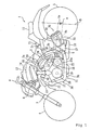
Fig. 1 is a side view of a motorcycle that is provided with an exhaust system according to an embodiment of the invention. -
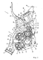
Fig. 2 is a side view showing a state in which an engine, to which the exhaust system is connected, is mounted to a vehicle body frame. -
Fig. 3 is a side view of the exhaust system. -
Fig. 4 is a plan view of the exhaust system. -
Fig. 5 is a plan view of an exhaust gas chamber of the exhaust system. -
Fig. 6 is a side view of the exhaust gas chamber. -
Fig. 7 is a cross sectional rear view of the exhaust gas chamber. -
Fig. 8 is a plan view of a muffler of the exhaust system. -
Fig. 9 is a side view of the muffler. -
Fig. 10 is a cross sectional view of the muffler. -
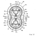
Fig. 11 is a cross sectional view of a tail cap of the muffler. -
Fig 12 is a rear view of the tail pipe. - Hereinafter, an embodiment of the invention will be described with reference to the appended drawings, in which
-
Fig. 1 to Fig. 12 are figures that illustrate an exhaust system for a motorcycle according to the embodiment of the invention. Note that, the terms front and rear, and left and right as used in this embodiment indicate the front and rear and the left and right when viewed from a rider seated on a seat. - As shown in the figures, a
motorcycle 1 includes a twin sparvehicle body frame 2, an engine 3 that is mounted on thevehicle body frame 2, and afront wheel 4, and arear wheel 5 that are disposed at the front and rear of thevehicle body frame 2. - The
vehicle body frame 2 includes ahead pipe 6 that is disposed at the front end of thevehicle body frame 2; left and rightmain frames 2a that extend diagonally downward toward the rear while expanding outwards to the left and right from thehead pipe 6; left and rightrear frames 2b that are contiguous with themain frames 2a and that extend and curve downwards; and left andright seat rails 2c that extend diagonally upward to the rear from therear frames 2b. - A
front fork 7 is turnably supported by thehead pipe 6 so as to be capable of being steered to the left and right. Thefront wheel 4 is rotatably supported by a lower end section of thefront fork 7, and asteering handle 8 is fixed to an upper end section of thefront fork 7. - A front end section of a
rear arm 9 is pivotably supported via apivot shaft 10 at a lower end section of the left and rightrear frames 2b such that therear arm 9 is capable of swinging upward and downward. Therear wheel 5 is pivotably supported by a rear end section of therear arm 9. - A straddle type
main seat 11, a straddletype tandem seat 12 that is positioned to the rear side of themain seat 11 are mounted on the left andright seat rails 2c. Atank cover 13, which is an exterior part, is disposed to the front side of themain seat 11. - The engine 3 is a four stroke, four cylinder V-type engine that has left and right front side cylinders and left and right rear side cylinders that are disposed to form a V-shaped banks. An engine upper section is supported by and suspended from left and
right suspension brackets main frames 2a, and an engine rear wall is supported in a suspended manner by asuspension bracket 15a fixed to therear frames 2b etc. - The engine 3 has a structure in which a
crank case 20 that houses acrank shaft 19 is connected to lower mating surfaces of front andrear cylinder blocks rear cylinder blocks rear cylinder heads rear cylinder heads - A
transmission case 20a that houses a change gear mechanism (not shown) is formed to be integrally connected with a rear side of thecrank case 20. An upper wall and a lower wall of thetransmission case 20a are fixed by tightened bolts to therear frames 2b. Note that, 25 is an engine force output shaft. - An
intake system 29 of the engine 3 is provided with left and right front side and rearside intake pipes side intake pipes rear cylinder heads side intake pipes - The air cleaner is disposed beneath the
tank cover 13 between the left and rightmain frames 2a, and the left and right front side and rearside intake pipes right intake ducts tank cover 13. The left andright intake ducts 14 communicate with the air cleaner. - An
exhaust system 30 of the engine 3 includes fourexhaust pipes 31 connected to the engine 3, a singleexhaust gas chamber 32 connected to theexhaust pipe 31, and left andright mufflers exhaust gas chamber 32. More specifically, theexhaust system 30 has the following structure. - The
exhaust pipe 31 includes left and right lateral exhaust pipes (engine side exhaust pipes) 34, 34, left and right vertical exhaust pipes (engine side exhaust pipes) 35, 35, downstreamside exhaust pipes tail pipes lateral exhaust pipes front cylinder head 21. The left and rightvertical exhaust pipes cylinder head 22. The downstreamside exhaust pipes exhaust gas chamber 32, and thetail pipes side exhaust pipes - The left and right
lateral exhaust pipes 34 include adownward slanting section 34a, ahorizontal section 34b, and a horizontalcurved section 34c. Thedownward slanting section 34a protrudes outwards toward the vehicle width direction outer side from thecylinder head 21 while extending downwards. Thehorizontal section 34b extends generally linearly to the rear from a lower end of theslanting section 34a along a lower side of thecrank case 20. The horizontalcurved section 34c curves and extends in the vehicle width direction inner side from a rear end of thehorizontal section 34b. The pair of left and righthorizontal sections 34b are connected and communicate with each other via acommunication pipe 36 that extends in the vehicle width direction. - The left and right
vertical exhaust pipes 35 include a verticalcurved section 35a, and aperpendicular section 35b. The verticalcurved section 35a curves and extends downwards to the rear side of thetransmission case 20a from thecylinder head 22. Theperpendicular section 35b is contiguous with the verticalcurved section 35a and extends downwards in a generally linear manner. - The
exhaust gas chamber 32 is disposed between thetransmission case 20a of the engine 3 and therear wheel 5, and below therear arm 9 including thepivot shaft 10. Theexhaust gas chamber 32 has afront flange 32a that is formed to protrude outwards at a front end of theexhaust gas chamber 32, and left andright flanges exhaust gas chamber 32. Thefront flange 32a is attached to the crankcase 20, and the left andright flanges rear frame 2b via a bracket, not shown. - The
exhaust gas chamber 32 includes achamber body 37, first, second and third expansion chambers a to c, a first communicatingpassage 39, and a second communicatingpassage 40. Thechamber body 37 is a sealed box that is formed by joining respective outer periphery edge sections of anupper member 37a and alower member 37b. The first, second and third expansion chambers a to c are defined by first andsecond partition walls chamber body 37. Thefirst communication passage 39 communicates between the first expansion chamber a and the second expansion chamber b. The second communicatingpassage 40 communicates between the second expansion chamber b and the third expansion chamber c. - The first to third expansion chambers a to c are arranged from the front side in the order of the first expansion chamber a, the third expansion chamber c, the second expansion chamber b. When viewed from the flow direction of the exhaust gas, the second expansion chamber b is positioned between the first expansion chamber a to which the left and right
lateral exhaust pipes 34 and the left and rightvertical exhaust pipes 35 are connected, and the third expansion chamber c to which the left andright mufflers 33 are connected. - The volume of the first expansion chamber a is set to be larger than the volume of the second and the third expansion chambers b, c, and the volume of the second expansion chamber b is set to be larger than the volume of the third expansion chamber c.
- The
chamber body 37, when viewed from above, has a generally hexagonal shape, and includes afront end wall 37c; left and rightfront slanting walls front end wall 37c; left andright side walls front slanting walls 37d; and arear wall 37f that extends in the vehicle width direction to connect between respective rear ends of the left andright side walls 37e. - The horizontal
curved sections lateral exhaust pipes 34 are connected to the left and rightfront slanting walls 37d of thechamber body 37 so as to communicate with the first expansion chamber a. As a result, exhaust gas flowing through the left and rightlateral exhaust pipes 34 flows in to the first expansion chamber a from the outside in the vehicle width direction toward the inside in the vehicle width direction. - In addition, the right
lateral exhaust pipe 34 includes an extendingsection 34d that is contiguous with the horizontalcurved section 34c and extends towards a central portion within the first expansion chamber a. The extendingsection 34d is positioned so as to open in the first expansion chamber a to the rear side of the left and rightvertical exhaust pipes 35. The opening of the extendingsection 34d is in a central portion in the vehicle width direction of both of theexhaust pipes 35. - The
perpendicular sections vertical exhaust pipes front end wall 37c of thechamber body 37 so as to communicate with the first expansion chamber a. Accordingly, exhaust gas flowing through the left and rightvertical exhaust pipes 35 flows within the first expansion chamber a from the upper side in the upward-downward direction toward the downward side in the upward-downward direction. - A
boss 37h is formed in a vehicle width direction inside end portion of anupper wall 37g of thechamber body 37 so as to communicate with the first expansion chamber a. Adetection member 42a of an oxygenconcentration detection sensor 42 is inserted in theboss 37h so as to be positioned within the first expansion chamber a. The oxygenconcentration detection sensor 42 is surrounded by thechamber body 37, the left and rightrear frames 2b, thepivot shaft 10, and therear arm 9, and is thereby inhibited from being damaged by external forces. - The oxygen
concentration detection sensor 42 is disposed at a position inside the first expansion chamber a that is away from a merging portion A of the left and rightlateral exhaust pipes 34 and the left and rightvertical exhaust pipes 35. More specifically, the extendingsection 34d is disposed such that exhaust gas is led away from the oxygenconcentration detection sensor 42. In addition, the structure is configured such that exhaust gas from each exhaust pipe is mixed together, and the mixed gas is brought into contact with thedetection member 42a of the oxygenconcentration detection sensor 42. - The first communicating
passage 39 is disposed so as to pass through the first andsecond partition walls passage 39, when viewed from above, is disposed at the opposite side of thechamber body 37 from the oxygenconcentration detection sensor 42, and an exhaustgas inflow port 39a of thefirst communication passage 39 is disposed in the vicinity of the exhaust gas merging portion A of the first expansion chamber a. - A
catalyst 43 is disposed in thefirst communication passage 39. Thecatalyst 43 has a structure in which a honeycombstructure catalyst body 43b that purifies exhaust gas is disposed inside ametal tubular body 43a that forms the communicatingpassage 39. - The
catalyst 43 has an elliptical shape when viewed in a cross section, and is disposed such that the long axis of the elliptical shape extends in the vehicle width direction (refer toFIG. 7 ). - The second communicating
passage 40 is structured to pass through thesecond partition wall 38b and to connect the second expansion chamber b and the third expansion chamber c. Further, the second communicatingpassage 40 is disposed in the vicinity of theright side wall 37e of thechamber body 37. The second communicatingpassage 40 is disposed in alignment with thefirst communication passage 39 to the right side thereof, and the exhaustgas inflow port 40a of the second communicatingpassage 40 is disposed at a position that is offset in the vehicle width direction from an exhaustgas outflow port 39b of thefirst communication passage 39. - Exhaust gas from each cylinder passes along the left and right
lateral exhaust pipes 34 and the left and rightvertical exhaust pipes 35, and flows in to the first expansion chamber a of theexhaust gas chamber 32. The exhaust gas, which merges together in the first expansion chamber a, flows in to the second expansion chamber b via thecatalyst 43 of thefirst communication passage 39. The exhaust gas then passes from the second expansion chamber b to the second communicatingpassage 40, and flows in to the third expansion chamber c. Then, the exhaust gas flows from the third expansion chamber c through the left andright mufflers 33 and is exhausted to the outside. - A variable
passage area valve 45 is disposed in the second communicatingpassage 40 and is structured so at to be capable of adjusting the passage area of the communicatingpassage 40. - The variable
passage area valve 45 includes a communicatingpipe 45a, avalve shaft 45b, and avalve plate 45c. The communicatingpipe 45a has a tubular shape and forms the second communicatingpassage 40. Thevalve shaft 45b is disposed to pass through the communicatingpipe 45a in the vehicle width direction, and thevalve plate 45c is fixed to thevalve shaft 45b so as to be disposed within the communicatingpipe 45a. - The
valve shaft 45b is disposed to extend in the vehicle width direction, and a right end section passes through theright side wall 37e of thechamber body 37 and protrudes in the outward direction. A drivenpulley 46 is fitted to a protrudingportion 45d of thevalve shaft 45b. The drivenpulley 46 is connected to a drivepulley 49 that is fitted to a rotating shaft of adrive motor 48 via acable 47. Thedrive motor 48 is disposed inside aside cover 50 at the lower side of the seat rails 2c. - The variable
passage area valve 45 is controlled to open and close by a controller, not shown. The controller detects an engine operation state based on an engine speed, engine load and the like. When the engine operation state is in a low speed region, the controller controls the variablepassage area valve 45 to close, and when the engine operation state is in a middle or high speed region, the controller controls the variablepassage area valve 45 to open. - The left and
right mufflers 33 includemuffler bodies side exhaust pipes right side walls exhaust gas chamber 32 so as to communicate with the third expansion chamber c. - The left and
right mufflers 33, as shown inFIG. 1 , are disposed further to the front than a vertical line B that passes through a centre x of arotation shaft 5a of therear wheel 5. In addition, the left andright mufflers 33 are disposed such that respective front-rear direction centres D thereof are positioned in the vicinity of afront edge 5b of therear wheel 5. - The left and
right mufflers 33 are disposed to extend diagonally upward to the rear from theexhaust gas chamber 32, and also protrude toward the outside in the vehicle width direction. - The left and
right muffler bodies 33b have acasing 52 and atail cap 53. Thecasing 52 is formed to surround an outer periphery of thetail pipes 51 connected to the downstreamside exhaust pipes 33a. Thetail cap 53 is attached so as to cover the outer side of arear end wall 52a of thecasing 52. - The
tail pipes 51 include: a singlemain pipe 51a that is connected and fixed in an attachable-detachable manner to the downstreamside exhaust pipes 33a via afastening member 55; and first andsecond branch pipes main pipe 51a and fork upward and downward while extending to the rear. The first andsecond branch pipes main pipe 51a. - As shown in
FIG. 10 andFIG. 11 , thesecond branch pipe 51c to the lower side is formed to be linear and has an axis line C2 that extends generally parallel with an axis line C of themain pipe 51a. On the other hand, thefirst branch pipe 51b to the upper side is formed to curve downward toward thesecond branch pipe 51c side. As a result, the length of the exhaust pipe of thefirst branch pipe 51b is slightly longer than the length of thesecond branch pipe 51c. - In addition, the
first branch pipe 51b is formed such that a rearward extension line of an axis line C1 thereof intersects with a rearward extension line of the axis line C2 of thesecond branch pipe 51c. Accordingly, when viewed when themufflers 33 are mounted, anexhaust port 51c' of thesecond branch pipe 51c slopes upwards, while anexhaust port 51b' of thefirst branch pipe 51b slopes relatively downwards. - An
attachment bracket 52d is fixed to an upper wall surface of thecasing 52. Theattachment bracket 52d is attached in an attachable-detachable manner to the seat rails 2c via a stay member and the like. - A front end opening of the
casing 52 is closed by afront end wall 52b, and a rear end opening of thecasing 52 is closed by arear end wall 52a. A pair of up-down brackets 52a' are fixed to therear end wall 52a. Each of thebrackets 52a' includes acap attachment seat 52f that has a disc like shape when viewed from the vehicle rear direction, and a plurality oflegs 52f' that extend from theattachment seat 52f toward therear end wall 52a. Thelegs 52f' are fixed by welding to therear end wall 52a. - Note that, the exhaust ports (rear end surfaces) 51b', 51c' of the first and
second branch pipes rear end wall 52a and are disposed to form a generally flush surface with thecap attachment seats brackets 52a' and an opening edge f oftail holes 61c, described later. More specifically, theexhaust ports 51b', 51c' of the first andsecond branch pipes tail holes - The
main pipe 51a passes through thefront end wall 52b to the front, and is joined to thefront end wall 52b in an air tight manner. The first andsecond branch pipes rear end wall 52a to the rear, and are joined to therear end wall 52a in an air tight manner. - The
casing 52 is an elliptically shaped cylinder that is formed to have an elliptical shape when viewed in a cross section, and a cross sectional area that increases from the upstream side to the downstream side when viewed from the exhaust gas flow direction. In addition, themufflers 33 are disposed to incline diagonally upward to the vehicle rear such that a long axis h of the ellipse extends generally in the upward-downward direction. - Recessed
portions outer side walls casing 52. As a result, thecasing 52 has a generally gourd like shape in which two circular sections partially overlap when viewed in a cross section. - An
exterior cover 57 that covers the outer side of the downstreamside exhaust pipes 33a is provided between thecasing 52 and theexhaust gas chamber 32. Theexterior cover 57 is contiguous with thecasing 52 and has a pointed shape that becomes more pointed as theexterior cover 57 extends toward the upstream side (the lower side). Theexterior cover 57 forms a section of thecasing 52. - The inside of the
casing 52 is filled withsound absorbing material 56 like glass wool such that thetail pipes 51 are surrounded. A plurality ofsmall holes 51d are formed around the entire periphery of themain pipe 51a. A portion of the exhaust gas flows in to thecasing 52 through thesmall holes 51d, and exhaust noise of the exhaust gas is absorbed by thesound absorbing material 56. - The
tail cap 53 is constructed by two parts, namely, anouter cap 60 and aninner cap 61. Theouter cap 60 has a ring shape that is formed to surround arear end edge 52g of thecasing 52. Theinner cap 61 is disposed so as to surround therear end wall 52a of thecasing 52. - The
inner cap 61 includes acap body 61a that surrounds therear end wall 52a of thecasing 52, and aflange 61b that protrudes from an outer periphery edge g of thecap body 61a and extends outwards to the rear. - The tail holes 61c, 61c, which are provided as an upward and downward pair, are formed in the
cap body 61a. Each one of thetail holes 61c is formed to have a larger diameter than theexhaust ports 51b', 51c' of the first andsecond branch pipes branch pipes tail holes 61c. - A pair of upward and downward expanding
sections cap body 61a. The tail holes 61c are formed in a central section of the expandingsections 61d. - Three bolts (fixing members) 63 are positioned at determined distances apart in the circumferential direction in an outer periphery of the upward and downward expanding
sections 61d. Theinner cap 61 is fixed to thebrackets 52a' by screwing eachbolt 63 to anut 63a that is fixed to thebrackets 52a'. Accordingly, therear end wall 52a is covered by theinner cap 61. In this manner, a disc shaped space e is formed between therear end wall 52a and thetail cap 53 at the rear end section of thecasing 52. - The
outer cap 60 includes a ring shapedsection 60a, aninside slanting section 60b, and abent back section 60c. The ring shapedsection 60a extends along therear end edge 52g of thecasing 52. Theinside slanting section 60b extends diagonally to the inside rear from the ring shapedsection 60a. Thebent back section 60c curves and extends to the inside from theinside slanting section 60b. The ring shapedsection 60a is fixed to therear end edge 52g by rivets (fixing members) 64 that are disposed at determined distances apart in the circumferential direction. - Note that, the bent back
section 60c is formed to bend around from the outside to the inside of anouter periphery edge 61b' of theflange 61b of theinner cap 61 so as to cover theouter periphery edge 61b' . As a result, a gap s is formed at the boundary region between theflange 61b and the bent backsection 60c. The gap s and the gap s' around thebranch pipes rear end wall 52a of thecasing 52 and theouter cap 60 and theinner cap 61. In addition, the gap s also communicates with the outside space. Accordingly, the gap s forms a passage that extends from the space e to the outside space. - According to the exhaust system of the embodiment, the first and
second branch pipes tail pipes 51 are disposed such that the rear end surfaces 51b', 51c' thereof are generally flush with the opening edge f of the tail holes 61c of thecap body 61a, namely, such that the rear end surfaces are to the inside of thetail cap 53. Thus, it is possible to improve saleability of themufflers 33 by improving its external appearance. - Moreover, in the structure in which the rear end surfaces are disposed to the inside of the
tail cap 53, thetail cap 53 has a two piece structure including the ring shapedouter cap 60 that is fixed to therear end edge 52g of thecasing 52 and theinner cap 61 fixed to therear end wall 52a of thecasing 52. Accordingly, the gap s is formed in the boundary region between theinner cap 61 and theouter cap 60. If exhaust gas that enters/exits to/from the upper and lower first andsecond branch pipes tail cap 53 and therear end wall 52a of thecasing 52 from the gap s' between thebranch pipes tail holes 61c, the trapped exhaust gas is exhausted from the gap (passage) s of the boundary region. Accordingly, the space e does not form a resonance chamber, and it is possible to inhibit the generation of flow noise. - Moreover, because the gap s of the
tail cap 53 is provided at the boundary region of theouter cap 60 and theinner cap 61, the gap s cannot be seen from the rear of the motorcycle. Accordingly, external appearance is not worsened. In the structure in which the gap s is formed, theflange 61b of thecap body 61a is covered by the bent backsection 60c of theouter cap 60 that bends around from the outside to the inside. Therefore, it is possible to reliably inhibit the gap s from being seen from the outside, and create a structure in which theouter cap 60 and theinner cap 61 appear to be integrated from the outside. - In addition, because the
tail cap 53 has a two part structure including theouter cap 60 and theinner cap 61, the gap s is ensured and it is easily possible to provide a structure in which the gap s is not visible from the outside. Thus, the degree of design freedom can be increased. - This embodiment adopts a structure in which the ring shaped
section 60a of theouter cap 60 is fixed to therear end edge 52g of thecasing 52 by therivet 64, and thecap body 61a of theinner cap 61 is fixed to therear end wall 52a of thecasing 52 by thebolt 63 that is screwed in from the rear side. As a result, thetail cap 53 can be attached simply. - In this embodiment, the
tail pipes 51 include themain pipe 51a connected to theexhaust gas chamber 32, and the first andsecond branch pipes main pipe 51a that branches upward and downward. Thus, a simple structure is provided that can create the external appearance that the motorcycle has two protruding mufflers when the vehicle is viewed from the rear. Thus, the saleability can be improved by improving the external appearance of themufflers 33. - Moreover, the recessed
portions 52e that are formed in a concave shape extend in the longitudinal direction in the upward-downward direction central portion of the outer andinner side walls casing 52. Accordingly, it is possible to create the external appearance that the motorcycle has two protruding mufflers when the vehicle is viewed from the side, and this feature also promotes saleability by improving the external appearance of themufflers 33. - Because the
sound absorbing material 56 fills the inside of thecasing 52 so as to surround thetail pipes 51, and the plurality ofsmall holes 51d are formed in themain pipe 51a, the exhaust pipe length of themufflers 33 can be reduced, and exhaust noise can be reduced. - In this embodiment, the
casing 52 is formed to be an elliptically shaped cylinder that expands from the upstream side to the downstream side, and the long axis h of the ellipse extends generally in the upward-downward direction. Thus, an external appearance is created that conveys an impression of strength not achieved up to now. - Because the left and
right mufflers 33 are disposed to extend diagonally upward to the rear, and protrude to the outside in the vehicle width direction, it is possible to create an external appearance that conveys an even more powerful impression of strength. - Since the left and
right mufflers 33 are disposed to the front side of the vertical line B that passes through therotation shaft 5a of therear wheel 5, it is possible to create an external appearance that conveys an impression of strength not achieved up to now. Moreover, the mass can be concentrated. - In this embodiment, the
exhaust pipe 31 connected to the engine 3 is connected to the first expansion chamber a of theexhaust gas chamber 32, and themufflers 33 are connected to the third expansion chamber c of theexhaust gas chamber 32, and, when viewed from the exhaust gas flow direction, the second expansion chamber b is disposed between the first expansion chamber a and the third expansion chamber c. Accordingly, it is possible to provide three expansion chambers without increasing the size of theexhaust gas chamber 32, in effect extend exhaust pipe length, and improve exhaust gas sound absorbing effect. - Note that, this embodiment explains an example in which the
tail pipes 51 include the first andsecond branch pipes -
- 1
- Motorcycle
- 3 4
- Cylinder V-Type Engine
- 5
- Rear Wheel
- 5a
- Rotation Shaft
- 30
- Exhaust System
- 31
- Exhaust Pipe
- 32
- Exhaust Gas Chamber
- 33
- Muffler (or silencer)
- 34, 35
- Lateral, Vertical Exhaust Pipes (Engine Side Exhaust Pipes)
- 51
- Tail Pipe (Rear Section Of Exhaust Pipe)
- 51a
- Main Pipe
- 51b, 51c
- First And Second Branch Pipes
- 51b', 51c'
- Rear End Surfaces Of Tail Pipe
- 51d
- Hole
- 52
- Casing
- 52a
- Rear End Wall
- 52e
- Recessed Portion
- 52g
- Rear End Edge
- 53
- Tail Cap
- 56
- Sound Absorbing Material
- 60
- Outer Cap
- 60c
- Bent Back Section
- 61
- Inner Cap
- 61a
- Cap Body
- 61b
- Flange
- 61c
- Tail Hole
- 63
- Bolt (Fixing Member)
- 64
- Rivet (Fixing Member)
- a, b, c
- First, Second And Third Expansion Chambers
- B
- Vertical Line
- e
- Space
- f
- Opening Edge Of Tail Hole
- g
- Outer Periphery Edge Of Cap Body
- h
- Long Axis
- s
- Gap (Passage)
- s'
- Gap
- x
- Rear Wheel Rotation Centre
Claims (18)
- An exhaust system (30) for a motorcycle (1) including an exhaust pipe to be connected to an engine (3) and a muffler (33) connected to the exhaust pipe (31), wherein
the muffler includes a casing (52), provided in a rear end section of the muffler, that has a rear end wall and that is formed to surround a rear section (51) of the exhaust pipe, and a tail cap (53) that is disposed to surround an outer side of the rear end wall of the casing, and
a tail hole is formed in the rear end wall such that a gap is left with respect to an outer diameter of an end portion of the rear section of the exhaust pipe, the gap between the tail hole and the end portion of the rear section of the exhaust pipe is in communication with a space formed between the rear end wall and the tail cap, and a passage is formed that communicates the space and an outside space. - The exhaust system for a motorcycle according to claim 1, wherein the exhaust pipe includes an engine side exhaust pipe that is connected to the engine, and a tail pipe that is connected to the engine side exhaust pipe and that is surrounded by the casing.
- The exhaust system for a motorcycle according to claim 2, wherein the tail cap includes a ring shaped outer cap that is attached to an outer side of the rear end wall of the casing, and an inner cap which is attached to the rear end wall of the casing and in which the tail hole is formed such that a gap is left with respect to the outer diameter of the tail pipe, and wherein the passage is the gap formed in a boundary region between the inner cap and the outer cap.
- The exhaust system for a motorcycle according to claim 3, wherein the tail pipe is formed such that a rear end surface of the tail pipe is generally flush with an opening edge of the tail hole of the inner cap.
- The exhaust system for a motorcycle according to claim 3 or claim 4, wherein the inner cap includes a cap body that is fixed to the rear end wall of the casing and in which the tail hole is formed, and a flange that protrudes outward to the rear from an outer periphery edge of the cap body, and the outer cap includes a bent back section that bends around from an outer side to an inner side of the flange, and a gap is formed between the bent back section and the flange.
- The exhaust system for a motorcycle according to any of claims 3 to 5, wherein the outer cap is fixed to a rear end edge of the casing by a fixing member.
- The exhaust system for a motorcycle according to any fo claims 3 to 6, wherein the inner cap is fixed from the rear to the rear end wall of the casing by a fixing member.
- The exhaust system for a motorcycle according to any of claims 3 to 7, wherein the tail pipe includes a main pipe connected to the engine side exhaust pipe and that extends to the rear, and a first branch pipe and a second branch pipe that are connected to the main pipe and that branch out from the main pipe.
- The exhaust system for a motorcycle according to claim 8, wherein sound absorbing material is filled in an area between the casing and the tail pipe.
- The exhaust system for a motorcycle according to claim 9, wherein a hole is formed in the main pipe.
- The exhaust system for a motorcycle according to any preceding claim, wherein the casing has an elliptical shape when viewed in a cross section, and is formed such that, when viewed from an exhaust gas flow direction, a cross sectional area of the casing becomes larger as the casing extends from an upstream side to a downstream side thereof.
- The exhaust system for a motorcycle according to any preceding claim, characterized in that an exhaust gas chamber is connected to the exhaust pipe, the exhaust gas chamber is partitioned in to a plurality of expansion chambers, and the muffler is connected to one of the expansion chambers.
- The exhaust system for a motorcycle according to claim 12, wherein the exhaust gas chamber includes a first expansion chamber that is connected to the engine side exhaust pipe, a third expansion chamber that is connected to the muffler, and a second expansion chamber that is positioned between the first expansion chamber and the third expansion chamber when viewed from an exhaust gas flow direction.
- A motorcycle including an engine and an exhaust system according to any preceding claim connected to the engine.
- The motorcycle according to claim 14, wherein the casing is shaped as an ellipse when viewed in a cross section, and is disposed such that a long axis of the ellipse extends in a generally upward-downward direction.
- The motorcycle according to claim 15, wherein a recessed portion that extends in an exhaust gas flow direction is formed in an upward-downward direction central portion of the casing.
- The motorcycle according to any of claims 14 to 16, wherein the muffler is disposed to the front of a vertical line that passes through a rotational centre of a rear wheel.
- The motorcycle according to claim 17, wherein the muffler is disposed to extend diagonally upward toward the rear and to protrude outwards in a vehicle width direction outer side.
Applications Claiming Priority (1)
| Application Number | Priority Date | Filing Date | Title |
|---|---|---|---|
| JP2006294139A JP2008111356A (en) | 2006-10-30 | 2006-10-30 | Gas exhaust system of motorcycle and motorcycle equipped with the gas exhaust system |
Publications (2)
| Publication Number | Publication Date |
|---|---|
| EP1921285A1 EP1921285A1 (en) | 2008-05-14 |
| EP1921285B1 true EP1921285B1 (en) | 2009-09-16 |
Family
ID=38983459
Family Applications (1)
| Application Number | Title | Priority Date | Filing Date |
|---|---|---|---|
| EP07254171A Not-in-force EP1921285B1 (en) | 2006-10-30 | 2007-10-22 | Motorcycle exhaust system and motorcycle provided with exhaust system |
Country Status (5)
| Country | Link |
|---|---|
| US (1) | US20080116004A1 (en) |
| EP (1) | EP1921285B1 (en) |
| JP (1) | JP2008111356A (en) |
| AT (1) | ATE443201T1 (en) |
| DE (1) | DE602007002458D1 (en) |
Families Citing this family (6)
| Publication number | Priority date | Publication date | Assignee | Title |
|---|---|---|---|---|
| JP5431100B2 (en) * | 2009-10-02 | 2014-03-05 | 川崎重工業株式会社 | Motorcycle |
| DE102010019959A1 (en) * | 2010-05-08 | 2011-11-10 | J. Eberspächer GmbH & Co. KG | silencer |
| US8430198B2 (en) * | 2010-12-20 | 2013-04-30 | Kawasaki Jukogyo Kabushiki Kaisha | Muffler mounting structure of vehicle and straddle-type four-wheeled vehicle provided with the same |
| JP5637056B2 (en) * | 2011-04-20 | 2014-12-10 | スズキ株式会社 | Muffler for internal combustion engine |
| BR112018016652A2 (en) * | 2016-03-17 | 2018-12-26 | Honda Motor Co., Ltd. | exhaust device for internal combustion engine |
| JP7178231B2 (en) * | 2018-10-01 | 2022-11-25 | カワサキモータース株式会社 | scarf |
Family Cites Families (9)
| Publication number | Priority date | Publication date | Assignee | Title |
|---|---|---|---|---|
| JP2719933B2 (en) * | 1988-08-30 | 1998-02-25 | ヤマハ発動機株式会社 | Motorcycle muffler |
| JP3406176B2 (en) * | 1997-03-25 | 2003-05-12 | 本田技研工業株式会社 | Exhaust system for vehicles |
| DE19914426C2 (en) * | 1999-03-30 | 2003-04-17 | Daimler Chrysler Ag | Double-walled tailpipe for an exhaust pipe of an exhaust system of a motor vehicle |
| JP2001073758A (en) * | 1999-08-31 | 2001-03-21 | Yamaha Motor Co Ltd | Muffler of two-wheeled vehicle |
| JP2001303925A (en) * | 2000-04-21 | 2001-10-31 | Taiwan Sanyo Kisha Kogyo Kofun Yugenkoshi | Muffler structure for motor cycle |
| JP3802803B2 (en) * | 2001-12-19 | 2006-07-26 | 本田技研工業株式会社 | Vehicle exhaust system |
| JP4429826B2 (en) * | 2004-07-02 | 2010-03-10 | 本田技研工業株式会社 | Muffler equipment |
| JP2007008442A (en) * | 2005-03-11 | 2007-01-18 | Yamaha Motor Co Ltd | Motorcycle exhaust system |
| JP2008111357A (en) * | 2006-10-30 | 2008-05-15 | Yamaha Motor Co Ltd | Gas exhaust system of motorcycle |
-
2006
- 2006-10-30 JP JP2006294139A patent/JP2008111356A/en not_active Withdrawn
-
2007
- 2007-10-22 AT AT07254171T patent/ATE443201T1/en not_active IP Right Cessation
- 2007-10-22 EP EP07254171A patent/EP1921285B1/en not_active Not-in-force
- 2007-10-22 DE DE602007002458T patent/DE602007002458D1/en not_active Expired - Fee Related
- 2007-10-29 US US11/927,313 patent/US20080116004A1/en not_active Abandoned
Also Published As
| Publication number | Publication date |
|---|---|
| ATE443201T1 (en) | 2009-10-15 |
| DE602007002458D1 (en) | 2009-10-29 |
| US20080116004A1 (en) | 2008-05-22 |
| EP1921285A1 (en) | 2008-05-14 |
| JP2008111356A (en) | 2008-05-15 |
Similar Documents
| Publication | Publication Date | Title |
|---|---|---|
| EP1921286B1 (en) | Exhaust system for motorcycle | |
| JP5985639B2 (en) | Intake duct for saddle type vehicles | |
| JP4545624B2 (en) | Steering damper mounting structure | |
| EP1918539B1 (en) | Exhaust system for motorcycle and motorcycle including an exhaust system | |
| US7331322B2 (en) | Intake duct structure | |
| US9669704B2 (en) | Air intake structure for saddle-ride type vehicle | |
| US7699134B2 (en) | Motorcycle exhaust system | |
| EP1921285B1 (en) | Motorcycle exhaust system and motorcycle provided with exhaust system | |
| JP4986603B2 (en) | Motorcycles and tricycles | |
| JP3154342U (en) | Motorcycle | |
| US7584814B2 (en) | Motorcycle | |
| US7913796B2 (en) | Exhaust system for motorcycle and motorcycle | |
| JP7252092B2 (en) | Exhaust system | |
| JP4787065B2 (en) | Vehicle fuel tank support structure | |
| JP6392596B2 (en) | Engine exhaust system | |
| JP2010105641A (en) | Saddle riding type vehicle | |
| JP2000248925A (en) | Exhaust device structure | |
| JP4764206B2 (en) | Vehicle rear cushion unit mounting structure | |
| JP4787049B2 (en) | Arrangement structure of vehicle air cleaner |
Legal Events
| Date | Code | Title | Description |
|---|---|---|---|
| PUAI | Public reference made under article 153(3) epc to a published international application that has entered the european phase |
Free format text: ORIGINAL CODE: 0009012 |
|
| AK | Designated contracting states |
Kind code of ref document: A1 Designated state(s): AT BE BG CH CY CZ DE DK EE ES FI FR GB GR HU IE IS IT LI LT LU LV MC MT NL PL PT RO SE SI SK TR |
|
| AX | Request for extension of the european patent |
Extension state: AL BA HR MK RS |
|
| 17P | Request for examination filed |
Effective date: 20080814 |
|
| 17Q | First examination report despatched |
Effective date: 20080919 |
|
| AKX | Designation fees paid |
Designated state(s): AT BE BG CH CY CZ DE DK EE ES FI FR GB GR HU IE IS IT LI LT LU LV MC MT NL PL PT RO SE SI SK TR |
|
| GRAP | Despatch of communication of intention to grant a patent |
Free format text: ORIGINAL CODE: EPIDOSNIGR1 |
|
| GRAS | Grant fee paid |
Free format text: ORIGINAL CODE: EPIDOSNIGR3 |
|
| GRAA | (expected) grant |
Free format text: ORIGINAL CODE: 0009210 |
|
| AK | Designated contracting states |
Kind code of ref document: B1 Designated state(s): AT BE BG CH CY CZ DE DK EE ES FI FR GB GR HU IE IS IT LI LT LU LV MC MT NL PL PT RO SE SI SK TR |
|
| REG | Reference to a national code |
Ref country code: GB Ref legal event code: FG4D |
|
| REG | Reference to a national code |
Ref country code: CH Ref legal event code: EP |
|
| REG | Reference to a national code |
Ref country code: IE Ref legal event code: FG4D |
|
| REF | Corresponds to: |
Ref document number: 602007002458 Country of ref document: DE Date of ref document: 20091029 Kind code of ref document: P |
|
| PG25 | Lapsed in a contracting state [announced via postgrant information from national office to epo] |
Ref country code: SE Free format text: LAPSE BECAUSE OF FAILURE TO SUBMIT A TRANSLATION OF THE DESCRIPTION OR TO PAY THE FEE WITHIN THE PRESCRIBED TIME-LIMIT Effective date: 20090916 Ref country code: FI Free format text: LAPSE BECAUSE OF FAILURE TO SUBMIT A TRANSLATION OF THE DESCRIPTION OR TO PAY THE FEE WITHIN THE PRESCRIBED TIME-LIMIT Effective date: 20090916 Ref country code: LT Free format text: LAPSE BECAUSE OF FAILURE TO SUBMIT A TRANSLATION OF THE DESCRIPTION OR TO PAY THE FEE WITHIN THE PRESCRIBED TIME-LIMIT Effective date: 20090916 |
|
| LTIE | Lt: invalidation of european patent or patent extension |
Effective date: 20090916 |
|
| PG25 | Lapsed in a contracting state [announced via postgrant information from national office to epo] |
Ref country code: LV Free format text: LAPSE BECAUSE OF FAILURE TO SUBMIT A TRANSLATION OF THE DESCRIPTION OR TO PAY THE FEE WITHIN THE PRESCRIBED TIME-LIMIT Effective date: 20090916 Ref country code: PL Free format text: LAPSE BECAUSE OF FAILURE TO SUBMIT A TRANSLATION OF THE DESCRIPTION OR TO PAY THE FEE WITHIN THE PRESCRIBED TIME-LIMIT Effective date: 20090916 Ref country code: NL Free format text: LAPSE BECAUSE OF FAILURE TO SUBMIT A TRANSLATION OF THE DESCRIPTION OR TO PAY THE FEE WITHIN THE PRESCRIBED TIME-LIMIT Effective date: 20090916 Ref country code: SI Free format text: LAPSE BECAUSE OF FAILURE TO SUBMIT A TRANSLATION OF THE DESCRIPTION OR TO PAY THE FEE WITHIN THE PRESCRIBED TIME-LIMIT Effective date: 20090916 |
|
| NLV1 | Nl: lapsed or annulled due to failure to fulfill the requirements of art. 29p and 29m of the patents act | ||
| PG25 | Lapsed in a contracting state [announced via postgrant information from national office to epo] |
Ref country code: CY Free format text: LAPSE BECAUSE OF FAILURE TO SUBMIT A TRANSLATION OF THE DESCRIPTION OR TO PAY THE FEE WITHIN THE PRESCRIBED TIME-LIMIT Effective date: 20090916 |
|
| PG25 | Lapsed in a contracting state [announced via postgrant information from national office to epo] |
Ref country code: PT Free format text: LAPSE BECAUSE OF FAILURE TO SUBMIT A TRANSLATION OF THE DESCRIPTION OR TO PAY THE FEE WITHIN THE PRESCRIBED TIME-LIMIT Effective date: 20100118 Ref country code: EE Free format text: LAPSE BECAUSE OF FAILURE TO SUBMIT A TRANSLATION OF THE DESCRIPTION OR TO PAY THE FEE WITHIN THE PRESCRIBED TIME-LIMIT Effective date: 20090916 Ref country code: ES Free format text: LAPSE BECAUSE OF FAILURE TO SUBMIT A TRANSLATION OF THE DESCRIPTION OR TO PAY THE FEE WITHIN THE PRESCRIBED TIME-LIMIT Effective date: 20091227 Ref country code: CZ Free format text: LAPSE BECAUSE OF FAILURE TO SUBMIT A TRANSLATION OF THE DESCRIPTION OR TO PAY THE FEE WITHIN THE PRESCRIBED TIME-LIMIT Effective date: 20090916 Ref country code: RO Free format text: LAPSE BECAUSE OF FAILURE TO SUBMIT A TRANSLATION OF THE DESCRIPTION OR TO PAY THE FEE WITHIN THE PRESCRIBED TIME-LIMIT Effective date: 20090916 Ref country code: IS Free format text: LAPSE BECAUSE OF FAILURE TO SUBMIT A TRANSLATION OF THE DESCRIPTION OR TO PAY THE FEE WITHIN THE PRESCRIBED TIME-LIMIT Effective date: 20100116 |
|
| PGFP | Annual fee paid to national office [announced via postgrant information from national office to epo] |
Ref country code: FR Payment date: 20091103 Year of fee payment: 3 |
|
| PG25 | Lapsed in a contracting state [announced via postgrant information from national office to epo] |
Ref country code: SK Free format text: LAPSE BECAUSE OF FAILURE TO SUBMIT A TRANSLATION OF THE DESCRIPTION OR TO PAY THE FEE WITHIN THE PRESCRIBED TIME-LIMIT Effective date: 20090916 Ref country code: MC Free format text: LAPSE BECAUSE OF NON-PAYMENT OF DUE FEES Effective date: 20091031 |
|
| PG25 | Lapsed in a contracting state [announced via postgrant information from national office to epo] |
Ref country code: BE Free format text: LAPSE BECAUSE OF FAILURE TO SUBMIT A TRANSLATION OF THE DESCRIPTION OR TO PAY THE FEE WITHIN THE PRESCRIBED TIME-LIMIT Effective date: 20090916 Ref country code: AT Free format text: LAPSE BECAUSE OF FAILURE TO SUBMIT A TRANSLATION OF THE DESCRIPTION OR TO PAY THE FEE WITHIN THE PRESCRIBED TIME-LIMIT Effective date: 20090916 |
|
| PLBE | No opposition filed within time limit |
Free format text: ORIGINAL CODE: 0009261 |
|
| STAA | Information on the status of an ep patent application or granted ep patent |
Free format text: STATUS: NO OPPOSITION FILED WITHIN TIME LIMIT |
|
| PG25 | Lapsed in a contracting state [announced via postgrant information from national office to epo] |
Ref country code: DE Free format text: LAPSE BECAUSE OF NON-PAYMENT OF DUE FEES Effective date: 20100501 Ref country code: DK Free format text: LAPSE BECAUSE OF FAILURE TO SUBMIT A TRANSLATION OF THE DESCRIPTION OR TO PAY THE FEE WITHIN THE PRESCRIBED TIME-LIMIT Effective date: 20090916 |
|
| 26N | No opposition filed |
Effective date: 20100617 |
|
| PG25 | Lapsed in a contracting state [announced via postgrant information from national office to epo] |
Ref country code: GR Free format text: LAPSE BECAUSE OF FAILURE TO SUBMIT A TRANSLATION OF THE DESCRIPTION OR TO PAY THE FEE WITHIN THE PRESCRIBED TIME-LIMIT Effective date: 20091217 Ref country code: IE Free format text: LAPSE BECAUSE OF NON-PAYMENT OF DUE FEES Effective date: 20091022 |
|
| PG25 | Lapsed in a contracting state [announced via postgrant information from national office to epo] |
Ref country code: BG Free format text: LAPSE BECAUSE OF FAILURE TO SUBMIT A TRANSLATION OF THE DESCRIPTION OR TO PAY THE FEE WITHIN THE PRESCRIBED TIME-LIMIT Effective date: 20091031 Ref country code: IT Free format text: LAPSE BECAUSE OF FAILURE TO SUBMIT A TRANSLATION OF THE DESCRIPTION OR TO PAY THE FEE WITHIN THE PRESCRIBED TIME-LIMIT Effective date: 20090916 |
|
| PG25 | Lapsed in a contracting state [announced via postgrant information from national office to epo] |
Ref country code: LU Free format text: LAPSE BECAUSE OF NON-PAYMENT OF DUE FEES Effective date: 20091022 Ref country code: MT Free format text: LAPSE BECAUSE OF FAILURE TO SUBMIT A TRANSLATION OF THE DESCRIPTION OR TO PAY THE FEE WITHIN THE PRESCRIBED TIME-LIMIT Effective date: 20090916 |
|
| PG25 | Lapsed in a contracting state [announced via postgrant information from national office to epo] |
Ref country code: HU Free format text: LAPSE BECAUSE OF FAILURE TO SUBMIT A TRANSLATION OF THE DESCRIPTION OR TO PAY THE FEE WITHIN THE PRESCRIBED TIME-LIMIT Effective date: 20100317 |
|
| PG25 | Lapsed in a contracting state [announced via postgrant information from national office to epo] |
Ref country code: FR Free format text: LAPSE BECAUSE OF NON-PAYMENT OF DUE FEES Effective date: 20101102 |
|
| REG | Reference to a national code |
Ref country code: FR Ref legal event code: ST Effective date: 20110630 |
|
| PG25 | Lapsed in a contracting state [announced via postgrant information from national office to epo] |
Ref country code: TR Free format text: LAPSE BECAUSE OF FAILURE TO SUBMIT A TRANSLATION OF THE DESCRIPTION OR TO PAY THE FEE WITHIN THE PRESCRIBED TIME-LIMIT Effective date: 20090916 |
|
| REG | Reference to a national code |
Ref country code: CH Ref legal event code: PL |
|
| GBPC | Gb: european patent ceased through non-payment of renewal fee |
Effective date: 20111022 |
|
| PG25 | Lapsed in a contracting state [announced via postgrant information from national office to epo] |
Ref country code: CH Free format text: LAPSE BECAUSE OF NON-PAYMENT OF DUE FEES Effective date: 20111031 Ref country code: LI Free format text: LAPSE BECAUSE OF NON-PAYMENT OF DUE FEES Effective date: 20111031 |
|
| PG25 | Lapsed in a contracting state [announced via postgrant information from national office to epo] |
Ref country code: GB Free format text: LAPSE BECAUSE OF NON-PAYMENT OF DUE FEES Effective date: 20111022 |