EP1921232A2 - Non-copyable flat security key and security cylinder - Google Patents
Non-copyable flat security key and security cylinder Download PDFInfo
- Publication number
- EP1921232A2 EP1921232A2 EP07380275A EP07380275A EP1921232A2 EP 1921232 A2 EP1921232 A2 EP 1921232A2 EP 07380275 A EP07380275 A EP 07380275A EP 07380275 A EP07380275 A EP 07380275A EP 1921232 A2 EP1921232 A2 EP 1921232A2
- Authority
- EP
- European Patent Office
- Prior art keywords
- shank
- moving element
- housing
- rotor
- key
- Prior art date
- Legal status (The legal status is an assumption and is not a legal conclusion. Google has not performed a legal analysis and makes no representation as to the accuracy of the status listed.)
- Withdrawn
Links
Images

Classifications
-
- E—FIXED CONSTRUCTIONS
- E05—LOCKS; KEYS; WINDOW OR DOOR FITTINGS; SAFES
- E05B—LOCKS; ACCESSORIES THEREFOR; HANDCUFFS
- E05B27/00—Cylinder locks or other locks with tumbler pins or balls that are set by pushing the key in
-
- E—FIXED CONSTRUCTIONS
- E05—LOCKS; KEYS; WINDOW OR DOOR FITTINGS; SAFES
- E05B—LOCKS; ACCESSORIES THEREFOR; HANDCUFFS
- E05B19/00—Keys; Accessories therefor
- E05B19/0017—Key profiles
-
- E—FIXED CONSTRUCTIONS
- E05—LOCKS; KEYS; WINDOW OR DOOR FITTINGS; SAFES
- E05B—LOCKS; ACCESSORIES THEREFOR; HANDCUFFS
- E05B35/00—Locks for use with special keys or a plurality of keys ; keys therefor
- E05B35/003—Locks for use with special keys or a plurality of keys ; keys therefor for keys with movable bits
Definitions
- the present invention relates to a flat high-security key with a moving element, with a very high combination possibility and a maximum complexity in its reproduction, which makes it virtually non-copyable.
- the mentioned key with a flat shank is reversible and paracentric in relation to the longitudinal axis of the shank of the key.
- the present invention also relates to a security cylinder operable with such a non-copyable security key.
- ES-A-8503771 discloses a key system for lock cylinder having a shank with a flattened profile adapted to be inserted in the slot of a cylindrical rotor which can rotate inside a stator of a cylinder, said shank integrating a plurality of recesses aligned in one of the faces of the key, suitable for being coupled to detecting pins housed in the rotor in contact with locking pins housed in the stator and pushed towards the slot by springs.
- the mentioned key further includes two moving elements assembled in respective housings located in lateral edges or opposite sides of the key. The moving elements are elastically loaded to move within their housings between retracted and extended positions to engage and move respective additional detecting pins housed in the rotor in contact with additional locking pins housed in the stator against the thrust of additional springs.
- GB-A-2277774 discloses a flat key of the type mentioned above in which moving elements are located in through holes inclined in relation to the plane of the key and arranged to make contact at their two opposite ends with respective detecting pins housed in the rotor in contact with corresponding locking pins housed in the stator.
- EP-A-0605932 discloses a flat key of the type mentioned above wherein moving elements are movably housed in respective through bores in the shank and retained therein by respective retaining rings joined to the bores. Each moving element can move perpendicularly to flat faces of the shank between an extended position, wherein one active end of the moving element protrudes from one face of the shank, and a retracted position, wherein the active end of the movable element does not protrude from the one face of the shank and an opposite passive end of the movable element is flush with the opposite face of the shank.
- An actuating pin housed in the rotor and elastically loaded by an actuating spring is arranged to engage the passive end of the movable element of the key shank so as to move the movable element to the extended position, thereby the active end of the movable element engages and moves an additional detecting pin housed in the rotor in contact with an additional locking pin housed in the stator against the thrust of an additional spring.
- US-A-4377082 discloses a flat key based on similar principles than cited EP-A-0605932 wherein balls are used as movable elements in the key shank. The balls are retained within the respective housing through bores by narrowed areas at the ends of the bores.
- the present invention provides a non-copyable flat security key comprising a shank with a flattened profile adapted to be inserted in a slot existing in a cylindrical rotor which can rotate in a cylindrical stator of a cylinder.
- a plurality of recesses are aligned along at least a first face of said shank, which recesses are prepared to engage first detecting pins housed in said rotor in contact with respective first locking pins housed in said stator and pushed towards said slot by first springs.
- At least one moving element is retained in a housing of the shank, which moving element can move between an extended position, in which a conical or frustoconical end of said moving element projects from the shank, and a retracted position, in which the moving element does not project from the shank.
- the mentioned conical or frustoconical end is prepared to engage a second detecting pin housed in the rotor in contact with a corresponding second locking pin housed in the stator and pushed towards the slot by a second spring.
- the moving element is pushed towards its extended position by a third spring arranged in the mentioned housing. This third spring is capable of moving said detecting and locking pins against the thrust of said second spring.
- the key according to the present invention is characterized in that the housing of the moving element is located in said first face of the shank aligned with the plurality of recesses, and the moving element is arranged to move in the housing perpendicular to said first face of the shank so as to push said second detecting and locking pins, which are arranged in parallel and aligned with said first detecting and locking pins in the rotor and the stator, respectively.
- the housing for the moving element is furthermore a blind hole, and the moving element defines a cavity facing a bottom of said blind hole.
- the mentioned third spring is in the form of a helical spring partially housed in said cavity of the moving element and arranged under compression between said bottom of the housing and the moving element.
- a retaining ring joined to the housing prevents the moving element from coming out of the housing.
- the housing with the moving element can be located in any position along the shank of the key, either in any of the two ends of the row of recesses or intercalated between two recesses.
- the moving element and its corresponding detecting pin are further configured to ensure a protection against any attack by the "rebound" system. This system is based on the rebound effect that occurs when a false key is introduced in the slot of the cylinder and it is given a blow in a longitudinal direction. This blow in the key is transmitted to the detecting pins which rebound with the locking pins, separating them and unblocking the cylinder.
- the mentioned flattened profile of the shank is a paracentric profile and has a second face parallel to said first face.
- this second face of the shank there are arranged a second plurality of recesses and a second moving element in a second housing, all of them in positions that are symmetrical to those of the first plurality of recesses and of the first moving element in the first housing in the first face of the shank.
- the key can thus be operatively inserted without distinction in the slot of the cylinder in two symmetrical positions.
- the present invention provides a security cylinder operable with the above non-copyable flat security key, the cylinder being of the type comprising a cylindrical stator and a cylindrical rotor mounted to rotate therein, said cylindrical rotor having a slot configured to receive a flattened profile shank of a key.
- first detecting pins to be put in contact with respective first locking pins housed in said stator.
- Each pair of first detecting and locking pins is pushed towards said slot by a corresponding first spring.
- Said first detecting pins are engageable by a plurality of recesses aligned along at least a first face of said shank of the key.
- a second detecting pin to be put in contact with a corresponding second locking pin housed in the stator and pushed towards the slot by a second spring, said second detecting pin being engageable by an end of at least one moving element retained in a housing of the shank of the key and movable between an extended position, in which said end of said moving element projects from the shank, and a retracted position, in which the moving element does not project from the shank, said second detecting and locking pins being movable against the thrust of said second spring by a third spring arranged in said housing of the key to push the moving element towards its extended position.
- the security cylinder of the invention is characterized in that said first and second detecting pins are arranged parallel to each other and perpendicular to the slot in a same plane at one side of the slot in the rotor, so as to correspond with the positions of the housing of the moving element and the plurality of recesses which are aligned in said first face of the shank of the key, and with a motion of the moving element in the housing being perpendicular to the first face of the shank of the key.
- said first and second locking pins are arranged parallel to each other and perpendicular to the rotation axis of the rotor in a same plane at one side of the rotor in the stator, the first and second detecting pins and the first and second locking pins being located to be correspondingly aligned with each other when the rotor is in a predetermined angular position with respect the stator.
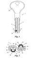
- reference numeral 1 generally designates a non-copyable flat security key according to an exemplary embodiment of the present invention.
- the key comprises a head 22 and a shank 2 with a flattened profile, adapted to be inserted in a slot 3 (see Figure 3 ) existing in a cylindrical rotor 4 which can rotate about a rotation axis in a cylindrical stator 5 of a security cylinder 20.
- the shank 2 has a paracentric profile and defines two opposite flat faces, in which longitudinal channels are formed.
- a plurality of mutually aligned recesses 6 are formed along both faces of the shank 2, which recesses are prepared to engage first detecting pins 7 (see Figure 4 ) housed in cylindrical holes formed in the mentioned rotor 4.
- first detecting pins 7 In a predetermined angular position of the rotor 4 with respect the stator 5, these first detecting pins 7 are in contact with respective locking pins 8 housed in cylindrical holes formed in said stator 5, and the first locking pins 8 are pushed towards said slot 3 by first springs 9. Plugs 21 retain the pins 7, 8 and springs 9 in their cylindrical holes. When the key is not introduced in the slot 3 of the cylinder 20, the first springs 9 move the detecting and locking pins 7, 8 inwards such that the locking pins 9 are traversed between the rotor 4 and the stator 5, thus preventing the rotation of the rotor 4.
- the recesses 6 of the key 1 can have different depths and the detecting and locking pins 7, 8 corresponding to each recess 6 are sized to be moved by the key 1 such that the surfaces in contact between each pair of detecting and locking pins 7, 8 coincide with the surfaces in contact between the rotor 4 and the stator 5.
- the shank 2 of the key 1 includes, in each face thereof, a moving element 10 retained in a housing 11, which moving element 10 can move between an extended position (shown in Figure 2 ), in which a conical or frustoconical end 12 of said moving element 10 projects from the shank 2, and a retracted position, in which the moving element 10 does not project from the shank 2.
- a third spring 16 is arranged in said housing 11 to push the moving element 10 towards its extended position.
- the housing 11 is located at each face of the shank 2 aligned with the plurality of recesses 6 ( Figure 1 ) and the moving element 10 is arranged to move in the housing 11 perpendicular to the respective face of the shank 2.
- the mentioned conical or frustoconical end 12 of the moving element 10 is adapted to engage a second detecting pin 13 housed in a cylindrical hole formed in the rotor 4, in contact, when the rotor 4 is in a predetermined angular position with respect the stator 5, with a corresponding second locking pin 14 housed in a corresponding cylindrical hole formed in the stator 5 and pushed towards the slot 3 by a second spring 15.
- the mentioned second detecting and locking pins 13, 14 are arranged in parallel and aligned with said first detecting and locking pins 7, 8 in the rotor 4 and in the stator 5, respectively, which is a constructive advantage compared to other cylinders of the prior art.
- the mentioned third spring 16 is selected such that the pushing force exerted by the moving element 10 against the second detecting pin 13 when the key 1 is introduced in the slot 3 of the cylinder 20 can move said second detecting and locking pins 13, 14 against the pushing force of the second spring 15 in order to locate the surfaces in contact between the second detecting and locking pins 13, 14 in coincidence with the surfaces in contact between the rotor 4 and the stator 5, and thus allow the rotation of the rotor 4.
- the slot 3 is located in the stator 4 so as it is substantially aligned with the rotation axis of the rotor 4, and the first and second detecting pins 7, 13 are arranged parallel to each other, perpendicular to the slot 3, and all together in a same plane at one side of the slot 3 in the rotor 4.
- the first and second locking pins 8, 14 are arranged parallel to each other, perpendicular to the rotation axis of the rotor 4, and all together in a same plane at one side of the rotor 4 in the stator 5.
- the first and second detecting pins 7, 13 in the rotor 4 are aligned with the corresponding first and second locking pins 8, 14 in the stator 5 allowing for the axial movement of the first and second detecting and locking pins 7, 8, 13, 14 upon introduction of the shank 2 of the key into the slot 3.
- Such an arrangement provides the security cylinder of the invention with a very compact configuration compared to other cylinders of the previous art having comparable performances.
- Each housing 11 formed in the shank 2 of the key 1 is a blind hole provided with a bottom (see Figure 2 ).
- the moving element 10 is partially hollow and defines a cavity 17 facing said bottom of the blind hole forming the housing 11.
- the mentioned third spring 16 is in the form of a helical spring and is partially housed in said cavity 17 of the moving element 10 and arranged under compression between the bottom of the housing 11 and the moving element 10.
- the housing 11 has an inner cylindrical surface and the moving element 10 comprises an outer cylindrical surface portion with an outer diameter that is smaller than the inner diameter of the housing 11.
- An annular flange 18 with an outer diameter that is substantially equal to the inner diameter of the housing 11 is formed at an end of said outer cylindrical surface of the moving element 10 closest to the bottom of the housing 11.
- a retaining ring 19 is joined to said inner cylindrical surface of the housing 11 next to the opening thereof to abut against said annular flange 18 of the moving element 10 when the latter is in the extended position thereof.
- This retaining ring 19 ensures that the moving element 10 cannot come out if the housing 11 while the retaining ring is completely introduced in the housing 11 without projecting from the corresponding face of the shank 2 of the key, the retaining ring 19 is therefore virtually immune to wearing.
- the housing 11 with the moving element 10 is located in an end of the shank 2 farthest from the head 22 of the key 1, at the end of the row of recesses 6.
- the housing 11 with the moving element 10 can be located in any other position, either at the end of the row of recesses 6 in the other end of the shank 2 closest to the head 22, or in an intermediate area of the shank 2 between two of the recesses 6.
Abstract
Description
- The present invention relates to a flat high-security key with a moving element, with a very high combination possibility and a maximum complexity in its reproduction, which makes it virtually non-copyable. In a preferred version, the mentioned key with a flat shank is reversible and paracentric in relation to the longitudinal axis of the shank of the key. The present invention also relates to a security cylinder operable with such a non-copyable security key.
-
ES-A-8503771 -
GB-A-2277774 -
EP-A-0605932 discloses a flat key of the type mentioned above wherein moving elements are movably housed in respective through bores in the shank and retained therein by respective retaining rings joined to the bores. Each moving element can move perpendicularly to flat faces of the shank between an extended position, wherein one active end of the moving element protrudes from one face of the shank, and a retracted position, wherein the active end of the movable element does not protrude from the one face of the shank and an opposite passive end of the movable element is flush with the opposite face of the shank. An actuating pin housed in the rotor and elastically loaded by an actuating spring is arranged to engage the passive end of the movable element of the key shank so as to move the movable element to the extended position, thereby the active end of the movable element engages and moves an additional detecting pin housed in the rotor in contact with an additional locking pin housed in the stator against the thrust of an additional spring. -
US-A-4377082 discloses a flat key based on similar principles than citedEP-A-0605932 wherein balls are used as movable elements in the key shank. The balls are retained within the respective housing through bores by narrowed areas at the ends of the bores. - None of the mentioned background documents describes or suggests the embodiment which is put into practice by the present invention, which provides a series of advantages with respect to the prior art, particularly a larger size of the moving element in the key since it is assembled to move perpendicularly to the flat part of the key shank with an actuating spring being carried in the in the shank partially housed in a hollow of the moving element, and a reliable retention of said moving element provided by a retaining ring, in addition to other improvements which will be evident from the following description.
- According to a first aspect, the present invention provides a non-copyable flat security key comprising a shank with a flattened profile adapted to be inserted in a slot existing in a cylindrical rotor which can rotate in a cylindrical stator of a cylinder. A plurality of recesses are aligned along at least a first face of said shank, which recesses are prepared to engage first detecting pins housed in said rotor in contact with respective first locking pins housed in said stator and pushed towards said slot by first springs. At least one moving element is retained in a housing of the shank, which moving element can move between an extended position, in which a conical or frustoconical end of said moving element projects from the shank, and a retracted position, in which the moving element does not project from the shank. The mentioned conical or frustoconical end is prepared to engage a second detecting pin housed in the rotor in contact with a corresponding second locking pin housed in the stator and pushed towards the slot by a second spring. The moving element is pushed towards its extended position by a third spring arranged in the mentioned housing. This third spring is capable of moving said detecting and locking pins against the thrust of said second spring. The key according to the present invention is characterized in that the housing of the moving element is located in said first face of the shank aligned with the plurality of recesses, and the moving element is arranged to move in the housing perpendicular to said first face of the shank so as to push said second detecting and locking pins, which are arranged in parallel and aligned with said first detecting and locking pins in the rotor and the stator, respectively.
- The housing for the moving element is furthermore a blind hole, and the moving element defines a cavity facing a bottom of said blind hole. The mentioned third spring is in the form of a helical spring partially housed in said cavity of the moving element and arranged under compression between said bottom of the housing and the moving element. A retaining ring joined to the housing prevents the moving element from coming out of the housing. The housing with the moving element can be located in any position along the shank of the key, either in any of the two ends of the row of recesses or intercalated between two recesses.
- The fact that the moving element is hollow allows partially housing the third spring inside the moving element, and a compact construction is thus achieved which allows locating the moving element in the flat face of the shank of the key. The larger lateral space available in this flat face of the shank allows the moving element to have much larger diameter than the keys known in the prior art. The moving element and its corresponding detecting pin are further configured to ensure a protection against any attack by the "rebound" system. This system is based on the rebound effect that occurs when a false key is introduced in the slot of the cylinder and it is given a blow in a longitudinal direction. This blow in the key is transmitted to the detecting pins which rebound with the locking pins, separating them and unblocking the cylinder.
- With the moving element of the present invention and by virtue of the high precision of its internal components, up to 176,355,680 useful combinations can be achieved with a single key profile, which means that the key is virtually non-copyable. The use of stainless steel with a high hardness as a material for all the detecting and locking pins provides a high anti-drilling protection and advantages as regards duration and reliability against adverse atmospheric elements, such as moisture, rain, saline environment, etc.
- In a preferred exemplary embodiment, the mentioned flattened profile of the shank is a paracentric profile and has a second face parallel to said first face. In this second face of the shank there are arranged a second plurality of recesses and a second moving element in a second housing, all of them in positions that are symmetrical to those of the first plurality of recesses and of the first moving element in the first housing in the first face of the shank. The key can thus be operatively inserted without distinction in the slot of the cylinder in two symmetrical positions.
- According to a second aspect, the present invention provides a security cylinder operable with the above non-copyable flat security key, the cylinder being of the type comprising a cylindrical stator and a cylindrical rotor mounted to rotate therein, said cylindrical rotor having a slot configured to receive a flattened profile shank of a key. In said rotor are housed first detecting pins to be put in contact with respective first locking pins housed in said stator. Each pair of first detecting and locking pins is pushed towards said slot by a corresponding first spring. Said first detecting pins are engageable by a plurality of recesses aligned along at least a first face of said shank of the key. In the rotor it is also housed a second detecting pin to be put in contact with a corresponding second locking pin housed in the stator and pushed towards the slot by a second spring, said second detecting pin being engageable by an end of at least one moving element retained in a housing of the shank of the key and movable between an extended position, in which said end of said moving element projects from the shank, and a retracted position, in which the moving element does not project from the shank, said second detecting and locking pins being movable against the thrust of said second spring by a third spring arranged in said housing of the key to push the moving element towards its extended position. The security cylinder of the invention is characterized in that said first and second detecting pins are arranged parallel to each other and perpendicular to the slot in a same plane at one side of the slot in the rotor, so as to correspond with the positions of the housing of the moving element and the plurality of recesses which are aligned in said first face of the shank of the key, and with a motion of the moving element in the housing being perpendicular to the first face of the shank of the key. Furthermore, said first and second locking pins are arranged parallel to each other and perpendicular to the rotation axis of the rotor in a same plane at one side of the rotor in the stator, the first and second detecting pins and the first and second locking pins being located to be correspondingly aligned with each other when the rotor is in a predetermined angular position with respect the stator.
- The previous and other features and advantages will be more fully understood from the following detailed description of an exemplary embodiment with reference to the attached drawings, in which:
-
Figure 1 is a plan view of a non-copyable flat security key according to an exemplary embodiment of the first aspect of the present invention; -
Figure 2 is a cross-sectional view taken across the plane represented by line II-II inFigure 1 ; -
Figure 3 is a front view of a security cylinder according to an exemplary embodiment of the second aspect of the present invention, adapted to interact with the key ofFigure 1 ; -
Figure 4 is a cross-sectional view of the security cylinder taken across the plane represented by line IV-IV inFigure 3 , with the key inserted therein; and -
Figure 5 is a cross-sectional view of the security cylinder taken across the plane represented by line V-V inFigure 4 , with the key inserted therein. - With reference to the figures,
reference numeral 1 generally designates a non-copyable flat security key according to an exemplary embodiment of the present invention. The key comprises ahead 22 and ashank 2 with a flattened profile, adapted to be inserted in a slot 3 (seeFigure 3 ) existing in acylindrical rotor 4 which can rotate about a rotation axis in acylindrical stator 5 of asecurity cylinder 20. Theshank 2 has a paracentric profile and defines two opposite flat faces, in which longitudinal channels are formed. A plurality of mutually alignedrecesses 6 are formed along both faces of theshank 2, which recesses are prepared to engage first detecting pins 7 (seeFigure 4 ) housed in cylindrical holes formed in the mentionedrotor 4. In a predetermined angular position of therotor 4 with respect thestator 5, these first detectingpins 7 are in contact withrespective locking pins 8 housed in cylindrical holes formed insaid stator 5, and thefirst locking pins 8 are pushed towards saidslot 3 byfirst springs 9.Plugs 21 retain thepins springs 9 in their cylindrical holes. When the key is not introduced in theslot 3 of thecylinder 20, thefirst springs 9 move the detecting and lockingpins locking pins 9 are traversed between therotor 4 and thestator 5, thus preventing the rotation of therotor 4. Therecesses 6 of thekey 1 can have different depths and the detecting andlocking pins recess 6 are sized to be moved by thekey 1 such that the surfaces in contact between each pair of detecting andlocking pins rotor 4 and thestator 5. - The
shank 2 of thekey 1 includes, in each face thereof, a movingelement 10 retained in ahousing 11, which movingelement 10 can move between an extended position (shown inFigure 2 ), in which a conical orfrustoconical end 12 of said movingelement 10 projects from theshank 2, and a retracted position, in which themoving element 10 does not project from theshank 2. Athird spring 16 is arranged in saidhousing 11 to push the movingelement 10 towards its extended position. Thehousing 11 is located at each face of theshank 2 aligned with the plurality of recesses 6 (Figure 1 ) and the movingelement 10 is arranged to move in thehousing 11 perpendicular to the respective face of theshank 2. The mentioned conical orfrustoconical end 12 of the movingelement 10 is adapted to engage a second detectingpin 13 housed in a cylindrical hole formed in therotor 4, in contact, when therotor 4 is in a predetermined angular position with respect thestator 5, with a correspondingsecond locking pin 14 housed in a corresponding cylindrical hole formed in thestator 5 and pushed towards theslot 3 by asecond spring 15. According to the arrangement of the movingelement 10 aligned with therecesses 6, the mentioned second detecting and lockingpins pins rotor 4 and in thestator 5, respectively, which is a constructive advantage compared to other cylinders of the prior art. - The mentioned
third spring 16 is selected such that the pushing force exerted by the movingelement 10 against the second detectingpin 13 when thekey 1 is introduced in theslot 3 of thecylinder 20 can move said second detecting and lockingpins second spring 15 in order to locate the surfaces in contact between the second detecting and lockingpins rotor 4 and thestator 5, and thus allow the rotation of therotor 4. - As clearly seen in
Fig. 4 , theslot 3 is located in thestator 4 so as it is substantially aligned with the rotation axis of therotor 4, and the first and second detectingpins slot 3, and all together in a same plane at one side of theslot 3 in therotor 4. Correspondingly, the first and second locking pins 8, 14 are arranged parallel to each other, perpendicular to the rotation axis of therotor 4, and all together in a same plane at one side of therotor 4 in thestator 5. In a predetermined angular position of therotor 4 with respect to the stator 5 (seeFigs. 4 and 5 ), the first and second detectingpins rotor 4 are aligned with the corresponding first and second locking pins 8, 14 in thestator 5 allowing for the axial movement of the first and second detecting and lockingpins shank 2 of the key into theslot 3. Such an arrangement provides the security cylinder of the invention with a very compact configuration compared to other cylinders of the previous art having comparable performances. - Each
housing 11 formed in theshank 2 of thekey 1 is a blind hole provided with a bottom (seeFigure 2 ). The movingelement 10 is partially hollow and defines acavity 17 facing said bottom of the blind hole forming thehousing 11. The mentionedthird spring 16 is in the form of a helical spring and is partially housed in saidcavity 17 of the movingelement 10 and arranged under compression between the bottom of thehousing 11 and the movingelement 10. Thehousing 11 has an inner cylindrical surface and the movingelement 10 comprises an outer cylindrical surface portion with an outer diameter that is smaller than the inner diameter of thehousing 11. Anannular flange 18 with an outer diameter that is substantially equal to the inner diameter of thehousing 11 is formed at an end of said outer cylindrical surface of the movingelement 10 closest to the bottom of thehousing 11. A retainingring 19 is joined to said inner cylindrical surface of thehousing 11 next to the opening thereof to abut against saidannular flange 18 of the movingelement 10 when the latter is in the extended position thereof. This retainingring 19 ensures that the movingelement 10 cannot come out if thehousing 11 while the retaining ring is completely introduced in thehousing 11 without projecting from the corresponding face of theshank 2 of the key, the retainingring 19 is therefore virtually immune to wearing. - In
Figure 1 , thehousing 11 with the movingelement 10 is located in an end of theshank 2 farthest from thehead 22 of thekey 1, at the end of the row ofrecesses 6. However, thehousing 11 with the movingelement 10 can be located in any other position, either at the end of the row ofrecesses 6 in the other end of theshank 2 closest to thehead 22, or in an intermediate area of theshank 2 between two of therecesses 6. - As shown in
Figure 5 , when the key is inserted in theslot 3 of thecylinder 20, only an row of the two rows ofrecesses 6 and only one of the two movingelements 10 interact with the corresponding first and second detectingpins recesses 6 and the other movingelement 19 being inoperative, the latter being introduced inside theshank 2 of the key 1 in its retracted position. Thus, the advantage of the paracentric profile of theshank 2 is that the key is reversible and can be operatively inserted inslot 3 without distinction in two symmetrical positions. - However, it will be understood that a flat security key with a single row of
recesses 6 and a single movingelement 10 arranged in one and the same face of theshank 2 will be fully operative according to the present invention. - By means of the construction of the present invention it is impossible to use a false key in which the moving
element 10 is substituted with a boss in theshank 2, given that it would be impossible to introduce such a key in theslot 3 of therotor 4 due to the greater thickness of the shank. The special arrangement of the second detectingpin 13 corresponding to the movingelement 10 of the key 1 also makes impossible the external manipulation of the cylinder. - A person skilled in the art can carry out modifications and variations from the shown and described exemplary embodiment without departing from the scope of the present invention as it is defined in the attached claims.
Claims (8)
- A non-copyable flat security key, of the type comprising:a shank (2) with a flattened profile adapted to be inserted in a slot (3) existing in a cylindrical rotor (4) which can rotate in a cylindrical stator (5) of a cylinder (20);a plurality of recesses (6) aligned along at least a first face of said shank (2) and prepared to engage first detecting pins (7) housed in said rotor (4) to be put in contact with respective first locking pins (8) housed in said stator (5) and pushed towards said slot (3) by first springs (9);at least one moving element (10) retained in a housing (11) of the shank (2) and movable between an extended position, in which an end (12) of said moving element (10) projects from the shank (2), and a retracted position, in which the moving element (10) does not project from the shank (2), said end (12) of the moving element (10) being prepared to engage a second detecting pin (13) housed in the rotor (4) to be put in contact with a corresponding second locking pin (14) housed in the stator (5) and pushed towards the slot (3) by a second spring (15); anda third spring (16) arranged in said housing (11) to push the moving element (10) towards its extended position and able to move said second detecting and locking pins (13, 14) against the thrust of said second spring (15);characterized in that the housing (11) is located in said first face of the shank (2) aligned with the plurality of recesses (6), and the moving element (10) is arranged to move in the housing (11) perpendicular to the said first face of the shank (2) so as to push said second detecting and locking pins (13, 14) which are arranged in parallel and aligned with said first detecting and locking pins (7, 8) in the rotor (4) and the stator (5), respectively.
- A key according to claim 1, characterized in that said housing (11) is a blind hole and said moving element (10) defines a cavity (17) facing a bottom of said blind hole, the mentioned third spring (16) being in the form of a helical spring partially housed in said cavity (17) of the moving element (10) and arranged under compression between said bottom of the housing (11) and the moving element (10).
- A key according to claim 2, characterized in that said housing (11) has an inner cylindrical surface and the moving element (10) comprises an outer cylindrical surface portion with an outer diameter that is smaller than the inner diameter of the housing (11) and an annular flange (18) with an outer diameter that is substantially equal to the inner diameter of the housing (11) in an end of said outer cylindrical surface closest to the bottom of the housing (11), a retaining ring (19) being joined to said inner cylindrical surface of the housing (11) next to the opening thereof to abut against said annular flange (18) of the moving element (10) in the extended position thereof.
- A key according to claim 3, characterized in that said housing (11) with the moving element (10) is located in either of the ends of the shank (2) at the end of a row of said plurality of recesses (6).
- A key according to claim 3, characterized in that said housing (11) with the moving element (10) is located in an intermediate area of the shank (2) between two of said recesses (6).
- A key according to any one of the previous claims, characterized in that said end (12) of the moving element (10) is a conical or frustoconical end.
- A key according to any one of the previous claims, characterized in that the mentioned flattened profile of the shank (2) is a paracentric profile having a second face parallel to said first face, and in said second face of the shank (2) there is arranged a second plurality of recesses (6) and a second moving element (10) in a second housing (11) in positions that are symmetrical to those of the first plurality of recesses (6) and of the first moving element (10) in the first housing (11) in the first face of the shank (2), whereby the key can be inserted in the slot (3) and act without distinction in two symmetrical positions.
- A security cylinder operable with a non-copyable flat security key, of the type comprising:a cylindrical stator (5) and a cylindrical rotor (4) mounted to rotate therein, said cylindrical rotor (4) having a slot (3) substantially aligned with a rotation axis of the rotor (4) and configured to receive a flattened profile shank (2) of a key;first detecting pins (7) housed in said rotor (4) to be put in contact with respective first locking pins (8) housed in said stator (5) and pushed towards said slot (3) by first springs (9), said first detecting pins (7) being engageable by a plurality of recesses (6) aligned along at least a first face of said shank (2) of the key;a second detecting pin (13) housed in the rotor (4) to be put in contact with a corresponding second locking pin (14) housed in the stator (5) and pushed towards the slot (3) by a second spring (15), said second detecting pin (13) being engageable by an end (12) of at least one moving element (10) retained in a housing (11) of the shank (2) of the key and movable between an extended position, in which said end (12) of said moving element (10) projects from the shank (2), and a retracted position, in which the moving element (10) does not project from the shank (2), said second detecting and locking pins (13, 14) being movable against the thrust of said second spring (15) by a third spring (16) arranged in said housing (11) of the key to push the moving element (10) towards its extended position;characterized in that:said first and second detecting pins (7, 13) are arranged parallel to each other and perpendicular to the slot (3) in a same plane at one side of the slot (3) in the rotor (4), so as to correspond with the positions of the housing (11) of the moving element (10) and the plurality of recesses (6) which are aligned in said first face of the shank (2) of the key, and with a motion of the moving element (10) in the housing (11) being perpendicular to the first face of the shank (2) of the key; andsaid first and second locking pins (8, 14) are arranged parallel to each other and perpendicular to the rotation axis of the rotor (4) in a same plane at one side of the rotor (4) in the stator (5), the first and second detecting pins (7, 13) and the first and second locking pins (8, 14) being located to be correspondingly aligned with each other when the rotor (4) is in a predetermined angular position with respect the stator (5).
Applications Claiming Priority (1)
| Application Number | Priority Date | Filing Date | Title |
|---|---|---|---|
| ES200602430U ES1064119Y (en) | 2006-11-13 | 2006-11-13 | FLAT SECURITY WRENCH, UNCOPIABLE |
Publications (2)
| Publication Number | Publication Date |
|---|---|
| EP1921232A2 true EP1921232A2 (en) | 2008-05-14 |
| EP1921232A3 EP1921232A3 (en) | 2010-11-24 |
Family
ID=38290948
Family Applications (1)
| Application Number | Title | Priority Date | Filing Date |
|---|---|---|---|
| EP07380275A Withdrawn EP1921232A3 (en) | 2006-11-13 | 2007-10-15 | Non-copyable flat security key and security cylinder |
Country Status (2)
| Country | Link |
|---|---|
| EP (1) | EP1921232A3 (en) |
| ES (1) | ES1064119Y (en) |
Cited By (3)
| Publication number | Priority date | Publication date | Assignee | Title |
|---|---|---|---|---|
| DE102011014797B3 (en) * | 2011-02-25 | 2012-03-01 | Assa Abloy Sicherheitstechnik Gmbh | Key actuated lock cylinder has locking pin that is moved from locking position, when magnet provided in key is operated against action of magnet arranged at cylinder bore or cylinder housing |
| CN103615155A (en) * | 2013-05-15 | 2014-03-05 | 林宏韬 | Anti-theft lock cylinder |
| CN111350418A (en) * | 2020-03-07 | 2020-06-30 | 张云鹏 | Security door lock |
Families Citing this family (1)
| Publication number | Priority date | Publication date | Assignee | Title |
|---|---|---|---|---|
| ES2331394B1 (en) * | 2007-08-06 | 2010-06-07 | Talleres De Escoriaza, S.A. | "LOCK KEY WITH STATIC INSERTS". |
Citations (4)
| Publication number | Priority date | Publication date | Assignee | Title |
|---|---|---|---|---|
| ES8503771A1 (en) * | 1984-05-18 | 1985-04-01 | Talleres Escoriaza Sa | A key for a lock |
| WO2000022263A1 (en) * | 1998-10-15 | 2000-04-20 | Cisa S.P.A. | Cylinder lock with effraction-resistant device |
| WO2000053870A1 (en) * | 1999-03-08 | 2000-09-14 | Ziv Av Amir | Cylinder lock with rotatable pins |
| WO2000057006A1 (en) * | 1999-03-22 | 2000-09-28 | Hamafteah Hamistovev Ltd | Key blank with resiliently protruding pins |
-
2006
- 2006-11-13 ES ES200602430U patent/ES1064119Y/en not_active Expired - Fee Related
-
2007
- 2007-10-15 EP EP07380275A patent/EP1921232A3/en not_active Withdrawn
Patent Citations (4)
| Publication number | Priority date | Publication date | Assignee | Title |
|---|---|---|---|---|
| ES8503771A1 (en) * | 1984-05-18 | 1985-04-01 | Talleres Escoriaza Sa | A key for a lock |
| WO2000022263A1 (en) * | 1998-10-15 | 2000-04-20 | Cisa S.P.A. | Cylinder lock with effraction-resistant device |
| WO2000053870A1 (en) * | 1999-03-08 | 2000-09-14 | Ziv Av Amir | Cylinder lock with rotatable pins |
| WO2000057006A1 (en) * | 1999-03-22 | 2000-09-28 | Hamafteah Hamistovev Ltd | Key blank with resiliently protruding pins |
Cited By (5)
| Publication number | Priority date | Publication date | Assignee | Title |
|---|---|---|---|---|
| DE102011014797B3 (en) * | 2011-02-25 | 2012-03-01 | Assa Abloy Sicherheitstechnik Gmbh | Key actuated lock cylinder has locking pin that is moved from locking position, when magnet provided in key is operated against action of magnet arranged at cylinder bore or cylinder housing |
| CN103615155A (en) * | 2013-05-15 | 2014-03-05 | 林宏韬 | Anti-theft lock cylinder |
| WO2014183409A1 (en) * | 2013-05-15 | 2014-11-20 | Lin Hongtao | Anti-theft lock cylinder |
| CN111350418A (en) * | 2020-03-07 | 2020-06-30 | 张云鹏 | Security door lock |
| CN111350418B (en) * | 2020-03-07 | 2021-10-12 | 渭南市金盾护卫有限公司 | Security door lock |
Also Published As
| Publication number | Publication date |
|---|---|
| ES1064119U (en) | 2007-02-01 |
| ES1064119Y (en) | 2007-05-01 |
| EP1921232A3 (en) | 2010-11-24 |
Similar Documents
| Publication | Publication Date | Title |
|---|---|---|
| EP2307640B1 (en) | Key blank, method of manufacturing a key blank | |
| US4008588A (en) | Rotary plug cylinder lock construction | |
| EP0605932B1 (en) | Locking apparatus | |
| US4478061A (en) | Cylinder lock | |
| US3935720A (en) | Rotatable cylinder lock | |
| US6758074B1 (en) | High-security round key and lock therefor | |
| EP2992152B1 (en) | Cylinder lock with anti-breaking function | |
| US8336346B2 (en) | High security moving mass lock system | |
| US5148690A (en) | Two-section type pickproof lock assembly | |
| KR102408684B1 (en) | Combination of lock key and cylinder lock and flat reversible key | |
| US8635022B2 (en) | Cylinder lock | |
| US9140034B2 (en) | Lock assembly with movable element | |
| US20150247344A1 (en) | Lock cylinder including modular plug | |
| EP1921232A2 (en) | Non-copyable flat security key and security cylinder | |
| US8485006B2 (en) | Disc tumbler cylinder lock and key combination | |
| EP2984261B1 (en) | Cylinder lock | |
| US10125521B2 (en) | Magnetic lock system | |
| US20160376815A1 (en) | High-security cylinder lock based on bridge tumblers | |
| JP7278265B2 (en) | locking device | |
| NZ529337A (en) | Lock cylinder | |
| US20100024499A1 (en) | High Security Cylinder Lock | |
| EP3103944A1 (en) | Key with a pivoting element and a lock | |
| EP0065813A2 (en) | Cylinder lock | |
| WO2010015909A2 (en) | High security cylinder lock | |
| EP2990568B1 (en) | Coding tumbler for cylindrical lock core and lock with cylindrical lock core comprising coding tumbler |
Legal Events
| Date | Code | Title | Description |
|---|---|---|---|
| PUAI | Public reference made under article 153(3) epc to a published international application that has entered the european phase |
Free format text: ORIGINAL CODE: 0009012 |
|
| AK | Designated contracting states |
Kind code of ref document: A2 Designated state(s): AT BE BG CH CY CZ DE DK EE ES FI FR GB GR HU IE IS IT LI LT LU LV MC MT NL PL PT RO SE SI SK TR |
|
| AX | Request for extension of the european patent |
Extension state: AL BA HR MK RS |
|
| PUAL | Search report despatched |
Free format text: ORIGINAL CODE: 0009013 |
|
| AK | Designated contracting states |
Kind code of ref document: A3 Designated state(s): AT BE BG CH CY CZ DE DK EE ES FI FR GB GR HU IE IS IT LI LT LU LV MC MT NL PL PT RO SE SI SK TR |
|
| AX | Request for extension of the european patent |
Extension state: AL BA HR MK RS |
|
| REG | Reference to a national code |
Ref country code: DE Ref legal event code: R108 |
|
| AKY | No designation fees paid | ||
| REG | Reference to a national code |
Ref country code: DE Ref legal event code: R108 Effective date: 20110720 |
|
| STAA | Information on the status of an ep patent application or granted ep patent |
Free format text: STATUS: THE APPLICATION IS DEEMED TO BE WITHDRAWN |
|
| 18D | Application deemed to be withdrawn |
Effective date: 20110502 |