EP1921232A2 - Nicht kopierbarer flacher Sicherheitsschlüssel und Sicherheitszylinder - Google Patents
Nicht kopierbarer flacher Sicherheitsschlüssel und Sicherheitszylinder Download PDFInfo
- Publication number
- EP1921232A2 EP1921232A2 EP07380275A EP07380275A EP1921232A2 EP 1921232 A2 EP1921232 A2 EP 1921232A2 EP 07380275 A EP07380275 A EP 07380275A EP 07380275 A EP07380275 A EP 07380275A EP 1921232 A2 EP1921232 A2 EP 1921232A2
- Authority
- EP
- European Patent Office
- Prior art keywords
- shank
- moving element
- housing
- rotor
- key
- Prior art date
- Legal status (The legal status is an assumption and is not a legal conclusion. Google has not performed a legal analysis and makes no representation as to the accuracy of the status listed.)
- Withdrawn
Links
Images

Classifications
-
- E—FIXED CONSTRUCTIONS
- E05—LOCKS; KEYS; WINDOW OR DOOR FITTINGS; SAFES
- E05B—LOCKS; ACCESSORIES THEREFOR; HANDCUFFS
- E05B27/00—Cylinder locks or other locks with tumbler pins or balls that are set by pushing the key in
-
- E—FIXED CONSTRUCTIONS
- E05—LOCKS; KEYS; WINDOW OR DOOR FITTINGS; SAFES
- E05B—LOCKS; ACCESSORIES THEREFOR; HANDCUFFS
- E05B19/00—Keys; Accessories therefor
- E05B19/0017—Key profiles
-
- E—FIXED CONSTRUCTIONS
- E05—LOCKS; KEYS; WINDOW OR DOOR FITTINGS; SAFES
- E05B—LOCKS; ACCESSORIES THEREFOR; HANDCUFFS
- E05B35/00—Locks for use with special keys or a plurality of keys ; keys therefor
- E05B35/003—Locks for use with special keys or a plurality of keys ; keys therefor for keys with movable bits
Definitions
- the present invention relates to a flat high-security key with a moving element, with a very high combination possibility and a maximum complexity in its reproduction, which makes it virtually non-copyable.
- the mentioned key with a flat shank is reversible and paracentric in relation to the longitudinal axis of the shank of the key.
- the present invention also relates to a security cylinder operable with such a non-copyable security key.
- ES-A-8503771 discloses a key system for lock cylinder having a shank with a flattened profile adapted to be inserted in the slot of a cylindrical rotor which can rotate inside a stator of a cylinder, said shank integrating a plurality of recesses aligned in one of the faces of the key, suitable for being coupled to detecting pins housed in the rotor in contact with locking pins housed in the stator and pushed towards the slot by springs.
- the mentioned key further includes two moving elements assembled in respective housings located in lateral edges or opposite sides of the key. The moving elements are elastically loaded to move within their housings between retracted and extended positions to engage and move respective additional detecting pins housed in the rotor in contact with additional locking pins housed in the stator against the thrust of additional springs.
- GB-A-2277774 discloses a flat key of the type mentioned above in which moving elements are located in through holes inclined in relation to the plane of the key and arranged to make contact at their two opposite ends with respective detecting pins housed in the rotor in contact with corresponding locking pins housed in the stator.
- EP-A-0605932 discloses a flat key of the type mentioned above wherein moving elements are movably housed in respective through bores in the shank and retained therein by respective retaining rings joined to the bores. Each moving element can move perpendicularly to flat faces of the shank between an extended position, wherein one active end of the moving element protrudes from one face of the shank, and a retracted position, wherein the active end of the movable element does not protrude from the one face of the shank and an opposite passive end of the movable element is flush with the opposite face of the shank.
- An actuating pin housed in the rotor and elastically loaded by an actuating spring is arranged to engage the passive end of the movable element of the key shank so as to move the movable element to the extended position, thereby the active end of the movable element engages and moves an additional detecting pin housed in the rotor in contact with an additional locking pin housed in the stator against the thrust of an additional spring.
- US-A-4377082 discloses a flat key based on similar principles than cited EP-A-0605932 wherein balls are used as movable elements in the key shank. The balls are retained within the respective housing through bores by narrowed areas at the ends of the bores.
- the present invention provides a non-copyable flat security key comprising a shank with a flattened profile adapted to be inserted in a slot existing in a cylindrical rotor which can rotate in a cylindrical stator of a cylinder.
- a plurality of recesses are aligned along at least a first face of said shank, which recesses are prepared to engage first detecting pins housed in said rotor in contact with respective first locking pins housed in said stator and pushed towards said slot by first springs.
- At least one moving element is retained in a housing of the shank, which moving element can move between an extended position, in which a conical or frustoconical end of said moving element projects from the shank, and a retracted position, in which the moving element does not project from the shank.
- the mentioned conical or frustoconical end is prepared to engage a second detecting pin housed in the rotor in contact with a corresponding second locking pin housed in the stator and pushed towards the slot by a second spring.
- the moving element is pushed towards its extended position by a third spring arranged in the mentioned housing. This third spring is capable of moving said detecting and locking pins against the thrust of said second spring.
- the key according to the present invention is characterized in that the housing of the moving element is located in said first face of the shank aligned with the plurality of recesses, and the moving element is arranged to move in the housing perpendicular to said first face of the shank so as to push said second detecting and locking pins, which are arranged in parallel and aligned with said first detecting and locking pins in the rotor and the stator, respectively.
- the housing for the moving element is furthermore a blind hole, and the moving element defines a cavity facing a bottom of said blind hole.
- the mentioned third spring is in the form of a helical spring partially housed in said cavity of the moving element and arranged under compression between said bottom of the housing and the moving element.
- a retaining ring joined to the housing prevents the moving element from coming out of the housing.
- the housing with the moving element can be located in any position along the shank of the key, either in any of the two ends of the row of recesses or intercalated between two recesses.
- the moving element and its corresponding detecting pin are further configured to ensure a protection against any attack by the "rebound" system. This system is based on the rebound effect that occurs when a false key is introduced in the slot of the cylinder and it is given a blow in a longitudinal direction. This blow in the key is transmitted to the detecting pins which rebound with the locking pins, separating them and unblocking the cylinder.
- the mentioned flattened profile of the shank is a paracentric profile and has a second face parallel to said first face.
- this second face of the shank there are arranged a second plurality of recesses and a second moving element in a second housing, all of them in positions that are symmetrical to those of the first plurality of recesses and of the first moving element in the first housing in the first face of the shank.
- the key can thus be operatively inserted without distinction in the slot of the cylinder in two symmetrical positions.
- the present invention provides a security cylinder operable with the above non-copyable flat security key, the cylinder being of the type comprising a cylindrical stator and a cylindrical rotor mounted to rotate therein, said cylindrical rotor having a slot configured to receive a flattened profile shank of a key.
- first detecting pins to be put in contact with respective first locking pins housed in said stator.
- Each pair of first detecting and locking pins is pushed towards said slot by a corresponding first spring.
- Said first detecting pins are engageable by a plurality of recesses aligned along at least a first face of said shank of the key.
- a second detecting pin to be put in contact with a corresponding second locking pin housed in the stator and pushed towards the slot by a second spring, said second detecting pin being engageable by an end of at least one moving element retained in a housing of the shank of the key and movable between an extended position, in which said end of said moving element projects from the shank, and a retracted position, in which the moving element does not project from the shank, said second detecting and locking pins being movable against the thrust of said second spring by a third spring arranged in said housing of the key to push the moving element towards its extended position.
- the security cylinder of the invention is characterized in that said first and second detecting pins are arranged parallel to each other and perpendicular to the slot in a same plane at one side of the slot in the rotor, so as to correspond with the positions of the housing of the moving element and the plurality of recesses which are aligned in said first face of the shank of the key, and with a motion of the moving element in the housing being perpendicular to the first face of the shank of the key.
- said first and second locking pins are arranged parallel to each other and perpendicular to the rotation axis of the rotor in a same plane at one side of the rotor in the stator, the first and second detecting pins and the first and second locking pins being located to be correspondingly aligned with each other when the rotor is in a predetermined angular position with respect the stator.
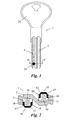
- reference numeral 1 generally designates a non-copyable flat security key according to an exemplary embodiment of the present invention.
- the key comprises a head 22 and a shank 2 with a flattened profile, adapted to be inserted in a slot 3 (see Figure 3 ) existing in a cylindrical rotor 4 which can rotate about a rotation axis in a cylindrical stator 5 of a security cylinder 20.
- the shank 2 has a paracentric profile and defines two opposite flat faces, in which longitudinal channels are formed.
- a plurality of mutually aligned recesses 6 are formed along both faces of the shank 2, which recesses are prepared to engage first detecting pins 7 (see Figure 4 ) housed in cylindrical holes formed in the mentioned rotor 4.
- first detecting pins 7 In a predetermined angular position of the rotor 4 with respect the stator 5, these first detecting pins 7 are in contact with respective locking pins 8 housed in cylindrical holes formed in said stator 5, and the first locking pins 8 are pushed towards said slot 3 by first springs 9. Plugs 21 retain the pins 7, 8 and springs 9 in their cylindrical holes. When the key is not introduced in the slot 3 of the cylinder 20, the first springs 9 move the detecting and locking pins 7, 8 inwards such that the locking pins 9 are traversed between the rotor 4 and the stator 5, thus preventing the rotation of the rotor 4.
- the recesses 6 of the key 1 can have different depths and the detecting and locking pins 7, 8 corresponding to each recess 6 are sized to be moved by the key 1 such that the surfaces in contact between each pair of detecting and locking pins 7, 8 coincide with the surfaces in contact between the rotor 4 and the stator 5.
- the shank 2 of the key 1 includes, in each face thereof, a moving element 10 retained in a housing 11, which moving element 10 can move between an extended position (shown in Figure 2 ), in which a conical or frustoconical end 12 of said moving element 10 projects from the shank 2, and a retracted position, in which the moving element 10 does not project from the shank 2.
- a third spring 16 is arranged in said housing 11 to push the moving element 10 towards its extended position.
- the housing 11 is located at each face of the shank 2 aligned with the plurality of recesses 6 ( Figure 1 ) and the moving element 10 is arranged to move in the housing 11 perpendicular to the respective face of the shank 2.
- the mentioned conical or frustoconical end 12 of the moving element 10 is adapted to engage a second detecting pin 13 housed in a cylindrical hole formed in the rotor 4, in contact, when the rotor 4 is in a predetermined angular position with respect the stator 5, with a corresponding second locking pin 14 housed in a corresponding cylindrical hole formed in the stator 5 and pushed towards the slot 3 by a second spring 15.
- the mentioned second detecting and locking pins 13, 14 are arranged in parallel and aligned with said first detecting and locking pins 7, 8 in the rotor 4 and in the stator 5, respectively, which is a constructive advantage compared to other cylinders of the prior art.
- the mentioned third spring 16 is selected such that the pushing force exerted by the moving element 10 against the second detecting pin 13 when the key 1 is introduced in the slot 3 of the cylinder 20 can move said second detecting and locking pins 13, 14 against the pushing force of the second spring 15 in order to locate the surfaces in contact between the second detecting and locking pins 13, 14 in coincidence with the surfaces in contact between the rotor 4 and the stator 5, and thus allow the rotation of the rotor 4.
- the slot 3 is located in the stator 4 so as it is substantially aligned with the rotation axis of the rotor 4, and the first and second detecting pins 7, 13 are arranged parallel to each other, perpendicular to the slot 3, and all together in a same plane at one side of the slot 3 in the rotor 4.
- the first and second locking pins 8, 14 are arranged parallel to each other, perpendicular to the rotation axis of the rotor 4, and all together in a same plane at one side of the rotor 4 in the stator 5.
- the first and second detecting pins 7, 13 in the rotor 4 are aligned with the corresponding first and second locking pins 8, 14 in the stator 5 allowing for the axial movement of the first and second detecting and locking pins 7, 8, 13, 14 upon introduction of the shank 2 of the key into the slot 3.
- Such an arrangement provides the security cylinder of the invention with a very compact configuration compared to other cylinders of the previous art having comparable performances.
- Each housing 11 formed in the shank 2 of the key 1 is a blind hole provided with a bottom (see Figure 2 ).
- the moving element 10 is partially hollow and defines a cavity 17 facing said bottom of the blind hole forming the housing 11.
- the mentioned third spring 16 is in the form of a helical spring and is partially housed in said cavity 17 of the moving element 10 and arranged under compression between the bottom of the housing 11 and the moving element 10.
- the housing 11 has an inner cylindrical surface and the moving element 10 comprises an outer cylindrical surface portion with an outer diameter that is smaller than the inner diameter of the housing 11.
- An annular flange 18 with an outer diameter that is substantially equal to the inner diameter of the housing 11 is formed at an end of said outer cylindrical surface of the moving element 10 closest to the bottom of the housing 11.
- a retaining ring 19 is joined to said inner cylindrical surface of the housing 11 next to the opening thereof to abut against said annular flange 18 of the moving element 10 when the latter is in the extended position thereof.
- This retaining ring 19 ensures that the moving element 10 cannot come out if the housing 11 while the retaining ring is completely introduced in the housing 11 without projecting from the corresponding face of the shank 2 of the key, the retaining ring 19 is therefore virtually immune to wearing.
- the housing 11 with the moving element 10 is located in an end of the shank 2 farthest from the head 22 of the key 1, at the end of the row of recesses 6.
- the housing 11 with the moving element 10 can be located in any other position, either at the end of the row of recesses 6 in the other end of the shank 2 closest to the head 22, or in an intermediate area of the shank 2 between two of the recesses 6.
Applications Claiming Priority (1)
| Application Number | Priority Date | Filing Date | Title |
|---|---|---|---|
| ES200602430U ES1064119Y (es) | 2006-11-13 | 2006-11-13 | Llave plana de seguridad, incopiable |
Publications (2)
| Publication Number | Publication Date |
|---|---|
| EP1921232A2 true EP1921232A2 (de) | 2008-05-14 |
| EP1921232A3 EP1921232A3 (de) | 2010-11-24 |
Family
ID=38290948
Family Applications (1)
| Application Number | Title | Priority Date | Filing Date |
|---|---|---|---|
| EP07380275A Withdrawn EP1921232A3 (de) | 2006-11-13 | 2007-10-15 | Nicht kopierbarer flacher Sicherheitsschlüssel und Sicherheitszylinder |
Country Status (2)
| Country | Link |
|---|---|
| EP (1) | EP1921232A3 (de) |
| ES (1) | ES1064119Y (de) |
Cited By (3)
| Publication number | Priority date | Publication date | Assignee | Title |
|---|---|---|---|---|
| DE102011014797B3 (de) * | 2011-02-25 | 2012-03-01 | Assa Abloy Sicherheitstechnik Gmbh | Schließzylinder mit zugehörigem Schlüssel |
| CN103615155A (zh) * | 2013-05-15 | 2014-03-05 | 林宏韬 | 防盗锁芯 |
| CN111350418A (zh) * | 2020-03-07 | 2020-06-30 | 张云鹏 | 一种安防门锁 |
Families Citing this family (1)
| Publication number | Priority date | Publication date | Assignee | Title |
|---|---|---|---|---|
| ES2331394B1 (es) * | 2007-08-06 | 2010-06-07 | Talleres De Escoriaza, S.A. | "llave de cerradura con insertos estaticos". |
Citations (4)
| Publication number | Priority date | Publication date | Assignee | Title |
|---|---|---|---|---|
| ES8503771A1 (es) * | 1984-05-18 | 1985-04-01 | Talleres Escoriaza Sa | Sistema de llave para cerraduras |
| WO2000022263A1 (en) * | 1998-10-15 | 2000-04-20 | Cisa S.P.A. | Cylinder lock with effraction-resistant device |
| WO2000053870A1 (en) * | 1999-03-08 | 2000-09-14 | Ziv Av Amir | Cylinder lock with rotatable pins |
| WO2000057006A1 (en) * | 1999-03-22 | 2000-09-28 | Hamafteah Hamistovev Ltd | Key blank with resiliently protruding pins |
-
2006
- 2006-11-13 ES ES200602430U patent/ES1064119Y/es not_active Expired - Fee Related
-
2007
- 2007-10-15 EP EP07380275A patent/EP1921232A3/de not_active Withdrawn
Patent Citations (4)
| Publication number | Priority date | Publication date | Assignee | Title |
|---|---|---|---|---|
| ES8503771A1 (es) * | 1984-05-18 | 1985-04-01 | Talleres Escoriaza Sa | Sistema de llave para cerraduras |
| WO2000022263A1 (en) * | 1998-10-15 | 2000-04-20 | Cisa S.P.A. | Cylinder lock with effraction-resistant device |
| WO2000053870A1 (en) * | 1999-03-08 | 2000-09-14 | Ziv Av Amir | Cylinder lock with rotatable pins |
| WO2000057006A1 (en) * | 1999-03-22 | 2000-09-28 | Hamafteah Hamistovev Ltd | Key blank with resiliently protruding pins |
Cited By (5)
| Publication number | Priority date | Publication date | Assignee | Title |
|---|---|---|---|---|
| DE102011014797B3 (de) * | 2011-02-25 | 2012-03-01 | Assa Abloy Sicherheitstechnik Gmbh | Schließzylinder mit zugehörigem Schlüssel |
| CN103615155A (zh) * | 2013-05-15 | 2014-03-05 | 林宏韬 | 防盗锁芯 |
| WO2014183409A1 (zh) * | 2013-05-15 | 2014-11-20 | Lin Hongtao | 防盗锁芯 |
| CN111350418A (zh) * | 2020-03-07 | 2020-06-30 | 张云鹏 | 一种安防门锁 |
| CN111350418B (zh) * | 2020-03-07 | 2021-10-12 | 渭南市金盾护卫有限公司 | 一种安防门锁 |
Also Published As
| Publication number | Publication date |
|---|---|
| EP1921232A3 (de) | 2010-11-24 |
| ES1064119Y (es) | 2007-05-01 |
| ES1064119U (es) | 2007-02-01 |
Similar Documents
| Publication | Publication Date | Title |
|---|---|---|
| EP2307640B1 (de) | Schlüsselrohling, herstellungsverfahren für schlüsselrohling | |
| US4008588A (en) | Rotary plug cylinder lock construction | |
| EP0605932B1 (de) | Verriegelungsvorrichtung | |
| US4478061A (en) | Cylinder lock | |
| US3935720A (en) | Rotatable cylinder lock | |
| US6758074B1 (en) | High-security round key and lock therefor | |
| EP2992152B1 (de) | Zylinderschloss mit antibruchfunktion | |
| US4083212A (en) | Rotary disc tumbler cylinder lock | |
| US8336346B2 (en) | High security moving mass lock system | |
| KR102408684B1 (ko) | 자물쇠용 열쇠 및 실린더 자물쇠와 평판형 반전가능 열쇠의 조합 | |
| US8635022B2 (en) | Cylinder lock | |
| US9140034B2 (en) | Lock assembly with movable element | |
| US20150247344A1 (en) | Lock cylinder including modular plug | |
| EP1921232A2 (de) | Nicht kopierbarer flacher Sicherheitsschlüssel und Sicherheitszylinder | |
| US8485006B2 (en) | Disc tumbler cylinder lock and key combination | |
| EP2984261B1 (de) | Zylinderschloss | |
| US6481254B1 (en) | Cylinder lock combined with a magnetic pin and a non-magnetic pin | |
| US10125521B2 (en) | Magnetic lock system | |
| US20160376815A1 (en) | High-security cylinder lock based on bridge tumblers | |
| JP7278265B2 (ja) | ロック装置 | |
| NZ529337A (en) | Lock cylinder | |
| US20100024499A1 (en) | High Security Cylinder Lock | |
| EP0065813A2 (de) | Zylinderschloss | |
| WO2010015909A2 (en) | High security cylinder lock | |
| EP2990568B1 (de) | Codierungsschliesszylinder in einem zylinderschlosskern und zylinderschlosskern mit codierungsschliesszylinder |
Legal Events
| Date | Code | Title | Description |
|---|---|---|---|
| PUAI | Public reference made under article 153(3) epc to a published international application that has entered the european phase |
Free format text: ORIGINAL CODE: 0009012 |
|
| AK | Designated contracting states |
Kind code of ref document: A2 Designated state(s): AT BE BG CH CY CZ DE DK EE ES FI FR GB GR HU IE IS IT LI LT LU LV MC MT NL PL PT RO SE SI SK TR |
|
| AX | Request for extension of the european patent |
Extension state: AL BA HR MK RS |
|
| PUAL | Search report despatched |
Free format text: ORIGINAL CODE: 0009013 |
|
| AK | Designated contracting states |
Kind code of ref document: A3 Designated state(s): AT BE BG CH CY CZ DE DK EE ES FI FR GB GR HU IE IS IT LI LT LU LV MC MT NL PL PT RO SE SI SK TR |
|
| AX | Request for extension of the european patent |
Extension state: AL BA HR MK RS |
|
| REG | Reference to a national code |
Ref country code: DE Ref legal event code: R108 |
|
| AKY | No designation fees paid | ||
| REG | Reference to a national code |
Ref country code: DE Ref legal event code: R108 Effective date: 20110720 |
|
| STAA | Information on the status of an ep patent application or granted ep patent |
Free format text: STATUS: THE APPLICATION IS DEEMED TO BE WITHDRAWN |
|
| 18D | Application deemed to be withdrawn |
Effective date: 20110502 |