EP1920908B1 - Procédé destiné déposer de grandes bandes de textile - Google Patents
Procédé destiné déposer de grandes bandes de textile Download PDFInfo
- Publication number
- EP1920908B1 EP1920908B1 EP07021377.2A EP07021377A EP1920908B1 EP 1920908 B1 EP1920908 B1 EP 1920908B1 EP 07021377 A EP07021377 A EP 07021377A EP 1920908 B1 EP1920908 B1 EP 1920908B1
- Authority
- EP
- European Patent Office
- Prior art keywords
- textile fibre
- fibre sheet
- stacking
- roll
- textile fiber
- Prior art date
- Legal status (The legal status is an assumption and is not a legal conclusion. Google has not performed a legal analysis and makes no representation as to the accuracy of the status listed.)
- Active
Links
- 239000000835 fiber Substances 0.000 title claims description 95
- 239000004753 textile Substances 0.000 title claims description 82
- 238000000034 method Methods 0.000 title claims description 29
- 239000004744 fabric Substances 0.000 claims description 16
- 230000003287 optical effect Effects 0.000 claims description 7
- 238000012544 monitoring process Methods 0.000 claims description 4
- 229920002430 Fibre-reinforced plastic Polymers 0.000 claims description 3
- 239000011151 fibre-reinforced plastic Substances 0.000 claims description 3
- 238000004519 manufacturing process Methods 0.000 claims description 3
- 230000004888 barrier function Effects 0.000 claims description 2
- 239000011230 binding agent Substances 0.000 claims description 2
- 238000003825 pressing Methods 0.000 claims description 2
- 238000000151 deposition Methods 0.000 description 11
- 238000003860 storage Methods 0.000 description 5
- 238000005520 cutting process Methods 0.000 description 4
- 239000002657 fibrous material Substances 0.000 description 4
- 210000001170 unmyelinated nerve fiber Anatomy 0.000 description 3
- 230000006978 adaptation Effects 0.000 description 2
- 239000004918 carbon fiber reinforced polymer Substances 0.000 description 2
- 238000005056 compaction Methods 0.000 description 2
- 230000001419 dependent effect Effects 0.000 description 2
- 239000000463 material Substances 0.000 description 2
- 239000011347 resin Substances 0.000 description 2
- 229920005989 resin Polymers 0.000 description 2
- 102100040287 GTP cyclohydrolase 1 feedback regulatory protein Human genes 0.000 description 1
- 101710185324 GTP cyclohydrolase 1 feedback regulatory protein Proteins 0.000 description 1
- 230000001070 adhesive effect Effects 0.000 description 1
- 239000004760 aramid Substances 0.000 description 1
- 229920006231 aramid fiber Polymers 0.000 description 1
- 239000003795 chemical substances by application Substances 0.000 description 1
- 239000002131 composite material Substances 0.000 description 1
- 238000010276 construction Methods 0.000 description 1
- 230000008021 deposition Effects 0.000 description 1
- 239000003365 glass fiber Substances 0.000 description 1
- 238000005470 impregnation Methods 0.000 description 1
- 239000000155 melt Substances 0.000 description 1
- 230000001105 regulatory effect Effects 0.000 description 1
- 229920001169 thermoplastic Polymers 0.000 description 1
- 239000004416 thermosoftening plastic Substances 0.000 description 1
- 239000002759 woven fabric Substances 0.000 description 1
Images


Classifications
-
- B—PERFORMING OPERATIONS; TRANSPORTING
- B29—WORKING OF PLASTICS; WORKING OF SUBSTANCES IN A PLASTIC STATE IN GENERAL
- B29C—SHAPING OR JOINING OF PLASTICS; SHAPING OF MATERIAL IN A PLASTIC STATE, NOT OTHERWISE PROVIDED FOR; AFTER-TREATMENT OF THE SHAPED PRODUCTS, e.g. REPAIRING
- B29C70/00—Shaping composites, i.e. plastics material comprising reinforcements, fillers or preformed parts, e.g. inserts
- B29C70/04—Shaping composites, i.e. plastics material comprising reinforcements, fillers or preformed parts, e.g. inserts comprising reinforcements only, e.g. self-reinforcing plastics
- B29C70/28—Shaping operations therefor
- B29C70/30—Shaping by lay-up, i.e. applying fibres, tape or broadsheet on a mould, former or core; Shaping by spray-up, i.e. spraying of fibres on a mould, former or core
- B29C70/38—Automated lay-up, e.g. using robots, laying filaments according to predetermined patterns
- B29C70/386—Automated tape laying [ATL]
-
- B—PERFORMING OPERATIONS; TRANSPORTING
- B29—WORKING OF PLASTICS; WORKING OF SUBSTANCES IN A PLASTIC STATE IN GENERAL
- B29C—SHAPING OR JOINING OF PLASTICS; SHAPING OF MATERIAL IN A PLASTIC STATE, NOT OTHERWISE PROVIDED FOR; AFTER-TREATMENT OF THE SHAPED PRODUCTS, e.g. REPAIRING
- B29C70/00—Shaping composites, i.e. plastics material comprising reinforcements, fillers or preformed parts, e.g. inserts
- B29C70/04—Shaping composites, i.e. plastics material comprising reinforcements, fillers or preformed parts, e.g. inserts comprising reinforcements only, e.g. self-reinforcing plastics
- B29C70/28—Shaping operations therefor
- B29C70/54—Component parts, details or accessories; Auxiliary operations, e.g. feeding or storage of prepregs or SMC after impregnation or during ageing
- B29C70/541—Positioning reinforcements in a mould, e.g. using clamping means for the reinforcement
-
- B—PERFORMING OPERATIONS; TRANSPORTING
- B29—WORKING OF PLASTICS; WORKING OF SUBSTANCES IN A PLASTIC STATE IN GENERAL
- B29C—SHAPING OR JOINING OF PLASTICS; SHAPING OF MATERIAL IN A PLASTIC STATE, NOT OTHERWISE PROVIDED FOR; AFTER-TREATMENT OF THE SHAPED PRODUCTS, e.g. REPAIRING
- B29C70/00—Shaping composites, i.e. plastics material comprising reinforcements, fillers or preformed parts, e.g. inserts
- B29C70/04—Shaping composites, i.e. plastics material comprising reinforcements, fillers or preformed parts, e.g. inserts comprising reinforcements only, e.g. self-reinforcing plastics
- B29C70/28—Shaping operations therefor
- B29C70/54—Component parts, details or accessories; Auxiliary operations, e.g. feeding or storage of prepregs or SMC after impregnation or during ageing
- B29C70/543—Fixing the position or configuration of fibrous reinforcements before or during moulding
-
- B—PERFORMING OPERATIONS; TRANSPORTING
- B29—WORKING OF PLASTICS; WORKING OF SUBSTANCES IN A PLASTIC STATE IN GENERAL
- B29C—SHAPING OR JOINING OF PLASTICS; SHAPING OF MATERIAL IN A PLASTIC STATE, NOT OTHERWISE PROVIDED FOR; AFTER-TREATMENT OF THE SHAPED PRODUCTS, e.g. REPAIRING
- B29C70/00—Shaping composites, i.e. plastics material comprising reinforcements, fillers or preformed parts, e.g. inserts
- B29C70/04—Shaping composites, i.e. plastics material comprising reinforcements, fillers or preformed parts, e.g. inserts comprising reinforcements only, e.g. self-reinforcing plastics
- B29C70/28—Shaping operations therefor
- B29C70/54—Component parts, details or accessories; Auxiliary operations, e.g. feeding or storage of prepregs or SMC after impregnation or during ageing
- B29C70/545—Perforating, cutting or machining during or after moulding
-
- B—PERFORMING OPERATIONS; TRANSPORTING
- B29—WORKING OF PLASTICS; WORKING OF SUBSTANCES IN A PLASTIC STATE IN GENERAL
- B29C—SHAPING OR JOINING OF PLASTICS; SHAPING OF MATERIAL IN A PLASTIC STATE, NOT OTHERWISE PROVIDED FOR; AFTER-TREATMENT OF THE SHAPED PRODUCTS, e.g. REPAIRING
- B29C70/00—Shaping composites, i.e. plastics material comprising reinforcements, fillers or preformed parts, e.g. inserts
- B29C70/04—Shaping composites, i.e. plastics material comprising reinforcements, fillers or preformed parts, e.g. inserts comprising reinforcements only, e.g. self-reinforcing plastics
- B29C70/28—Shaping operations therefor
- B29C70/54—Component parts, details or accessories; Auxiliary operations, e.g. feeding or storage of prepregs or SMC after impregnation or during ageing
- B29C70/56—Tensioning reinforcements before or during shaping
Definitions
- the invention relates to a method for depositing large textile fiber webs, in particular from C fibers, for the production of fiber-reinforced plastic components (for example CFRP, GFRP etc.). Under such a large textile fiber web are understood to be those with a width of at least 500 mm.
- fiber-reinforced plastic components for example CFRP, GFRP etc.
- the DE 697 17 053 T2 describes a tape laying head for the production of composite panels by storing textile fiber ribbons.
- the end of the to be deposited, resin pre-impregnated textile fiber tape is placed on a component mold.
- the tape laying head By moving the tape laying head, the textile fiber web is unrolled from the roll and deposited on the component mold.
- By means of a roller takes place simultaneously with the tray draping the textile fiber web.
- the EP 1 334 819 A1 describes a method for depositing pre-impregnated fiber ribbons, wherein the orientation of the deposited tapes by means of a camera continuously is monitored. Furthermore, means are provided with which the filing process is continuously monitored with regard to a predetermined storage rate.
- the EP 0 680 818 A2 and EP 0 846 551 describe a device for depositing pre-impregnated, very thin slivers. For the purpose of filing the sliver and to its compaction are in the EP 0 680 818 movably mounted rollers available.
- the textile fiber webs to be deposited are in the form of dry materials, i. they are not pre-impregnated with resin. Their adhesive property is obtained e.g. by a surface applied, e.g. thermoplastic binder fleece, which melts by heat.
- Dry textile fiber webs have the advantage that the individual fibers are determined differently than in the case of preimpregnated materials, but rather remain mobile within the fiber structure.
- Drapiervorgang the textile fiber webs thus very well adapted to a curved component surface.
- the draping process involves not only a compaction of the fiber material. Rather, a change in the fiber angle occurs within the fiber structure. The course of the fibers with each other changes. Due to this flexibility of the dry Fiber material is a storage of large textile fiber webs with a width of at least 500mm possible.
- draping agents are used, which are characterized by great flexibility and flexibility. These are sliding plates or movably mounted rollers.
- the textile fiber webs to be deposited have, in preferred embodiments, an area of at least 3 m 2 .
- a textile fiber web may in particular be present as a scrim (several rovings laid on one another and fixed, for example sewn) or as a woven fabric (individual fibers interwoven with one another).
- the textile fiber webs generally have parallel edges, but the webs may also be contoured in any manner (e.g., having at least partially curved edges).
- Fig. 1 to 3 show the three principal steps of the method according to the invention, in this case using the example of a substantially planar component surface.
- the method according to the invention is also and in particular suitable for depositing on arbitrarily curved surfaces.
- Fig. 1 First, the gripping of the dry textile fiber web 10 to be deposited is shown by means of cloth gripper 5.
- the textile fiber web 10 is rolled up in roll form (roll 1) on a driven roll axis.
- the roll axis is disposed on a towel dispenser 11 carried by a robot 60.
- the cloth gripper 5 carried by a second robot 50 is moved in position.
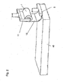
- the towel dispenser 11 positions the edge of the textile fiber web 10 over a receiving slot 7 (FIG. Fig. 9 ) of the cloth gripper 5, then the textile fiber web 10 is unrolled a defined length from the roll 1.
- the cloth gripper 5 is now raised, so that the edge of the textile fiber web 10 enters the receiving slot 7 of the cloth gripper 5.
- the textile fiber web 10 by inflating a tube 6 ( Fig. 9 ) fixed in the cloth gripper.
- the cloth gripper 5 is in Fig. 9 shown in more detail in two different operating phases. Adjacent thereto is a connected to a vacuum pump elastic hose 6 is arranged, which is vented in the Fig. A) and is inflated in the Fig. B). By inflating the tube 6, the tube is expanded, so that the textile fiber web 10 located in the receiving slot 7 is fixed.
- Fig. 2 describes the placement of the textile fiber web 10 on a component mold, wherein the mold, which is located on the storage table 40, is not shown for reasons of clarity.
- the component form may have a flat surface. However, arbitrarily curved shapes (eg cylindrical, spherical, etc) are possible.
- the textile fiber web 10 is unrolled to a certain length from the roll 1.
- the cloth gripper 5 places the textile fiber web 10 in a defined position and aligns the edges of the textile fiber web relative to the component shape accordingly. Before the cloth gripper 5 releases the textile fiber web again, becomes a short section filed off. After releasing the textile fiber web the cloth gripper 5 moves back to the basic position.
- the actual laying down of the textile fiber web 10 takes place by means of a linear movement of either the towel dispenser 11 or the depositing table 40.
- the textile fiber web 10 is deposited along a predetermined path.
- the path along which the textile fiber web 10 is to be deposited can be predetermined, for example, by means of an optical web edge control. This shows Fig. 4 ,
- the desired position predetermined according to the component structure is marked by one or more laser lines 12 projected onto the mold.
- Tuchabroller 11 is a sensor 13, for example, a so-called PSD chip, which is coupled to the control of the robot 60. This chip 13 compares the position of the projected laser line with a desired position. The robot controller accordingly corrects the position of the towel dispenser 11 until the two positions coincide.
- the Fig. 1 to 4 show the filing of a single textile fiber web in 0 ° direction. After cutting the textile fiber web further textile fiber webs can be stored on the same procedure on each other, with other deposit directions are possible, especially in the direction of 90 ° and ⁇ 45 °.
- the textile fiber web 10 When depositing it must be ensured that the textile fiber web 10 can be stored evenly, ie with a constant rate of deposition (deposited textile fiber surface per unit time). Both stresses in the fiber material and undulations in the deposited textile fiber web are to be avoided. For this purpose, the linear movement of the table 40 or Tuchabrollers 11 and the rotational movement of the roller 1 must be coordinated. Continuous regulation is necessary in particular since the diameter of the textile fiber web continuously changes as a result of unrolling the textile fiber web.
- One way to ensure a uniform shelf is to continuously determine the diameter of the roll 1.
- the diameter of the roller 1 is determined contactless by means of optical sensor 15 without contact.
- the necessary for a uniform storage speed of the motor that drives the roller 1 can be calculated.
- the dancer roll is a pivotable deflection roller, over which the textile fiber web 10 runs during the laying process 10.
- the deflection of the dancer roller 17 about the axis 19 on the towel dispenser 11 is dependent on the tension in the textile fiber web 10.
- a potentiometer With a potentiometer, the deflection can be converted into an electrical voltage.
- the speed of the motor for driving the roller 1 is regulated in dependence on the deflection of the dancer roller 17.
- a specific base speed is specified.
- Another possibility not shown in the figures for the automatic setting of a uniform filing can be achieved by the use of a light barrier. This determines the relative position of that portion of the textile fiber web which is currently between the roll and the delivery table to a nominal value via a brightness difference. A control circuit regulates the speed of the motor accordingly.
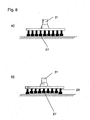
- a draping and fixing of the applied textile fiber web is carried out simultaneously with the depositing. This is in the Fig. 7 and 8th in two different versions ( Fig. 8 in a highly schematic representation).
- Fig. 7 are on Tuchabroller 11 more planar sliding elements 21, such as sliding plates attached, move during the movement of Tuchabrollers 11 during the filing process over the just laid textile fiber material.
- the Sliding elements 21 are heated.
- a binding fleece is applied, which is stored together with the textile fiber web 10.
- the binding fleece bonds the individual textile fiber webs laid one above the other to one another.
- the width of a sliding plate can be varied depending on the complexity of the surface shape of the component.
- Fig. A shows the use of the rollers 27 at a substantially planar component contour.
- Fig. B shows the use with a curved component contour.
- the rollers it is necessary for the rollers to be flexibly supported, for example by means of spring elements 29.
- Reference numeral 31 designates the mechanical connection to the towel dispenser 11. In order to adapt to the curved component surface, a change in the fiber angle occurs due to the draping process within the fiber structure.
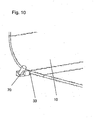
- the cutting of the textile fiber web 10 takes place along the component contour at the end of the deposited web, as in FIG Fig. 10 shown.
- a powered cutter 33 can be used.
- the cutting direction is preferably parallel to the axis of the roll 1.
- the cutter 33 is carried by a separate robot 70. Alternatively, it may also be arranged on the cloth roller 11.
Landscapes
- Engineering & Computer Science (AREA)
- Chemical & Material Sciences (AREA)
- Composite Materials (AREA)
- Mechanical Engineering (AREA)
- Textile Engineering (AREA)
- Robotics (AREA)
- Treatment Of Fiber Materials (AREA)
- Moulding By Coating Moulds (AREA)
Claims (8)
- Procédé destiné à déposer des bandes de fibres textiles (10) sur un moule de composant pour la fabrication de composants en plastique renforcés par des fibres, la bande de fibres textiles (10) se présentant sous la forme d'un rouleau (1), la dépose étant effectuée complètement automatiquement au moyen de robots (50, 60), et- l'extrémité de la bande de fibres textiles (10) à déposer étant saisie au moyen d'un dispositif de préhension de toile (5) portés par un robot et étant placée sur le moule de composant,- la bande de fibres textiles (10) étant déroulée du rouleau (1) au moyen d'un dispositif de déroulement de toile (11) portés par un robot et étant déposée sur le moule de composant,- pendant la dépose, un drapage de la bande de fibres textiles (10) au moyen d'une pluralité de tôles de glissement chauffées (21), supportées de manière flexible, portées par un robot, ou de rouleaux chauffés (27) supportés de manière déplaçable et portés par un robot étant effectué de telle sorte que par pression sur la bande de fibres textiles (10), la bande de fibres textiles (10) soit adaptée à une surface courbe du moule de composant,- l'opération de dépose étant contrôlée en continu en termes de vitesse de dépose constante et la vitesse de dépose étant corrigée automatiquement le cas échéant,- l'orientation de la bande de fibres textiles (10) par rapport au moule de composant étant contrôlée en continu au moyen de moyens optiques (13) et étant corrigée le cas échéant,- les bandes de fibres textiles (10) se présentant sous la forme de grandes bandes de fibres textiles sèches (10) ayant une largeur d'au moins 500 mm qui présentent sur leur surface un non-tissé liant.
- Procédé selon la revendication 1, caractérisé en ce que le contrôle de l'opération de dépose en termes d'une vitesse de dépose constante est effectué de telle sorte que la bande de fibres textiles à déposer (10) soit contrôlée en continu en termes de traction.
- Procédé selon la revendication 2, caractérisé en ce que le contrôle de traction continu de la bande de fibres textiles (10) est effectué au moyen d'un rouleau danseur (17).
- Procédé selon la revendication 1, caractérisé en ce qu'une vitesse de dépose constante est garantie de telle sorte que le diamètre du rouleau (1) soit mesuré en continu.
- Procédé selon la revendication 1, caractérisé en ce que le contrôle de l'opération de dépose en termes d'une vitesse de dépose constante est effectué de telle sorte que la position de la portion de bande de fibres textiles (10) déroulée momentanément du rouleau (1) soit mesurée par rapport à une valeur de consigne au moyen d'une barrière lumineuse.
- Procédé selon l'une quelconque des revendications précédentes, caractérisé en ce que la bande de fibres textiles déposée (10), une fois la position finale de dépose atteinte, est séparée du rouleau (1) au moyen d'un dispositif de découpe (33) portés par un robot.
- Procédé selon l'une quelconque des revendications précédentes, caractérisé en ce que l'orientation continue de la bande de fibres textiles (10) est effectuée de telle sorte qu'un bord de bande de consigne optique (12) soit projeté sur le moule de composant, lequel est détecté par un capteur optique (13) du côté du rouleau.
- Procédé selon l'une quelconque des revendications précédentes, caractérisé en ce que la préhension de l'extrémité de la bande de fibres textiles à déposer (10) s'effectue au moyen d'un dispositif de préhension de toile (5), la fixation de la bande de fibres textiles (10) au dispositif de préhension de toile (5) s'effectuant par l'expansion d'un élément élastique gonflable (6).
Applications Claiming Priority (1)
| Application Number | Priority Date | Filing Date | Title |
|---|---|---|---|
| DE102006052592A DE102006052592B4 (de) | 2006-11-08 | 2006-11-08 | Verfahren zur Ablage großer trockener Textilfaserbahnen |
Publications (2)
| Publication Number | Publication Date |
|---|---|
| EP1920908A1 EP1920908A1 (fr) | 2008-05-14 |
| EP1920908B1 true EP1920908B1 (fr) | 2015-04-08 |
Family
ID=39118022
Family Applications (1)
| Application Number | Title | Priority Date | Filing Date |
|---|---|---|---|
| EP07021377.2A Active EP1920908B1 (fr) | 2006-11-08 | 2007-11-02 | Procédé destiné déposer de grandes bandes de textile |
Country Status (4)
| Country | Link |
|---|---|
| US (1) | US20080169579A1 (fr) |
| EP (1) | EP1920908B1 (fr) |
| DE (1) | DE102006052592B4 (fr) |
| ES (1) | ES2541775T3 (fr) |
Families Citing this family (25)
| Publication number | Priority date | Publication date | Assignee | Title |
|---|---|---|---|---|
| DE102008004261B3 (de) * | 2008-01-14 | 2009-04-16 | Universität Bremen | Verfahren und Vorrichtung zum Ablegen eines aufgerollten Materials |
| DE102008042574B4 (de) | 2008-10-02 | 2010-06-10 | Airbus Deutschland Gmbh | Vorrichtung zum Ablegen und Drapieren von Abschnitten einer Verstärkungsfaserstruktur zur Herstellung eines Profilvorformlings sowie Verfahren |
| DK2362825T3 (en) * | 2008-11-12 | 2017-07-10 | Lm Wp Patent Holding As | A METHOD OF LAYING A LAYER OF FIBER MATERIAL AND THE RELATED APPARATUS |
| WO2010129492A2 (fr) * | 2009-05-04 | 2010-11-11 | Lamb Assembly And Test, Llc | Application de disposition de matériau rapide pour fabrication de pale d'éolienne |
| FR2958575B1 (fr) * | 2010-04-13 | 2013-03-15 | Airbus Operations Sas | Procede et dispositif pour la fabrication automatisee de preformes seche. |
| GB201013885D0 (en) * | 2010-08-19 | 2010-10-06 | Univ Nottingham | An apparatus and method for the layup of sheets to form a composite article and composite articles made thereby |
| FR2981881B1 (fr) * | 2011-10-26 | 2013-12-13 | Snecma | Dispositif de maintien d'une texture fibreuse sur un mandrin d'impregnation d'une machine d'enroulement |
| US8826957B2 (en) | 2012-08-31 | 2014-09-09 | General Electric Company | Methods and systems for automated ply layup for composites |
| DE102012017594B4 (de) * | 2012-09-06 | 2016-03-03 | Premium Aerotec Gmbh | Ablegekopf und Ablegeverfahren zum automatisierten Ablegen von Zuschnitten eines flächigen Materials, insbesondere zur Herstellung von großflächigen Faserverbundbauteilen |
| DE102012017595B4 (de) * | 2012-09-06 | 2014-08-21 | Premium Aerotec Gmbh | Ablegekopf und Ablegeverfahren zum automatisierten Ablegen von Zuschnitten eines flächigen Materials, insbesondere zur Herstellung von großflächigen Faserverbundbauteilen |
| DE102012017593B4 (de) * | 2012-09-06 | 2016-04-28 | Premium Aerotec Gmbh | Ablegekopf und Ablegeverfahren zum automatisierten Ablegen von Zuschnitten eines flächigen Materials, insbesondere zur Herstellung von großflächigen Faserverbundbauteilen |
| US10875287B2 (en) | 2012-09-18 | 2020-12-29 | Vestas Wind Systems A/S | Wind turbine blades |
| DE102012219267A1 (de) * | 2012-10-22 | 2014-04-24 | Wobben Properties Gmbh | Verfahren und Vorrichtung zur Herstellung von Vorformlingen zum Herstellen eines Rotorblattes |
| EP2953784B1 (fr) * | 2013-02-08 | 2020-07-29 | LM WP Patent Holding A/S | Système et procédé pour la fabrication d'un article en fibre composite |
| FR3033280B1 (fr) * | 2015-03-06 | 2017-03-10 | Coriolis Composites | Procede d'inspection de fibres drapees par une machine de placement de fibres |
| AT517186B1 (de) * | 2015-05-12 | 2017-03-15 | Fill Gmbh | Greifer mit zumindest einem Klemmelement |
| DE102015108943B4 (de) | 2015-06-08 | 2019-02-28 | Universität Bremen | Drapiermodul zum Drapieren von textilen Bahnen auf einem Formwerkzeug, Vorrichtung mit demselben sowie Verfahren zum automatisierten Ablegen und Drapieren von textilen Bahnen |
| FR3052100B1 (fr) * | 2016-06-02 | 2019-03-15 | Airbus Operations | Dispositif de depose automatique de plis de fibres de grandes dimensions |
| WO2018037016A1 (fr) * | 2016-08-26 | 2018-03-01 | Basf Se | Mousse renforcée de fibres |
| DE102016120604A1 (de) * | 2016-10-27 | 2018-05-03 | Dieffenbacher GmbH Maschinen- und Anlagenbau | Verfahren und Tapelegevorrichtung zum Aufbau eines Laminats im Zuge der Herstellung von Vorformlingen |
| US11478997B2 (en) * | 2019-09-12 | 2022-10-25 | The Boeing Company | Automated fiber placement system and associated method |
| US10987814B1 (en) * | 2020-06-01 | 2021-04-27 | Softwear Automation, Inc. | Compliant perimeter end effectors |
| CN112482007B (zh) * | 2020-11-06 | 2022-06-14 | 湖北工业大学 | 一种铺布与裁布一体化装置 |
| EP4241970A1 (fr) * | 2022-03-09 | 2023-09-13 | LM Wind Power A/S | Appareil et procédés de dépôt de tapis de fibres |
| CN118029124A (zh) * | 2024-04-15 | 2024-05-14 | 晋江晶日鞋材有限公司 | 一种纺织织针裁脚机 |
Family Cites Families (13)
| Publication number | Priority date | Publication date | Assignee | Title |
|---|---|---|---|---|
| JPH0725143B2 (ja) * | 1988-03-28 | 1995-03-22 | 新日本工機株式会社 | テープの自動貼付装置 |
| DE4212135C2 (de) * | 1992-04-10 | 1997-08-21 | Dornier Gmbh | Verfahren und Vorrichtung zur Herstellung von Gelegen |
| US5518231A (en) * | 1993-04-19 | 1996-05-21 | Xerox Corporation | Self adjusting sheet gripping apparatus |
| US5352306A (en) * | 1993-05-27 | 1994-10-04 | Cincinnati Milacron Inc. | Tape laying apparatus and method |
| US6045651A (en) * | 1993-09-07 | 2000-04-04 | The Boeing Company | Hand assisted lamination system |
| US5454897A (en) * | 1994-05-02 | 1995-10-03 | Cincinnati Milacron Inc. | Presser member for fiber laying machine |
| FR2756510B1 (fr) * | 1996-12-03 | 1999-02-12 | Aerospatiale | Tete de drapage, pour la fabrication de plaques en materiau composite |
| US6390169B1 (en) * | 2000-02-23 | 2002-05-21 | The Boeing Company | Conformable compaction apparatus for use with a fiber placement machine |
| US6799619B2 (en) * | 2002-02-06 | 2004-10-05 | The Boeing Company | Composite material collation machine and associated method for high rate collation of composite materials |
| US7341086B2 (en) * | 2004-10-29 | 2008-03-11 | The Boeing Company | Automated fabric layup system and method |
| US7536242B2 (en) * | 2004-11-12 | 2009-05-19 | The Boeing Company | Optical laser guidance system apparatus and method |
| US7455742B2 (en) | 2005-02-16 | 2008-11-25 | The Boeing Company | Slit-course ply placement device and method |
| US7601237B2 (en) * | 2006-02-01 | 2009-10-13 | The Boeing Company | Fabric handling apparatus and method for composite manufacture |
-
2006
- 2006-11-08 DE DE102006052592A patent/DE102006052592B4/de not_active Expired - Fee Related
-
2007
- 2007-11-02 EP EP07021377.2A patent/EP1920908B1/fr active Active
- 2007-11-02 ES ES07021377.2T patent/ES2541775T3/es active Active
- 2007-11-07 US US11/936,468 patent/US20080169579A1/en not_active Abandoned
Also Published As
| Publication number | Publication date |
|---|---|
| DE102006052592A1 (de) | 2008-05-15 |
| EP1920908A1 (fr) | 2008-05-14 |
| DE102006052592B4 (de) | 2013-09-12 |
| US20080169579A1 (en) | 2008-07-17 |
| ES2541775T3 (es) | 2015-07-24 |
Similar Documents
| Publication | Publication Date | Title |
|---|---|---|
| EP1920908B1 (fr) | Procédé destiné déposer de grandes bandes de textile | |
| EP3377308B1 (fr) | Installation de fabrication pour poser des bandes de fibres | |
| EP2754548B1 (fr) | Procédé de fabrication des préformes pour des matériaux composites renforcés par des fibres | |
| EP0243688B1 (fr) | Dispositif pour déposer un ruban de fibres préimprégné | |
| EP3386735B1 (fr) | Dispositif de dépôt pour des mèches de fibres | |
| EP2694262B1 (fr) | Dispositif et procédé de fabrication de préformes à fibres constituant notamment une phase préalable dans la fabrication de composants plastiques renforcés par fibres | |
| DE102006021110B4 (de) | Vorrichtung und Verfahren zum Herstellen eines großflächigen Faserverbund-Strukturbauteils | |
| EP2822754B1 (fr) | Application transversale de fibres | |
| DE102012017593B4 (de) | Ablegekopf und Ablegeverfahren zum automatisierten Ablegen von Zuschnitten eines flächigen Materials, insbesondere zur Herstellung von großflächigen Faserverbundbauteilen | |
| EP3678851B1 (fr) | Dispositif et procédé de fabrication pour la déposition des rubans de fibres | |
| EP2508327B1 (fr) | Procédé et dispositif destinés au traitement d'une bande | |
| DE102012017594B4 (de) | Ablegekopf und Ablegeverfahren zum automatisierten Ablegen von Zuschnitten eines flächigen Materials, insbesondere zur Herstellung von großflächigen Faserverbundbauteilen | |
| WO2012136391A1 (fr) | Dispositif et procédé de fabrication de préformes à fibres constituant notamment une phase préalable dans la fabrication de composants plastiques renforcés par fibres | |
| EP3294533B1 (fr) | Dispositif de préhension muni d'au moins un élément de serrage | |
| WO2014053305A1 (fr) | Procédé de fabrication de préformes fibreuses qui représentent en particulier une étape préalable lors de la fabrication d'éléments en plastique renforcés par des fibres | |
| DE102013200131B4 (de) | Automatisiertes Materialfördersystem, Materialeinbringungsanordnung und Verfahren zum Ausbilden einer Verbundstruktur | |
| DE202016001601U1 (de) | Vorrichtung zum Herstellen eines Rovingbands und/oder zum Herstellen eines faserverstärkten Verbundwerkstoffes | |
| WO2014012774A1 (fr) | Dispositif et procédé de fabrication de composants en matière plastique renforcée par des fibres |
Legal Events
| Date | Code | Title | Description |
|---|---|---|---|
| PUAI | Public reference made under article 153(3) epc to a published international application that has entered the european phase |
Free format text: ORIGINAL CODE: 0009012 |
|
| AK | Designated contracting states |
Kind code of ref document: A1 Designated state(s): AT BE BG CH CY CZ DE DK EE ES FI FR GB GR HU IE IS IT LI LT LU LV MC MT NL PL PT RO SE SI SK TR |
|
| AX | Request for extension of the european patent |
Extension state: AL BA HR MK RS |
|
| RIN1 | Information on inventor provided before grant (corrected) |
Inventor name: BERCHTHOLD, GERD, DR. Inventor name: STADLER, FRANZ Inventor name: MUELLER-HUMMEL, PETER, DR. Inventor name: TER, PATRICK Inventor name: SCHOLLER, JOCHEN |
|
| 17P | Request for examination filed |
Effective date: 20080913 |
|
| 17Q | First examination report despatched |
Effective date: 20081010 |
|
| AKX | Designation fees paid |
Designated state(s): DE ES FR GB IT |
|
| RAP1 | Party data changed (applicant data changed or rights of an application transferred) |
Owner name: AIRBUS DEFENCE AND SPACE GMBH |
|
| GRAP | Despatch of communication of intention to grant a patent |
Free format text: ORIGINAL CODE: EPIDOSNIGR1 |
|
| INTG | Intention to grant announced |
Effective date: 20141029 |
|
| RIN1 | Information on inventor provided before grant (corrected) |
Inventor name: SCHOLLER, JOCHEN Inventor name: BERCHTHOLD, GERD Inventor name: STADLER, FRANZ Inventor name: TER, PATRICK Inventor name: MUELLER-HUMMEL, PETER |
|
| GRAS | Grant fee paid |
Free format text: ORIGINAL CODE: EPIDOSNIGR3 |
|
| GRAA | (expected) grant |
Free format text: ORIGINAL CODE: 0009210 |
|
| AK | Designated contracting states |
Kind code of ref document: B1 Designated state(s): DE ES FR GB IT |
|
| REG | Reference to a national code |
Ref country code: GB Ref legal event code: FG4D Free format text: NOT ENGLISH |
|
| REG | Reference to a national code |
Ref country code: DE Ref legal event code: R096 Ref document number: 502007013849 Country of ref document: DE Effective date: 20150521 |
|
| REG | Reference to a national code |
Ref country code: ES Ref legal event code: FG2A Ref document number: 2541775 Country of ref document: ES Kind code of ref document: T3 Effective date: 20150724 |
|
| REG | Reference to a national code |
Ref country code: FR Ref legal event code: PLFP Year of fee payment: 9 |
|
| REG | Reference to a national code |
Ref country code: DE Ref legal event code: R097 Ref document number: 502007013849 Country of ref document: DE |
|
| PLBE | No opposition filed within time limit |
Free format text: ORIGINAL CODE: 0009261 |
|
| STAA | Information on the status of an ep patent application or granted ep patent |
Free format text: STATUS: NO OPPOSITION FILED WITHIN TIME LIMIT |
|
| 26N | No opposition filed |
Effective date: 20160111 |
|
| REG | Reference to a national code |
Ref country code: FR Ref legal event code: PLFP Year of fee payment: 10 |
|
| REG | Reference to a national code |
Ref country code: FR Ref legal event code: PLFP Year of fee payment: 11 |
|
| PGFP | Annual fee paid to national office [announced via postgrant information from national office to epo] |
Ref country code: GB Payment date: 20231123 Year of fee payment: 17 |
|
| PGFP | Annual fee paid to national office [announced via postgrant information from national office to epo] |
Ref country code: IT Payment date: 20231124 Year of fee payment: 17 Ref country code: FR Payment date: 20231120 Year of fee payment: 17 Ref country code: DE Payment date: 20231121 Year of fee payment: 17 |
|
| PGFP | Annual fee paid to national office [announced via postgrant information from national office to epo] |
Ref country code: ES Payment date: 20240124 Year of fee payment: 17 |