EP1920724A1 - Cutting radio frequency catheter for creating fenestrations in graft cloth - Google Patents
Cutting radio frequency catheter for creating fenestrations in graft cloth Download PDFInfo
- Publication number
- EP1920724A1 EP1920724A1 EP07021659A EP07021659A EP1920724A1 EP 1920724 A1 EP1920724 A1 EP 1920724A1 EP 07021659 A EP07021659 A EP 07021659A EP 07021659 A EP07021659 A EP 07021659A EP 1920724 A1 EP1920724 A1 EP 1920724A1
- Authority
- EP
- European Patent Office
- Prior art keywords
- electrode
- cutting
- graft material
- side opening
- catheter assembly
- Prior art date
- Legal status (The legal status is an assumption and is not a legal conclusion. Google has not performed a legal analysis and makes no representation as to the accuracy of the status listed.)
- Withdrawn
Links
- 238000005520 cutting process Methods 0.000 title claims abstract description 32
- 239000004744 fabric Substances 0.000 title description 3
- 239000000463 material Substances 0.000 claims abstract description 97
- 238000011065 in-situ storage Methods 0.000 claims abstract description 7
- 239000004020 conductor Substances 0.000 claims description 42
- 238000000034 method Methods 0.000 claims description 31
- 239000012530 fluid Substances 0.000 claims description 6
- 239000003989 dielectric material Substances 0.000 claims description 5
- 239000003550 marker Substances 0.000 claims description 4
- 230000006378 damage Effects 0.000 description 8
- 206010002329 Aneurysm Diseases 0.000 description 7
- 210000003813 thumb Anatomy 0.000 description 5
- 230000015572 biosynthetic process Effects 0.000 description 4
- 239000000835 fiber Substances 0.000 description 4
- 238000004519 manufacturing process Methods 0.000 description 4
- 230000008878 coupling Effects 0.000 description 3
- 238000010168 coupling process Methods 0.000 description 3
- 238000005859 coupling reaction Methods 0.000 description 3
- HLXZNVUGXRDIFK-UHFFFAOYSA-N nickel titanium Chemical compound [Ti].[Ti].[Ti].[Ti].[Ti].[Ti].[Ti].[Ti].[Ti].[Ti].[Ti].[Ni].[Ni].[Ni].[Ni].[Ni].[Ni].[Ni].[Ni].[Ni].[Ni].[Ni].[Ni].[Ni].[Ni] HLXZNVUGXRDIFK-UHFFFAOYSA-N 0.000 description 3
- 229910001000 nickel titanium Inorganic materials 0.000 description 3
- 230000002787 reinforcement Effects 0.000 description 3
- 210000002254 renal artery Anatomy 0.000 description 3
- 210000000709 aorta Anatomy 0.000 description 2
- 230000000712 assembly Effects 0.000 description 2
- 238000000429 assembly Methods 0.000 description 2
- 239000008280 blood Substances 0.000 description 2
- 210000004369 blood Anatomy 0.000 description 2
- 239000011248 coating agent Substances 0.000 description 2
- 238000000576 coating method Methods 0.000 description 2
- -1 e.g. Substances 0.000 description 2
- 230000005284 excitation Effects 0.000 description 2
- 238000003384 imaging method Methods 0.000 description 2
- 210000001363 mesenteric artery superior Anatomy 0.000 description 2
- 229910052751 metal Inorganic materials 0.000 description 2
- 239000002184 metal Substances 0.000 description 2
- 230000003187 abdominal effect Effects 0.000 description 1
- 238000004873 anchoring Methods 0.000 description 1
- 239000000919 ceramic Substances 0.000 description 1
- 230000001419 dependent effect Effects 0.000 description 1
- 230000007717 exclusion Effects 0.000 description 1
- 230000006870 function Effects 0.000 description 1
- PCHJSUWPFVWCPO-UHFFFAOYSA-N gold Chemical compound [Au] PCHJSUWPFVWCPO-UHFFFAOYSA-N 0.000 description 1
- 239000010931 gold Substances 0.000 description 1
- 229910052737 gold Inorganic materials 0.000 description 1
- 239000004033 plastic Substances 0.000 description 1
- 229920003023 plastic Polymers 0.000 description 1
- 229920002379 silicone rubber Polymers 0.000 description 1
- 229910001220 stainless steel Inorganic materials 0.000 description 1
- 239000010935 stainless steel Substances 0.000 description 1
- 238000011477 surgical intervention Methods 0.000 description 1
- 229910052715 tantalum Inorganic materials 0.000 description 1
- GUVRBAGPIYLISA-UHFFFAOYSA-N tantalum atom Chemical compound [Ta] GUVRBAGPIYLISA-UHFFFAOYSA-N 0.000 description 1
- 208000019553 vascular disease Diseases 0.000 description 1
- 230000009278 visceral effect Effects 0.000 description 1
- 238000012800 visualization Methods 0.000 description 1
- 238000003466 welding Methods 0.000 description 1
Images



Classifications
-
- A—HUMAN NECESSITIES
- A61—MEDICAL OR VETERINARY SCIENCE; HYGIENE
- A61B—DIAGNOSIS; SURGERY; IDENTIFICATION
- A61B18/00—Surgical instruments, devices or methods for transferring non-mechanical forms of energy to or from the body
- A61B18/04—Surgical instruments, devices or methods for transferring non-mechanical forms of energy to or from the body by heating
- A61B18/12—Surgical instruments, devices or methods for transferring non-mechanical forms of energy to or from the body by heating by passing a current through the tissue to be heated, e.g. high-frequency current
- A61B18/14—Probes or electrodes therefor
- A61B18/1492—Probes or electrodes therefor having a flexible, catheter-like structure, e.g. for heart ablation
-
- A—HUMAN NECESSITIES
- A61—MEDICAL OR VETERINARY SCIENCE; HYGIENE
- A61B—DIAGNOSIS; SURGERY; IDENTIFICATION
- A61B17/00—Surgical instruments, devices or methods
- A61B17/34—Trocars; Puncturing needles
- A61B17/3478—Endoscopic needles, e.g. for infusion
-
- A—HUMAN NECESSITIES
- A61—MEDICAL OR VETERINARY SCIENCE; HYGIENE
- A61B—DIAGNOSIS; SURGERY; IDENTIFICATION
- A61B18/00—Surgical instruments, devices or methods for transferring non-mechanical forms of energy to or from the body
- A61B18/04—Surgical instruments, devices or methods for transferring non-mechanical forms of energy to or from the body by heating
- A61B18/042—Surgical instruments, devices or methods for transferring non-mechanical forms of energy to or from the body by heating using additional gas becoming plasma
-
- A—HUMAN NECESSITIES
- A61—MEDICAL OR VETERINARY SCIENCE; HYGIENE
- A61B—DIAGNOSIS; SURGERY; IDENTIFICATION
- A61B17/00—Surgical instruments, devices or methods
- A61B2017/00831—Material properties
- A61B2017/00867—Material properties shape memory effect
-
- A—HUMAN NECESSITIES
- A61—MEDICAL OR VETERINARY SCIENCE; HYGIENE
- A61B—DIAGNOSIS; SURGERY; IDENTIFICATION
- A61B17/00—Surgical instruments, devices or methods
- A61B17/22—Implements for squeezing-off ulcers or the like on inner organs of the body; Implements for scraping-out cavities of body organs, e.g. bones; for invasive removal or destruction of calculus using mechanical vibrations; for removing obstructions in blood vessels, not otherwise provided for
- A61B2017/22038—Implements for squeezing-off ulcers or the like on inner organs of the body; Implements for scraping-out cavities of body organs, e.g. bones; for invasive removal or destruction of calculus using mechanical vibrations; for removing obstructions in blood vessels, not otherwise provided for with a guide wire
-
- A—HUMAN NECESSITIES
- A61—MEDICAL OR VETERINARY SCIENCE; HYGIENE
- A61B—DIAGNOSIS; SURGERY; IDENTIFICATION
- A61B18/00—Surgical instruments, devices or methods for transferring non-mechanical forms of energy to or from the body
- A61B18/04—Surgical instruments, devices or methods for transferring non-mechanical forms of energy to or from the body by heating
- A61B18/12—Surgical instruments, devices or methods for transferring non-mechanical forms of energy to or from the body by heating by passing a current through the tissue to be heated, e.g. high-frequency current
- A61B18/14—Probes or electrodes therefor
- A61B2018/1405—Electrodes having a specific shape
- A61B2018/1407—Loop
-
- A—HUMAN NECESSITIES
- A61—MEDICAL OR VETERINARY SCIENCE; HYGIENE
- A61B—DIAGNOSIS; SURGERY; IDENTIFICATION
- A61B18/00—Surgical instruments, devices or methods for transferring non-mechanical forms of energy to or from the body
- A61B18/04—Surgical instruments, devices or methods for transferring non-mechanical forms of energy to or from the body by heating
- A61B18/12—Surgical instruments, devices or methods for transferring non-mechanical forms of energy to or from the body by heating by passing a current through the tissue to be heated, e.g. high-frequency current
- A61B18/14—Probes or electrodes therefor
- A61B2018/1405—Electrodes having a specific shape
- A61B2018/1407—Loop
- A61B2018/141—Snare
-
- A—HUMAN NECESSITIES
- A61—MEDICAL OR VETERINARY SCIENCE; HYGIENE
- A61B—DIAGNOSIS; SURGERY; IDENTIFICATION
- A61B18/00—Surgical instruments, devices or methods for transferring non-mechanical forms of energy to or from the body
- A61B18/04—Surgical instruments, devices or methods for transferring non-mechanical forms of energy to or from the body by heating
- A61B18/12—Surgical instruments, devices or methods for transferring non-mechanical forms of energy to or from the body by heating by passing a current through the tissue to be heated, e.g. high-frequency current
- A61B18/14—Probes or electrodes therefor
- A61B2018/1405—Electrodes having a specific shape
- A61B2018/144—Wire
-
- A—HUMAN NECESSITIES
- A61—MEDICAL OR VETERINARY SCIENCE; HYGIENE
- A61B—DIAGNOSIS; SURGERY; IDENTIFICATION
- A61B90/00—Instruments, implements or accessories specially adapted for surgery or diagnosis and not covered by any of the groups A61B1/00 - A61B50/00, e.g. for luxation treatment or for protecting wound edges
- A61B90/39—Markers, e.g. radio-opaque or breast lesions markers
- A61B2090/3966—Radiopaque markers visible in an X-ray image
-
- A—HUMAN NECESSITIES
- A61—MEDICAL OR VETERINARY SCIENCE; HYGIENE
- A61F—FILTERS IMPLANTABLE INTO BLOOD VESSELS; PROSTHESES; DEVICES PROVIDING PATENCY TO, OR PREVENTING COLLAPSING OF, TUBULAR STRUCTURES OF THE BODY, e.g. STENTS; ORTHOPAEDIC, NURSING OR CONTRACEPTIVE DEVICES; FOMENTATION; TREATMENT OR PROTECTION OF EYES OR EARS; BANDAGES, DRESSINGS OR ABSORBENT PADS; FIRST-AID KITS
- A61F2/00—Filters implantable into blood vessels; Prostheses, i.e. artificial substitutes or replacements for parts of the body; Appliances for connecting them with the body; Devices providing patency to, or preventing collapsing of, tubular structures of the body, e.g. stents
- A61F2/02—Prostheses implantable into the body
- A61F2/04—Hollow or tubular parts of organs, e.g. bladders, tracheae, bronchi or bile ducts
- A61F2/06—Blood vessels
- A61F2/07—Stent-grafts
-
- A—HUMAN NECESSITIES
- A61—MEDICAL OR VETERINARY SCIENCE; HYGIENE
- A61F—FILTERS IMPLANTABLE INTO BLOOD VESSELS; PROSTHESES; DEVICES PROVIDING PATENCY TO, OR PREVENTING COLLAPSING OF, TUBULAR STRUCTURES OF THE BODY, e.g. STENTS; ORTHOPAEDIC, NURSING OR CONTRACEPTIVE DEVICES; FOMENTATION; TREATMENT OR PROTECTION OF EYES OR EARS; BANDAGES, DRESSINGS OR ABSORBENT PADS; FIRST-AID KITS
- A61F2/00—Filters implantable into blood vessels; Prostheses, i.e. artificial substitutes or replacements for parts of the body; Appliances for connecting them with the body; Devices providing patency to, or preventing collapsing of, tubular structures of the body, e.g. stents
- A61F2/02—Prostheses implantable into the body
- A61F2/04—Hollow or tubular parts of organs, e.g. bladders, tracheae, bronchi or bile ducts
- A61F2/06—Blood vessels
- A61F2002/061—Blood vessels provided with means for allowing access to secondary lumens
-
- C—CHEMISTRY; METALLURGY
- C08—ORGANIC MACROMOLECULAR COMPOUNDS; THEIR PREPARATION OR CHEMICAL WORKING-UP; COMPOSITIONS BASED THEREON
- C08L—COMPOSITIONS OF MACROMOLECULAR COMPOUNDS
- C08L2201/00—Properties
- C08L2201/12—Shape memory
Definitions
- the present invention relates to an intra-vascular device and method. More particularly, the present invention relates to a device for treatment of intra-vascular diseases. Aspects of the present invention relate to methods of forming a side opening e.g. in a graft material, and to radio frequency (RF) catheter assemblies, especially for cutting.
- RF radio frequency
- a conventional main (vessel) stent-graft typically includes a radially expandable reinforcement structure, formed from a plurality of annular stent rings, and a cylindrically shaped layer of graft material, sometimes called graft cloth, defining a lumen to which the stent rings are coupled.
- Main stent-grafts are well known for use in tubular shaped human vessels.
- endovascular aneurysmal exclusion is a method of using a main stent-graft to exclude pressurized fluid flow from the interior of an aneurysm, thereby reducing the risk of rupture of the aneurysm and the associated invasive surgical intervention.
- Main stent-grafts with custom side openings are sometimes fabricated to accommodate the particular vessel structure of each individual patient. Specifically, as the location of branch vessels emanating from a main vessel, e.g., having the aneurysm, varies from patient to patient, main stent-grafts are fabricated with side openings customized to match the position of the branch vessels of the particular patient. However, custom fabrication of main stent-grafts is relatively expensive and time consuming.
- side openings in the main stentgraft may be formed in situ.
- the main stent-graft is placed in the main vessel, e.g., the aorta, to exclude an aneurysm. Fenestrations may be made in situ to correspond to adjacent branches.
- the graft material of the main stent-graft is pierced with a needle at the ostium of a branch vessel, e.g., the renal artery, emanating from the main vessel.
- a branch vessel e.g., the renal artery
- An expandable balloon is then inserted in the needle perforation in the graft material of the main stentgraft.
- a fenestration is typically initiated with a small needle perforation of the graft cloth.
- the perforation must be enlarged with a conical dialator
- the branch stent-graft tends to propagate the rent (a split or tear) in the graft material over time. Further, the edge of the rent fractured the branch stent-graft depending upon the particular application. Finally, the edge of the rent was a fray of loose fibers of the graft material, which tended to unwind over time.
- RF power is applied to a circular RF electrode cutting a side opening in a graft material of a main stent-graft in situ.
- the side opening is formed by the applied RF power and possibly by an associated plasma discharge, the side opening is formed with a minimal application of force to the graft material.
- the side opening may be defined by a side opening edge of the graft material.
- the side opening edge may be circular. Accordingly, the side opening edge may resist tearing of the graft material at the side opening compared to a rent where tearing force is concentrated at the graft material at the ends of the rent.
- the side opening edge may be fused, i.e., the graft material may be melted together at the side opening edge, as compared to the frayed edges of a rent or cut. Accordingly, tattering of the side opening edge may be avoided. Further, the fused and circular side opening edge generally applies even pressure to a branch stent-graft inserted in the side opening thus avoiding damage or destruction to the branch stent-graft.
- the invention is also directed to apparatuses for carrying out the disclosed methods and including apparatus parts for performing each described method steps. These method steps may be performed by way of hardware components, a computer programmed by appropriate software, by any combination of the two or in any other manner. Furthermore, the invention is also directed to methods by which the described apparatus operates. It includes method steps for carrying out every function of the apparatus or manufacturing every part of the apparatus.
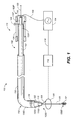
- FIG. 1 is a perspective view, partially in cross-section, of a cutting radio frequency (RF) catheter assembly in accordance with one example
- FIG. 2 is an enlarged perspective view of a distal end including an RF electrode of the RF catheter of FIG. 1;
- FIG. 3 is a cross-sectional view of a vessel assembly in accordance with one embodiment
- FIGS. 4, 5, and 6 are cross-sectional views of the vessel assembly of FIG. 3 at further stages during formation of a side opening in a graft material;
- FIG. 7 is an enlarged cross-sectional view of the vessel assembly of FIG. 6 including the side opening formed in the graft material;
- FIG. 8 is a cross-sectional view of the vessel assembly of FIG. 6 at a later stage of assembly illustrating the deployment of a branch stent-graft into the side opening in the graft material;
- FIG. 9 is a perspective view of an RF catheter having an RF electrode in accordance with another embodiment.
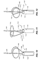
- FIGS. 10, 11 and 12 are perspective views of RF catheters having RF electrodes in accordance with various embodiments.
- RF power is applied to a circular RF electrode 106 creating a localized knife which is useful in cutting a side opening 602 in a graft material 308 of a main stent-graft 306 in situ.
- side opening 602 is formed by the applied RF power and the associated plasma discharge, side opening 602 is formed with a minimal application of force to graft material 308.
- the side opening is circular and has a fused edge.
- a side opening edge 704 defines side opening 602 in graft material 308.
- side opening edge 704 is circular in shape, i.e., is a circle. Accordingly, side opening edge 704 resists tearing of graft material 308 at side opening 602 compared to a rent where tearing force is concentrated at the graft material at the ends of the rent.
- side opening edge 704 is fused, i.e., the fibers, sometimes called yarn, of graft material 308 are melted together at side opening edge 704, as compared to the frayed edges of a rent or cut. Accordingly, tattering of side opening edge 704 is avoided. Further, the fused and circular side opening edge 704 applies even pressure to a branch stent-graft inserted in side opening 602 thus avoiding damage or destruction to the branch stent-graft.
- FIG. 1 is a perspective view, partially in cross-section, of a cutting radio frequency (RF) catheter assembly 100 including an RF catheter 102 and an RF power supply 104 in accordance with one example.
- RF catheter 102 includes a proximal end 102P and a distal end 102D.
- proximal end 102P of RF catheter 102 is referenced with respect to the operator's handle, i.e., handle 116.
- FIG. 2 is an enlarged perspective view of distal end 102D including an RF electrode 106 of RF catheter 102 of FIG. 1.
- RF electrode 106 is in the shape of a closed circle, i.e., is circular, sometimes called a continuous hoop, a continuous loop, or an unbroken circle.
- the diameter of RF electrode 106 is in the range of 5 mm to 7 mm, e.g., is 7 mm.
- RF electrode 106 is formed of an electrically conductive material.
- RF electrode 106 is formed of a super elastic memory material, e.g., nitinol, shape set into a circular loop.
- RF electrode 106 is formed of a radiopaque material to aid in visualization of RF electrode 106 using an imaging process, for example, so that RF electrode 106 is visible using x-rays.
- radiopaque materials of which RF electrode 106 is formed include platinumiridium, tantalum, and/or gold.
- RF electrode 106 is supported by and / or electrically connected to an RF conductor 108.
- RF conductor 108 is formed of the same material as RF electrode 106.
- RF electrode 106 and RF conductor 108 are integral, i.e., are a single piece and not a plurality of separate pieces connected together.
- RF conductor 108 is attached to RF electrode 106, e.g., by welding.
- RF conductor 108 includes a dielectric coating, e.g., RF conductor 108 is electrically conductive metal covered with a dielectric material such as a silicone elastomer.
- RF conductor 108 extends proximally from RF electrode 106 and into a distal end 110D of an inner member 110, sometimes called a cutting catheter shaft. RF conductor 108 extends through the length of inner member 110 and exits at a proximal end 110P of inner member 110.
- RF conductor 108 is electrically connected to RF power supply 104.
- RF power supply 104 supplies RF power to RF conductor 108 and thus to RF electrode 106.
- RF power supply 104 operates in the 500 kHz to 2 MHz frequency range. In one example, the frequency at which RF power supply 104 operates is greater than the threshold for excitation of tissue to avoid tissue excitation.
- the power output of RF power supply 104 is in the range of 50 to 200 watts.
- RF power supply 104 is a Pfizer Valley Lab Cautery RF generator although any one of a number of RF generators can be used. Although particular frequency and power output ranges are provided, these are illustrative only.
- RF power supply 104 is also electrically connected to a counter electrode 112, sometimes called the ground or common electrode, by a counter electrode conductor 114.
- counter electrode 112 e.g., a conductive metal plate (stainless steel), is electrically connected to the patient for example, using an electrically conductive gel.
- Counter electrode 112 forms the counter electrode for RF electrode 106 thus completing the circuit.
- RF catheter 102 further includes a handle 116.
- Proximal end 110P of inner member 110 is located at a guide wire port 118 of handle 116.
- Inner member 110 is a hollow tubular member and defines a guide wire lumen therein.
- a guide wire 120 e.g., a 0.014 inch guidewire, enters the guide wire lumen of inner member 110 at distal end 110D, extends through the length of inner member 110 inside of the guide wire lumen, and exits proximal end 110P of inner member 110 at guide wire port 118.
- guide wire 120 includes a dielectric coating or is formed of a dielectric material to prevent electrical coupling of RF power from RF electrode 106 to guide wire 120.
- guide wire 120 is retracted into distal end 110D of inner member 110 prior to coupling RF power to RF electrode 106.
- guide wire 120 includes a catching structure 121 (corkscrew like shaped structure) at a distal end 120D of guide wire 120.
- guide wire 120 includes a super elastic memory material, e.g., nitinol, at distal end 120D, which takes the shape of catching structure 121.
- catching structure 121 catches the flap of graft material cut from the graft material by RF electrode 106.
- a guide wire similar to guide wire 120 is formed without a catching structure 121.
- RF catheter 102 further includes a retractable sheath 122 for delivering RF electrode 106.
- a proximal end 122P of sheath 122 is located within handle 116.
- Proximal end 122P is connected to a thumb slider 124, sometimes called an actuation button.
- Thumb slider 124 extends from proximal end 122P of sheath 122 inside of handle 116 through a longitudinal slit 126 to the outside of handle 116. Thumb slider 124 is retracted and advanced relative to handle 116 thus retracting and advancing (moving) sheath 122 relative to inner member 110.
- proximal end 110P of inner member 110 is connected to handle 116 at guide wire port 118 and thus inner member 110 is fixed relative to handle 116.
- Sheath 122 is a hollow tubular member and includes an inner member lumen in which inner member 110 is located. As discussed further below, in one example, RF electrode 106 is initially radially constrained inside of sheath 122. Sheath 122 is retracted by retracting thumb slider 124 thus exposing RF electrode 106, which self-expands, e.g., into the shape illustrated in FIG. 1.
- sheath 122 is advanced by advancing thumb slider 124. During advancement, distal end 122D of sheath 122 collapses and covers RF electrode 106.
- inner member 110 includes a tubular RF electrode extension portion 128 (shown in dotted lines) which extends distally past the point where RF conductor 108 exits inner member 110. Accordingly, RF electrode 106 is collapsed within the annular space between RF electrode extension portion 128 of inner member 110 and sheath 122.
- Cutting RF catheter assembly 100 further includes a delivery catheter 130.
- delivery catheter 130 is a steerable guiding catheter.
- delivery catheter 130 is a pre-curved catheter having a bend 132, e.g., a 90 degree bend, formed at a distal end 130D of delivery catheter 130.
- Delivery catheter 130 is a hollow tubular member which defines a lumen. Inner member 110 including RF electrode 106 and sheath 122 are advanced through the lumen of delivery catheter 130. Delivery catheter 130 directs RF electrode 106, e.g., at a 90 degree angle from the length of RF catheter 102.
- Delivery catheter 130 includes a radiopaque marker 134 at distal end 130D of delivery catheter 130. Radiopaque marker 134 allows the location of distal end 130D to be visualized using any one of a number imaging techniques. In another example, delivery catheter 130 is not used.
- an RF catheter similar to RF catheter 102 is formed without sheath 122.
- inner member 110 and thus RF electrode 106 are advanced through delivery catheter 130.
- RF electrode 106 self expands. Further, after use of RF electrode 106 as discussed further below, RF electrode 106 is pulled back into distal end 130D, which collapses and covers RF electrode 106.
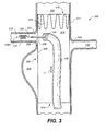
- FIG. 3 is a cross-sectional view of a vessel assembly 300 in accordance with one embodiment.
- a main vessel 302 e.g., the aorta
- a main stent-graft 306 e.g., an abdominal aortic stent-graft, is deployed into main vessel 302 to exclude aneurysm 304.
- main stent-graft 306 sometimes called a prosthesis, includes a graft material 308 and a stent ring 310.
- Graft material 308 is cylindrical having a longitudinal axis L1.
- Graft material 308 includes an upper, e.g., first, primary opening 312 and a lower, e.g., second, primary opening 314 at the ends of graft material 308. Graft material 308 defines a lumen 316 longitudinally extending from upper primary opening 312 to lower primary opening 314. During use, fluid, e.g., blood, flows through lumen 316 and more generally through graft material 308 thus excluding aneurysm 304.
- fluid e.g., blood
- Stent ring 310 is connected to main stent-graft 306, for example, with stitching.
- Stent ring 310 is a radially expandable reinforcement structure that self expands into a vessel wall 317 of main vessel 302 thus anchoring main stent-graft 306 in place.
- a main stent-graft similar to main stent-graft 306 is formed with a plurality of stent rings or other radially expandable reinforcement structures.
- main vessel 302 Emanating from main vessel 302 is a first branch vessel 318 and a second branch vessel 320.
- the location of branch vessels 318, 320 vary from patient to patient.
- side openings corresponding to ostiums 322, 324 of branch vessel 318, 320, respectively, are formed in graft material 308 in situ after main stent-graft 306 is deployed within main vessel 302 as set forth below.
- delivery catheter 130 is advanced to the location of branch vessel 318.
- Radiopaque marker 134 is used to facilitate this positioning of delivery catheter 130.
- Distal end 130D is oriented radially, e.g., at a 90 degree angle, relative to longitudinal axis L1 and thus points at graft material 308 and within ostium 322 of branch vessel 318.
- a hollow needle 326 e.g., similar to a hypodermic needle, is advanced through the lumen of delivery catheter 130. Needle 326 pierces graft material 308 adjacent ostium 322 thus forming a small, e.g., first, opening 328 in graft material 308. Small opening 328 is sometimes called a central opening.
- Guide wire 120 is advanced through the lumen of needle 326 through graft material 308 and deployed into branch vessel 318.
- guide wire 120 forms catching structure 121 at distal end 120D of guide wire 120.
- catching structure 121 is formed of a super elastic memory material, e.g., nitinol, and thus assumes the shape of catching structure 121 as guide wire 120 is fed out of needle 326.
- the lateral span of the catching structure 121 is larger in diameter than small opening 328.
- guide wire 120 including catching structure 121 are used to catch the flap cut from graft material 308 and remove the flap from the patient.
- Catching structure 121 is shown as a helix but can be formed in any one of a number of shapes.
- Needle 326 is retracted leaving guide wire 120 extending through small opening 328.
- FIGS. 4 and 5 are cross-sectional views of vessel assembly 300 of FIG. 3 at further stages during formation of a side opening in graft material 308.
- RF catheter 102 is advanced over the guidewire120 through the lumen of delivery catheter 130 to graft material 308 adjacent (opposite) ostium 322 of branch vessel 318.
- RF electrode 106 self expands into an expanded circular shape as shown in FIG. 5.
- FIG. 6 is a cross-sectional view of vessel assembly 300 at a further stage during formation of a side opening in graft material 308.
- RF electrode 106 is advanced to be adjacent to or in contact with graft material 308 at ostium 322 of branch vessel 318.
- RF power is applied to RF electrode 106 thus cutting graft material 308 in a shape corresponding to RF electrode 106 and forming a side opening 602 in graft material 308.
- side opening 602 is a 5 mm or 7 mm circular opening.
- RF electrode 106 upon application of RF power to RF electrode 106, the fluid, e.g., blood, surrounding RF electrode 106 becomes heated until an electrical plasma is generated. This plasma, sometimes called a plasma discharge, vaporizes the graft material 308 directly adjacent RF electrode 106.
- This plasma sometimes called a plasma discharge, vaporizes the graft material 308 directly adjacent RF electrode 106.
- an arc between RF electrode 106 and graft material 308 cuts graft material 308.
- RF electrode 106 itself becomes heated by the RF power and thus thermally cuts graft material 308.
- side opening 602 is formed in graft material 308. It accordance with this example, RF electrode 106 is held stationery and thus side opening 602 is formed without application of force to graft material 308.
- RF electrode 106 upon application of RF power to RF electrode 106, RF electrode 106 is advanced to pass through graft material 308 slightly. However, as the cutting of graft material 308 is performed by the RF power coupled to RF electrode 106, side opening 602 is formed with a minimal application of force to graft material 308. Further, as discussed further below in reference to FIG. 7, the side opening edge of side opening 602 is fused graft material 308, i.e., has an absence of loose dangling fibers of graft material 308.
- FIG. 7 is an enlarged cross-sectional view of vessel assembly 300 of FIG. 6 including side opening 602 formed in graft material 308.
- RF electrode 106 is withdrawn from the patient.
- sheath 122 (FIG. 4) is advanced thus collapsing and covering RF electrode 106.
- RF catheter 102 is then retracted from delivery catheter 130.
- an annular shaped flap 702 cut from graft material 308 is held by guide wire 120. Further, catching structure 121 of guide wire 120 is larger in diameter than small opening 328 in flap 702 preventing flap 702 from sliding off of guide wire 120. Guide wire 120 including flap 702 are then withdrawn from the patient.
- graft material 308 now includes a side opening edge 704 formed when RF electrode 106 cut side opening 602 in graft material 308. More particularly, side opening edge 704 defines side opening 602 in graft material 308.
- side opening edge 704 is circular in shape, i.e., is a circle. Accordingly, side opening edge 704 resists tearing of graft material 308 at side opening 602 compared to a rent where tearing force is concentrated at the graft material at the ends of the rent.
- side opening edge 704 is fused, i.e., the fibers, sometimes called yarn, of graft material 308 are melted together at side opening edge 704 as compared to the frayed edges of a rent or cut. Accordingly, tattering of side opening edge 704 is avoided. Further, the fused and circular side opening edge 704 applies even pressure to a branch stent-graft such as that illustrated in FIG. 8 inserted in side opening 602 thus avoiding damage or destruction to the branch stent-graft.
- FIG. 8 is a cross-sectional view of vessel assembly 300 of FIG. 6 at a later stage of assembly illustrating the deployment of a branch stent-graft 802 into side opening 602 in graft material 308.
- branch stent-graft 802 is inserted into side opening 602 and extends into branch vessel 318.
- branch stent-graft 802 is radially constrained within a sheath (not shown) and positioned inside of side opening 602 and branch vessel 318. The sheath is retracted, uncovering branch stent-graft 802, which self expands into position.
- branch stent-graft 802 can be deployed using other techniques.
- branch stent-graft 802 includes a flange 804 or other locking structure to lock branch stent-graft 802 to main stent-graft 306.
- branch stent-graft 802 self expands into side opening edge 704 to lock branch stent-graft to main stent-graft 306. The fused and circular side opening edge 704 applies even pressure to branch stent-graft 802 thus avoiding damage or destruction to branch stentgraft 802.
- Branch vessel graft material 806 of branch stent-graft 802 extends from side opening 602 and into branch vessel 318.
- a stent ring 808 anchors the end of branch vessel graft material 806 in branch vessel 318 and generally maintains patency of branch vessel 318.
- fluid flows from lumen 316 of main stent-graft 306 through the lumen of branch stent-graft 802 and into branch vessel 318.
- the above operations are performed to form a side opening corresponding to second branch vessel 320 and a second branch stent-graft is inserted therein to perfuse second branch vessel 320.
- guide wire 120 (absent catching structure 121 in accordance with this example) is retracted prior to the application of RF power to RF electrode 106.
- delivery catheter 130 is not used.
- guide wire 120 is deployed after side opening 602 is formed.
- Branch stent-graft 802 is advanced over guide wire 120 in accordance with this example.
- small opening 328 is not formed.
- side opening 602 is formed in a single operation by application of RF power to RF electrode 106.
- an RF electrode such as that described in FIG. 9 is used to form small opening 328.
- FIG. 9 is a perspective view of an RF catheter 102A having an RF electrode 106A in accordance with another embodiment.
- RF catheter 102A includes an inner member 110A. Located at a distal end 110D of inner member 110A is RF electrode 106A.
- RF electrode 106A is electrically connected to an RF conductor 108A (indicated by the dashed lines) which extends along the length of inner member 110A.
- RF electrode 106A is cone shaped, i.e., conical, in accordance with this example. More particularly, RF electrode 106A increases in diameter from a distal end 106D to a proximal end 106P of RF electrode 106A. Illustratively, the maximum outer diameter of RF electrode at proximal end 106P is 3 mm.
- Inner member 110A is hollow and includes a guide wire lumen formed therein. As shown, a guide wire 120A exits inner member 110A at distal end 110D.
- RF electrode 106A has an opening formed through the center through which guide wire 120A passes. For example, RF electrode 106A sits on inner member 110A, which provides the dielectric between RF electrode 106A and guide wire 120A.
- These dielectrics can be comprised of temperature resistant plastics or ceramics.
- RF catheter 102A further includes a delivery catheter 130A similar to delivery catheter 130 of FIG. 1 and so is not discussed again in detail.
- RF power is applied to RF electrode 106A to form an opening similar to small opening 328 in a graft material.
- the graft material is vaporized such that the opening is formed in the graft material without creation of a loose flap of graft material.
- FIG. 10 is a perspective view of an RF catheter 102B having an RF electrode 106B in accordance with another embodiment.
- RF catheter 102B includes an inner member 110B.
- inner member 110B is a coaxial structure including an inner tube 1030 and an outer tube 1032, e.g., shrink tubing.
- RF conductor 108B extends along the length of inner member 110B in the annular space between inner tube 1030 and outer tube 1032.
- RF electrode 106B is in a circular shape of an open circle, sometimes called a circular spiral, or a broken or noncontinuous circle.
- RF conductor 108B and RF electrode 106B are parts of a single integral wire.
- Inner member 110B is hollow and includes a guide wire lumen formed therein. As shown, a guide wire 120B exits inner member 110B at distal end 110D.
- FIG. 11 is a perspective view of an RF catheter 102C having an RF electrode 106C in accordance with another embodiment.
- RF catheter 102C includes an inner member 110C.
- inner member 110C is a coaxial structure including an inner tube 1130 and an outer tube 1132, e.g., shrink tubing.
- RF conductor 108C is formed by two side-by-side conductors 1140, 1142 extends along the length of inner member 110C in the annular space between inner tube 1130 and outer tube 1132.
- RF electrode 106C is in an open circular shape of an open circle. More particularly, RF electrode 106C is a circular spiral where the distal end of the circular spiral extends proximally back into inner member 110C.
- conductors 1140, 1142 sometimes called a first conductor and a second conductor, both extend proximally from the open circular shape of RF electrode 106C at the same point along the circle.
- conductors 1140, 1142 and RF electrode 106C are parts of a single integral wire.
- Inner member 110C is hollow and includes a guide wire lumen formed therein. As shown, a guide wire 120C exits inner member 110C at distal end 110D.
- FIG. 12 is a perspective view of an RF catheter 102E having an RF electrode 106E in accordance with another embodiment.
- RF catheter 102E includes an inner member 110E.
- inner member 110E is a coaxial structure including an inner tube 1230 and an outer tube 1232, e.g., shrink tubing.
- RF conductor 108E is formed by two side-by-side conductors 1240, 1242 extends along the length of inner member 110E in the annular space between inner tube 1230 and outer tube 1232.
- RF electrode 106E is in an open circular shape. More particularly, RF electrode 106E is a circular spiral where the distal end of the circular spiral extends proximally back into inner member 110E.
- conductors 1240, 1242 both extend proximally from the open circular shape of RF electrode 106E at different point along the circle.
- conductors 1240, 1242 and RF electrode 106E are parts of a single integral wire.
- Inner member 110E is hollow and includes a guide wire lumen formed therein. As shown, a guide wire 120E exits inner member 110E at distal end 110D.
Landscapes
- Health & Medical Sciences (AREA)
- Life Sciences & Earth Sciences (AREA)
- Surgery (AREA)
- Engineering & Computer Science (AREA)
- Plasma & Fusion (AREA)
- Medical Informatics (AREA)
- Otolaryngology (AREA)
- Physics & Mathematics (AREA)
- Cardiology (AREA)
- Biomedical Technology (AREA)
- Heart & Thoracic Surgery (AREA)
- Nuclear Medicine, Radiotherapy & Molecular Imaging (AREA)
- Molecular Biology (AREA)
- Animal Behavior & Ethology (AREA)
- General Health & Medical Sciences (AREA)
- Public Health (AREA)
- Veterinary Medicine (AREA)
- Surgical Instruments (AREA)
Abstract
Description
- The present invention relates to an intra-vascular device and method. More particularly, the present invention relates to a device for treatment of intra-vascular diseases. Aspects of the present invention relate to methods of forming a side opening e.g. in a graft material, and to radio frequency (RF) catheter assemblies, especially for cutting.
- A conventional main (vessel) stent-graft typically includes a radially expandable reinforcement structure, formed from a plurality of annular stent rings, and a cylindrically shaped layer of graft material, sometimes called graft cloth, defining a lumen to which the stent rings are coupled. Main stent-grafts are well known for use in tubular shaped human vessels.
- To illustrate, endovascular aneurysmal exclusion is a method of using a main stent-graft to exclude pressurized fluid flow from the interior of an aneurysm, thereby reducing the risk of rupture of the aneurysm and the associated invasive surgical intervention.
- Main stent-grafts with custom side openings are sometimes fabricated to accommodate the particular vessel structure of each individual patient. Specifically, as the location of branch vessels emanating from a main vessel, e.g., having the aneurysm, varies from patient to patient, main stent-grafts are fabricated with side openings customized to match the position of the branch vessels of the particular patient. However, custom fabrication of main stent-grafts is relatively expensive and time consuming.
- To avoid custom fabrication of main stent-grafts, side openings in the main stentgraft may be formed in situ. Illustratively, the main stent-graft is placed in the main vessel, e.g., the aorta, to exclude an aneurysm. Fenestrations may be made in situ to correspond to adjacent branches.
- The graft material of the main stent-graft is pierced with a needle at the ostium of a branch vessel, e.g., the renal artery, emanating from the main vessel. An expandable balloon is then inserted in the needle perforation in the graft material of the main stentgraft.
- A fenestration is typically initiated with a small needle perforation of the graft cloth. The perforation must be enlarged with a conical dialator
- However, considerable force is required to expand the balloon and tear the graft material. The application of such a considerable force is difficult to control thus leads to unpredictability in the tear of the graft material or other complications. Further, the branch stent-graft tends to propagate the rent (a split or tear) in the graft material over time. Further, the edge of the rent fractured the branch stent-graft depending upon the particular application. Finally, the edge of the rent was a fray of loose fibers of the graft material, which tended to unwind over time.
- In view of the above, a method of forming a side opening in a graft material according to independent claim 1, and a cutting radio frequency catheter assemblies according to independent claims 21 and 38 are provided. Further advantages, features, aspects and details of the invention are evident from the dependent claims, the description and the drawings.
- In accordance with one example, RF power is applied to a circular RF electrode cutting a side opening in a graft material of a main stent-graft in situ. As the side opening is formed by the applied RF power and possibly by an associated plasma discharge, the side opening is formed with a minimal application of force to the graft material.
- The side opening may be defined by a side opening edge of the graft material. The side opening edge may be circular. Accordingly, the side opening edge may resist tearing of the graft material at the side opening compared to a rent where tearing force is concentrated at the graft material at the ends of the rent.
- Further, the side opening edge may be fused, i.e., the graft material may be melted together at the side opening edge, as compared to the frayed edges of a rent or cut. Accordingly, tattering of the side opening edge may be avoided. Further, the fused and circular side opening edge generally applies even pressure to a branch stent-graft inserted in the side opening thus avoiding damage or destruction to the branch stent-graft.
- The invention is also directed to apparatuses for carrying out the disclosed methods and including apparatus parts for performing each described method steps. These method steps may be performed by way of hardware components, a computer programmed by appropriate software, by any combination of the two or in any other manner. Furthermore, the invention is also directed to methods by which the described apparatus operates. It includes method steps for carrying out every function of the apparatus or manufacturing every part of the apparatus.
- Embodiments are best understood by reference to the following detailed description when read in conjunction with the accompanying drawings, wherein
- FIG. 1 is a perspective view, partially in cross-section, of a cutting radio frequency (RF) catheter assembly in accordance with one example;
- FIG. 2 is an enlarged perspective view of a distal end including an RF electrode of the RF catheter of FIG. 1;
- FIG. 3 is a cross-sectional view of a vessel assembly in accordance with one embodiment;
- FIGS. 4, 5, and 6 are cross-sectional views of the vessel assembly of FIG. 3 at further stages during formation of a side opening in a graft material;
- FIG. 7 is an enlarged cross-sectional view of the vessel assembly of FIG. 6 including the side opening formed in the graft material;
- FIG. 8 is a cross-sectional view of the vessel assembly of FIG. 6 at a later stage of assembly illustrating the deployment of a branch stent-graft into the side opening in the graft material;
- FIG. 9 is a perspective view of an RF catheter having an RF electrode in accordance with another embodiment; and
- FIGS. 10, 11 and 12 are perspective views of RF catheters having RF electrodes in accordance with various embodiments.
- Common reference numerals are used throughout the drawings and detailed description to indicate like elements.
- In accordance with one example, referring to FIG. 6, RF power is applied to a
circular RF electrode 106 creating a localized knife which is useful in cutting aside opening 602 in agraft material 308 of a main stent-graft 306 in situ. Asside opening 602 is formed by the applied RF power and the associated plasma discharge,side opening 602 is formed with a minimal application of force tograft material 308. In an example, the side opening is circular and has a fused edge. - Referring now to FIG. 7, a side
opening edge 704 definesside opening 602 ingraft material 308. In one example, sideopening edge 704 is circular in shape, i.e., is a circle. Accordingly, sideopening edge 704 resists tearing ofgraft material 308 atside opening 602 compared to a rent where tearing force is concentrated at the graft material at the ends of the rent. - Further, side
opening edge 704 is fused, i.e., the fibers, sometimes called yarn, ofgraft material 308 are melted together at sideopening edge 704, as compared to the frayed edges of a rent or cut. Accordingly, tattering of sideopening edge 704 is avoided. Further, the fused and circular sideopening edge 704 applies even pressure to a branch stent-graft inserted inside opening 602 thus avoiding damage or destruction to the branch stent-graft. - More particularly, FIG. 1 is a perspective view, partially in cross-section, of a cutting radio frequency (RF)
catheter assembly 100 including anRF catheter 102 and anRF power supply 104 in accordance with one example.RF catheter 102 includes aproximal end 102P and adistal end 102D. As used herein,proximal end 102P ofRF catheter 102 is referenced with respect to the operator's handle, i.e., handle 116. - FIG. 2 is an enlarged perspective view of
distal end 102D including anRF electrode 106 ofRF catheter 102 of FIG. 1. - Referring now to FIGS. 1 and 2 together,
RF electrode 106 is in the shape of a closed circle, i.e., is circular, sometimes called a continuous hoop, a continuous loop, or an unbroken circle. In various examples, the diameter ofRF electrode 106 is in the range of 5 mm to 7 mm, e.g., is 7 mm. Generally,RF electrode 106 is formed of an electrically conductive material. - In one example,
RF electrode 106 is formed of a super elastic memory material, e.g., nitinol, shape set into a circular loop. In other examples,RF electrode 106 is formed of a radiopaque material to aid in visualization ofRF electrode 106 using an imaging process, for example, so thatRF electrode 106 is visible using x-rays. Illustrative examples of radiopaque materials of whichRF electrode 106 is formed include platinumiridium, tantalum, and/or gold. -
RF electrode 106 is supported by and / or electrically connected to anRF conductor 108. Illustratively,RF conductor 108 is formed of the same material asRF electrode 106. In one specific example,RF electrode 106 andRF conductor 108 are integral, i.e., are a single piece and not a plurality of separate pieces connected together. In another example,RF conductor 108 is attached toRF electrode 106, e.g., by welding. Further, to avoid plasma generation fromRF conductor 108, in one embodiment,RF conductor 108 includes a dielectric coating, e.g.,RF conductor 108 is electrically conductive metal covered with a dielectric material such as a silicone elastomer. -
RF conductor 108 extends proximally fromRF electrode 106 and into adistal end 110D of aninner member 110, sometimes called a cutting catheter shaft.RF conductor 108 extends through the length ofinner member 110 and exits at aproximal end 110P ofinner member 110. -
RF conductor 108 is electrically connected toRF power supply 104. During use,RF power supply 104 supplies RF power toRF conductor 108 and thus toRF electrode 106. Illustratively,RF power supply 104 operates in the 500 kHz to 2 MHz frequency range. In one example, the frequency at whichRF power supply 104 operates is greater than the threshold for excitation of tissue to avoid tissue excitation. - As another example, the power output of
RF power supply 104 is in the range of 50 to 200 watts. For example,RF power supply 104 is a Pfizer Valley Lab Cautery RF generator although any one of a number of RF generators can be used. Although particular frequency and power output ranges are provided, these are illustrative only. -
RF power supply 104 is also electrically connected to acounter electrode 112, sometimes called the ground or common electrode, by acounter electrode conductor 114. During use,counter electrode 112, e.g., a conductive metal plate (stainless steel), is electrically connected to the patient for example, using an electrically conductive gel.Counter electrode 112 forms the counter electrode forRF electrode 106 thus completing the circuit. -
RF catheter 102 further includes ahandle 116.Proximal end 110P ofinner member 110 is located at aguide wire port 118 ofhandle 116.Inner member 110 is a hollow tubular member and defines a guide wire lumen therein. Aguide wire 120, e.g., a 0.014 inch guidewire, enters the guide wire lumen ofinner member 110 atdistal end 110D, extends through the length ofinner member 110 inside of the guide wire lumen, and exitsproximal end 110P ofinner member 110 atguide wire port 118. In one example,guide wire 120 includes a dielectric coating or is formed of a dielectric material to prevent electrical coupling of RF power fromRF electrode 106 to guidewire 120. In another example, as discussed further below,guide wire 120 is retracted intodistal end 110D ofinner member 110 prior to coupling RF power toRF electrode 106. - In one example,
guide wire 120 includes a catching structure 121 (corkscrew like shaped structure) at adistal end 120D ofguide wire 120. Illustratively,guide wire 120 includes a super elastic memory material, e.g., nitinol, atdistal end 120D, which takes the shape of catchingstructure 121. As discussed further below, catchingstructure 121 catches the flap of graft material cut from the graft material byRF electrode 106. However, in another example, a guide wire similar to guidewire 120 is formed without a catchingstructure 121. -
RF catheter 102 further includes aretractable sheath 122 for deliveringRF electrode 106. Aproximal end 122P ofsheath 122 is located withinhandle 116.Proximal end 122P is connected to athumb slider 124, sometimes called an actuation button.Thumb slider 124 extends fromproximal end 122P ofsheath 122 inside ofhandle 116 through alongitudinal slit 126 to the outside ofhandle 116.Thumb slider 124 is retracted and advanced relative to handle 116 thus retracting and advancing (moving)sheath 122 relative toinner member 110. Recall thatproximal end 110P ofinner member 110 is connected to handle 116 atguide wire port 118 and thusinner member 110 is fixed relative to handle 116. -
Sheath 122 is a hollow tubular member and includes an inner member lumen in whichinner member 110 is located. As discussed further below, in one example,RF electrode 106 is initially radially constrained inside ofsheath 122.Sheath 122 is retracted by retractingthumb slider 124 thus exposingRF electrode 106, which self-expands, e.g., into the shape illustrated in FIG. 1. - After using
RF electrode 106 to form a side opening in the graft material of the main stent-graft as discussed below,sheath 122 is advanced by advancingthumb slider 124. During advancement,distal end 122D ofsheath 122 collapses and coversRF electrode 106. - In one embodiment,
inner member 110 includes a tubular RF electrode extension portion 128 (shown in dotted lines) which extends distally past the point whereRF conductor 108 exitsinner member 110. Accordingly,RF electrode 106 is collapsed within the annular space between RFelectrode extension portion 128 ofinner member 110 andsheath 122. - Cutting
RF catheter assembly 100 further includes adelivery catheter 130. In one example,delivery catheter 130 is a steerable guiding catheter. It another example,delivery catheter 130 is a pre-curved catheter having abend 132, e.g., a 90 degree bend, formed at adistal end 130D ofdelivery catheter 130. -
Delivery catheter 130 is a hollow tubular member which defines a lumen.Inner member 110 includingRF electrode 106 andsheath 122 are advanced through the lumen ofdelivery catheter 130.Delivery catheter 130 directsRF electrode 106, e.g., at a 90 degree angle from the length ofRF catheter 102. -
Delivery catheter 130 includes aradiopaque marker 134 atdistal end 130D ofdelivery catheter 130.Radiopaque marker 134 allows the location ofdistal end 130D to be visualized using any one of a number imaging techniques. In another example,delivery catheter 130 is not used. - In one example, an RF catheter similar to
RF catheter 102 is formed withoutsheath 122. In accordance with this example,inner member 110 and thusRF electrode 106 are advanced throughdelivery catheter 130. AsRF electrode 106 exitsdistal end 130D ofdelivery catheter 130,RF electrode 106 self expands. Further, after use ofRF electrode 106 as discussed further below,RF electrode 106 is pulled back intodistal end 130D, which collapses and coversRF electrode 106. - FIG. 3 is a cross-sectional view of a
vessel assembly 300 in accordance with one embodiment. Referring now to FIG. 3, amain vessel 302, e.g., the aorta, includes ananeurysm 304. A main stent-graft 306, e.g., an abdominal aortic stent-graft, is deployed intomain vessel 302 to excludeaneurysm 304. - In accordance with this example, main stent-
graft 306, sometimes called a prosthesis, includes agraft material 308 and astent ring 310.Graft material 308 is cylindrical having a longitudinal axis L1. -
Graft material 308 includes an upper, e.g., first,primary opening 312 and a lower, e.g., second,primary opening 314 at the ends ofgraft material 308.Graft material 308 defines alumen 316 longitudinally extending from upperprimary opening 312 to lowerprimary opening 314. During use, fluid, e.g., blood, flows throughlumen 316 and more generally throughgraft material 308 thus excludinganeurysm 304. -
Stent ring 310 is connected to main stent-graft 306, for example, with stitching.Stent ring 310 is a radially expandable reinforcement structure that self expands into avessel wall 317 ofmain vessel 302 thus anchoring main stent-graft 306 in place. Although only asingle stent ring 310 is set forth, in other examples, a main stent-graft similar to main stent-graft 306 is formed with a plurality of stent rings or other radially expandable reinforcement structures. - Emanating from
main vessel 302 is afirst branch vessel 318 and asecond branch vessel 320. The location ofbranch vessels branch vessel graft material 308 in situ after main stent-graft 306 is deployed withinmain vessel 302 as set forth below. - To form a side opening in
graft material 308 corresponding to (at)branch vessel 318, e.g., a renal artery (RA) or a superior mesenteric artery (SMA), sometimes called a visceral branch,delivery catheter 130 is advanced to the location ofbranch vessel 318.Radiopaque marker 134 is used to facilitate this positioning ofdelivery catheter 130.Distal end 130D is oriented radially, e.g., at a 90 degree angle, relative to longitudinal axis L1 and thus points atgraft material 308 and withinostium 322 ofbranch vessel 318. - A
hollow needle 326, e.g., similar to a hypodermic needle, is advanced through the lumen ofdelivery catheter 130.Needle 326 piercesgraft material 308adjacent ostium 322 thus forming a small, e.g., first, opening 328 ingraft material 308.Small opening 328 is sometimes called a central opening. -
Guide wire 120 is advanced through the lumen ofneedle 326 throughgraft material 308 and deployed intobranch vessel 318. In accordance with this example, asguide wire 120 exits needle 326,guide wire 120forms catching structure 121 atdistal end 120D ofguide wire 120. Illustratively, catchingstructure 121 is formed of a super elastic memory material, e.g., nitinol, and thus assumes the shape of catchingstructure 121 asguide wire 120 is fed out ofneedle 326. - Generally, the lateral span of the catching
structure 121 is larger in diameter thansmall opening 328. As discussed further below,guide wire 120 including catchingstructure 121 are used to catch the flap cut fromgraft material 308 and remove the flap from the patient. - Catching
structure 121 is shown as a helix but can be formed in any one of a number of shapes. -
Needle 326 is retracted leavingguide wire 120 extending throughsmall opening 328. - FIGS. 4 and 5 are cross-sectional views of
vessel assembly 300 of FIG. 3 at further stages during formation of a side opening ingraft material 308. Referring now to FIGS. 4 and 5 together,RF catheter 102 is advanced over the guidewire120 through the lumen ofdelivery catheter 130 to graft material 308 adjacent (opposite)ostium 322 ofbranch vessel 318. - As indicated by
arrow 402 in FIG. 4,sheath 122 is retracted thus uncovering RF (loop)electrode 106. Upon being uncovered,RF electrode 106 self expands into an expanded circular shape as shown in FIG. 5. - FIG. 6 is a cross-sectional view of
vessel assembly 300 at a further stage during formation of a side opening ingraft material 308. As shown in FIG. 6,RF electrode 106 is advanced to be adjacent to or in contact withgraft material 308 atostium 322 ofbranch vessel 318. RF power is applied toRF electrode 106 thus cuttinggraft material 308 in a shape corresponding toRF electrode 106 and forming aside opening 602 ingraft material 308. In various examples,side opening 602 is a 5 mm or 7 mm circular opening. - It is believed that upon application of RF power to
RF electrode 106, the fluid, e.g., blood, surroundingRF electrode 106 becomes heated until an electrical plasma is generated. This plasma, sometimes called a plasma discharge, vaporizes thegraft material 308 directlyadjacent RF electrode 106. Although one theory of operation is set forth, this example is not limited to this particular theory, and other modes of operation are possible. For example, an arc betweenRF electrode 106 andgraft material 308cuts graft material 308. In another example,RF electrode 106 itself becomes heated by the RF power and thus thermally cutsgraft material 308. - In one example, upon application of RF power to
RF electrode 106,side opening 602 is formed ingraft material 308. It accordance with this example,RF electrode 106 is held stationery and thus side opening 602 is formed without application of force to graftmaterial 308. - In another example, upon application of RF power to
RF electrode 106,RF electrode 106 is advanced to pass throughgraft material 308 slightly. However, as the cutting ofgraft material 308 is performed by the RF power coupled toRF electrode 106,side opening 602 is formed with a minimal application of force to graftmaterial 308. Further, as discussed further below in reference to FIG. 7, the side opening edge ofside opening 602 is fusedgraft material 308, i.e., has an absence of loose dangling fibers ofgraft material 308. - FIG. 7 is an enlarged cross-sectional view of
vessel assembly 300 of FIG. 6 includingside opening 602 formed ingraft material 308. Referring now to FIG. 6 and 7 together, after coupling of RF power toRF electrode 106 and formation ofside opening 602,RF electrode 106 is withdrawn from the patient. Illustratively, sheath 122 (FIG. 4) is advanced thus collapsing and coveringRF electrode 106.RF catheter 102 is then retracted fromdelivery catheter 130. - As shown in FIG. 7, an annular shaped
flap 702 cut fromgraft material 308 is held byguide wire 120. Further, catchingstructure 121 ofguide wire 120 is larger in diameter thansmall opening 328 inflap 702 preventingflap 702 from sliding off ofguide wire 120.Guide wire 120 includingflap 702 are then withdrawn from the patient. - As also shown in FIG. 7,
graft material 308 now includes aside opening edge 704 formed whenRF electrode 106cut side opening 602 ingraft material 308. More particularly,side opening edge 704 definesside opening 602 ingraft material 308. - In one example,
side opening edge 704 is circular in shape, i.e., is a circle. Accordingly,side opening edge 704 resists tearing ofgraft material 308 atside opening 602 compared to a rent where tearing force is concentrated at the graft material at the ends of the rent. - Further,
side opening edge 704 is fused, i.e., the fibers, sometimes called yarn, ofgraft material 308 are melted together atside opening edge 704 as compared to the frayed edges of a rent or cut. Accordingly, tattering ofside opening edge 704 is avoided. Further, the fused and circularside opening edge 704 applies even pressure to a branch stent-graft such as that illustrated in FIG. 8 inserted inside opening 602 thus avoiding damage or destruction to the branch stent-graft. - FIG. 8 is a cross-sectional view of
vessel assembly 300 of FIG. 6 at a later stage of assembly illustrating the deployment of a branch stent-graft 802 intoside opening 602 ingraft material 308. As shown in FIG. 8, branch stent-graft 802 is inserted intoside opening 602 and extends intobranch vessel 318. Illustratively, branch stent-graft 802 is radially constrained within a sheath (not shown) and positioned inside ofside opening 602 andbranch vessel 318. The sheath is retracted, uncovering branch stent-graft 802, which self expands into position. However, branch stent-graft 802 can be deployed using other techniques. - In one example, branch stent-
graft 802 includes aflange 804 or other locking structure to lock branch stent-graft 802 to main stent-graft 306. In another example, branch stent-graft 802 self expands intoside opening edge 704 to lock branch stent-graft to main stent-graft 306. The fused and circularside opening edge 704 applies even pressure to branch stent-graft 802 thus avoiding damage or destruction to branchstentgraft 802. - Branch
vessel graft material 806 of branch stent-graft 802 extends fromside opening 602 and intobranch vessel 318. Astent ring 808 anchors the end of branchvessel graft material 806 inbranch vessel 318 and generally maintains patency ofbranch vessel 318. During use, fluid flows fromlumen 316 of main stent-graft 306 through the lumen of branch stent-graft 802 and intobranch vessel 318. In one example, the above operations are performed to form a side opening corresponding tosecond branch vessel 320 and a second branch stent-graft is inserted therein to perfusesecond branch vessel 320. - Although a particular sequence of operations are set forth above, in other examples, other sequences of operations are performed. For example, referring to FIG. 6, guide wire 120 (absent catching
structure 121 in accordance with this example) is retracted prior to the application of RF power toRF electrode 106. In another example,delivery catheter 130 is not used. - In another example,
guide wire 120 is deployed afterside opening 602 is formed. Branch stent-graft 802 is advanced overguide wire 120 in accordance with this example. - In another example, referring to FIG. 3,
small opening 328 is not formed. In accordance with this example, referring now to FIG. 6,side opening 602 is formed in a single operation by application of RF power toRF electrode 106. - In another example, referring to FIG. 3, to avoid the application of force required to pierce
graft material 308 withneedle 326, an RF electrode such as that described in FIG. 9 is used to formsmall opening 328. - FIG. 9 is a perspective view of an
RF catheter 102A having anRF electrode 106A in accordance with another embodiment. Referring now to FIG. 9,RF catheter 102A includes aninner member 110A. Located at adistal end 110D ofinner member 110A isRF electrode 106A.RF electrode 106A is electrically connected to anRF conductor 108A (indicated by the dashed lines) which extends along the length ofinner member 110A. -
RF electrode 106A is cone shaped, i.e., conical, in accordance with this example. More particularly,RF electrode 106A increases in diameter from adistal end 106D to aproximal end 106P ofRF electrode 106A. Illustratively, the maximum outer diameter of RF electrode atproximal end 106P is 3 mm. -
Inner member 110A is hollow and includes a guide wire lumen formed therein. As shown, aguide wire 120A exitsinner member 110A atdistal end 110D.RF electrode 106A has an opening formed through the center through whichguide wire 120A passes. For example,RF electrode 106A sits oninner member 110A, which provides the dielectric betweenRF electrode 106A and guidewire 120A. These dielectrics can be comprised of temperature resistant plastics or ceramics. -
RF catheter 102A further includes adelivery catheter 130A similar todelivery catheter 130 of FIG. 1 and so is not discussed again in detail. - Referring now to FIGS. 3 and 9 together, RF power is applied to
RF electrode 106A to form an opening similar tosmall opening 328 in a graft material. In one example, the graft material is vaporized such that the opening is formed in the graft material without creation of a loose flap of graft material. - FIG. 10 is a perspective view of an
RF catheter 102B having anRF electrode 106B in accordance with another embodiment. Referring now to FIG. 10,RF catheter 102B includes aninner member 110B. In accordance with this example,inner member 110B is a coaxial structure including aninner tube 1030 and anouter tube 1032, e.g., shrink tubing.RF conductor 108B extends along the length ofinner member 110B in the annular space betweeninner tube 1030 andouter tube 1032.RF electrode 106B is in a circular shape of an open circle, sometimes called a circular spiral, or a broken or noncontinuous circle. Illustratively,RF conductor 108B andRF electrode 106B are parts of a single integral wire. -
Inner member 110B is hollow and includes a guide wire lumen formed therein. As shown, aguide wire 120B exitsinner member 110B atdistal end 110D. - FIG. 11 is a perspective view of an RF catheter 102C having an
RF electrode 106C in accordance with another embodiment. Referring now to FIG. 11, RF catheter 102C includes aninner member 110C. In accordance with this example,inner member 110C is a coaxial structure including aninner tube 1130 and anouter tube 1132, e.g., shrink tubing. -
RF conductor 108C is formed by two side-by-side conductors inner member 110C in the annular space betweeninner tube 1130 andouter tube 1132.RF electrode 106C is in an open circular shape of an open circle. More particularly,RF electrode 106C is a circular spiral where the distal end of the circular spiral extends proximally back intoinner member 110C. More particularly,conductors RF electrode 106C at the same point along the circle. Illustratively,conductors RF electrode 106C are parts of a single integral wire. -
Inner member 110C is hollow and includes a guide wire lumen formed therein. As shown, aguide wire 120C exitsinner member 110C atdistal end 110D. - FIG. 12 is a perspective view of an
RF catheter 102E having anRF electrode 106E in accordance with another embodiment. Referring now to FIG. 12,RF catheter 102E includes aninner member 110E. In accordance with this example,inner member 110E is a coaxial structure including aninner tube 1230 and anouter tube 1232, e.g., shrink tubing. -
RF conductor 108E is formed by two side-by-side conductors inner member 110E in the annular space betweeninner tube 1230 andouter tube 1232. -
RF electrode 106E is in an open circular shape. More particularly,RF electrode 106E is a circular spiral where the distal end of the circular spiral extends proximally back intoinner member 110E. In accordance with this example,conductors RF electrode 106E at different point along the circle. Illustratively,conductors RF electrode 106E are parts of a single integral wire. -
Inner member 110E is hollow and includes a guide wire lumen formed therein. As shown, aguide wire 120E exitsinner member 110E atdistal end 110D. - This disclosure provides exemplary embodiments. The scope is not limited by these exemplary embodiments. Numerous variations, whether explicitly provided for by the specification or implied by the specification or not, such as variations in structure, dimension, type of material and manufacturing process may be implemented by one of skill in the art in view of this disclosure.
Claims (40)
- A method of forming a side opening (602) in a graft material (308) in situ comprising:deploying a prosthesis comprising said graft material (308) in a main vessel (302);positioning a radio frequency (RF) electrode (106) adjacent said graft material (308) adjacent an ostium (322) of a branch vessel (318) emanating from said main vessel (302); andapplying RF power to said RF electrode (106) to form said side opening (602) in said graft material (308).
- The method of Claim 1 wherein said RF electrode (106) is surrounded in a conductive fluid, said applying RF power to said RF electrode (106) causing said fluid surrounding said RF electrode (106) to become heated until an electrical plasma is generated.
- The method of Claim 2 wherein said electrical plasma vaporizes said graft material (308) forming said side opening (602) in said graft material (308).
- The method of any one of the preceding claims, wherein said RF electrode (106) is held stationery during said applying RF power to said RF electrode (106).
- The method of any one of the preceding claims, further comprising advancing said RF electrode (106) to pass through said graft material (308) upon said applying RF power to said RF electrode (106).
- The method of any one of the preceding claims, wherein said side opening (602) is defined by a side opening (602) edge of said graft material (308), said side opening (602) edge being fused.
- The method of any one of the preceding claims, wherein said side opening (602) is defined by a side opening (602) edge of said graft material (308), said side opening (602) edge being circular.
- The method of any one of the preceding claims, further comprising:forming a first opening adjacent said ostium (322) of said first branch vessel (318); andinserting a guide wire (120) through said first opening.
- The method of Claim 8 wherein said guide wire (120) comprises a catching structure (121) having a greater diameter than a diameter of said first opening.
- The method of Claim 8 or 9 wherein said applying RF power to said RF electrode (106) to form said side opening (602) in said graft material (308) comprises cutting a flap from said graft material (308), said flap being held by said guide wire (120).
- The method of Claim 10 wherein said catching structure (121) prevents said flap from sliding off of said guide wire (120).
- The method of any one of claims 8 to 11, wherein said first opening is formed by piercing said graft material (308) with a needle.
- The method of any one of claims 8 to 12, wherein said first opening is formed by applying RF power to a first RF electrode (106).
- The method of any one of the preceding claims, further comprising advancing a delivery catheter to said ostium (322) of said branch vessel (318).
- The method of Claim 14 wherein said positioning an RF electrode (106) adjacent said graft material (308) adjacent an ostium (322) of a branch vessel (318) emanating from said main vessel (302) comprises advancing said RF electrode (106) through a lumen of said delivery catheter.
- The method of Claim 14 or 15, wherein said delivery catheter comprises a bend.
- The method of any one of the preceding claims, wherein said positioning an RF electrode (106) adjacent said graft material (308) adjacent an ostium (322) of a branch vessel (318) emanating from said main vessel (302) comprises retracting a sheath (122) covering said RF electrode (106), said RF electrode (106) self expanding into a circular shape.
- The method of Claim 17 further comprising advancing said sheath (122) to collapse and cover said RF electrode (106) subsequent to said applying RF power to said RF electrode (106).
- The method of any one of the preceding claims, further comprising deploying a branch stent-graft into said side opening (602), said branch stent-graft extending into said branch vessel (318).
- The method of any one of the preceding claims, further comprising providing a counter electrode for said RF electrode (106).
- A cutting radio frequency (RF) catheter assembly comprising:an inner member (110) comprising a guide wire lumen;an RF electrode (106) at a distal end of said inner member (110);a sheath (122) radially constraining said RF electrode (106);an RF conductor (108) electrically connected to said RF electrode (106) and extending through said inner member (110); anda handle (116), said inner member (110) being fixed relative to said handle (116), said sheath (122) being movable relative to said handle (116).
- The cutting RF catheter assembly of Claim 21 wherein upon retraction of said sheath (122), said RF electrode (106) is exposed and self expands into a circular shape.
- The cutting RF catheter assembly of Claim 21 or 22, wherein said RF conductor (108) supports said RF electrode (106).
- The cutting RF catheter assembly of any one of claims 21 to 23, wherein said RF conductor (108) comprises a dielectric material.
- The cutting RF catheter assembly of any one of claims 21 to 24, wherein said RF conductor (108) and said RF electrode (106) are parts of a single integral wire.
- The cutting RF catheter assembly of any one of claims 22 to 25, wherein said circular shape is a closed circle.
- The cutting RF catheter assembly of any one of claims 22 to 26, wherein said circular shape is an open circle.
- The cutting RF catheter assembly of Claim 27 wherein said RF conductor (108) comprises a first conductor and a second conductor, said first conductor and said second conductor extending proximally from said open circle at a same point along said open circle.
- The cutting RF catheter assembly of Claim 27, wherein said RF conductor (108) comprises a first conductor and a second conductor, said first conductor and said second conductor extending proximally from said open circle at different points along said open circle.
- The cutting RF catheter assembly of any one of claims 21 to 29, further comprising a delivery catheter comprising a lumen, said inner member (110) and sheath (122) being located in said lumen of said delivery catheter.
- The cutting RF catheter assembly of Claim 30 wherein said delivery catheter further comprises a radiopaque marker at a distal end of said delivery catheter.
- The cutting RF catheter assembly of any one of claims 21 to 31, further comprising an actuation button connected to a proximal end of said sheath (122), said actuation button extending through a slit of said handle (116).
- The cutting RF catheter assembly of any one of claims 21 to 32, further comprising an RF power supply electrically connected to said RF electrode (106).
- The cutting RF catheter assembly of Claim 33 further comprising a counter electrode electrically connected to said RF power supply.
- The cutting RF catheter assembly of any one of claims 21 to 34, further comprising a guide wire (120) in said guide wire lumen of said inner member (110).
- The cutting RF catheter assembly of Claim 35 wherein said guide wire (120) comprises a dielectric material.
- The cutting RF catheter assembly of Claim 35 or 36, wherein said guide wire (120) comprises a catching structure (121) at a distal end of said guide wire (120).
- A cutting radio frequency (RF) catheter assembly comprising:an inner member (110) comprising a guide wire lumen; an RF electrode (106) at distal end of said inner member (110), said RF electrode (106) being a circular loop; andan RF conductor (108) electrically connected to said RF electrode (106) and extending through said inner member (110).
- The cutting RF catheter assembly of Claim 38 wherein said RF electrode (106) comprises a super elastic memory material.
- The cutting RF catheter assembly of Claim 38 or 39, further comprising a sheath (122) for delivering said RF electrode (106).
Applications Claiming Priority (1)
| Application Number | Priority Date | Filing Date | Title |
|---|---|---|---|
| US11/557,204 US7963960B2 (en) | 2006-11-07 | 2006-11-07 | Cutting radio frequency catheter for creating fenestrations in graft cloth |
Publications (1)
| Publication Number | Publication Date |
|---|---|
| EP1920724A1 true EP1920724A1 (en) | 2008-05-14 |
Family
ID=39185885
Family Applications (1)
| Application Number | Title | Priority Date | Filing Date |
|---|---|---|---|
| EP07021659A Withdrawn EP1920724A1 (en) | 2006-11-07 | 2007-11-07 | Cutting radio frequency catheter for creating fenestrations in graft cloth |
Country Status (2)
| Country | Link |
|---|---|
| US (1) | US7963960B2 (en) |
| EP (1) | EP1920724A1 (en) |
Cited By (7)
| Publication number | Priority date | Publication date | Assignee | Title |
|---|---|---|---|---|
| WO2010080683A1 (en) * | 2009-01-12 | 2010-07-15 | Medtronic Vascular, Inc. | Robotic fenestration device having impedance measurement |
| US8048071B2 (en) | 2006-09-29 | 2011-11-01 | Baylis Medical Company Inc | Method for creating a channel through a foreign material |
| WO2014072501A3 (en) * | 2012-11-12 | 2014-09-12 | Georg-August-Universität Göttingen Stiftung Öffentlichen Rechts Universitätsmedizin | Endovascular stent grafts, stent, stent-in-stent system, and kit |
| WO2015040413A2 (en) | 2013-09-20 | 2015-03-26 | Rainbow Medical Engineering Limited | Implantable medical devices |
| US9168085B2 (en) | 2006-09-29 | 2015-10-27 | Baylis Medical Company Inc. | Monitoring and controlling energy delivery of an electrosurgical device |
| US11660137B2 (en) | 2006-09-29 | 2023-05-30 | Boston Scientific Medical Device Limited | Connector system for electrosurgical device |
| US11744638B2 (en) | 2006-09-29 | 2023-09-05 | Boston Scientific Medical Device Limited | Electrosurgical device |
Families Citing this family (62)
| Publication number | Priority date | Publication date | Assignee | Title |
|---|---|---|---|---|
| US8623005B2 (en) | 2007-10-01 | 2014-01-07 | Baylis Medical Company Inc. | Stent graft fenestration |
| US20080140180A1 (en) * | 2006-12-07 | 2008-06-12 | Medtronic Vascular, Inc. | Vascular Position Locating Apparatus and Method |
| US20080147173A1 (en) * | 2006-12-18 | 2008-06-19 | Medtronic Vascular, Inc. | Prosthesis Deployment Apparatus and Methods |
| US8473030B2 (en) | 2007-01-12 | 2013-06-25 | Medtronic Vascular, Inc. | Vessel position and configuration imaging apparatus and methods |
| US20080172119A1 (en) * | 2007-01-12 | 2008-07-17 | Medtronic Vascular, Inc. | Prosthesis Deployment Apparatus and Methods |
| US20080188921A1 (en) * | 2007-02-02 | 2008-08-07 | Medtronic Vascular, Inc. | Prosthesis Deployment Apparatus and Methods |
| US20090228020A1 (en) * | 2008-03-06 | 2009-09-10 | Hansen Medical, Inc. | In-situ graft fenestration |
| US8197475B2 (en) | 2008-03-17 | 2012-06-12 | Medtronic Vascular, Inc. | Method and structure for ameliorating side-effects of performing in situ fenestration using a plasma RF catheter |
| US20090259296A1 (en) * | 2008-04-10 | 2009-10-15 | Medtronic Vascular, Inc. | Gate Cannulation Apparatus and Methods |
| US20090259284A1 (en) * | 2008-04-10 | 2009-10-15 | Medtronic Vascular, Inc. | Resonating Stent or Stent Element |
| US20100298922A1 (en) * | 2009-05-22 | 2010-11-25 | Ulbrich Precision Metals Limited | Angioplasty Assembly |
| WO2014141105A1 (en) | 2013-03-12 | 2014-09-18 | Baylis Medical Company Inc. | Medical device having a support structure |
| US20120130475A1 (en) * | 2010-11-16 | 2012-05-24 | Shaw Edward E | Sleeves for expandable medical devices |
| US9821145B2 (en) | 2012-03-23 | 2017-11-21 | Pressure Products Medical Supplies Inc. | Transseptal puncture apparatus and method for using the same |
| JP6416084B2 (en) | 2012-05-31 | 2018-10-31 | ベイリス メディカル カンパニー インコーポレイテッドBaylis Medical Company Inc. | Medical equipment |
| US9233015B2 (en) | 2012-06-15 | 2016-01-12 | Trivascular, Inc. | Endovascular delivery system with an improved radiopaque marker scheme |
| US11937873B2 (en) | 2013-03-12 | 2024-03-26 | Boston Scientific Medical Device Limited | Electrosurgical device having a lumen |
| CA3220441A1 (en) | 2013-03-15 | 2015-09-17 | Boston Scientific Medical Device Limited | Electrosurgical device having a distal aperture |
| CN103349576B (en) * | 2013-06-06 | 2015-06-24 | 武汉杨森生物技术有限公司 | Windowing equipment for covered stent in vascular cavity |
| WO2015019132A1 (en) | 2013-08-07 | 2015-02-12 | Baylis Medical Company Inc. | Methods and devices for puncturing tissue |
| US10661057B2 (en) | 2013-12-20 | 2020-05-26 | Baylis Medical Company Inc. | Steerable medical device handle |
| US9737361B2 (en) * | 2014-12-18 | 2017-08-22 | Abbott Cardiovascular Systems Inc. | System and method for a catheter |
| US11324548B2 (en) | 2015-08-21 | 2022-05-10 | Baylis Medical Company Inc. | Transvascular electrosurgical devices and systems and methods of using the same |
| EP3346898B1 (en) | 2015-09-09 | 2021-04-28 | Baylis Medical Company Inc. | Needle for epicardial access comprising an insulation, an exposed tip and a side port |
| JP2019503777A (en) | 2016-01-07 | 2019-02-14 | ベイリス メディカル カンパニー インコーポレイテッドBaylis Medical Company Inc. | Hybrid transseptal dilator and method of using the same |
| US11147698B2 (en) | 2016-09-15 | 2021-10-19 | W. L. Gore & Associates, Inc. | Staged deployment of expandable implant |
| AR106485A1 (en) * | 2016-10-28 | 2018-01-17 | Barone Hector Daniel | PROSTHESIS FOR THE REPAIR OF A BLOOD GLASS AND IMPLANT METHOD |
| US12558155B2 (en) | 2016-11-01 | 2026-02-24 | Boston Scientific Medical Device Limited | Methods and devices for puncturing tissue |
| US12207836B2 (en) | 2016-11-01 | 2025-01-28 | Boston Scientific Medical Device Limited | Methods and devices for puncturing tissue |
| US10729532B2 (en) | 2017-02-14 | 2020-08-04 | Cook Medical Technologies Llc | Bifurcated prosthesis with an internal limb |
| US10772719B2 (en) | 2017-02-14 | 2020-09-15 | Cook Medical Technologies Llc | Method of making a contoured internal limb for a prosthesis and prosthesis with a contoured internal limb |
| EP4230122A1 (en) | 2017-08-10 | 2023-08-23 | Boston Scientific Medical Device Limited | Heat exchange and temperature sensing device and method of use |
| US11224725B2 (en) | 2017-12-05 | 2022-01-18 | Baylis Medical Company Inc. | Transseptal guide wire puncture system |
| KR102849171B1 (en) | 2018-05-08 | 2025-08-27 | 보스턴 사이언티픽 메디칼 디바이스 리미티드 | Bonding mechanisms for devices |
| BR112021021876A2 (en) | 2019-04-29 | 2021-12-28 | Baylis Medical Co Inc | Transseptal puncture systems, devices and methods |
| US11759190B2 (en) | 2019-10-18 | 2023-09-19 | Boston Scientific Medical Device Limited | Lock for medical devices, and related systems and methods |
| US11801087B2 (en) | 2019-11-13 | 2023-10-31 | Boston Scientific Medical Device Limited | Apparatus and methods for puncturing tissue |
| US11724070B2 (en) | 2019-12-19 | 2023-08-15 | Boston Scientific Medical Device Limited | Methods for determining a position of a first medical device with respect to a second medical device, and related systems and medical devices |
| CA3164840A1 (en) | 2020-01-29 | 2021-08-05 | John Paul Urbanski | Guidewire for reducing hoop stress |
| US11931098B2 (en) | 2020-02-19 | 2024-03-19 | Boston Scientific Medical Device Limited | System and method for carrying out a medical procedure |
| US12082792B2 (en) | 2020-02-25 | 2024-09-10 | Boston Scientific Medical Device Limited | Systems and methods for creating a puncture between aorta and the left atrium |
| US11986209B2 (en) | 2020-02-25 | 2024-05-21 | Boston Scientific Medical Device Limited | Methods and devices for creation of communication between aorta and left atrium |
| US11819243B2 (en) | 2020-03-19 | 2023-11-21 | Boston Scientific Medical Device Limited | Medical sheath and related systems and methods |
| CN115605152A (en) | 2020-03-20 | 2023-01-13 | 波士顿科学医疗设备有限公司(Ie) | Tearing system and device and method for tearing |
| US11826075B2 (en) | 2020-04-07 | 2023-11-28 | Boston Scientific Medical Device Limited | Elongated medical assembly |
| US12011279B2 (en) | 2020-04-07 | 2024-06-18 | Boston Scientific Medical Device Limited | Electro-anatomic mapping system |
| EP4149379A4 (en) | 2020-05-11 | 2024-06-19 | Boston Scientific Medical Device Limited | An electrosurgical device with automatic shut-off |
| US12420067B2 (en) | 2020-05-12 | 2025-09-23 | Boston Scientific Medical Device Limited | Guidewire assembly |
| US11938285B2 (en) | 2020-06-17 | 2024-03-26 | Boston Scientific Medical Device Limited | Stop-movement device for elongated medical assembly |
| AU2021291158B2 (en) | 2020-06-17 | 2023-11-30 | Boston Scientific Medical Device Limited | Electroanatomical mapping system |
| US11937796B2 (en) | 2020-06-18 | 2024-03-26 | Boston Scientific Medical Device Limited | Tissue-spreader assembly |
| US12343042B2 (en) | 2020-07-16 | 2025-07-01 | Boston Scientific Medical Device Limited | Pericardial puncture device and method |
| US12042178B2 (en) | 2020-07-21 | 2024-07-23 | Boston Scientific Medical Device Limited | System of medical devices and method for pericardial puncture |
| US12005202B2 (en) | 2020-08-07 | 2024-06-11 | Boston Scientific Medical Device Limited | Catheter having tissue-engaging device |
| US12396785B2 (en) | 2020-08-12 | 2025-08-26 | Boston Scientific Medical Device Limited | System of medical devices and method for pericardial puncture |
| WO2022034441A1 (en) * | 2020-08-12 | 2022-02-17 | Baylis Medical Company Inc. | System of medical devices and method for pericardial puncture |
| CA3128527A1 (en) | 2020-09-10 | 2022-03-10 | Baylis Medical Company Inc. | Elongated medical catheter including marker band |
| US11980412B2 (en) | 2020-09-15 | 2024-05-14 | Boston Scientific Medical Device Limited | Elongated medical sheath |
| EP4362995A1 (en) * | 2021-06-29 | 2024-05-08 | Covidien LP | Plasma surface treatment for intravascular systems |
| US20240033472A1 (en) * | 2022-07-28 | 2024-02-01 | Medtronic Vascular, Inc. | In-situ fenestration devices with articulating elements |
| US12426910B2 (en) | 2022-09-14 | 2025-09-30 | Medtronic Vascular, Inc. | In-situ fenestration devices with ultrasonic cutter |
| US20250261986A1 (en) * | 2024-02-19 | 2025-08-21 | Meditrina, Inc. | Electrosurgical device and method of use |
Citations (11)
| Publication number | Priority date | Publication date | Assignee | Title |
|---|---|---|---|---|
| US5098431A (en) * | 1989-04-13 | 1992-03-24 | Everest Medical Corporation | RF ablation catheter |
| EP0834287A1 (en) * | 1996-10-03 | 1998-04-08 | Interventional Technologies Inc | Neovascularization catheter |
| US6149681A (en) * | 1996-09-20 | 2000-11-21 | Converge Medical, Inc. | Radially expanding prostheses and systems for their deployment |
| US20040181253A1 (en) * | 1999-06-02 | 2004-09-16 | Ivan Sepetka | Devices and methods for treating vascular malformations |
| US20050209673A1 (en) * | 2004-03-04 | 2005-09-22 | Y Med Inc. | Bifurcation stent delivery devices |
| US20050222668A1 (en) * | 2003-11-08 | 2005-10-06 | Schaeffer Darin G | Flareable branch vessel prosthesis and method |
| WO2006031541A1 (en) * | 2004-09-09 | 2006-03-23 | Vnus Medical Technologies, Inc. | Methods and apparatus for treatment of hollow anatomical structures |
| WO2007028112A2 (en) * | 2005-09-02 | 2007-03-08 | Medtronic Vascular, Inc. | Methods and apparatus for treatment of aneurysms adjacent to branch arteries |
| US20070118099A1 (en) * | 2005-08-15 | 2007-05-24 | Trout Hugh H Iii | Method and apparatus for endovascular graft cutting |
| US20070168018A1 (en) * | 2006-01-13 | 2007-07-19 | Aga Medical Corporation | Intravascular deliverable stent for reinforcement of abdominal aortic aneurysm |
| GB2437058A (en) * | 2006-04-12 | 2007-10-17 | Vortex Innovations Ltd | Kit for endovascular repair |
Family Cites Families (10)
| Publication number | Priority date | Publication date | Assignee | Title |
|---|---|---|---|---|
| US4682596A (en) * | 1984-05-22 | 1987-07-28 | Cordis Corporation | Electrosurgical catheter and method for vascular applications |
| US5562720A (en) * | 1992-05-01 | 1996-10-08 | Vesta Medical, Inc. | Bipolar/monopolar endometrial ablation device and method |
| US5507743A (en) * | 1993-11-08 | 1996-04-16 | Zomed International | Coiled RF electrode treatment apparatus |
| US5487385A (en) * | 1993-12-03 | 1996-01-30 | Avitall; Boaz | Atrial mapping and ablation catheter system |
| US5807249A (en) * | 1996-02-16 | 1998-09-15 | Medtronic, Inc. | Reduced stiffness, bidirectionally deflecting catheter assembly |
| US6071281A (en) * | 1998-05-05 | 2000-06-06 | Ep Technologies, Inc. | Surgical method and apparatus for positioning a diagnostic or therapeutic element within the body and remote power control unit for use with same |
| US6917834B2 (en) * | 1997-12-03 | 2005-07-12 | Boston Scientific Scimed, Inc. | Devices and methods for creating lesions in endocardial and surrounding tissue to isolate focal arrhythmia substrates |
| US6613046B1 (en) * | 1999-11-22 | 2003-09-02 | Scimed Life Systems, Inc. | Loop structures for supporting diagnostic and therapeutic elements in contact with body tissue |
| US8617152B2 (en) * | 2004-11-15 | 2013-12-31 | Medtronic Ablation Frontiers Llc | Ablation system with feedback |
| US7662150B2 (en) * | 2005-04-27 | 2010-02-16 | Boston Scientific Scimed, Inc. | Variable size apparatus for supporting diagnostic and/or therapeutic elements in contact with tissue |
-
2006
- 2006-11-07 US US11/557,204 patent/US7963960B2/en active Active
-
2007
- 2007-11-07 EP EP07021659A patent/EP1920724A1/en not_active Withdrawn
Patent Citations (11)
| Publication number | Priority date | Publication date | Assignee | Title |
|---|---|---|---|---|
| US5098431A (en) * | 1989-04-13 | 1992-03-24 | Everest Medical Corporation | RF ablation catheter |
| US6149681A (en) * | 1996-09-20 | 2000-11-21 | Converge Medical, Inc. | Radially expanding prostheses and systems for their deployment |
| EP0834287A1 (en) * | 1996-10-03 | 1998-04-08 | Interventional Technologies Inc | Neovascularization catheter |
| US20040181253A1 (en) * | 1999-06-02 | 2004-09-16 | Ivan Sepetka | Devices and methods for treating vascular malformations |
| US20050222668A1 (en) * | 2003-11-08 | 2005-10-06 | Schaeffer Darin G | Flareable branch vessel prosthesis and method |
| US20050209673A1 (en) * | 2004-03-04 | 2005-09-22 | Y Med Inc. | Bifurcation stent delivery devices |
| WO2006031541A1 (en) * | 2004-09-09 | 2006-03-23 | Vnus Medical Technologies, Inc. | Methods and apparatus for treatment of hollow anatomical structures |
| US20070118099A1 (en) * | 2005-08-15 | 2007-05-24 | Trout Hugh H Iii | Method and apparatus for endovascular graft cutting |
| WO2007028112A2 (en) * | 2005-09-02 | 2007-03-08 | Medtronic Vascular, Inc. | Methods and apparatus for treatment of aneurysms adjacent to branch arteries |
| US20070168018A1 (en) * | 2006-01-13 | 2007-07-19 | Aga Medical Corporation | Intravascular deliverable stent for reinforcement of abdominal aortic aneurysm |
| GB2437058A (en) * | 2006-04-12 | 2007-10-17 | Vortex Innovations Ltd | Kit for endovascular repair |
Cited By (9)
| Publication number | Priority date | Publication date | Assignee | Title |
|---|---|---|---|---|
| US8048071B2 (en) | 2006-09-29 | 2011-11-01 | Baylis Medical Company Inc | Method for creating a channel through a foreign material |
| US9168085B2 (en) | 2006-09-29 | 2015-10-27 | Baylis Medical Company Inc. | Monitoring and controlling energy delivery of an electrosurgical device |
| US11660137B2 (en) | 2006-09-29 | 2023-05-30 | Boston Scientific Medical Device Limited | Connector system for electrosurgical device |
| US11666377B2 (en) | 2006-09-29 | 2023-06-06 | Boston Scientific Medical Device Limited | Electrosurgical device |
| US11744638B2 (en) | 2006-09-29 | 2023-09-05 | Boston Scientific Medical Device Limited | Electrosurgical device |
| US12161390B2 (en) | 2006-09-29 | 2024-12-10 | Boston Scientific Medical Device Limited | Connector system for electrosurgical device |
| WO2010080683A1 (en) * | 2009-01-12 | 2010-07-15 | Medtronic Vascular, Inc. | Robotic fenestration device having impedance measurement |
| WO2014072501A3 (en) * | 2012-11-12 | 2014-09-12 | Georg-August-Universität Göttingen Stiftung Öffentlichen Rechts Universitätsmedizin | Endovascular stent grafts, stent, stent-in-stent system, and kit |
| WO2015040413A2 (en) | 2013-09-20 | 2015-03-26 | Rainbow Medical Engineering Limited | Implantable medical devices |
Also Published As
| Publication number | Publication date |
|---|---|
| US7963960B2 (en) | 2011-06-21 |
| US20080108987A1 (en) | 2008-05-08 |
Similar Documents
| Publication | Publication Date | Title |
|---|---|---|
| US7963960B2 (en) | Cutting radio frequency catheter for creating fenestrations in graft cloth | |
| US8292885B2 (en) | Family of electrodes for use in performing in situ fenestration using a plasma RF catheter | |
| EP2262563B1 (en) | Structure for ameliorating side-effects of performing in situ fenestration using a plasma rf catheter | |
| US7147657B2 (en) | Prosthesis delivery systems and methods | |
| JP5408866B2 (en) | Delivery system for stent-grafts with fixation pins | |
| US20080234717A1 (en) | Helical Screw Puncture Tip | |
| EP1844738A1 (en) | A mechanism to ensure placement of ostial renal stents | |
| WO2002087469A2 (en) | Gastric pseudocyst drainage and stent delivery system for use therein | |
| WO2007022150A2 (en) | Method and apparatus for endovascular graft cutting | |
| US11819432B2 (en) | Rotatable stent delivery apparatus to cover access site | |
| CN109846577B (en) | Intraluminal anchoring catheter | |
| US11083610B2 (en) | Expandable stent delivery apparatus to cover an access site | |
| US12036139B2 (en) | Apparatuses for stent delivery and positioning to cover an access site | |
| CN108784897A (en) | stent delivery system | |
| JP2025521608A (en) | Urethral treatment device and method | |
| JP2004057794A (en) | Indwelling tube guide device | |
| EP3431053B1 (en) | Therapeutic device | |
| WO2020065742A1 (en) | Treatment device | |
| CN111407478B (en) | Methods for stent delivery and positioning to cover puncture sites | |
| CN119523704A (en) | A retrograde stent delivery system |
Legal Events
| Date | Code | Title | Description |
|---|---|---|---|
| PUAI | Public reference made under article 153(3) epc to a published international application that has entered the european phase |
Free format text: ORIGINAL CODE: 0009012 |
|
| AK | Designated contracting states |
Kind code of ref document: A1 Designated state(s): AT BE BG CH CY CZ DE DK EE ES FI FR GB GR HU IE IS IT LI LT LU LV MC MT NL PL PT RO SE SI SK TR |
|
| AX | Request for extension of the european patent |
Extension state: AL BA HR MK RS |
|
| RIN1 | Information on inventor provided before grant (corrected) |
Inventor name: MACAULAY, PATRICK Inventor name: BRUSZEWSKI, WALTER |
|
| 17P | Request for examination filed |
Effective date: 20081114 |
|
| 17Q | First examination report despatched |
Effective date: 20081217 |
|
| AKX | Designation fees paid |
Designated state(s): DE ES FR GB IE IT |
|
| STAA | Information on the status of an ep patent application or granted ep patent |
Free format text: STATUS: THE APPLICATION IS DEEMED TO BE WITHDRAWN |
|
| 18D | Application deemed to be withdrawn |
Effective date: 20090428 |