EP1920136B1 - Drehspulenvorrichtung und verfahren zum erhalt einer seitenwandspule aus einer erdformation - Google Patents
Drehspulenvorrichtung und verfahren zum erhalt einer seitenwandspule aus einer erdformation Download PDFInfo
- Publication number
- EP1920136B1 EP1920136B1 EP06813910.4A EP06813910A EP1920136B1 EP 1920136 B1 EP1920136 B1 EP 1920136B1 EP 06813910 A EP06813910 A EP 06813910A EP 1920136 B1 EP1920136 B1 EP 1920136B1
- Authority
- EP
- European Patent Office
- Prior art keywords
- bit
- earth formation
- rotor
- electrical motor
- gear assembly
- Prior art date
- Legal status (The legal status is an assumption and is not a legal conclusion. Google has not performed a legal analysis and makes no representation as to the accuracy of the status listed.)
- Not-in-force
Links
- 230000015572 biosynthetic process Effects 0.000 title claims description 28
- 238000000034 method Methods 0.000 title claims description 16
- 239000004020 conductor Substances 0.000 description 20
- 238000005755 formation reaction Methods 0.000 description 12
- 230000005540 biological transmission Effects 0.000 description 9
- 230000004044 response Effects 0.000 description 9
- 230000008878 coupling Effects 0.000 description 4
- 238000010168 coupling process Methods 0.000 description 4
- 238000005859 coupling reaction Methods 0.000 description 4
- 238000000605 extraction Methods 0.000 description 4
- 230000008901 benefit Effects 0.000 description 3
- 238000004590 computer program Methods 0.000 description 3
- 230000007423 decrease Effects 0.000 description 2
- 230000005672 electromagnetic field Effects 0.000 description 2
- 230000004907 flux Effects 0.000 description 2
- 230000001939 inductive effect Effects 0.000 description 2
- 239000000696 magnetic material Substances 0.000 description 2
- 230000008569 process Effects 0.000 description 2
- 229910000975 Carbon steel Inorganic materials 0.000 description 1
- XAGFODPZIPBFFR-UHFFFAOYSA-N aluminium Chemical compound [Al] XAGFODPZIPBFFR-UHFFFAOYSA-N 0.000 description 1
- 229910052782 aluminium Inorganic materials 0.000 description 1
- 239000010962 carbon steel Substances 0.000 description 1
- 230000007812 deficiency Effects 0.000 description 1
- 238000010586 diagram Methods 0.000 description 1
- 230000000694 effects Effects 0.000 description 1
- 230000005674 electromagnetic induction Effects 0.000 description 1
- 238000001914 filtration Methods 0.000 description 1
- 230000003993 interaction Effects 0.000 description 1
- 239000000463 material Substances 0.000 description 1
- 230000004048 modification Effects 0.000 description 1
- 238000012986 modification Methods 0.000 description 1
Images



Classifications
-
- E—FIXED CONSTRUCTIONS
- E21—EARTH OR ROCK DRILLING; MINING
- E21B—EARTH OR ROCK DRILLING; OBTAINING OIL, GAS, WATER, SOLUBLE OR MELTABLE MATERIALS OR A SLURRY OF MINERALS FROM WELLS
- E21B49/00—Testing the nature of borehole walls; Formation testing; Methods or apparatus for obtaining samples of soil or well fluids, specially adapted to earth drilling or wells
- E21B49/02—Testing the nature of borehole walls; Formation testing; Methods or apparatus for obtaining samples of soil or well fluids, specially adapted to earth drilling or wells by mechanically taking samples of the soil
- E21B49/06—Testing the nature of borehole walls; Formation testing; Methods or apparatus for obtaining samples of soil or well fluids, specially adapted to earth drilling or wells by mechanically taking samples of the soil using side-wall drilling tools pressing or scrapers
Definitions
- Rotary coring devices such as that disclosed in U.S. Patent No. 5411106 , have been developed to obtain core samples from subsurface earth formations adjacent wellbores.
- One rotary coring device utilizes a hydraulic motor to rotate a rotary coring bit to obtain a core sample.
- a drawback with this rotary coring device is that when the device operates at relatively high temperatures (e.g., greater than 176,6°C) 350° F), the viscosity of the oil driving the hydraulic motor decreases. When the viscosity of the oil decreases, an output torque of the hydraulic motor is reduced below a desired torque level. Further, a rotational speed of a motor of the hydraulic motor is reduced below a desired rotational speed.
- U.S. Patent No. 6,371,221 describes a rotary coring device that utilizes a first electric motor for rotating a rotary coring bit and a second motor for linearly moving the rotary coring bit.
- a drawback with this rotary coring device is that when the rotary coring device is disposed several thousand feet underground, supplying power to two electric motors is extremely difficult due to large power losses in conductors extending from an above-ground power source to the rotary coring device.
- a rotary coring device for acquiring at least one sidewall core from an earth formation adjacent a wellbore, as claimed in claim 1.
- a method for acquiring at least one sidewall core from an earth formation adjacent a wellbore as claimed in claim 8.
- Figure 1 is a block diagram of a core extraction system having a coring apparatus for obtaining a sidewall core from an earth formation, in accordance with an exemplary embodiment
- Figure 2 is a cross-sectional view of a portion of the rotary coring device utilized in the coring apparatus of Figure 1 ;
- Figure 3 is a side view of a portion of the rotary coring device utilized in the coring apparatus of Figure 1 ;
- Figure 4 is an isometric view of a portion of a rotary coring device utilized in the coring apparatus of Figure 1 ;
- Figure 5 is a schematic of the rotary coring device disposed in a wellbore
- Figure 6 is a schematic of a hydraulic control system and hydraulic actuators for moving a coring tool of the rotary coring device to a desired position within a wellbore;
- Figure 7 is an isometric view of the coring tool utilized in the rotary coring device
- Figure 8 is a side view of a portion of the rotary coring device in a first operational position within the wellbore
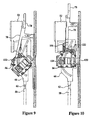
- Figure 9 is a side view of the portion of the rotary coring device in a second operational position within the wellbore
- Figure 10 is a side view of the portion of the rotary coring device in a third operational position within the wellbore
- Figure 11 is a side view of the variable reluctance position sensor utilized in the rotary coring device, in accordance with an exemplary embodiment
- Figure 12 is an isometric view of a rotor utilized in the variable reluctance position sensor of Figure 11 ;
- Figure 13 is a cross-sectional view of the variable reluctance position sensor of Figure 11 ;
- Figure 14 is a cross-sectional view of the variable reluctance position sensor of Figure 13 taken along lines 14-14;
- Figure 15 is a cross-sectional view of the variable reluctance position sensor of Figure 13 taken along lines 15-15;
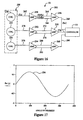
- Figure 16 is an electrical schematic of a position sensing system utilized in the core extraction system of Figure 1 .
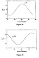
- Figures 17-19 are schematics of position signals generated by the variable reluctance position sensor of Figure 11 .
- a core extraction system 10 for obtaining a sidewall core from an earth formation 20 adjacent a wellbore is provided.
- the core extraction 10 includes a coring apparatus 12, a hoist 14, and a controller 16.
- the coring apparatus 12 is disposed at selected depths within the wellbore 18 of the earth formation 20 via a wireline 22 coupled to the hoist 14.
- the coring apparatus 12 is configured to acquire at least one sidewall core of a portion of the earth formation proximate the wellbore 18 at a predetermined depth.
- the coring apparatus 12 includes an electro-hydraulic section 30, a rotary coring device 32, and a core receptacle section 34.
- the electro-hydraulic section 30 is provided to house electrical components and circuits for controlling the extension and retraction of locking arms 40, 41 in response to control signals from the controller 16.
- the electro-hydraulic section 30 extends the locking arms 40, 41 in an outwardly direction to move the coring apparatus 12 adjacent a wall of the wellbore 18 for obtaining a sidewall core.
- the electro-hydraulic section 30 retracts the locking arms 40, 41 to move the coring apparatus 12 away from the wall.
- the electro-hydraulic section 30 further includes a hydraulic control system 40, which will be described in further detail below.
- the rotary coring device 32 is provided to acquire sidewall cores from the earth formation 20.
- the rotary coring device 32 includes an electrical motor 50, a transmission assembly 52, a position sensing system 54, a coring tool 56, hydraulic actuators 58, 60, shafts 62, 64, guide plates 66, 68, pivot arms 70, 72, hydraulic actuators 74, 76, connecting arms 78, 80, and a core ejecting shaft 82.
- the electrical motor 50 is provided to drive a gear assembly in the coring tool 56 for rotating a rotary coring bit 130 at one of a plurality of rotational speeds.
- the electrical motor 50 comprises a DC electrical motor.
- the electrical motor 50 can comprise any other motor known to those skilled in the art, such as a variable reluctance motor or a switched reluctance motor for example.
- the electrical motor 50 includes a stator (not shown) and a rotor 90 that rotates at one of a plurality of rotational speeds, in response to commutation signals from the controller 16.
- the controller 16 can generate commutation signals for inducing the electrical motor 50 to rotate at a first predetermined rotational speed in response to a predetermined parameter of the earth formation 20 at a first predetermined depth. Further for example, the controller 16 can generate commutation signals for inducing electrical motor 50 to rotate at a second predetermined rotational speed greater than the first predetermined speed, in response to a predetermined parameter of the earth formation 20 at a second predetermined depth.
- the electrical motor 50 is operably coupled to the transmission assembly 52.
- the rotor 90 of the motor 50 is operably coupled to a connecting member 100 of the transmission assembly 52.
- the transmission assembly 50 is provided to transfer torque from the motor 52 to a gear assembly in the coring tool 56.
- the transmission assembly 52 includes housing portions 96, 98, a coupling member 100, a drive shaft 102, a bevel gear 104, and a pinion gear 106.
- the housing portions 96, 98 are operably coupled together and define an interior region for enclosing the remaining components of the transmission assembly 52.
- the coupling member 100 is operably coupled at first end to the rotor 90 of the motor 50. Further, the coupling member 100 is operably coupled at a second end to a first end of the drive shaft 102. A second end of the drive shaft 102 is fixedly attached to the bevel gear 104.
- rotation of both the rotor 90 induces rotation of the drive shaft 102 and the bevel gear 104.
- the bevel gear 104 is operably coupled to the pinion gear 106.
- rotation of the bevel gear 100 induces rotation of the pinion gear 106.
- the coring tool 56 is provided for extracting a sidewall core from the earth formation 20.
- the coring tool 56 includes a housing 120, a gear assembly comprising a gear 122 and a gear 124, a movable plate 126, a pair of guide pins 128 (one being shown), a pair of guide pins 129 (one being shown), and a rotary coring bit 130.
- the housing 120 defines an interior region for holding the gear 122, the gear 124, and the movable plate 126.
- the movable plate 128 is movable along an axial direction of the rotary coring bit 130.
- the guide pins 128 are disposed on opposite sides of the movable plate 128 and are provided for the guiding movement of the rotary coring bit 130 in a linear direction (either outwardly or inwardly with respect to the housing 120) as will be explained in further detail below.
- the guide pins 129 are disposed on opposite sides of the housing 120 and are also provided for guiding movement of the rotary coring bit 130 in a linear direction (either outwardly or inwardly with respect to the housing 120) as will be explained in further detail below.
- the rotary coring device 32 includes hydraulic actuators 58, 60.
- the hydraulic actuators 58, 60 are provided to move the coring tool 56 to desired operational positions within the wellbore 18.
- the hydraulic actuators 58, 60 are configured to extend and retract piston shafts 62, 64, respectively.
- the shafts 62, 64 are further coupled to the guide plates 66, 68, respectively.
- the guide plates 66, 68 are provided to guide movement of the coring tool 56.
- the guide plate 66 includes cam slots 140, 142 extending therethrough.
- the cam slots 140, 142 are provided receive therein guide pins 128, 129 on a first side of the coring tool 56.
- the guide plate 68 includes cam slots 144, 146 extending therethrough.
- the cam slots 144, 146 are provided to receive therein guide pins 128, 129 on a second side of the coring tool 56.
- the pivot arms 70, 72 are operably coupled to the housing 120 of the coring tool 56.
- the pivot arm 70 has an elongated portion 160 and a U-shaped portion 162.
- the elongated portion 160 is connected at a first end to the housing 120.
- the elongated portion 160 is connected at a second end to the connecting arm 78.
- the U-shaped portion 162 extends outwardly from the elongated portion 160 and is configured to allow movement of the pivot arm 70 relative to a stationary pin.
- the pivot arm 72 has an elongated portion 164 and a U-shaped portion 166.
- the elongated portion 164 is connected at a first end to the housing 120.
- the elongated portion 164 is connected at a second end to the connecting arm 80.
- the U-shaped portion 166 extends outwardly from the elongated portion 164 and is configured to allow movement of the pivot arm 72 relative to a stationary pin.
- the hydraulic actuators 74, 76 are operably coupled to the connecting arms 78, 84 respectively, controlling movement of the coring tool 56. In particular, hydraulic actuators 74, 76 retract or extend the connecting arms 78, 80, respectively, to move the coring tool 56.
- the core injecting shaft 82 is utilized to contact a sidewall core contained within the coring tool 56 for ejecting the core from the coring tool 56 into the core receptacle section 34 when the coring tool 56 is disposed in an upright position in the wellbore 18 as shown in Figure 8 .
- the coring tool 56 is disposed beneath the transmission assembly 52 in the wellbore 18.
- the controller 16 outputs command signals to the hydraulic control system 40.
- the command signals induce the hydraulic control system 42 to induce the hydraulic actuators 58, 60 to urge the guide plates 66, 68, respectively, upwardly which causes the rotary coring tool 56 to rotate such that the rotary coring bit 130 is moved outwardly from the housing 120 of the coring tool 56.
- the guide pins 128, 129 on a first side of the rotary coring tool 56 move within the cam slots 140, 142.
- the guide pins 128, 129 on a second side of the rotary coring tool 56 move within the cam slots 144, 146 on the guide plate 68.
- the gear 106 of the transmission assembly 52 is operably coupled to the gear 122 of the coring tool 56, for transmitting torque to the gear 122.
- the guide pins 128 attached to the movable plate 126 urge the movable plate 126 outwardly (rightwardly in Figure 10 ) such that the rotary coring bit 130 contacts a portion of the earth formation 20.
- the controller 16 generates commutation signals to induce the motor 50 to rotate the rotary coring bit 130 for acquiring a sidewall core.
- the position sensing system 54 is provided to generate position signals indicative of a rotational position of the rotor 90 of the motor 50.
- the signals generated by the position sensing system 54 are received by the controller 16 and the controller 16 generates commutation signals for controlling operation of the motor 50, in response to the position signals.
- the position sensing system 54 includes the variable reluctance position sensor 180 and the amplifier circuit 182.
- variable reluctance position sensor 180 is configured to be mechanically coupled to the rotor 90 of the motor 50 for generating voltage signals indicative of a position of the rotor 90.
- An advantage of the variable reluctance position sensor 180 is that the sensor is not electrically coupled to the motor 50, thus eliminating electrical noise generated by the motor 50, from position signals generated by the sensor 180.
- a further advantage of the variable reluctance position sensor 180 is that the sensor 180 can generate accurate position signals when operating at relatively high temperatures.
- the variable reluctance position sensor 180 includes a housing 190, a rotor 192, magnets 194, 196, 198, 200, 202, 204, 206, 208, and a stator assembly 210.
- the housing 190 is provided to enclose the remaining components of the variable reluctance position sensor 180.
- the housing 190 is constructed from a non-magnetic material, such as aluminum for example.
- the rotor 192 is positioned within an aperture defined by the stator assembly 210.
- the rotor 192 is generally cylindrical-shaped and is constructed from a non-magnetic material, such as plastic for example.
- the rotor 192 includes a first plurality of apertures extending from an outer surface of the rotor 192 inwardly into the rotor 192, for receiving magnets 194, 196, 198, and 200 therein.
- the magnets 194, 196, 198, and 200 are disposed at positions 90° apart from one another about an axis 201, at a first predetermined axial position along the rotor 192.
- the rotor 192 includes a second plurality of apertures extending from the outer surface of the rotor 192 inwardly into the rotor 192, for receiving magnets 202, 204, 206, 208 therein.
- the magnets 202, 204, 206, 208 are disposed at positions 90° apart from one another about the axis 201, at a second predetermined axial position along the rotor 192.
- the magnets 202, 204, 206, 208 are offset 45 degrees from magnets 194, 196, 198, and 200 about the axis 201.
- the rotor 192 further includes an aperture 193 extending from a first end of the rotor 192 inwardly into the rotor 192 a predetermined distance.
- the aperture 193 is configured to receive an end of the rotor 90 of the motor 50 for fixedly coupling the rotor 192 to the rotor 90.
- the rotor 192 rotates at a substantially similar speed as the rotor 90 of the motor 50.
- the stator assembly 210 includes a non-magnetic body portion 212, coil brackets 214, 216, 218 and coils 230, 232, 234.
- the non-magnetic body portion 212 is generally ring-shaped and has an aperture extending therethrough with a diameter larger than an outer diameter of the rotor 192. In other words, a small air gap is defined between an outer surface of the rotor 192 and inner surface defined by the non-magnetic body portion 212.
- the coil brackets 214, 216, 218 are provided to fixedly hold the coils 230, 232, 234, respectively thereon.
- the coil brackets 214, 216, 218 are configured to be disposed in apertures extending into an exterior surface of the non-magnetic body portion 212.
- the coil brackets 214, 216, 218 are disposed at positions 120° apart from one another about the axis 201. Further, the coil brackets 214, 216, 218 are constructed from carbon steel for concentrating magnetic flux from the rotor magnets around the coils 230, 232, 234, respectively.
- the operation of the variable reluctance position sensor 180 will now be explained.
- the sensor 180 utilizes an interaction between electromagnetic fields generated by the magnets on the rotor 192 and electrical currents generated in the coils 230, 232, 234 in response to the electromagnetic fields moving past the coils 230, 232, 234 when the rotor 192 is rotating.
- Faraday's Law of electromagnetic induction states that a voltage (i.e., an electro-magnetic force EMF) is induced in a conductor such as a coil, when magnetic flux lines are at a right angle with respect to the conductor.
- an exemplary voltage waveform 236 representing the voltage (Ea) generated by the coil 230 over time is illustrated.
- an exemplary voltage waveform 238 representing the voltage (Eb) generated by the coil 232 over time is illustrated.
- an exemplary voltage waveform 240 representing the voltage (Ec) generated by the coil 234 over time is illustrated.
- the amplifier circuit 182 for amplifying and filtering out noise in the voltages (Ea), (Eb), and (Ec) is illustrated.
- the amplifier circuit 182 includes differential amplifiers 250, 252, 254, noise cancellation amplifiers 256, 258, 260, and conductors 262, 264, 266, 268, 270, 272, 274, 276, 278, 280, 282, and 284.
- the coil 230 is electrically coupled to an input terminal of the amplifier 250 via the conductor 262.
- the amplifier 250 has first and second output terminals electrically coupled to first and second terminals of the amplifier 256 via the conductors 264, 266, respectively.
- An output terminal of the amplifier 256 is electrically coupled to the controller 16 via the conductor 268.
- the amplifier 250 receives the voltage (Ea) from the coil 230 and outputs an amplified voltage (G*Ea) on the conductor 264 and an amplified voltage (-G*Ea) on the conductor 266, where G corresponds to a predetermined voltage gain.
- the noise cancellation amplifier 256 outputs the voltage (Ea'), having less electrical noise than voltage (Ea), in response to receiving the voltages (G*Ea) and (-G*Ea).
- the voltage (Ea') which is indicative of the position of the rotor 90 is received by the controller 16.
- the coil 232 is electrically coupled to an input terminal of the amplifier 252 via the conductor 270.
- the amplifier 252 has first and second output terminals electrically coupled to first and second terminals of the amplifier 258 via the conductors 272, 274, respectively.
- An output terminal of the amplifier 258 is electrically coupled to the controller 16 via the conductor 276.
- the amplifier 252 receives the voltage (Eb) from the coil 232 and outputs an amplified voltage (G*Eb) on the conductor 272 and an amplified voltage (-G*Eb) on the conductor 274, where G corresponds to the predetermined voltage gain.
- the noise cancellation amplifier 258 outputs the voltage (Eb'), having less electrical noise than voltage (Eb), in response to receiving the voltages (G*Eb) and (-G*Eb).
- the voltage (Eb') which is also indicative of the position of the rotor 90 is received by the controller 16.
- the coil 234 is electrically coupled to an input terminal of the amplifier 254 via the conductor 278.
- the amplifier 254 has first and second output terminals electrically coupled to first and second terminals of the amplifier 260 via the conductors 280, 282, respectively.
- An output terminal of the amplifier 260 is electrically coupled to the controller 16 via the conductor 284.
- the amplifier 254 receives the voltage (Ec) from the coil 234 and outputs an amplified voltage (G*Ec) on the conductor 280 and an amplified voltage (-G*Ec) on the conductor 282, where G corresponds to the predetermined voltage gain.
- the noise cancellation amplifier 260 outputs the voltage (Ec'), having less electrical noise than voltage (Ec), in response to receiving the voltages (G*Ec) and (-G*Ec).
- the voltage (Ec') which is indicative of the position of the rotor 90 is received by the controller 16.
- the controller 16 is provided to control operation of the coring apparatus 12 and the hoist 14.
- the controller 16 generates control signals for controlling operation of the hoist 14 for positioning the rotary coring device 32 at predetermined depths within the wellbore 18.
- the controller 16 generates control signals for controlling operation of the hydraulic control system 44 for orientating the coring tool 56 of the rotary coring device 32 within the wellbore 20 for acquiring a sidewall core.
- the controller 16 generates control signals for controlling operation of the motor 50 utilized in the rotary coring device 32 for driving the rotary coring bit 130.
- the controller 16 receives the position voltages (Ea') (Eb'), (Ec') from the position sensing system 54 and utilizes the position voltages for controlling operation of the motor 50.
- the rotary coring device and the method for acquiring a sidewall core provide a substantial advantage over other devices and methods.
- the rotary coring device provides a technical effect of utilizing an electric motor to drive a rotary coring bit which operates effectively at relatively high temperatures, (e.g. greater than 350°F (176.6°C) while utilizing a hydraulic actuator to orientate the coring tool within a wellbore which reduces the amount of electrical power needed to obtain the sidewall core.
- the above-described methods can be embodied in the form of computer-implemented processes and apparatuses for practicing those processes.
- the method is embodied in computer program code executed by the computer or controller.
- the method may be embodied in the form of computer program code containing instructions embodied in tangible media, such as floppy diskettes, CD-ROMs, hard drives, or any other computer-readable storage medium, wherein, when the computer program code is loaded into and executed by a controller, the controller becomes an apparatus for practicing the invention.
Landscapes
- Life Sciences & Earth Sciences (AREA)
- Geology (AREA)
- Mining & Mineral Resources (AREA)
- Engineering & Computer Science (AREA)
- General Life Sciences & Earth Sciences (AREA)
- Fluid Mechanics (AREA)
- Soil Sciences (AREA)
- Environmental & Geological Engineering (AREA)
- Physics & Mathematics (AREA)
- Geochemistry & Mineralogy (AREA)
- Earth Drilling (AREA)
- Excavating Of Shafts Or Tunnels (AREA)
- Geophysics And Detection Of Objects (AREA)
- Sampling And Sample Adjustment (AREA)
- Investigation Of Foundation Soil And Reinforcement Of Foundation Soil By Compacting Or Drainage (AREA)
Claims (13)
- Rotierende Kernbohrvorrichtung zum Schneiden einer Erdformation neben einem Bohrloch, umfassend:ein Werkzeug (56), das ein erstes Getriebe (122, 124) hat, welches betreibbar mit einer rotierenden Kernbohrkrone (130) verbunden ist, wobei das erste Getriebe zum Drehen der Bohrerspitze ausgelegt ist;einen Elektromotor (50), der zum Antreiben des ersten Getriebes (122, 124) zum Drehen der Bohrerspitze (130) ausgelegt ist;einen hydraulischen Aktor (58, 60, 74, 76), der zum Bewegen der Bohrerspitze in einer ersten Richtung weg vom Werkzeug in Richtung auf die Erdformation (20) ausgelegt ist;dadurch gekennzeichnet, dass die rotierende Kernbohrvorrichtung ferner einen Positionssensor (180) mit variablem magnetischem widerstand umfasst, der betreibbar mit einem Rotor (90) des Elektromotors (50) verbunden ist, wobei der Positionssensor (180) Signale erzeugt, die eine Rotationsposition des Rotors (90) anzeigen; undeinen Controller (16, 40), der elektrisch mit dem Elektromotor (50) verbunden ist, wobei der Controller zum Empfangen der Positionssignale und zum Erzeugen von Kommutierungssignalen ausgelegt ist, um den Elektromotor (50) zu veranlassen, die Bohrerspitze (130) mit einer aus mehreren Rotationsgeschwindigkeiten zu drehen, einschließlich einer ersten Rotationsgeschwindigkeit, die auf einem ersten Parameter beruht, welcher mit einem Teil der Erdformation (20) verbunden ist, oder mit einer zweiten Rotationsgeschwindigkeit, die auf einem zweiten Parameter beruht, welcher mit einem Teil der Erdformation (20) verbunden ist.
- Rotierende Schneidvorrichtung nach Anspruch 1, wobei der Elektromotor (50) einen Gleichspannungs-Elektromotor umfasst.
- Rotierende Schneidvorrichtung nach Anspruch 1 oder 2, die ferner eine Antriebswelleneinheit (52) umfasst, welche betreibbar zwischen den Elektromotor (50) und das erste Getriebe (122, 124) gelegt ist, wobei die erste Antriebswelleneinheit eine Antriebswelle (100, 102) und ein zweites Getriebe (104, 106) umfasst, wobei die Antriebswelle an einem ersten Ende mit einem Rotor (90) des Elektromotors (50) verbunden ist, wobei die Antriebswelle an einem zweiten Ende mit dem zweiten Getriebe (104, 106) verbunden ist, wobei das zweite Getriebe betreibbar mit dem ersten Getriebe (122, 124) verbunden ist.
- Rotierende Schneidvorrichtung nach einem der vorherigen Ansprüche, wobei der hydraulische Aktor (58, 60, 74, 76) ferner zum Bewegen der Bohrerspitze (130) in einer zweiten Richtung entgegengesetzt zur ersten Richtung ausgelegt ist.
- Rotierende Schneidvorrichtung nach einem der vorherigen Ansprüche, wobei die Bohrerspitze (130) ferner dafür ausgelegt ist, einen Seitenwandkern aus der Erdformation (20) zu erhalten.
- Rotierende Schneidvorrichtung nach einem der vorherigen Ansprüche, wobei der hydraulische Aktor (58, 60, 74, 76) ferner zum Drehen des werkzeugs (56) in einem winkelbereich von 0-90 Grad ausgelegt ist.
- Rotierende Schneidvorrichtung nach Anspruch 6, wobei in der 0-Grad-Position die Bohrerspitze (130) sich in einer Richtung im wesentlichen parallel zur Erdformation (20) und in der 90-Grad-Position sich die Bohrerspitze (130) in einer anderen Richtung erstreckt, die im wesentlichen senkrecht zur Erdformation (20) ist.
- Verfahren zum Gewinnen von mindestens einem Seitenwandkern aus einer Erdformation neben einem Bohrloch, umfassend:Rotieren einer rotierenden Kernbohrkrone (130), die ein erstes Getriebe (122, 124) nutzt, welches von einem Elektromotor (50) angetrieben wird;Bewegen der rotierenden Bohrerspitze (130) in einer ersten Richtung zur Erdformation (20), wobei ein hydraulischer Aktor (58, 60, 74, 76) verwendet wird, um den Seitenwandkern zu erhalten;dadurch gekennzeichnet, dass das Verfahren ferner das Erzeugen von Positionssignalen, die eine Rotationsposition eines Rotors (90) anzeigen, unter Verwendung eines Positionssensors (180) mit variablem magnetischem Widerstand umfasst, der betreibbar mit dem Rotor (90) verbunden ist; undErzeugen von Kommutierungssignalen unter Verwendung eines Controllers (16, 40), der die Positionssignale empfängt, um den Elektromotor zu veranlassen, die Bohrerspitze mit einer von mehreren Rotationsgeschwindigkeiten einschließlich einer ersten Rotationsgeschwindigkeit zu drehen, die auf einem ersten Parameter beruht, welcher mit einem Teil der Erdformation verbunden ist, oder mit einer zweiten Rotationsgeschwindigkeit, die auf einem zweiten Parameter beruht, welcher mit einem Teil der Erdformation verbunden ist.
- Verfahren nach Anspruch 8, das ferner das Bewegen der Bohrerspitze (130) in einer zweiten Richtung weg von der Erdformation (20) umfasst, wobei der hydraulische Aktor (58, 60, 74, 76) verwendet wird.
- Verfahren nach Anspruch 9, wobei die zweite Richtung der ersten Richtung entgegengesetzt ist.
- Verfahren nach Anspruch 8, 9 oder 10, das ferner das Gewinnen eines Seitenwandkerns aus der Erdformation (20) unter Verwendung der Bohrerspitze (130) umfasst.
- Verfahren nach einem der Ansprüche 8 bis 11, das ferner das Drehen des Werkzeugs (56) in einem winkelbereich von 0-90 Grad umfasst.
- Verfahren nach Anspruch 12, wobei in der 0-Grad-Position die Bohrerspitze (130) sich in einer Richtung im Wesentlichen parallel zur Erdformation (20) erstreckt und in der 90-Grad-Position sich die Bohrerspitze (130) in einer anderen Richtung erstreckt, die im Wesentlichen senkrecht zur Erdformation (20) ist.
Applications Claiming Priority (2)
| Application Number | Priority Date | Filing Date | Title |
|---|---|---|---|
| US11/215,271 US7530407B2 (en) | 2005-08-30 | 2005-08-30 | Rotary coring device and method for acquiring a sidewall core from an earth formation |
| PCT/US2006/033697 WO2007027683A2 (en) | 2005-08-30 | 2006-08-28 | Rotary coring device and method for acquiring a sidewall core from an earth formation |
Publications (3)
| Publication Number | Publication Date |
|---|---|
| EP1920136A2 EP1920136A2 (de) | 2008-05-14 |
| EP1920136A4 EP1920136A4 (de) | 2011-05-11 |
| EP1920136B1 true EP1920136B1 (de) | 2013-04-10 |
Family
ID=37802457
Family Applications (1)
| Application Number | Title | Priority Date | Filing Date |
|---|---|---|---|
| EP06813910.4A Not-in-force EP1920136B1 (de) | 2005-08-30 | 2006-08-28 | Drehspulenvorrichtung und verfahren zum erhalt einer seitenwandspule aus einer erdformation |
Country Status (6)
| Country | Link |
|---|---|
| US (1) | US7530407B2 (de) |
| EP (1) | EP1920136B1 (de) |
| CN (1) | CN101253309B (de) |
| CA (1) | CA2619976C (de) |
| EA (1) | EA011911B1 (de) |
| WO (1) | WO2007027683A2 (de) |
Families Citing this family (30)
| Publication number | Priority date | Publication date | Assignee | Title |
|---|---|---|---|---|
| GB2448928B (en) * | 2007-05-04 | 2009-12-09 | Dynamic Dinosaurs Bv | Power transmission system for use with downhole equipment |
| US8550184B2 (en) * | 2007-11-02 | 2013-10-08 | Schlumberger Technology Corporation | Formation coring apparatus and methods |
| US8061446B2 (en) | 2007-11-02 | 2011-11-22 | Schlumberger Technology Corporation | Coring tool and method |
| US7841402B2 (en) * | 2008-04-09 | 2010-11-30 | Baker Hughes Incorporated | Methods and apparatus for collecting a downhole sample |
| US7836951B2 (en) * | 2008-04-09 | 2010-11-23 | Baker Hughes Incorporated | Methods and apparatus for collecting a downhole sample |
| GB2478455B (en) * | 2008-10-31 | 2013-04-10 | Schlumberger Holdings | An integrated coring system |
| WO2011044427A2 (en) * | 2009-10-09 | 2011-04-14 | Schlumberger Canada Limited | Automated sidewall coring |
| DE102010013724B4 (de) * | 2010-03-31 | 2015-09-24 | Gdf Suez | Horizontalbohrvorrichtung |
| US8919460B2 (en) * | 2011-09-16 | 2014-12-30 | Schlumberger Technology Corporation | Large core sidewall coring |
| US9447681B2 (en) * | 2011-09-26 | 2016-09-20 | Saudi Arabian Oil Company | Apparatus, program product, and methods of evaluating rock properties while drilling using downhole acoustic sensors and a downhole broadband transmitting system |
| US10551516B2 (en) | 2011-09-26 | 2020-02-04 | Saudi Arabian Oil Company | Apparatus and methods of evaluating rock properties while drilling using acoustic sensors installed in the drilling fluid circulation system of a drilling rig |
| CN102619484B (zh) * | 2012-04-11 | 2014-09-10 | 中国石油集团川庆钻探工程有限公司钻采工程技术研究院 | 随钻井壁取心工具 |
| US9359891B2 (en) | 2012-11-14 | 2016-06-07 | Baker Hughes Incorporated | LWD in-situ sidewall rotary coring and analysis tool |
| US20140166366A1 (en) | 2012-12-13 | 2014-06-19 | Smith International, Inc. | Single-trip lateral coring systems and methods |
| DK3502411T3 (en) * | 2014-08-21 | 2021-05-03 | Agat Tech As | Anchoring module for well tools |
| US10472912B2 (en) | 2014-08-25 | 2019-11-12 | Schlumberger Technology Corporation | Systems and methods for core recovery |
| CN104373120B (zh) * | 2014-11-28 | 2017-01-25 | 中国石油天然气集团公司 | 一种测井钻进式井壁取心器的控制系统及控制方法 |
| US10047580B2 (en) | 2015-03-20 | 2018-08-14 | Baker Hughes, A Ge Company, Llc | Transverse sidewall coring |
| GB2562649A (en) * | 2015-12-09 | 2018-11-21 | Tyrfing Innovation As | A downhole tubular verification and centralizing device, and method |
| CN105672924B (zh) * | 2016-01-21 | 2019-09-13 | 中国海洋石油集团有限公司 | 一种电动机直驱式井壁取芯结构 |
| CN106223885B (zh) * | 2016-07-21 | 2018-09-11 | 中国海洋石油集团有限公司 | 电动减速机导线随动保护结构 |
| CN106246124A (zh) * | 2016-07-29 | 2016-12-21 | 中国石油天然气股份有限公司 | 井下检测系统及其方法 |
| US20180058210A1 (en) * | 2016-08-23 | 2018-03-01 | Baker Hughes Incorporated | Downhole robotic arm |
| CN106285663B (zh) * | 2016-09-13 | 2022-04-12 | 中国石油天然气集团有限公司 | 投捞式井底取样工具 |
| RU2652216C1 (ru) * | 2017-03-14 | 2018-04-25 | федеральное государственное бюджетное образовательное учреждение высшего образования "Уфимский государственный авиационный технический университет" | Боковой сверлящий электрогидравлический керноотборник |
| CN108868676B (zh) * | 2018-05-31 | 2020-08-25 | 中国石油集团长城钻探工程有限公司 | 一种过套管穿透井壁取芯工具 |
| CN108756874B (zh) * | 2018-06-11 | 2021-09-10 | 中国海洋石油集团有限公司 | 一种测井仪器及取心取样方法 |
| CN111157701B (zh) | 2020-01-03 | 2021-12-10 | 中国海洋石油集团有限公司 | 一种取心取样一体化测井仪器 |
| CA3144649A1 (en) | 2020-12-31 | 2022-06-30 | Rus-Tec Engineering, Ltd. | System and method of obtaining formation samples using coiled tubing |
| NO20240442A1 (en) * | 2024-05-07 | 2025-11-10 | Altus Intervention Tech As | A method and a system for drilling a radial hole in a tubular structure |
Family Cites Families (34)
| Publication number | Priority date | Publication date | Assignee | Title |
|---|---|---|---|---|
| US2181512A (en) * | 1937-01-18 | 1939-11-28 | John H Kirby | Sample taking device |
| US2181980A (en) * | 1938-09-16 | 1939-12-05 | Roy Q Seale | Device for obtaining core samples |
| US2516421A (en) * | 1945-08-06 | 1950-07-25 | Jerry B Robertson | Drilling tool |
| US3677080A (en) * | 1971-06-16 | 1972-07-18 | Gearhart Owen Industries | Sidewall well-formation fluid sampler |
| US4354558A (en) * | 1979-06-25 | 1982-10-19 | Standard Oil Company (Indiana) | Apparatus and method for drilling into the sidewall of a drill hole |
| US4280569A (en) * | 1979-06-25 | 1981-07-28 | Standard Oil Company (Indiana) | Fluid flow restrictor valve for a drill hole coring tool |
| US4396074A (en) * | 1981-11-16 | 1983-08-02 | Standard Oil Company (Indiana) | Drill bit extension for sidewall corer |
| NO842127L (no) * | 1983-06-01 | 1984-12-03 | Trelleborg Ab | Anordning ved haandtak for vibrerende maskiner |
| US4702168A (en) * | 1983-12-01 | 1987-10-27 | Halliburton Company | Sidewall core gun |
| US4714119A (en) * | 1985-10-25 | 1987-12-22 | Schlumberger Technology Corporation | Apparatus for hard rock sidewall coring a borehole |
| US4679636A (en) * | 1986-10-16 | 1987-07-14 | Ruhle James L | Method and apparatus for coring rock |
| US4914591A (en) * | 1988-03-25 | 1990-04-03 | Amoco Corporation | Method of determining rock compressive strength |
| US5012674A (en) * | 1988-10-31 | 1991-05-07 | Amoco Corporation | Method of exploration for hydrocarbons |
| US5183111A (en) * | 1991-08-20 | 1993-02-02 | Schellstede Herman J | Extended reach penetrating tool and method of forming a radial hole in a well casing |
| US5310013A (en) * | 1992-08-24 | 1994-05-10 | Schlumberger Technology Corporation | Core marking system for a sidewall coring tool |
| WO1994010421A1 (en) * | 1992-10-30 | 1994-05-11 | Western Atlas International, Inc. | Sidewall rotary coring tool |
| US5411106A (en) * | 1993-10-29 | 1995-05-02 | Western Atlas International, Inc. | Method and apparatus for acquiring and identifying multiple sidewall core samples |
| US5439065A (en) * | 1994-09-28 | 1995-08-08 | Western Atlas International, Inc. | Rotary sidewall sponge coring apparatus |
| US5487433A (en) * | 1995-01-17 | 1996-01-30 | Westers Atlas International Inc. | Core separator assembly |
| US6230822B1 (en) * | 1995-02-16 | 2001-05-15 | Baker Hughes Incorporated | Method and apparatus for monitoring and recording of the operating condition of a downhole drill bit during drilling operations |
| US5667025A (en) * | 1995-09-29 | 1997-09-16 | Schlumberger Technology Corporation | Articulated bit-selector coring tool |
| US6186248B1 (en) * | 1995-12-12 | 2001-02-13 | Boart Longyear Company | Closed loop control system for diamond core drilling |
| US6107772A (en) * | 1997-09-26 | 2000-08-22 | Dana Corporation | Sensorless switched reluctance motor control |
| US6367565B1 (en) * | 1998-03-27 | 2002-04-09 | David R. Hall | Means for detecting subterranean formations and monitoring the operation of a down-hole fluid driven percussive piston |
| GB9810321D0 (en) * | 1998-05-15 | 1998-07-15 | Head Philip | Method of downhole drilling and apparatus therefore |
| WO2001061141A1 (en) * | 2000-02-16 | 2001-08-23 | Performance Research & Drilling, Llc | Horizontal directional drilling in wells |
| NO312255B1 (no) * | 2000-06-28 | 2002-04-15 | Pgs Reservoir Consultants As | Verktöy for gjennomhulling av et langsgående veggparti av et fôringsrör |
| US6371221B1 (en) * | 2000-09-25 | 2002-04-16 | Schlumberger Technology Corporation | Coring bit motor and method for obtaining a material core sample |
| US6729416B2 (en) * | 2001-04-11 | 2004-05-04 | Schlumberger Technology Corporation | Method and apparatus for retaining a core sample within a coring tool |
| US6672407B2 (en) * | 2001-09-20 | 2004-01-06 | Halliburton Energy Services, Inc. | Method of drilling, analyzing and stabilizing a terrestrial or other planetary subsurface formation |
| US7188674B2 (en) * | 2002-09-05 | 2007-03-13 | Weatherford/Lamb, Inc. | Downhole milling machine and method of use |
| US20050133267A1 (en) | 2003-12-18 | 2005-06-23 | Schlumberger Technology Corporation | [coring tool with retention device] |
| US7191831B2 (en) * | 2004-06-29 | 2007-03-20 | Schlumberger Technology Corporation | Downhole formation testing tool |
| US7404456B2 (en) * | 2004-10-07 | 2008-07-29 | Halliburton Energy Services, Inc. | Apparatus and method of identifying rock properties while drilling |
-
2005
- 2005-08-30 US US11/215,271 patent/US7530407B2/en not_active Expired - Fee Related
-
2006
- 2006-08-28 CA CA2619976A patent/CA2619976C/en not_active Expired - Fee Related
- 2006-08-28 WO PCT/US2006/033697 patent/WO2007027683A2/en not_active Ceased
- 2006-08-28 EA EA200800623A patent/EA011911B1/ru not_active IP Right Cessation
- 2006-08-28 CN CN2006800316262A patent/CN101253309B/zh not_active Expired - Fee Related
- 2006-08-28 EP EP06813910.4A patent/EP1920136B1/de not_active Not-in-force
Also Published As
| Publication number | Publication date |
|---|---|
| EA011911B1 (ru) | 2009-06-30 |
| EP1920136A4 (de) | 2011-05-11 |
| US7530407B2 (en) | 2009-05-12 |
| US20070045005A1 (en) | 2007-03-01 |
| CN101253309B (zh) | 2012-06-27 |
| EA200800623A1 (ru) | 2008-12-30 |
| CN101253309A (zh) | 2008-08-27 |
| CA2619976A1 (en) | 2007-03-08 |
| CA2619976C (en) | 2012-04-17 |
| WO2007027683A3 (en) | 2007-09-20 |
| EP1920136A2 (de) | 2008-05-14 |
| WO2007027683A2 (en) | 2007-03-08 |
Similar Documents
| Publication | Publication Date | Title |
|---|---|---|
| CA2619976C (en) | Rotary coring device and method for acquiring a sidewall core from an earth formation | |
| US7411388B2 (en) | Rotary position sensor and method for determining a position of a rotating body | |
| EP1792052B1 (de) | Integriertes magnetisches vermessungswerkzeug | |
| CN105556053A (zh) | 可浸没电机及方法 | |
| US9447641B2 (en) | Rotary steerable drilling tool with a linear motor | |
| US20120062160A1 (en) | Permanent Magnet Motor with Stator-Based Saliency for Position Sensorless Drive | |
| US7755235B2 (en) | Downhole generator for drillstring instruments | |
| JPH0224970B2 (de) | ||
| EP3364531A1 (de) | Hybridmotor und zugehöriges verfahren davon | |
| EP3575546B1 (de) | Linearantriebssystem für bohrlochanwendungen | |
| CN109510422B (zh) | 一种电磁驱动电机及旋转导向钻井工具 | |
| US9580968B2 (en) | Rotary steerable drilling tool with electromagnetic steering system | |
| CA2746081C (en) | Contactless position detection switch | |
| CN111555474B (zh) | 直线旋转钻进电机 | |
| CN209016908U (zh) | 一种用于高液压浸油直流无刷电机 | |
| CN106248996A (zh) | 一种交流伺服测角加速度机组 | |
| Sun et al. | Research on torque of based hydraulic rotary hole cleaning tool on Halbach permanent magnet array | |
| CN119051314A (zh) | 容屑型通量引导式井下旋转机器 | |
| CN106290980A (zh) | 一种永磁式直流伺服测角加速度机组 | |
| CN106153973A (zh) | 一种新型一体式交流伺服测速机组 | |
| KR19980055448U (ko) | 전동식 동력 조향장치 | |
| BRPI1105600A2 (pt) | aparelho de ressonância magnética nuclear, e método para perfilar uma formação |
Legal Events
| Date | Code | Title | Description |
|---|---|---|---|
| PUAI | Public reference made under article 153(3) epc to a published international application that has entered the european phase |
Free format text: ORIGINAL CODE: 0009012 |
|
| 17P | Request for examination filed |
Effective date: 20080222 |
|
| AK | Designated contracting states |
Kind code of ref document: A2 Designated state(s): FR GB |
|
| DAX | Request for extension of the european patent (deleted) | ||
| RBV | Designated contracting states (corrected) |
Designated state(s): FR GB |
|
| RAP1 | Party data changed (applicant data changed or rights of an application transferred) |
Owner name: BAKER HUGHES INCORPORATED |
|
| A4 | Supplementary search report drawn up and despatched |
Effective date: 20110127 |
|
| RIC1 | Information provided on ipc code assigned before grant |
Ipc: E21B 49/06 20060101AFI20110121BHEP |
|
| RA4 | Supplementary search report drawn up and despatched (corrected) |
Effective date: 20110408 |
|
| GRAP | Despatch of communication of intention to grant a patent |
Free format text: ORIGINAL CODE: EPIDOSNIGR1 |
|
| GRAS | Grant fee paid |
Free format text: ORIGINAL CODE: EPIDOSNIGR3 |
|
| GRAA | (expected) grant |
Free format text: ORIGINAL CODE: 0009210 |
|
| AK | Designated contracting states |
Kind code of ref document: B1 Designated state(s): FR GB |
|
| REG | Reference to a national code |
Ref country code: GB Ref legal event code: FG4D |
|
| PLBE | No opposition filed within time limit |
Free format text: ORIGINAL CODE: 0009261 |
|
| STAA | Information on the status of an ep patent application or granted ep patent |
Free format text: STATUS: NO OPPOSITION FILED WITHIN TIME LIMIT |
|
| 26N | No opposition filed |
Effective date: 20140113 |
|
| REG | Reference to a national code |
Ref country code: FR Ref legal event code: ST Effective date: 20140430 |
|
| PG25 | Lapsed in a contracting state [announced via postgrant information from national office to epo] |
Ref country code: FR Free format text: LAPSE BECAUSE OF NON-PAYMENT OF DUE FEES Effective date: 20130902 |
|
| PGFP | Annual fee paid to national office [announced via postgrant information from national office to epo] |
Ref country code: GB Payment date: 20150826 Year of fee payment: 10 |
|
| GBPC | Gb: european patent ceased through non-payment of renewal fee |
Effective date: 20160828 |
|
| PG25 | Lapsed in a contracting state [announced via postgrant information from national office to epo] |
Ref country code: GB Free format text: LAPSE BECAUSE OF NON-PAYMENT OF DUE FEES Effective date: 20160828 |