EP1919634B1 - Assembly for removing impurities in crushed recycled material - Google Patents
Assembly for removing impurities in crushed recycled material Download PDFInfo
- Publication number
- EP1919634B1 EP1919634B1 EP06752672A EP06752672A EP1919634B1 EP 1919634 B1 EP1919634 B1 EP 1919634B1 EP 06752672 A EP06752672 A EP 06752672A EP 06752672 A EP06752672 A EP 06752672A EP 1919634 B1 EP1919634 B1 EP 1919634B1
- Authority
- EP
- European Patent Office
- Prior art keywords
- outlet
- chute
- air
- impurities
- screen
- Prior art date
- Legal status (The legal status is an assumption and is not a legal conclusion. Google has not performed a legal analysis and makes no representation as to the accuracy of the status listed.)
- Active
Links
Images


Classifications
-
- B—PERFORMING OPERATIONS; TRANSPORTING
- B07—SEPARATING SOLIDS FROM SOLIDS; SORTING
- B07B—SEPARATING SOLIDS FROM SOLIDS BY SIEVING, SCREENING, SIFTING OR BY USING GAS CURRENTS; SEPARATING BY OTHER DRY METHODS APPLICABLE TO BULK MATERIAL, e.g. LOOSE ARTICLES FIT TO BE HANDLED LIKE BULK MATERIAL
- B07B4/00—Separating solids from solids by subjecting their mixture to gas currents
- B07B4/08—Separating solids from solids by subjecting their mixture to gas currents while the mixtures are supported by sieves, screens, or like mechanical elements
-
- B—PERFORMING OPERATIONS; TRANSPORTING
- B07—SEPARATING SOLIDS FROM SOLIDS; SORTING
- B07B—SEPARATING SOLIDS FROM SOLIDS BY SIEVING, SCREENING, SIFTING OR BY USING GAS CURRENTS; SEPARATING BY OTHER DRY METHODS APPLICABLE TO BULK MATERIAL, e.g. LOOSE ARTICLES FIT TO BE HANDLED LIKE BULK MATERIAL
- B07B9/00—Combinations of apparatus for screening or sifting or for separating solids from solids using gas currents; General arrangement of plant, e.g. flow sheets
Definitions
- the present invention relates to an apparatus and method for removing impurities in crushed material such as concrete to be recycled.
- recycled 80 mm minus, 20 mm minus and dust concrete can be used again in the building of new buildings or other purposes.
- the crushed concrete however is contaminated with large amounts of foreign material such as timber, plastics, light aluminium, wire, asbestos, and other material.
- document US 3,909,873 discloses a coke dedusting device comprising an inclined trough along which particles of coke travel downwards by gravity.
- the trough has transverse slots providing a grate, with compressed air passing across the trough to blow the dust towards an outlet opposite the grate.
- Document US 2,203,821 discloses a device for expanding or exfoliating fragments of vermiculite and for separating the stones and dust therefrom.
- the device comprises an inclined chute along which exfoliated vermiculite slides downwardly.
- the chute comprises an opening from which an upward blast of air elevates the vermiculite fragments and makes them fall downwardly beyond the opening, conversely the stones are not elevated and fall into the opening and the dust is sufficiently elevated so as to be propelled in a chamber opposite the opening.
- Document US 4,631,124 discloses a device for removing dust from a stream of material passing through the device.
- the dust laden material enters a first cleaning chamber comprising a perforated inclined base plate along which the material slides, and a blower mounted below the base plate so as to direct an air flow through the perforations and blow the dust toward an exhaust port.
- the material cleaned of most of the dust is directed to a second cleaning chamber similar to the first chamber for removal of the remaining dust.
- a processing apparatus to remove impurities from crushed material that is to be recycled including:
- said chute is inclined to the horizontal by the acute angle so that said first side is above the opposite side.
- said chute has a transverse width, with said air outlet extending across said width.
- said apparatus further includes speed retarding means to retard speed of the crushed concrete passing along said interior, said retarding means being located upstream of said air outlet.
- said apparatus further includes a bar extending transversely across said interior adjacent the opposite wall at a position upstream of said air outlet.
- said air outlet is configured so that said air stream is evenly distributed across said chute.
- apparatus further includes means to adjust the flow rate of air delivered to said air outlet.
- said apparatus is an apparatus to process crushed concrete.
- an assembly including a plurality of concrete processing apparatus, each apparatus being a concrete processing apparatus as described above.
- Fig. 1 shows an apparatus 10 according to a preferred embodiment of the present invention.
- the apparatus 10 is shown attached to a triple deck screen apparatus 100 and mounted on top of a flat bed trailer 120 having wheels 121.
- the screen apparatus 100 includes an upper first screen 102, a middle second screen 104, a lower third screen 106 and a chute 108 below the third screen 106.
- the screens 102, 104 and 106 are horizontal, of similar dimensions and placed one on top of the other.
- the screen 102 has an outlet 103
- the second screen 104 has an outlet 105
- the third screen 106 has an outlet 107.
- a dust conveyor 122 is mounted onto the trailer 120 below the chute 108.
- the screen 100 can be any of the known multiple deck screens commercially available, such as the Cedar Rapids Triple Deck Screen.
- the apparatus 10 includes an upper first chute 12, a middle second chute 14 and a lower third chute 16, each providing a duct along which the crushed concrete is to flow under the influence of gravity.
- the chutes 12, 14 and 16 are as wide as the screens 102, 104 and 106.
- the first chute 12 is angled downwardly and includes an inlet 50 and an outlet 51 below and downstream from the inlet 50.
- the first chute inlet 50 is connected to the first screen outlet 103.
- the second chute 14 is also angled downwardly, and includes an inlet 52, a first outlet 15 below and downstream from the inlet 52, and a second outlet 23.
- the second chute inlet 52 is connected to the second screen outlet 105.
- a conveyor 20 is arranged below the second chute outlet 15 and the lower outlet 23 connects to an outlet 18.
- the third chute 16 includes an inlet 54, a first outlet 21 below and downstream from the inlet 54, and a second lower outlet 24.
- the third chute inlet 54 is connected to the third screen outlet 107.
- a conveyor 22 is arranged below the second chute outlet 21 and the lower outlet 24 connects to the outlet 18.
- the second chute 14 includes a blower outlet 30a arranged immediately upstream of the outlet 15 thereof and the third chute 16 includes a blower outlet 30b arranged immediately upstream of the outlet 21 thereof.
- the blower outlets 30a and 30b will be further described below. Arranged upstream of the blower outlets 30a and 30b are retardation curtains 19.
- Fig. 2 shows a blower assembly 29 for the apparatus 10.
- the blower assembly 29 includes a blower machine 38 having an outlet connected to a first duct 37.
- the first duct 37 includes a split end outlet, each outlet being connected to second ducts 36, which are respectively connected to third ducts 35.
- the third ducts 35 are connected by elbow pipes 34 to mid-potions of blower pipes 31.
- the blower outlets 30a and 30b shown in Fig. 1 consist of the third ducts 35, elbow pipes 34 and the blower pipes 31.
- Each blower pipe 31 includes closed end plates 33 at ends thereof and a number of spaced holes 32 formed along its length. The size of the holes 32 may vary depending on the air pressure required.
- the length of each blower pipe 31 extends the width of the respective second chute 14 or third chute 16.
- the blower machine 38 is operable to supply high pressure air to the blower pipes 31, exiting same via the spaced holes 32.
- Slidable valves 39 are arranged at the outlets of the first duct 37, which are slidable from a fully open position (at which the first duct outlet is fully open) to a substantially closed position (at which the first duct outlet is substantially closed) such that the amount of air exiting the pipes 31 can be altered as desired.
- Fig. 3 shows a blower outlet assembly 60 for the first chute 12 of the apparatus 10.
- the assembly 60 is an optional feature of the apparatus 10 and is not shown in Fig, 1 .
- the assembly 60 can be arranged below and downstream of the retardation curtain 19 of the first chute 12.
- the blower outlet assembly 60 includes a pipe 43 connected to a transition duct 42 which is connected to an opening 40 at the bottom wall of the chute 12.
- a mesh panel 41 extends across the opening 40.
- a bar 45 is disposed across the chute 12 immediately upstream and above the opening 40.
- a reject material outlet opening 47 is formed in the upper wall of the chute 12.
- Baffle plates 46 extend from the opening 47 wider than the opening 40.
- the first chute 12 may also contain a blower pipe (the same as blower pipes 31). In other applications, all chutes may have a blower installed and the capacity of blowers may vary.
- the pipe duct 43 receives high pressure air from the blower 38 as indicated by arrow 44.
- a slidable valve 39 is arranged in the pipe 43 for altering the volume of air exiting the opening 40.
- crushed concrete having impurities is poured onto the screen apparatus 100.
- the screens 102, 104 and 106 are moved in a known manner in order to separate the crushed concrete particles into separate sizes.
- the screen 102 is sized to allow particles having dimensions less than 80 mm to pass therethrough onto the second screen 104. Particles having a dimension greater than 80 mm are moved by the screen 102 onto its outlet 103.
- the screen 104 is sized to allow particles having dimensions less than 20 mm to pass therethrough onto the third screen 106. Particles which have a dimension greater than 20 mm (but less than 80 mm due to the first screen 102) are moved by the screen 104 onto its outlet 105.
- the third screen 106 allows particles having dimensions less than 10 mm to pass therethrough onto the chute 108 and conveyor 122. Particles having a dimension greater than 10 mm (but less than 20 mm due to the screen 104) are moved by the screen 106 onto its outlet 107. In other applications, the size of the screens may be different and the particle sizes of 80mm, 20mm and 10mm are specific to this embodiment only.
- the particles having dimensions less than 10 mm received by the conveyor 122 are collected.
- the particles fall substantially as a sheet across the width of the screen 106 into the chute 16 and across the blower outlet 30b.
- the natural path for the particles will be toward the outlet 21.
- the blower machine 38 forces high pressure air out through the blower outlets 30a and 30b.
- the outlet 30b thus blows high pressure air across and through the falling particles.
- the impurities within the crushed concrete which are lighter than the concrete, such as wood and plastics, are forced by the air stream into the second outlet 24, whilst the heavier crushed concrete falls through into the first outlet 21. The impurities are thus substantially removed from the crushed concrete.
- the crushed concrete is collected by the conveyor 22 and the impurities fall into the outlet 18.
- the particles also fall substantially as a sheet across the width of the screen 104 into the chute 14 and across the blower outlet 30a.
- the natural path for the particles will be toward the outlet 15.
- the outlet 30a blows high pressure air across and through the falling particles.
- the impurities within the crushed concrete lighter than the concrete are forced by the air stream into the second outlet 23 and into outlet 18, whilst the heavier crushed concrete falls through into the first outlet 15.
- the crushed concrete substantially free of impurities is collected by the conveyor 20.
- the particles also fall substantially as a sheet across the width of the screen 102 into the chute 12. If the apparatus 10 includes the blower outlet assembly 60, referring to Fig. 3 , the particles fall along the bottom wall of the chute 12. The natural path for the particles will be toward the outlet 51. The falling particles strike the bar 45 at which the particles are "bounced" into mid-air. As the particles are suspended in mid-air within the chute 12, high pressure air from the duct 43 is forced through the suspended particles. The baffles 46 substantially ensure that the air stream from the outlet 40 are directed into the outlet 47. Impurities lighter than the crushed concrete are blown into the hood 48 and duct 49, allowing the heavier concrete material to fall into the chute outlet 51. The crushed concrete collected at the outlet 51 is sent to a crusher to be re-crushed and re-classified by the screen apparatus 100.
- the apparatus 10 thus provides recycled 10 mm and 20 mm recycled concrete which is substantially free of impurities, or at the least, having significantly less impurities than previously available.
- the sliding valves 39 in the ducts 37 and 43 allow a user to adjust the volume of air forced through the crushed particles to ensure that (1) the air pressure is sufficient to remove the impurities and (2) the air pressure is not excessive in that crushed concrete particles are also forced into the second outlets with the impurities.
- the retardation curtains 19 substantially spread the particles in a thin sheet-like layer and slow the speed of the particles falling down the chutes prior to the blower outlets 30a, 30b and 40 for increased effectiveness of the apparatus 10.
- the operation of the screen apparatus 100 can also assist in ensuring that the volume of particle output therefrom is not excessive.
- Air is forced out substantially evenly along the length of the pipes 31 of the outlets 30a and 30b. This increases the effectiveness of the apparatus 10.
- the pipes 31 have a diameter of 114.3 mm and a thickness of 4.5 mm.
- the holes 32 are 10 mm in diameter and spaced 20 mm apart.
- the holes 32 are countersunk and de-burred on the inside.
- the outlet pipes 31 are axially rotated such that the holes 32 are at an angle of about 23° to the horizontal. This has been found to be the most effective angle for the apparatus 10.
- the elbow pipes 34 are standard 90° elbows.
- the third ducts 35 are made from the same material as the pipes 31.
- the second duct 36 has a diameter of 127 mm and is made from flexible plastics material (eg. PVC) having a concertina fold therein to reduce vibration in the duct 36.
- the first duct 37 is made from galvanized steel and has a diameter of 125 mm.
- the blower 38 in the embodiment is mounted on a free-standing support structure and has the capacity of blowing 2500 cfm of air at a pressure of 42" WC.
- the chutes 12, 14 and 16 are downwardly inclined at an angle to suit the application.
- blower 38 instead of utilizing a single blower 38, multiple blowers can be used in the present invention, one for each outlet 30a, 30b or 41.
- An example of such a blower 38 is shown in Fig. 6 .
- the present invention can be installed in a permanent recycling facility, rather than on a trailer.
- the blower assembly 29 it is also possible to simply connect the second duct 36 to an end of the pipes 31 and not use the third ducts 35 and elbow pipe 34. This arrangement can be used if there is insufficient space to insert the outlets 30a and 30b into the apparatus 10. Such an arrangement however is less preferred as it does not provide an even output of air along the length of the pipes 31.
- the upper chute 12 also includes the inlet 50 and the outlet 51 however intermediate thereof is an impurities outlet 53 on one side of the chute 12, while opposite the outlet 53 is a blower outlet 30c.
- the outlet 53 communicates with a chute 17 down which impurities are ducted.
- the outlet 51 delivers crushed concrete to a conveyor 55, with the outlets 23 and 24 delivering impurities to a single conveyor 56.
- each blower 38 delivers air to a single blower outlet 30. Also in this embodiment only a single baffle 46 is employed, that baffle 46 being down stream of the outlet 41. The same can be applied to the other prior outlets.
- the ducts 12, 14 and 16 are located so as to be vertically stacked, that is the duct 14 above the duct 16, and the duct 12 above the duct 14.
Landscapes
- Engineering & Computer Science (AREA)
- Mechanical Engineering (AREA)
- Combined Means For Separation Of Solids (AREA)
- Disintegrating Or Milling (AREA)
- Processing And Handling Of Plastics And Other Materials For Molding In General (AREA)
- Processing Of Solid Wastes (AREA)
- Vibration Dampers (AREA)
Abstract
Description
- The present invention relates to an apparatus and method for removing impurities in crushed material such as concrete to be recycled.
- When a concrete building is demolished, the demolished concrete is transported in small pieces by trucks to a concrete recycling facility. The concrete material is crushed and transferred to a conveyor where magnets are used to remove metallic objects from the crushed concrete. Large non-metallic material is removed manually. After these processes, what is typically left is concrete crushed to about 80 mm minus, meaning concrete particles having a dimension of 80 mm or less. The crushed concrete is separated using multiple deck grated screens into different sizes of 80 mm plus (>80 mm), 20 mm (having a dimension of 80-20 mm), 10 mm (20-10 mm) and minus 10 mm ("dust"). Material which is 80 mm plus is returned by conveyor to a secondary crusher to be crushed again and then returned to the screens for sizing.
- Generally, recycled 80 mm minus, 20 mm minus and dust concrete can be used again in the building of new buildings or other purposes. The crushed concrete however is contaminated with large amounts of foreign material such as timber, plastics, light aluminium, wire, asbestos, and other material.
- Numerous apparatus and methods for removing impurities from crushed recycled concrete have been proposed. However, the current methods are either not effective or too expensive to be commercially viable.
- Also, document
US 3,909,873 discloses a coke dedusting device comprising an inclined trough along which particles of coke travel downwards by gravity. The trough has transverse slots providing a grate, with compressed air passing across the trough to blow the dust towards an outlet opposite the grate. - Document
US 2,203,821 discloses a device for expanding or exfoliating fragments of vermiculite and for separating the stones and dust therefrom. The device comprises an inclined chute along which exfoliated vermiculite slides downwardly. The chute comprises an opening from which an upward blast of air elevates the vermiculite fragments and makes them fall downwardly beyond the opening, conversely the stones are not elevated and fall into the opening and the dust is sufficiently elevated so as to be propelled in a chamber opposite the opening. - Document
US 4,631,124 discloses a device for removing dust from a stream of material passing through the device. The dust laden material enters a first cleaning chamber comprising a perforated inclined base plate along which the material slides, and a blower mounted below the base plate so as to direct an air flow through the perforations and blow the dust toward an exhaust port. The material cleaned of most of the dust is directed to a second cleaning chamber similar to the first chamber for removal of the remaining dust. - It is the object of the present invention to substantially overcome or at least ameliorate the prior art disadvantages or at least provide a useful alternative.
- There is disclosed herein a processing apparatus to remove impurities from crushed material that is to be recycled, said apparatus including:
- a chute having an interior along which crushed material having impurities is to pass under the influence of gravity, said chute having an impurities outlet disposed on a first side of said chute, and an air outlet disposed on a side opposite said impurities outlet so that an air stream issuing from said air outlet passes across said interior towards said first side; and
- a blower means connected to said air outlet to deliver air thereto so that said stream passes through the crushed material passing along said chute to engage the impurities to deliver the impurities to said impurities outlet while permitting the crushed material to continue along said chute.
- Preferably, said chute is inclined to the horizontal by the acute angle so that said first side is above the opposite side.
- Preferably, said chute has a transverse width, with said air outlet extending across said width.
- Preferably, said apparatus further includes speed retarding means to retard speed of the crushed concrete passing along said interior, said retarding means being located upstream of said air outlet.
- Preferably, said apparatus further includes a bar extending transversely across said interior adjacent the opposite wall at a position upstream of said air outlet.
- Preferably, said air outlet is configured so that said air stream is evenly distributed across said chute.
- Preferably, apparatus further includes means to adjust the flow rate of air delivered to said air outlet.
- Preferably, said apparatus is an apparatus to process crushed concrete.
- There is also disclosed herein an assembly including a plurality of concrete processing apparatus, each apparatus being a concrete processing apparatus as described above.
- There is further disclosed herein, in combination the above assembly, and a sieve apparatus, said sieve apparatus being adapted to provide crushed concrete in several streams, each stream having crushed concrete of a desired size, with each stream being associated with a respective one of the processing apparatus.
- Preferred embodiments of the present invention will now be described by way of examples only, with reference to the accompanying drawings, wherein:
-
Fig. 1 shows a schematic cross-sectional side view of an apparatus to remove impurities in crushed concrete; -
Fig. 2 shows a blower assembly for the apparatus ofFig. 1 ; -
Fig. 3 shows a blower outlet assembly for the first chute of the apparatus ofFig. 1 ; -
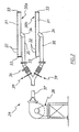
Fig. 4 is a schematic cross section side view of a modification of the apparatus ofFig. 1 ; -
Fig. 5 is a schematic illustration of a blower assembly employed in the apparatus ofFig. 4 ; and -
Fig. 6 is a schematic side elevation of a blower to be used with the apparatus ofFig. 4 . -
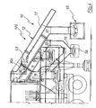
Fig. 1 shows anapparatus 10 according to a preferred embodiment of the present invention. Theapparatus 10 is shown attached to a tripledeck screen apparatus 100 and mounted on top of aflat bed trailer 120 havingwheels 121. - The
screen apparatus 100 includes an upperfirst screen 102, a middlesecond screen 104, a lowerthird screen 106 and achute 108 below thethird screen 106. Thescreens screen 102 has anoutlet 103, thesecond screen 104 has anoutlet 105, and thethird screen 106 has anoutlet 107. Adust conveyor 122 is mounted onto thetrailer 120 below thechute 108. - The
screen 100 can be any of the known multiple deck screens commercially available, such as the Cedar Rapids Triple Deck Screen. - The
apparatus 10 includes an upperfirst chute 12, amiddle second chute 14 and a lowerthird chute 16, each providing a duct along which the crushed concrete is to flow under the influence of gravity. Thechutes screens first chute 12 is angled downwardly and includes aninlet 50 and anoutlet 51 below and downstream from theinlet 50. Thefirst chute inlet 50 is connected to thefirst screen outlet 103. - The
second chute 14 is also angled downwardly, and includes aninlet 52, afirst outlet 15 below and downstream from theinlet 52, and asecond outlet 23. Thesecond chute inlet 52 is connected to thesecond screen outlet 105. Aconveyor 20 is arranged below thesecond chute outlet 15 and thelower outlet 23 connects to anoutlet 18. - The
third chute 16 includes an inlet 54, afirst outlet 21 below and downstream from the inlet 54, and a secondlower outlet 24. The third chute inlet 54 is connected to thethird screen outlet 107. Aconveyor 22 is arranged below thesecond chute outlet 21 and thelower outlet 24 connects to theoutlet 18. - The
second chute 14 includes ablower outlet 30a arranged immediately upstream of theoutlet 15 thereof and thethird chute 16 includes ablower outlet 30b arranged immediately upstream of theoutlet 21 thereof. Theblower outlets blower outlets retardation curtains 19. -
Fig. 2 shows ablower assembly 29 for theapparatus 10. Theblower assembly 29 includes ablower machine 38 having an outlet connected to afirst duct 37. Thefirst duct 37 includes a split end outlet, each outlet being connected tosecond ducts 36, which are respectively connected tothird ducts 35. Thethird ducts 35 are connected byelbow pipes 34 to mid-potions ofblower pipes 31. Theblower outlets Fig. 1 consist of thethird ducts 35,elbow pipes 34 and theblower pipes 31. Eachblower pipe 31 includesclosed end plates 33 at ends thereof and a number of spacedholes 32 formed along its length. The size of theholes 32 may vary depending on the air pressure required. The length of eachblower pipe 31 extends the width of the respectivesecond chute 14 orthird chute 16. - The
blower machine 38 is operable to supply high pressure air to theblower pipes 31, exiting same via the spaced holes 32.Slidable valves 39 are arranged at the outlets of thefirst duct 37, which are slidable from a fully open position (at which the first duct outlet is fully open) to a substantially closed position (at which the first duct outlet is substantially closed) such that the amount of air exiting thepipes 31 can be altered as desired. -
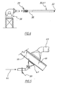
Fig. 3 shows ablower outlet assembly 60 for thefirst chute 12 of theapparatus 10. Theassembly 60 is an optional feature of theapparatus 10 and is not shown inFig, 1 . Theassembly 60 can be arranged below and downstream of theretardation curtain 19 of thefirst chute 12. Theblower outlet assembly 60 includes apipe 43 connected to atransition duct 42 which is connected to anopening 40 at the bottom wall of thechute 12. Amesh panel 41 extends across theopening 40. Abar 45 is disposed across thechute 12 immediately upstream and above theopening 40. Opposite to theopening 40, a rejectmaterial outlet opening 47 is formed in the upper wall of thechute 12.Baffle plates 46 extend from theopening 47 wider than theopening 40. Connected to theoutlet 47 is ahood 48 which leads to areject material duct 49. Thefirst chute 12 may also contain a blower pipe (the same as blower pipes 31). In other applications, all chutes may have a blower installed and the capacity of blowers may vary. - The
pipe duct 43 receives high pressure air from theblower 38 as indicated byarrow 44. Arranged in thepipe 43 is aslidable valve 39 for altering the volume of air exiting theopening 40. - The use of the
apparatus 10 will now be described. - Referring to
Fig. 1 , crushed concrete having impurities is poured onto thescreen apparatus 100. Thescreens screen 102 is sized to allow particles having dimensions less than 80 mm to pass therethrough onto thesecond screen 104. Particles having a dimension greater than 80 mm are moved by thescreen 102 onto itsoutlet 103. Thescreen 104 is sized to allow particles having dimensions less than 20 mm to pass therethrough onto thethird screen 106. Particles which have a dimension greater than 20 mm (but less than 80 mm due to the first screen 102) are moved by thescreen 104 onto itsoutlet 105. Thethird screen 106 allows particles having dimensions less than 10 mm to pass therethrough onto thechute 108 andconveyor 122. Particles having a dimension greater than 10 mm (but less than 20 mm due to the screen 104) are moved by thescreen 106 onto itsoutlet 107. In other applications, the size of the screens may be different and the particle sizes of 80mm, 20mm and 10mm are specific to this embodiment only. - The particles having dimensions less than 10 mm received by the
conveyor 122 are collected. At thethird screen outlet 107, the particles fall substantially as a sheet across the width of thescreen 106 into thechute 16 and across theblower outlet 30b. The natural path for the particles will be toward theoutlet 21. As mentioned above, theblower machine 38 forces high pressure air out through theblower outlets outlet 30b thus blows high pressure air across and through the falling particles. The impurities within the crushed concrete which are lighter than the concrete, such as wood and plastics, are forced by the air stream into thesecond outlet 24, whilst the heavier crushed concrete falls through into thefirst outlet 21. The impurities are thus substantially removed from the crushed concrete. The crushed concrete is collected by theconveyor 22 and the impurities fall into theoutlet 18. - At the
second screen outlet 105, the particles also fall substantially as a sheet across the width of thescreen 104 into thechute 14 and across theblower outlet 30a. The natural path for the particles will be toward theoutlet 15. Theoutlet 30a blows high pressure air across and through the falling particles. The impurities within the crushed concrete lighter than the concrete are forced by the air stream into thesecond outlet 23 and intooutlet 18, whilst the heavier crushed concrete falls through into thefirst outlet 15. The crushed concrete substantially free of impurities is collected by theconveyor 20. - At the
first screen outlet 103, the particles also fall substantially as a sheet across the width of thescreen 102 into thechute 12. If theapparatus 10 includes theblower outlet assembly 60, referring toFig. 3 , the particles fall along the bottom wall of thechute 12. The natural path for the particles will be toward theoutlet 51. The falling particles strike thebar 45 at which the particles are "bounced" into mid-air. As the particles are suspended in mid-air within thechute 12, high pressure air from theduct 43 is forced through the suspended particles. Thebaffles 46 substantially ensure that the air stream from theoutlet 40 are directed into theoutlet 47. Impurities lighter than the crushed concrete are blown into thehood 48 andduct 49, allowing the heavier concrete material to fall into thechute outlet 51. The crushed concrete collected at theoutlet 51 is sent to a crusher to be re-crushed and re-classified by thescreen apparatus 100. - The
apparatus 10 thus provides recycled 10 mm and 20 mm recycled concrete which is substantially free of impurities, or at the least, having significantly less impurities than previously available. - The sliding
valves 39 in theducts - The
retardation curtains 19 substantially spread the particles in a thin sheet-like layer and slow the speed of the particles falling down the chutes prior to theblower outlets apparatus 10. The operation of thescreen apparatus 100 can also assist in ensuring that the volume of particle output therefrom is not excessive. - Air is forced out substantially evenly along the length of the
pipes 31 of theoutlets apparatus 10. In the embodiment, thepipes 31 have a diameter of 114.3 mm and a thickness of 4.5 mm. Theholes 32 are 10 mm in diameter and spaced 20 mm apart. Theholes 32 are countersunk and de-burred on the inside. Theoutlet pipes 31 are axially rotated such that theholes 32 are at an angle of about 23° to the horizontal. This has been found to be the most effective angle for theapparatus 10. - The
elbow pipes 34 are standard 90° elbows. Thethird ducts 35 are made from the same material as thepipes 31. Thesecond duct 36 has a diameter of 127 mm and is made from flexible plastics material (eg. PVC) having a concertina fold therein to reduce vibration in theduct 36. Thefirst duct 37 is made from galvanized steel and has a diameter of 125 mm. Theblower 38 in the embodiment is mounted on a free-standing support structure and has the capacity of blowing 2500 cfm of air at a pressure of 42" WC. - The
chutes - Other materials that can be blown are bricks, tiles, pavers, masonry blocks, roof tiles and glass.
- Although preferred embodiments of the present invention have been described, it will be apparent to skilled persons that modifications can be made to the above embodiments or that the present invention can be embodied in other forms.
- For example, instead of utilizing a
single blower 38, multiple blowers can be used in the present invention, one for eachoutlet blower 38 is shown inFig. 6 . Also, the present invention can be installed in a permanent recycling facility, rather than on a trailer. In theblower assembly 29, it is also possible to simply connect thesecond duct 36 to an end of thepipes 31 and not use thethird ducts 35 andelbow pipe 34. This arrangement can be used if there is insufficient space to insert theoutlets apparatus 10. Such an arrangement however is less preferred as it does not provide an even output of air along the length of thepipes 31. - In
Figs. 4 to 6 there is schematically depicted a modification of theapparatus 10. In this example, theupper chute 12 also includes theinlet 50 and theoutlet 51 however intermediate thereof is animpurities outlet 53 on one side of thechute 12, while opposite theoutlet 53 is ablower outlet 30c. Theoutlet 53 communicates with achute 17 down which impurities are ducted. - The
outlet 51 delivers crushed concrete to aconveyor 55, with theoutlets single conveyor 56. - In this embodiment each
blower 38 delivers air to a single blower outlet 30. Also in this embodiment only asingle baffle 46 is employed, thatbaffle 46 being down stream of theoutlet 41. The same can be applied to the other prior outlets. - In the above embodiments, the
ducts duct 14 above theduct 16, and theduct 12 above theduct 14. - The above embodiments are described with reference to processing crushed concrete. In that regard the above embodiments could be adapted to process the crushed materials to be recycled.
Claims (6)
- An assembly (10) to remove impurities from crushed material that is to be recycled, the assembly (10) including:a first chute (12) and a second chute (14), each chute (12, 14) including:an interior along which the crushed material passes under the influence of gravity,an impurities outlet (47, 23) disposed on a first side of the chute (12,14), andan air outlet (40, 30a) disposed on a side of the chute (12, 14) opposite said impurities outlet (47, 23) so that an air stream entering said interior from said air outlet (40, 30a) passes across said interior towards said impurities outlet (47, 23);and a blower means (38) connected to each air outlet (40, 30a) to deliver air thereto so that air passes through the crushed material passing along the associated chute (12, 14) to engage the impurities to deliver the impurities to the associated impurities outlet (47, 23) while permitting crushed material to continue along said associated chute (12, 14),characterized in that said assembly (10) comprises:a first screen (102) to which the crushed material is delivered, said first screen (102) having an outlet (103);a second screen (104) to which crushed material passing through the first screen (102) is delivered, said second screen (104) having an outlet (105),and in thatsaid first chute (12) is positioned to receive crushed material passing through said first screen (102) outlet (103);said second chute (14) is positioned to receive crushed material passing through said second screen (104) outlet (105).
- The assembly (10) of claim 1, wherein each chute (12, 14) is inclined to the horizontal by an acute angle so that each impurities outlet (47, 23) is above the associated air outlet (40, 30a).
- The assembly (10) of claim 1 or 2, wherein each chute (12, 14) has a transverse width, and each air outlet (40, 30a) extends across the width of the associated chute (12,14).
- The assembly (10) of claim 1, 2 or 3, wherein each chute (12, 14) includes a speed retarding means (19) to retard speed of crushed material passing along the chute (12, 14), each retarding means (19) being located upstream of the associated air outlet (40, 30a).
- The assembly (10) of any one of claims 1 to 4, wherein each air outlet (40, 30a) is configured so that the air issuing therefrom is evenly distributed across the associated chute (12, 14).
- The assembly (10) of any one of claims 1 to 5, further including means to adjust air flow rate delivered to each air outlet (40, 30a).
Applications Claiming Priority (2)
| Application Number | Priority Date | Filing Date | Title |
|---|---|---|---|
| AU2005904700A AU2005904700A0 (en) | 2005-08-29 | Apparatus and method for removing impurities in crushed recycled concrete | |
| PCT/AU2006/000947 WO2007025324A1 (en) | 2005-08-29 | 2006-07-05 | Apparatus and method for removing impurities in crushed recycled material |
Publications (3)
| Publication Number | Publication Date |
|---|---|
| EP1919634A1 EP1919634A1 (en) | 2008-05-14 |
| EP1919634A4 EP1919634A4 (en) | 2009-08-19 |
| EP1919634B1 true EP1919634B1 (en) | 2010-09-01 |
Family
ID=37808395
Family Applications (1)
| Application Number | Title | Priority Date | Filing Date |
|---|---|---|---|
| EP06752672A Active EP1919634B1 (en) | 2005-08-29 | 2006-07-05 | Assembly for removing impurities in crushed recycled material |
Country Status (7)
| Country | Link |
|---|---|
| US (1) | US8109392B2 (en) |
| EP (1) | EP1919634B1 (en) |
| AT (1) | ATE479508T1 (en) |
| CA (1) | CA2620595A1 (en) |
| DE (1) | DE602006016618D1 (en) |
| ES (1) | ES2352146T3 (en) |
| WO (1) | WO2007025324A1 (en) |
Families Citing this family (1)
| Publication number | Priority date | Publication date | Assignee | Title |
|---|---|---|---|---|
| JP6469912B1 (en) * | 2018-02-27 | 2019-02-13 | 株式会社メタルドゥ | Titanium cobble manufacturing method and manufacturing apparatus |
Family Cites Families (15)
| Publication number | Priority date | Publication date | Assignee | Title |
|---|---|---|---|---|
| US603448A (en) * | 1898-05-03 | Machine for cleaning cotton-seed | ||
| GB227528A (en) * | 1923-10-18 | 1925-01-19 | Shelton Iron Steel And Coal Co | Improvements in or relating to the treatment of coal |
| US2203821A (en) | 1938-03-02 | 1940-06-11 | Zonolite Company | Vermiculite processing machine |
| US2200472A (en) * | 1938-06-29 | 1940-05-14 | Schering Corp | Granular material separating machine |
| US3622089A (en) * | 1969-12-04 | 1971-11-23 | Johnson Welding & Equipment Co | Crushing plant |
| JPS5247183B2 (en) * | 1972-09-04 | 1977-11-30 | ||
| US3909873A (en) * | 1973-08-15 | 1975-10-07 | Alexandr Nikolaevich Minasov | Device for dedusting loose materials |
| GB1419337A (en) * | 1973-08-29 | 1975-12-31 | Gvi Proekt Predreijaty Koksokh | Device for dedusting loose materials |
| DE3126585C2 (en) * | 1981-07-06 | 1983-08-04 | Rheinische Braunkohlenwerke AG, 5000 Köln | Process for separating sand from a sand-containing, dried lignite pile |
| US4631124A (en) | 1983-05-18 | 1986-12-23 | Paulson Jerome I | Kinetic gravity deduster |
| US5344025A (en) | 1991-04-24 | 1994-09-06 | Griffin & Company | Commingled waste separation apparatus and methods |
| US5992774A (en) * | 1998-03-16 | 1999-11-30 | Insun Company, Ltd. | Method and system for recycling construction waste articles |
| JP4480107B2 (en) * | 2000-05-29 | 2010-06-16 | 日工株式会社 | Sorting and processing equipment for empty cans |
| US7478771B2 (en) * | 2005-08-03 | 2009-01-20 | Vulcan Materials Company | Methods for recrushing rocks and removing fines therefrom |
| JP5255799B2 (en) * | 2007-09-04 | 2013-08-07 | コトブキ技研工業株式会社 | Sand making apparatus, sand making method and sand making |
-
2006
- 2006-07-05 EP EP06752672A patent/EP1919634B1/en active Active
- 2006-07-05 CA CA002620595A patent/CA2620595A1/en not_active Abandoned
- 2006-07-05 ES ES06752672T patent/ES2352146T3/en active Active
- 2006-07-05 US US11/990,879 patent/US8109392B2/en active Active
- 2006-07-05 AT AT06752672T patent/ATE479508T1/en not_active IP Right Cessation
- 2006-07-05 DE DE602006016618T patent/DE602006016618D1/en active Active
- 2006-07-05 WO PCT/AU2006/000947 patent/WO2007025324A1/en not_active Ceased
Also Published As
| Publication number | Publication date |
|---|---|
| WO2007025324A1 (en) | 2007-03-08 |
| EP1919634A4 (en) | 2009-08-19 |
| CA2620595A1 (en) | 2007-03-08 |
| DE602006016618D1 (en) | 2010-10-14 |
| EP1919634A1 (en) | 2008-05-14 |
| ES2352146T3 (en) | 2011-02-16 |
| ATE479508T1 (en) | 2010-09-15 |
| US20110056872A1 (en) | 2011-03-10 |
| US8109392B2 (en) | 2012-02-07 |
Similar Documents
| Publication | Publication Date | Title |
|---|---|---|
| CN103118808B (en) | separation equipment | |
| US20080296417A1 (en) | Aggregate recycling apparatus having air circulation type foreign substance and fine particle separation means, and method thereof | |
| RU2456099C2 (en) | Pneumatic vacuum separator of loose materials | |
| CN204035035U (en) | Mineral sorting device and mineral processing system | |
| CN104438088B (en) | Material dispersing and dedusting device and method and its air inlet structure, air vibrating screen | |
| US5308368A (en) | System for separation of materials using suction air power | |
| AU2006287101B2 (en) | Apparatus and method for removing impurities in crushed recycled material | |
| US8109392B2 (en) | Apparatus and method for removing impurities in crushed recycled material | |
| CN220027779U (en) | Winnowing powder removing machine | |
| KR100793166B1 (en) | Debris and Dedusting Device of Construction Waste | |
| CN216965388U (en) | Air screen device | |
| CN212069520U (en) | Waste recovery winnowing device for highway construction | |
| CN105436084A (en) | Mineral sorting device and mineral processing system | |
| CN213967725U (en) | Fine material sorting and dedusting system | |
| CN212791905U (en) | Vermiculite screening plant | |
| JP2803996B2 (en) | Waste sorting equipment | |
| EP1337305A1 (en) | Method and device for dry separating light and heavy fractions of a granulometrically presieved building rubble mixture | |
| CN206701519U (en) | Atomizer cyclone separator | |
| RU2341438C2 (en) | Method of dust generating equipment aspiration and system for its realisation | |
| RU2060060C1 (en) | Pneumatic classifier | |
| CN223454621U (en) | Composite sorting equipment | |
| KR100444289B1 (en) | Foreign material quality sorting system of construction waste | |
| JP3035200B2 (en) | Waste sorting equipment | |
| AU733609B2 (en) | Particle conditioning method and apparatus | |
| JP3325502B2 (en) | Waste sorting equipment |
Legal Events
| Date | Code | Title | Description |
|---|---|---|---|
| PUAI | Public reference made under article 153(3) epc to a published international application that has entered the european phase |
Free format text: ORIGINAL CODE: 0009012 |
|
| 17P | Request for examination filed |
Effective date: 20080228 |
|
| AK | Designated contracting states |
Kind code of ref document: A1 Designated state(s): AT BE BG CH CY CZ DE DK EE ES FI FR GB GR HU IE IS IT LI LT LU LV MC NL PL PT RO SE SI SK TR |
|
| A4 | Supplementary search report drawn up and despatched |
Effective date: 20090716 |
|
| 17Q | First examination report despatched |
Effective date: 20090915 |
|
| GRAP | Despatch of communication of intention to grant a patent |
Free format text: ORIGINAL CODE: EPIDOSNIGR1 |
|
| RIC1 | Information provided on ipc code assigned before grant |
Ipc: B07B 7/01 20060101ALI20100204BHEP Ipc: B07B 4/02 20060101AFI20100204BHEP Ipc: B07B 9/02 20060101ALI20100204BHEP |
|
| RTI1 | Title (correction) |
Free format text: ASSEMBLY FOR REMOVING IMPURITIES IN CRUSHED RECYCLED MATERIAL |
|
| GRAS | Grant fee paid |
Free format text: ORIGINAL CODE: EPIDOSNIGR3 |
|
| GRAA | (expected) grant |
Free format text: ORIGINAL CODE: 0009210 |
|
| AK | Designated contracting states |
Kind code of ref document: B1 Designated state(s): AT BE BG CH CY CZ DE DK EE ES FI FR GB GR HU IE IS IT LI LT LU LV MC NL PL PT RO SE SI SK TR |
|
| REG | Reference to a national code |
Ref country code: GB Ref legal event code: FG4D |
|
| REG | Reference to a national code |
Ref country code: CH Ref legal event code: EP |
|
| REG | Reference to a national code |
Ref country code: IE Ref legal event code: FG4D |
|
| REF | Corresponds to: |
Ref document number: 602006016618 Country of ref document: DE Date of ref document: 20101014 Kind code of ref document: P |
|
| REG | Reference to a national code |
Ref country code: DE Ref legal event code: R096 Ref document number: 602006016618 Country of ref document: DE Effective date: 20101014 |
|
| REG | Reference to a national code |
Ref country code: NL Ref legal event code: VDEP Effective date: 20100901 |
|
| PG25 | Lapsed in a contracting state [announced via postgrant information from national office to epo] |
Ref country code: AT Free format text: LAPSE BECAUSE OF FAILURE TO SUBMIT A TRANSLATION OF THE DESCRIPTION OR TO PAY THE FEE WITHIN THE PRESCRIBED TIME-LIMIT Effective date: 20100901 Ref country code: LT Free format text: LAPSE BECAUSE OF FAILURE TO SUBMIT A TRANSLATION OF THE DESCRIPTION OR TO PAY THE FEE WITHIN THE PRESCRIBED TIME-LIMIT Effective date: 20100901 Ref country code: FI Free format text: LAPSE BECAUSE OF FAILURE TO SUBMIT A TRANSLATION OF THE DESCRIPTION OR TO PAY THE FEE WITHIN THE PRESCRIBED TIME-LIMIT Effective date: 20100901 |
|
| REG | Reference to a national code |
Ref country code: ES Ref legal event code: FG2A Effective date: 20110204 |
|
| LTIE | Lt: invalidation of european patent or patent extension |
Effective date: 20100901 |
|
| PG25 | Lapsed in a contracting state [announced via postgrant information from national office to epo] |
Ref country code: PL Free format text: LAPSE BECAUSE OF FAILURE TO SUBMIT A TRANSLATION OF THE DESCRIPTION OR TO PAY THE FEE WITHIN THE PRESCRIBED TIME-LIMIT Effective date: 20100901 Ref country code: SI Free format text: LAPSE BECAUSE OF FAILURE TO SUBMIT A TRANSLATION OF THE DESCRIPTION OR TO PAY THE FEE WITHIN THE PRESCRIBED TIME-LIMIT Effective date: 20100901 Ref country code: CY Free format text: LAPSE BECAUSE OF FAILURE TO SUBMIT A TRANSLATION OF THE DESCRIPTION OR TO PAY THE FEE WITHIN THE PRESCRIBED TIME-LIMIT Effective date: 20100901 |
|
| PG25 | Lapsed in a contracting state [announced via postgrant information from national office to epo] |
Ref country code: SE Free format text: LAPSE BECAUSE OF FAILURE TO SUBMIT A TRANSLATION OF THE DESCRIPTION OR TO PAY THE FEE WITHIN THE PRESCRIBED TIME-LIMIT Effective date: 20100901 Ref country code: LV Free format text: LAPSE BECAUSE OF FAILURE TO SUBMIT A TRANSLATION OF THE DESCRIPTION OR TO PAY THE FEE WITHIN THE PRESCRIBED TIME-LIMIT Effective date: 20100901 Ref country code: GR Free format text: LAPSE BECAUSE OF FAILURE TO SUBMIT A TRANSLATION OF THE DESCRIPTION OR TO PAY THE FEE WITHIN THE PRESCRIBED TIME-LIMIT Effective date: 20101202 Ref country code: NL Free format text: LAPSE BECAUSE OF FAILURE TO SUBMIT A TRANSLATION OF THE DESCRIPTION OR TO PAY THE FEE WITHIN THE PRESCRIBED TIME-LIMIT Effective date: 20100901 |
|
| PG25 | Lapsed in a contracting state [announced via postgrant information from national office to epo] |
Ref country code: PT Free format text: LAPSE BECAUSE OF FAILURE TO SUBMIT A TRANSLATION OF THE DESCRIPTION OR TO PAY THE FEE WITHIN THE PRESCRIBED TIME-LIMIT Effective date: 20110103 Ref country code: CZ Free format text: LAPSE BECAUSE OF FAILURE TO SUBMIT A TRANSLATION OF THE DESCRIPTION OR TO PAY THE FEE WITHIN THE PRESCRIBED TIME-LIMIT Effective date: 20100901 Ref country code: EE Free format text: LAPSE BECAUSE OF FAILURE TO SUBMIT A TRANSLATION OF THE DESCRIPTION OR TO PAY THE FEE WITHIN THE PRESCRIBED TIME-LIMIT Effective date: 20100901 Ref country code: IT Free format text: LAPSE BECAUSE OF FAILURE TO SUBMIT A TRANSLATION OF THE DESCRIPTION OR TO PAY THE FEE WITHIN THE PRESCRIBED TIME-LIMIT Effective date: 20100901 Ref country code: SK Free format text: LAPSE BECAUSE OF FAILURE TO SUBMIT A TRANSLATION OF THE DESCRIPTION OR TO PAY THE FEE WITHIN THE PRESCRIBED TIME-LIMIT Effective date: 20100901 Ref country code: IS Free format text: LAPSE BECAUSE OF FAILURE TO SUBMIT A TRANSLATION OF THE DESCRIPTION OR TO PAY THE FEE WITHIN THE PRESCRIBED TIME-LIMIT Effective date: 20110101 Ref country code: RO Free format text: LAPSE BECAUSE OF FAILURE TO SUBMIT A TRANSLATION OF THE DESCRIPTION OR TO PAY THE FEE WITHIN THE PRESCRIBED TIME-LIMIT Effective date: 20100901 |
|
| PG25 | Lapsed in a contracting state [announced via postgrant information from national office to epo] |
Ref country code: BE Free format text: LAPSE BECAUSE OF FAILURE TO SUBMIT A TRANSLATION OF THE DESCRIPTION OR TO PAY THE FEE WITHIN THE PRESCRIBED TIME-LIMIT Effective date: 20100901 |
|
| PLBE | No opposition filed within time limit |
Free format text: ORIGINAL CODE: 0009261 |
|
| STAA | Information on the status of an ep patent application or granted ep patent |
Free format text: STATUS: NO OPPOSITION FILED WITHIN TIME LIMIT |
|
| 26N | No opposition filed |
Effective date: 20110606 |
|
| PG25 | Lapsed in a contracting state [announced via postgrant information from national office to epo] |
Ref country code: DK Free format text: LAPSE BECAUSE OF FAILURE TO SUBMIT A TRANSLATION OF THE DESCRIPTION OR TO PAY THE FEE WITHIN THE PRESCRIBED TIME-LIMIT Effective date: 20100901 |
|
| REG | Reference to a national code |
Ref country code: DE Ref legal event code: R097 Ref document number: 602006016618 Country of ref document: DE Effective date: 20110606 |
|
| PG25 | Lapsed in a contracting state [announced via postgrant information from national office to epo] |
Ref country code: MC Free format text: LAPSE BECAUSE OF NON-PAYMENT OF DUE FEES Effective date: 20110731 |
|
| REG | Reference to a national code |
Ref country code: CH Ref legal event code: PL |
|
| REG | Reference to a national code |
Ref country code: IE Ref legal event code: MM4A |
|
| PG25 | Lapsed in a contracting state [announced via postgrant information from national office to epo] |
Ref country code: LI Free format text: LAPSE BECAUSE OF NON-PAYMENT OF DUE FEES Effective date: 20110731 Ref country code: CH Free format text: LAPSE BECAUSE OF NON-PAYMENT OF DUE FEES Effective date: 20110731 |
|
| PG25 | Lapsed in a contracting state [announced via postgrant information from national office to epo] |
Ref country code: IE Free format text: LAPSE BECAUSE OF NON-PAYMENT OF DUE FEES Effective date: 20110705 |
|
| PG25 | Lapsed in a contracting state [announced via postgrant information from national office to epo] |
Ref country code: LU Free format text: LAPSE BECAUSE OF NON-PAYMENT OF DUE FEES Effective date: 20110705 |
|
| PG25 | Lapsed in a contracting state [announced via postgrant information from national office to epo] |
Ref country code: BG Free format text: LAPSE BECAUSE OF FAILURE TO SUBMIT A TRANSLATION OF THE DESCRIPTION OR TO PAY THE FEE WITHIN THE PRESCRIBED TIME-LIMIT Effective date: 20101201 Ref country code: TR Free format text: LAPSE BECAUSE OF FAILURE TO SUBMIT A TRANSLATION OF THE DESCRIPTION OR TO PAY THE FEE WITHIN THE PRESCRIBED TIME-LIMIT Effective date: 20100901 |
|
| PG25 | Lapsed in a contracting state [announced via postgrant information from national office to epo] |
Ref country code: HU Free format text: LAPSE BECAUSE OF FAILURE TO SUBMIT A TRANSLATION OF THE DESCRIPTION OR TO PAY THE FEE WITHIN THE PRESCRIBED TIME-LIMIT Effective date: 20100901 |
|
| REG | Reference to a national code |
Ref country code: FR Ref legal event code: PLFP Year of fee payment: 11 |
|
| REG | Reference to a national code |
Ref country code: FR Ref legal event code: PLFP Year of fee payment: 12 |
|
| REG | Reference to a national code |
Ref country code: FR Ref legal event code: PLFP Year of fee payment: 13 |
|
| REG | Reference to a national code |
Ref country code: DE Ref legal event code: R082 Ref document number: 602006016618 Country of ref document: DE Representative=s name: CBDL PATENTANWAELTE GBR, DE Ref country code: DE Ref legal event code: R082 Ref document number: 602006016618 Country of ref document: DE Representative=s name: CBDL PATENTANWAELTE EGBR, DE |
|
| PGFP | Annual fee paid to national office [announced via postgrant information from national office to epo] |
Ref country code: ES Payment date: 20250806 Year of fee payment: 20 |
|
| PGFP | Annual fee paid to national office [announced via postgrant information from national office to epo] |
Ref country code: DE Payment date: 20250702 Year of fee payment: 20 |
|
| PGFP | Annual fee paid to national office [announced via postgrant information from national office to epo] |
Ref country code: GB Payment date: 20250703 Year of fee payment: 20 |
|
| PGFP | Annual fee paid to national office [announced via postgrant information from national office to epo] |
Ref country code: FR Payment date: 20250703 Year of fee payment: 20 |