EP1919622B1 - Systems, apparatus and methods for vacuum filtration - Google Patents
Systems, apparatus and methods for vacuum filtration Download PDFInfo
- Publication number
- EP1919622B1 EP1919622B1 EP06802979.2A EP06802979A EP1919622B1 EP 1919622 B1 EP1919622 B1 EP 1919622B1 EP 06802979 A EP06802979 A EP 06802979A EP 1919622 B1 EP1919622 B1 EP 1919622B1
- Authority
- EP
- European Patent Office
- Prior art keywords
- base
- receptacle
- vacuum
- adapter
- filtering apparatus
- Prior art date
- Legal status (The legal status is an assumption and is not a legal conclusion. Google has not performed a legal analysis and makes no representation as to the accuracy of the status listed.)
- Not-in-force
Links
- 238000000034 method Methods 0.000 title claims description 16
- 238000003828 vacuum filtration Methods 0.000 title description 29
- 238000001914 filtration Methods 0.000 claims description 168
- 239000007788 liquid Substances 0.000 claims description 95
- 239000012530 fluid Substances 0.000 claims description 14
- 238000004891 communication Methods 0.000 claims description 11
- 239000006143 cell culture medium Substances 0.000 claims description 6
- 230000008878 coupling Effects 0.000 claims description 5
- 238000010168 coupling process Methods 0.000 claims description 5
- 238000005859 coupling reaction Methods 0.000 claims description 5
- 238000007789 sealing Methods 0.000 claims 1
- 238000011144 upstream manufacturing Methods 0.000 description 9
- 239000000463 material Substances 0.000 description 8
- -1 polypropylene Polymers 0.000 description 4
- 229920000515 polycarbonate Polymers 0.000 description 3
- 239000004417 polycarbonate Substances 0.000 description 3
- 239000004698 Polyethylene Substances 0.000 description 2
- 239000004743 Polypropylene Substances 0.000 description 2
- PPBRXRYQALVLMV-UHFFFAOYSA-N Styrene Chemical compound C=CC1=CC=CC=C1 PPBRXRYQALVLMV-UHFFFAOYSA-N 0.000 description 2
- NIXOWILDQLNWCW-UHFFFAOYSA-N acrylic acid group Chemical group C(C=C)(=O)O NIXOWILDQLNWCW-UHFFFAOYSA-N 0.000 description 2
- 239000003292 glue Substances 0.000 description 2
- 229920000573 polyethylene Polymers 0.000 description 2
- 229920001155 polypropylene Polymers 0.000 description 2
- 239000002904 solvent Substances 0.000 description 2
- 238000013022 venting Methods 0.000 description 2
- 239000004593 Epoxy Substances 0.000 description 1
- JOYRKODLDBILNP-UHFFFAOYSA-N Ethyl urethane Chemical compound CCOC(N)=O JOYRKODLDBILNP-UHFFFAOYSA-N 0.000 description 1
- 239000000020 Nitrocellulose Substances 0.000 description 1
- 239000004677 Nylon Substances 0.000 description 1
- 239000002033 PVDF binder Substances 0.000 description 1
- 239000004809 Teflon Substances 0.000 description 1
- 229920006362 Teflon® Polymers 0.000 description 1
- FJWGYAHXMCUOOM-QHOUIDNNSA-N [(2s,3r,4s,5r,6r)-2-[(2r,3r,4s,5r,6s)-4,5-dinitrooxy-2-(nitrooxymethyl)-6-[(2r,3r,4s,5r,6s)-4,5,6-trinitrooxy-2-(nitrooxymethyl)oxan-3-yl]oxyoxan-3-yl]oxy-3,5-dinitrooxy-6-(nitrooxymethyl)oxan-4-yl] nitrate Chemical class O([C@@H]1O[C@@H]([C@H]([C@H](O[N+]([O-])=O)[C@H]1O[N+]([O-])=O)O[C@H]1[C@@H]([C@@H](O[N+]([O-])=O)[C@H](O[N+]([O-])=O)[C@@H](CO[N+]([O-])=O)O1)O[N+]([O-])=O)CO[N+](=O)[O-])[C@@H]1[C@@H](CO[N+]([O-])=O)O[C@@H](O[N+]([O-])=O)[C@H](O[N+]([O-])=O)[C@H]1O[N+]([O-])=O FJWGYAHXMCUOOM-QHOUIDNNSA-N 0.000 description 1
- XAGFODPZIPBFFR-UHFFFAOYSA-N aluminium Chemical compound [Al] XAGFODPZIPBFFR-UHFFFAOYSA-N 0.000 description 1
- 229910052782 aluminium Inorganic materials 0.000 description 1
- 229920002678 cellulose Polymers 0.000 description 1
- 239000001913 cellulose Substances 0.000 description 1
- 229920002301 cellulose acetate Chemical class 0.000 description 1
- 230000000295 complement effect Effects 0.000 description 1
- 230000001419 dependent effect Effects 0.000 description 1
- 150000002148 esters Chemical class 0.000 description 1
- 239000011521 glass Substances 0.000 description 1
- 239000003365 glass fiber Substances 0.000 description 1
- 230000002209 hydrophobic effect Effects 0.000 description 1
- 239000000203 mixture Chemical class 0.000 description 1
- 238000012986 modification Methods 0.000 description 1
- 230000004048 modification Effects 0.000 description 1
- 229920001220 nitrocellulos Polymers 0.000 description 1
- 229920001778 nylon Polymers 0.000 description 1
- 239000004033 plastic Substances 0.000 description 1
- 229920003023 plastic Polymers 0.000 description 1
- 229920002492 poly(sulfone) Polymers 0.000 description 1
- 229920002981 polyvinylidene fluoride Polymers 0.000 description 1
- 229910001220 stainless steel Inorganic materials 0.000 description 1
- 239000010935 stainless steel Substances 0.000 description 1
- 238000012360 testing method Methods 0.000 description 1
Images


Classifications
-
- G—PHYSICS
- G01—MEASURING; TESTING
- G01N—INVESTIGATING OR ANALYSING MATERIALS BY DETERMINING THEIR CHEMICAL OR PHYSICAL PROPERTIES
- G01N1/00—Sampling; Preparing specimens for investigation
- G01N1/28—Preparing specimens for investigation including physical details of (bio-)chemical methods covered elsewhere, e.g. G01N33/50, C12Q
- G01N1/40—Concentrating samples
- G01N1/4077—Concentrating samples by other techniques involving separation of suspended solids
-
- B—PERFORMING OPERATIONS; TRANSPORTING
- B01—PHYSICAL OR CHEMICAL PROCESSES OR APPARATUS IN GENERAL
- B01D—SEPARATION
- B01D29/00—Filters with filtering elements stationary during filtration, e.g. pressure or suction filters, not covered by groups B01D24/00 - B01D27/00; Filtering elements therefor
- B01D29/085—Funnel filters; Holders therefor
-
- B—PERFORMING OPERATIONS; TRANSPORTING
- B01—PHYSICAL OR CHEMICAL PROCESSES OR APPARATUS IN GENERAL
- B01D—SEPARATION
- B01D2201/00—Details relating to filtering apparatus
- B01D2201/20—Pressure-related systems for filters
- B01D2201/204—Systems for applying vacuum to filters
-
- B—PERFORMING OPERATIONS; TRANSPORTING
- B01—PHYSICAL OR CHEMICAL PROCESSES OR APPARATUS IN GENERAL
- B01L—CHEMICAL OR PHYSICAL LABORATORY APPARATUS FOR GENERAL USE
- B01L3/00—Containers or dishes for laboratory use, e.g. laboratory glassware; Droppers
- B01L3/56—Labware specially adapted for transferring fluids
- B01L3/563—Joints or fittings ; Separable fluid transfer means to transfer fluids between at least two containers, e.g. connectors
-
- G—PHYSICS
- G01—MEASURING; TESTING
- G01N—INVESTIGATING OR ANALYSING MATERIALS BY DETERMINING THEIR CHEMICAL OR PHYSICAL PROPERTIES
- G01N35/00—Automatic analysis not limited to methods or materials provided for in any single one of groups G01N1/00 - G01N33/00; Handling materials therefor
- G01N35/10—Devices for transferring samples or any liquids to, in, or from, the analysis apparatus, e.g. suction devices, injection devices
- G01N2035/1027—General features of the devices
- G01N2035/1048—General features of the devices using the transfer device for another function
- G01N2035/1053—General features of the devices using the transfer device for another function for separating part of the liquid, e.g. filters, extraction phase
Description
- This invention relates to the filtration field, and more particularly, to a disposable vacuum filtration device and reusable apparatus capable of filtering liquid samples.
- Many disposable vacuum filtration devices for filtering liquid samples are available today. The currently available disposable vacuum filtration devices for filtering liquid samples may include a receptacle for collecting the filtered liquid, a removable funnel section that contains a filter element, a removable lid that caps the top of the funnel section, and a cap for the receiving container to cap the container after the funnel section has been removed. The funnel section contains a filter support that provides support for the filter element and provides fluid flow communication between the downstream side of the filter clement and the interior of the receptacle. The funnel section also contains a vacuum port, and a way to apply a vacuum to the interior of the receptacle. The outer periphery of the filter element is sealed to the device to prevent un-filtered liquid from entering the receptacle. The removable lid is press fitted onto the top of the removable funnel section typically with a fit that allows easy removal, but does not allow the lid to accidentally separate from the funnel section. These devices are normally sold pre-sterilized.
- In use, the end user removes a sterile vacuum filtration device from its shipping package in a laminar flow hood to prevent contaminating the device. The lid is then removed from the funnel section and a liquid sample to be filtered is poured into the funnel section. The lid is then placed back onto the funnel section and the vacuum port of the funnel section is connected to a vacuum source. The vacuum source pulls the liquid through the filter element and into the receptacle. Either the lid or the funnel section may contain venting to allow air to replace the liquid in the funnel as the vacuum removes the liquid from the funnel.
- After all of the liquid sample has been pulled into the receptacle, the user removes the funnel section from the receptacle and places the cap onto the receptacle to keep the contents sterile. The funnel section may then be discarded.
- Reference is made to
US 6,491,873 B2 . The two-part form inclaim 1 is based on this document. Further reference is made toUS 6,159,368 A ,US 2005/0178 216 A1 andUS 5,948,246 A . - The invention is defined by the independent claims below. Dependent claims are directed to optional features and preferred embodiments.
- One embodiment of the present invention is directed to a liquid filtering system. The system of this embodiment includes a filtering apparatus having a receiving receptacle coupled with an adapter. The adapter has an adapter port for receiving a vacuum and an interface for coupling with an output receptacle for receiving filtered liquid from the filtering apparatus. The adapter is between the receiving receptacle and output receptacle when the output receptacle is coupled with the adapter interface. The system also includes a base having a substantially rigid housing containing an internal vacuum channel terminating at a base vacuum delivery port. The base has a support for supporting the filtering apparatus. In this embodiment, the adapter is couplable with the base to connect the adapter port to the base vacuum delivery port.
- The system may include a cell culture medium filter for filtering a liquid received by the receiving receptacle.
- When the output receptacle is coupled with the adapter interface, the base may suspend the output receptacle above a bottom portion of the base to form a gap therebetween.
- The housing may define the vacuum channel.
- The base has a bottom portion and the output receptacle may be spaced from the bottom portion.
- The vacuum channel is contained substantially entirely within the base and can connect with the adapter to provide a vacuum.
- The base may be removably couplable with the filtering apparatus. The filtering apparatus and the base can have corresponding registration details for orienting the adapter in a manner that connects the vacuum channel with the adapter.
- The adapter includes an adaptor port, may be removably couplable with the base, and may have a first registration detail for orienting the adapter in a manner that connects the base vacuum channel with the adapter port.
- Also disclosed is a support base for supporting a filtering apparatus coupled with an output receptacle. The support base includes a substantially rigid housing containing a vacuum channel and a support for supporting the filtering apparatus. At least one of the housing and support can have a base registration detail for orienting the filtering apparatus in a manner that connects the base vacuum channel with the filtering apparatus port. The support is upstream of the output receptacle when supporting the filtering apparatus. The support base includes a support for removably coupling with the filtering apparatus. The vacuum channel is connected to the filtering apparatus port when the support couples with the filtering apparatus. The support is upstream of at least a portion of the output receptacle when the support couples with the filtering apparatus.
- Also diclosed is a method of filtering a cell culture medium. The filtering apparatus may fit in registry with corresponding registry details of the base to orient the filtering apparatus port with the vacuum channel in the base.
- Also disclosed is a vacuum filtration apparatus including a disposable filtration device. The filtration device includes a disposable filtration funnel capable of holding un-filtered liquid therein, a receptacle disposed below said funnel, said receptacle including a single opening located at the top of said receptacle, a filter disposed between the un-filtered liquid and the top of the disposable receptacle, with said filtered sealed to said filtration device to prevent the flow of un-filtered liquid into said receptacle, and an inlet that is not a part of the receptacle, in fluid flow communication with said opening of said receptacle. The apparatus also includes a reusable base releasably supporting said vacuum filtration device, and having an opening through which vacuum may be applied to said base, with the vacuum of said base being automatically applied to said inlet of said disposable filtration device when the disposable filtration device is placed onto the reusable base, thereby drawing liquid from said funnel, through said filter, into said filtration receptacle.
- Also disclosed is a vacuum filtration apparatus including a disposable filtration device that includes a disposable filtration funnel capable of holding un-filtered liquid, a disposable receptacle disposed below said funnel, said receptacle including a single opening located at the top of said receptacle, a filter disposed between the un-filtered liquid and the top of the disposable receptacle, with said filtered sealed with a non-releasable seal to said filtration device to prevent the flow of un-filtered liquid into said receptacle. The apparatus also includes a reusable base releasably supporting said vacuum filtration device, and having an opening through which vacuum may be applied to said base. The reusable base is operatively connected to the interior of said filtration receptacle so that the vacuum of said base may be applied to said filtration receptacle to draw liquid from said funnel, through said filter, into said filtration receptacle.
- Also disclosed is a vacuum filtration apparatus that includes a disposable filtration device which includes a disposable filtration funnel capable of holding un-filtered liquid, a receptacle disposed below said funnel, said receptacle including a single opening located at the top of said receptacle, with the receptacle releasably attached to the funnel, and a filter disposed between the un-filtered liquid and the top of the disposable receptacle, with said filtered sealed to said filtration device to prevent the flow of un-filtered liquid into said receptacle. The apparatus also includes a reusable base releasably supporting said vacuum filtration device, and having an opening through which vacuum may be applied to said base that is operatively connected to the interior of said filtration receptacle so that the vacuum of said base may be applied to said filtration receptacle to draw liquid from said funnel, through said filter, into said filtration receptacle, when said disposable filtration device is placed onto said reusable base.
- Also disclosed is a vacuum filtration apparatus that includes a disposable filtration device which includes a disposable filtration funnel capable of holding un-filtered liquid, a receptacle disposed below said funnel, said receptacle including a single opening located at the top of said receptacle, with the receptacle releasably attached to the funnel, and a filter disposed between the un-filtered liquid and the top of the disposable receptacle, with said filtered sealed to said filtration device to prevent the flow of un-filtered liquid into said receptacle. The apparatus also includes a reusable base releasably supporting said vacuum filtration device, and having an opening through which vacuum may be applied to said base. The base is automatically connected to the interior of said filtration receptacle so that the vacuum of said base may be applied to said filtration receptacle to draw liquid from said funnel, through said filter, into said filtration receptacle, when said disposable filtration device is placed onto said reusable base.
- Aslo disclosed is a vacuum filtration apparatus which includes a disposable filtration device that includes a disposable filtration funnel capable of holding un-filtered liquid, a disposable receptacle disposed below said funnel, said receptacle including a single opening located at the top of said receptacle, and a filter disposed between the un-filtered liquid and the top of the disposable receptacle, with said filtered sealed to said filtration device to prevent the flow of un-filtered liquid into said receptacle. The apparatus also includes a reusable base releasably supporting said vacuum filtration device, and having an opening through which vacuum may be applied to said base, wherein the reusable base is operatively connected to the interior of said filtration receptacle so that the vacuum of said base may be applied to said filtration receptacle to draw liquid from said funnel, through said filter, into said filtration receptacle, and wherein said disposable filtration device further includes a second filtration media interposed between the operative connection between the reusable base and the disposable filtration device for filtering air which enters the receptacle.
- Also disclosed is a vacuum filtration apparatus that includes a disposable filtration device which includes a disposable filtration funnel capable of holding un-filtered liquid, a receptacle disposed below said funnel, said receptacle including a single opening located at the top of said receptacle, with the receptacle releasably attached to the funnel, and a filter disposed between the un-filtered liquid and the top of the disposable receptacle, with said filtered sealed to said filtration device to prevent the flow of un-filtered liquid into said receptacle. The apparatus also includes a reusable base releasably supporting said vacuum filtration device, and having an opening through which vacuum may be applied to said base, wherein the reusable base is operatively connected to the interior of said filtration receptacle so that the vacuum of said base may be applied to said filtration receptacle to draw liquid from said funnel, through said filter, into said filtration receptacle, and wherein said disposable filtration device further includes a second filtration media interposed between the operative connection between the reusable base and the disposable filtration device for filtering air which enters the receptacle.
- Also disclosed is a vacuum filtration apparatus that includes a disposable filtration device that includes a disposable filtration funnel capable of holding un-filtered liquid, a disposable receptacle disposed below said funnel, said receptacle including a single opening located at the top of said receptacle, and a filter including an upstream side and a downstream side, disposed between the un-filtered liquid and the top of the disposable receptacle, with said filtered sealed to said filtration device to prevent the flow of un-filtered liquid into said receptacle. The apparatus also includes a reusable base releasably supporting said vacuum filtration device, and having an opening through which vacuum may be applied to said base, with the reusable base being operatively connected to the interior of said filtration receptacle so that the vacuum of said base may be applied to said filtration receptacle to draw liquid from said funnel, through said filter, into said filtration receptacle, and wherein the downstream side of the filter is in direct fluid flow communication with the interior of the receptacle.
- Also disclosed is a vacuum filtration apparatus that includes a disposable filtration device that includes a disposable filtration funnel capable of holding un-filtered liquid, a disposable receptacle disposed below said funnel, said receptacle including a single opening located at the top of said receptacle, and a filter including an upstream side and a downstream side, disposed between the un-filtered liquid and the top of the disposable receptacle, with said filtered sealed to said filtration device to prevent the flow of un-filtered liquid into said receptacle. The apparatus also includes a reusable base releasably supporting said vacuum filtration device, and having an opening through which vacuum may be applied to said base, with the reusable base being operatively connected to the interior of said filtration receptacle so that the vacuum of said base may be applied to said filtration receptacle to draw liquid from said funnel, through said filter, into said filtration receptacle, and wherein the fluid flow path between the downstream side of the filter and the interior of the receptacle does not include a means to shut off the flow of liquid when the vacuum of the base is applied to the receptacle.
- Also disclosed is a vacuum filtration apparatus that includes a disposable filtration device which includes a disposable filtration funnel capable of holding un-filtered liquid, a single disposable receptacle disposed below said funnel, said receptacle including a single opening located at the top of said receptacle, and a filter disposed between the un-filtered liquid and the top of the disposable receptacle, with said filtered sealed to said filtration device to prevent the flow of un-filtered liquid into said receptacle. The apparatus also includes a reusable base releasably supporting said vacuum filtration device, and having an opening through which vacuum may be applied to said base, wherein the reusable base is operatively connected to the interior of said filtration receptacle so that the vacuum of said base may be applied to said filtration receptacle to draw liquid from said funnel, through said filter, into said filtration receptacle.
- Also disclosed is a vacuum filtration apparatus that includes a disposable filtration device which includes a disposable filtration funnel capable of holding un-filtered liquid, a single receptacle disposed below said funnel, said receptacle including a single opening located at the top of said receptacle, with the receptacle releasably attached to the funnel, and a filter disposed between the un-filtered liquid and the top of the disposable receptacle, with said filtered sealed to said filtration device to prevent the flow of un-filtered liquid into said receptacle. The apparatus also includes a reusable base releasably supporting said vacuum filtration device, and having an opening through which vacuum may be applied to said base, with the reusable base being operatively connected to the interior of said filtration receptacle so that the vacuum of said base may be applied to said filtration receptacle to draw liquid from said funnel, through said filter, into said filtration receptacle.
- Also disclosed is a vacuum filtration apparatus that includes a disposable filtration device which includes a disposable filtration funnel capable of holding un-filtered liquid therein, a single receptacle disposed below said funnel, said receptacle including a single opening located at the top of said receptacle, a filter disposed between the un-filtered liquid and the top of the disposable receptacle, with said filtered sealed to said filtration device to prevent the flow of un-filtered liquid into said receptacle, and an inlet that is not a part of the receptacle, in fluid flow communication with said opening of said receptacle. The apparatus also includes a reusable base releasably supporting said vacuum filtration device, and having an opening through which vacuum may be applied to said base, with the vacuum of said base being automatically applied to said inlet of said disposable filtration device when the disposable filtration device is placed onto the reusable base, thereby drawing liquid from said funnel, through said filter, into said filtration receptacle.
- Also disclosed is a method of filtering a liquid comprising: 1) providing a vacuum filtration apparatus comprising: (a) a disposable filtration device comprising: a disposable filtration funnel capable of holding un-filtered liquid, a disposable receptacle disposed below said funnel, said receptacle including a single opening located at the top of said receptacle, a filter disposed between the un-filtered liquid and the top of the disposable receptacle, with said filtered sealed to said filtration device to prevent the flow of un-filtered liquid into said receptacle, with said disposable filtration device including an inlet, in fluid flow communication with the interior of said receptacle, and (b) a reusable base having an opening through which vacuum may be applied to said base, with said reusable base further including an outlet. The method also includes 2) placing the disposable filtration device onto the reusable base, thereby placing the outlet of said reusable base in fluid flow communication with the inlet of said disposable filtration device, thereby operatively connected to the interior of said filtration receptacle to the outlet of said base, 3) adding the liquid to be filtered to said funnel, and 4) applying vacuum to the outlet of said base, thereby drawing the liquid from said funnel, through said filter, into said filtration receptacle.
- The foregoing features of the invention will be more readily understood by reference to the following detailed description, taken with reference to the accompanying drawings, in which:
-
Figure 1 is a cross-sectional view of one embodiment of a filtration system according to present invention in an operational assembly; -
Figure 2 is an isometric view, having portions thereof removed, of the receiving receptacle of the system depicted inFigure 1 ; -
Figure 3 is an isometric view of the lid component of the system depicted inFigure 1 ; -
Figure 4 is cross-sectional view of the filtration device depicted inFigure 1 , with a hose barb replacing the plug in the side inlet; -
Figure 5 is an isometric view, having portions thereof removed, of the base depicted inFigure 1 ; -
Figure 6 is an isometric view, having portions thereof removed, of the three-way valve depicted inFigure 1 ; -
Figure 7 is a partial cross-sectional view of a bottom portion of the base depicted inFigure 1 , with the three-way valve in the open position, and with a plug in the conduit that leads to the base vacuum chamber; -
Figure 8 is a partial cross-sectional view of a bottom portion of the base depicted inFigure 1 , with the three-way valve in the closed position, and without a plug in the conduit that leads to the base vacuum chamber; -
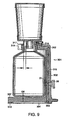
Figure 9 is a cross-sectional view, of another embodiment of a base according the present invention; -
Figure 10 is an isometric view, of another embodiment of a base according to the present invention; -
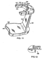
Figure 11 is an isometric view, of a base according to the present invention; -
Figure 12 is a partial cross-sectional view of an align pin of a receive receptacle adapted to mate with the a base; -
Figure 13 is an isometric view, having portions thereof removed, of the adapter component of the filtration device depicted inFigure 1 ; -
Figure 14 is a bottom isometric view of the adapter of the filtration device depicted inFigure 1 ; -
Figure 15 is an isometric view, having portions thereof removed, of an adapter component, not forming part of the claimed invention, including an integral receive receptacle; -
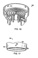
Figure 16 is an isometric view, having portions thereof removed, of another embodiment of an adapter; -
Figure 17 is a partial isometric view of the bottom portion of the receive receptacle depicted inFigure 16 , showing the funnel locking pins; and -
Figure 18 is a bottom isometric view, having portions thereof removed, of another embodiment of an adapter. - Illustrative embodiments relate to vacuum filtration systems and portions thereof, as well as methods for filtration.
- One embodiment of the present invention relates to a system that includes a filtering apparatus having receiving receptacle that is coupled to an adapter. The receiving receptacle receives a liquid to be filtered and may include a filtration element. The adapter is coupled between the receiving receptacle and an output receptacle that collects a filtered liquid. In addition, the system may include a base for supporting and directing a vacuum to the filtering apparatus.
- Of course, the present invention is not limited to the entire system and may include portions thereof, as well as methods for use. In one embodiment, the system may be utilized to filter a cell culture medium.
- One embodiment of a
filtration system 100 is shown inFigure 1 . Thesystem 100 includesfiltration apparatus 100a and abase 1 which both supports and directs a vacuum to thefiltration apparatus 100a. Thefiltration apparatus 100a may include anadapter 30 and receivingreceptacle 50. The receivingreceptacle 50 may receive an unfiltered liquid to be filtered, and may include afilter element 90. Thefiltration apparatus 100a may also include an output receptacle 80 (shown as a disposable centrifuge tube) and optionally alid 70. Of course, theoutput receptacle 80 may not be included in the system and the user may provide such a receptacle. Theoutput receptacle 80 may be a glass bottle, a test tube or any other satisfactory device for receiving a liquid. - The
output receptacle 80 may be releasably attached toadapter 30 viathreads 82 ofreceptacle 80. For instance, thethreads 82 may engage engaging threads 36 (Figure 13 ) of anadapter 30.Seal 35 of theadapter 30 seals the interior 81 ofoutput receptacle 80 toadapter 30 in a leak tight relationship. Theoutput receptacle 80 may be releasably attached to the adapter using other means, such as a press fit between theoutput receptacle 80 and theadapter 30. Likewise, other means could be used to seal theoutput receptacle 80 to theadapter 30, such as a gasket placed between the top surface of theoutput receptacle 80 and the corresponding surface of theadapter 30. -
Figure 2 shows one embodiment of the receivingreceptacle 50, which may include a filter element 90 (Figure 1 ) that serves to prevent un-filtered liquid from entering theoutlet 55 of receivingreceptacle 50. Thefilter element 90 may be a microporous filter element, or a depth filter element, and may be either hydrophilic or hydrophobic depending upon the liquid to be filtered. Representative filter element materials include, cellulose nitrate, cellulose acetate, mix esters of cellulose, Teflon, PVDF, Nylon, polypropylene, polyethylene, polycarbonate, and glass fibers, but are not limited to these materials. - The receiving
receptacle 50 receives a liquid to be filtered and may includeside wall 60,filter seal surface 51,baffle 54,outlet 55, and a filter support. In this embodiment, the filter support includesfilter support ribs 52 andchannels 61. The filter support provides the proper support forfilter element 90 and channels filtered liquid from the downstream side offilter element 90 intooutlet 55. Other types of filter supports that provide the proper support forfilter element 90 and that channels filtered liquid from the downstream side offilter element 90 intooutlet 55 could be used to replace the filter support shown inFigure 2 . - The outer periphery of the downstream side of the
filter element 90 may be sealed to filterseal surface 51, thereby preventing the flow of un-filtered liquid into theoutlet 55. Representative seals include a heat seal, an ultrasonic seal, a solvent seal, a glue seal, an RF seal, or a seal ring seal, or any other type of seal between any portion of the filter element and the funnel that prevents the flow of un-filtered liquid intooutlet 55.Side wall 60 includesinner surface 58,outer surface 56, and may includelid clamp ring 57. - Receiving
receptacle 50 may be non-releasably attached to theadapter 30 using an ultrasonic bond, a heat bond, a glue bond, a solvent bond, or any other type of leak tight bond, in which case the funnel and adapter are preferably made from the same materials, or of materials that can be easily bonded together. Materials may include acrylic, polycarbonate, styrene, polyethylene, and polypropylene. In applications where it is desired to releasably attach the receiving receptacle to the adapter, any of the releasable attachments disclosed in Patent No.6,913,152 could be used. Other types of releasable attachments could also be used. -
Figure 3 shows an illustrative embodiment of thelid 70, which may be type of lid releasably attached to receivingreceptacle 50 by any of the methods disclosed in Patent No.6,913,152 . Alternately other types of lids known in the art could also be used. - The
filtration apparatus 100a may also include aplug 48 as shown inFigure 1 , when the filtration device is to be used withbase 1. Theplug 48seals port 33a of theadapter 30. Alternately plug 48 may be replaced with a hose barb 45 (Figure 4 ) thereby allowingdisposable filtration device 100a to be used without thebase 1. Alternatively, theplug 48 could be integral part ofadapter 30. - Referring again to
Figure 1 , one embodiment of abase 1 is shown. As noted above, thebase 1 of this and other embodiments serves to support the filtration apparatus. In some embodiments the base supports the filtration apparatus in such a manner that theoutput receptacle 80 is suspended above the bottom portion 7 such that a gap G3 exists therebetween. - This embodiment includes an internal vacuum channel comprised of at least
conduit 2 and may also includeconduit 3 and terminates at adelivery port 2a. Thedelivery port 2a, when in operation, mates with theadapter 30 to create a seal so that a vacuum may be created in theoutput receptacle 80. - As shown in
Figure 1 , this embodiment of thebase 1 includes a bottom portion 7 and may also includehose barb 5,gasket 13, three-way valve 26, andseal 14. Theseal 14 is shown as an o-ring, but could be any type of seal such as a gasket or the like. - As shown in
Figure 5 , which is cut-away view of thebase 1 shown inFigure 1 , thebase 1 may include base support member 7,side wall 18, anddevice support member 19.Side wall 18 supportsdevice support member 19 so thatsupport surface 17 ofdevice support member 19 is located at the desired distance above the top of base support member 7.Side wall 18 preferably includes side wall relief 27 (i.e., the front and a portion of both sides ofside wall 18 are cut away) to make the receiving receptacle visible during the filtration cycle. - The
device support member 19 preferably includes at least one registration detail, such as analign pin 11, that is used to properly align the filtration device 101a on thebase 1. Thedevice support member 19 in conjunction with onealign pin 11, properly aligns the filtration device 101a on thebase 1. - The
base 1 also includes avacuum inlet 9, which is in fluid flow communication withconduit 2 andconduit 3.Conduit 3places vacuum inlet 9 in fluid flow communication withbase vacuum chamber 4, but may be omitted.Conduit 2 includes adelivery port 2a that places thevacuum inlet 9 in fluid flow communication withbottom inlet 34 of adapter 30 (Figure 13 ). - The
base 1 may be made of a substantially rigid material and theconduits base 1. Thedelivery port 2a may be referred to herein as a "base vacuum delivery port". - In
Figures 5 and 6 , thebase 1 may also include a valve hole 6, which in turn forms avent slot 8 containing a three-way valve may be used. As shown inFigure 6 , three-way valve 26 includesvacuum port 21, ventport 22, snapfit tabs 23, and handle 25. Three-way valve 26 snaps into valve hole 6 ofbase 1 as shown inFigure 1 . In alternative embodiments, the three-way valve 26 may be attached tobase 1 by other than the snap fit tabs disclosed herein. As an example,Figure 7 shows the three-way valve 26 in the open position withvacuum port 21 connecting the top and bottom portions ofconduit 2, and withvent port 22 blocked off by the side wall of valve hole 6 that does not includevent slot 8.Figure 8 shows the three-way valve 26 in the closed position withvent port 22 andvacuum port 21 in fluid communication withvent slot 8. - Among other things, the
base 1 may be cast or machined from materials, such as urethane, or epoxy, or could be either cast or machined from materials, such as stainless steel or aluminum, or molded or machined from plastics such as polycarbonate, acrylic, or polysulfone. - Another embodiment of a
base 301 and a receiving receptacle 380 (i.e., a bottle) is shown inFigure 9 . Thebase 301 of this embodiment includes alower portion 307, agasket 313, three-way valve 26, and seal 314 shown as an o-ring, but could be any type of seal, such as a gasket. Thebase 301 includes aside wall 318 havingvacuum channel 302 disposal therein anddevice support member 319, and integral hose barb 305.Side wall 318 supportsdevice support member 319 so thatsupport surface 317 ofdevice support member 319 is located at the desired distance above thelower portion 307. Thedevice support member 319 may include one or more registration details, such as align pins, to properly align the disposable filtration device on the base. - Another embodiment of a base is shown in
Figure 10 . The base 401 portions similar to the previous embodiments and includes one or more align pins 411, that are used to properly align the filtration device on the base. - Another embodiment of a base is shown in
Figure 11 . Thebase 501 of this embodiment includesbase support member 520,side wall 543, anddevice support member 519. Theside wall 543 supportsdevice support member 519 so thatsupport surface 517 ofdevice support member 519 is located at the desired distance above the top 529 ofbase support member 520. Thedevice support member 519 may include at least registration details 511 (two registration details are shown inFigure 11 ) that are used to align and lock in place the disposable filtration device on thebase 501. For instance, theregistration detail 511 could mate with acorresponding registration detail 537 of theadapter 550 shown inFigure 12 . - In addition to the registration details, the
base 501 may also include a well 516 defined bysupport surface 517 andside wall 515. The shape ofside wall 515 may be designed so that it matches the shape of the flange on an adapter of any of the adapter embodiments described herein. In addition, this embodiment includes an internal vacuum chamber (not shown) that terminates at the basevacuum delivery port 502a. -
Figures 13 and 14 show one example of anadapter 30 according to the present invention. Theadapter 30 of this embodiment may include aflange 38,side inlet 33,bottom inlet 34,seal 35, andthreads 36.Flange 38 includestop surface 41,bottom surface 39, and at least onealign slot 37. Theadapter 30 may also include either plug 48 (Figure 1 ) or hose barb 45 (Figure 4 ), and may also include a filter element located insideinlet 33. In the event theside inlet 33 is filled with a hose barb, the filtering system may be used without abase 1 as thebottom inlet 34 is filled by the hose barb. - The
flange 38 may define the outer periphery of theadapter 30. Thebottom surface 39 of theflange 38 includes abottom inlet 34. When in use, thebottom inlet 34 is aligned with the basevacuum delivery port 2a of any of the embodiments of the base disclosed herein. The alignment of thebottom inlet 34 with a base vacuum delivery port serves to create a vacuum in theoutput receptacle 80 when a vacuum is applied to the internal vacuum channel of the base. - The
seal 35 seals the interior of an output receptacle attached to theadapter 30 in a leak tight relationship. In some embodiments, the adapter may includethreads 36 to mate with corresponding threads on an output receptacle. - The
adapter 30 may also include acenter hole 40 through which fluid will pass when in operation. Theadapter 30 may also include side wall 44 that hasinner surface 31 andstep 32. Thestep 32 may support a receivingreceptacle 50 when coupled to theadapter 30. - The
flange 38 may also include aregistration detail 37. Theregistration detail 37 is shown as a slot but could be any detail capable of ensuring that thebottom inlet 34 is aligned over the basevacuum outlet port 2a when theadapter 30 is coupled to a base. In one embodiment, the registration detail may require that theadapter 30 only be coupled to the base in one particular orientation (i.e., alignment of the two noted parts) and may, in some embodiments, guide the adapter to that particular orientation. In some embodiments, the base may have a corresponding registration detail to mate with theregistration detail 37 of theadapter 30. Of course, theadapter 30 could have more than one registration detail. Examples of other types of registration details that could be included in theadapter 30 include, but are not limited to, a protrusion, a recess, a pin, a slot, and the like. In some embodiments the registration details may serve to automatically connect thebottom inlet 34 with the basevacuum outlet port 2a. In some embodiments this may advantageously allow a user to place thefiltration device 100a on thebase 1 with 1 hand. - Of course, the
adapter 30 could be modified depending on the application. For example, and as shown inFigure 15 , theadapter 230 may include aflange 238,side inlet 233,threads 236, and anintegral receiving receptacle 258. In this embodiment, theflange 238 may also include one or more registration details 237. Theintegral receiving receptacle 258 includes aside wall 260, filterseal surface 251,baffle 254,outlet 255, and a filter support. The filter support includesfilter support ribs 252 andchannels 261, and at least oneradial channel 253. The filter support provides the proper support for a filter element 90 (not shown) and channels filtered liquid from the downstream side offilter element 90 intooutlet 255. Any type of filter that provides the proper support forfilter element 90, and channels filtered liquid from the downstream side offilter element 90 intooutlet 255 could be used to replace the filter support means shown inFigure 15 . The outer periphery of the downstream side offilter element 90 may be sealed to filterseal surface 251, thereby preventing the flow of un-filtered liquid into theoutlet 255. - Another embodiment of an adapter is shown in
Figure 16 . Theadapter 330 in this embodiment, unlike the previous embodiment, does not have an integral receive receptacle but, rather, includes aside wall 344 having one ormore slots 343. The receivingreceptacle 350 shown inFigure 17 may includecomplementary protrusion 365 in itssidewall 356 to lock the receive receptacle into theadapter 330. - In another embodiment, and as shown in
Figure 18 , theadapter 430 does not include aflange 38. In this embodiment, theadapter 430 includes aside wall 444 having aninner surface 431 and at least oneslot 443. One or more align rings 469 extend from a lower surface 475 ofadapter 430. These align rings are designed to mate, for example, with thepins 411 on the base 401 shown inFigure 10 . The bottom of side wall 434a ofbottom inlet 434 may include a spherical surface 447 which may mate with the basevacuum delivery port 476 of the base 401 shown inFigure 10 . - Various embodiments of the present invention and portions thereof have been described above. In general the systems described herein may operate as follows with reference to
Figure 1 . - The end user may provide the
filtration device 100a by either purchasing a complete assembly or an assembly without anoutput receptacle 81, in which case the user will attach an output receptacle (preferably pre-sterilized) to theadapter 30. The user then places thebase 1 on a flat surface and connects a vacuum hose thereto, for example, viahose barb 5. The other end of the vacuum hose may be connected to a vacuum source. - If a three
way valve 26 is present, it initially may be turned to the off position. The user may start a vacuum source to evaluatebase vacuum chamber 4 of the lower portion 7 of thebase 1 to hold thebase 1 in place. Of course,vacuum chamber 4 could be omitted and this step skipped. - The user then may place the
filtration device 100a with a output receptacle 80 (attached to adapter 30), ontoreusable base 1, by insertingreceptacle 80 into hole 10 (Figure 5 ) ofbase 1 untilbottom surface 39 offlange 38 ofadapter 30 contacts supportsurface 17 ofbase 1. The user adjusts the orientation until there is a registration fit with align pin 11 (Figure 5 ) ofbase 1 and align slot 37 (Figure 13 ) ofadapter 30. This alignment aligns thebottom inlet 34 ofadapter 30 with base vacuumchannel output port 2a ofconduit 2. Of course, in this and other embodiments thealign pin 11 and thealign slot 57 could be eliminated and the user could manually align the filtration device 101a so thatinlet 34 aligns withport 2a. - When
filtration device 100a is properly positioned onbase 1 as shown inFigure 1 , a gap G3 will exist between the bottom ofreceptacle 80 and the bottom portion 7 of thebase 1. Of course the gap G3 could also be between the bottom of thereceptacle 80 and the surface on which thebase 1 sets. When spaced in this manner, the receptacle 80 (andfiltering apparatus 100a) is considered to be suspended by the base. - As shown in
Figure 1 , the supportupper surface 17 of the support is arranged so that it is upstream of the receivingreceptacle 80. As used herein, upsteam means a location above another location in a direction opposite to that in which a fluid would flow if orientated as shown. Here, upstream means that the support is above the output receptacle in the "Y" direction. - During actual use, a user may remove the
lid 70 from receivingreceptacle 50, and pour quantity of un-filtered liquid (such as cell culture media) may be added to the interior of receivingreceptacle 50, upstream offilter element 90. Thelid 70 may then be re-attached to receivingreceptacle 50 as shown inFigure 1 . The user then simply turns three-way valve to the on position shown inFigure 1 , thereby evacuating the interior 81 ofreceptacle 80. If the inside surface area of theseal 14 is larger than the cross-sectional area ofbottom inlet 34 ofadapter 30 as shown inFigure 1 , the vacuum at basevacuum outlet port 2a ofconduit 2 ofbase 1 will create a downward force on the surface area ofbottom surface 39 offlange 38 ofadapter 30 that is encircled byseal 14, thereby creating a downward force on said area and firmly holdingdisposable filtration apparatus 100a in place onbase 1. - The initial air in the
interior 81 ofreceptacle 80, and in the filter support means of receivereceptacle 50, will flow from the interior ofoutput receptacle 80; through gap G1 betweeninner surface 42 ofadapter 30 and outer surface 63 of baffle 54 (Figure 2 ); intoside inlet 33 ofadapter 30; through filter element 49 (iffilter element 49 is used); throughbottom inlet 34; intoinlet 2a ofconduit 2, throughconduit 2; throughvacuum inlet 9 of thebase 1; and into the vacuum source. - The top surface of the un-filtered liquid in receive
receptacle 50 will be kept at atmospheric pressure via a venting means in either the receive receptacle or thelid 70. Therefore the positive pressure of the liquid at the level of the upstream surface offilter element 90 will be proportional to the height of the liquid in the receive receptacle. Therefore, a differential pressure will exist between the positive pressure of the liquid on the upstream side of the filter element and the negative pressure on the downstream side of the filter element, created by evacuating the interior of the receptacle. As the interior ofreceptacle 80 is evacuated, un-filtered liquid from receivereceptacle 50 will pass throughfilter element 90. The filtered liquid on the downstream side offilter element 90 will then pass throughoutlet 55 of receivereceptacle 50, intooutput receptacle 80. This process will continue until all of the un-filtered liquid has been filtered and collected inoutput receptacle 80. - After all of the liquid has been filtered and collected in
output receptacle 80, the user may turn three-way valve 26 to the closed position and, thus, vent to atmosphere the interior ofoutput receptacle 80, the upper part ofconduit 2,bottom inlet 34,side inlet 33, and the filter support of the receivereceptacle 50, by allowing external air to entervent slot 8 of base 1 (Figure 5 ); and then pass throughvacuum port 21 and ventport 22 of three-way valve 26 (Figure 6 ); through the upper portion ofconduit 2 ofbase 2; throughbottom inlet 34, andside inlet 33 ofadapter 30; throughfilter element 49; into the interior ofoutput receptacle 80. - In some embodiments,
optional filter element 49 may prevent non-sterile air from entering the interior ofoutput receptacle 80. The user may then removedisposable filtration device 100a from thebase 1 and then remove the output receptacle fromadapter 30, attach a closure to the top of output receptacle 80 (closure not shown), and discard the remaining components ofdisposable filtration device 100a in a safe manner. The receptacle along with its contents can now be either used or stored. If three-way valve 26 is not used, then the vacuum would be turned on, and turned off, and vented externally to the reusable base. - Although the present invention has been shown and described in terms of specific preferred embodiments, it will be appreciated by those skilled in the art that changes or modifications are possible which do not depart from the scope of the invention as defined by the appended claims.
Claims (15)
- A liquid filtering system (100) comprising:a filtering apparatus (100a) having a receiving receptacle (50;350) coupled with an adapter (30; 330; 430) having an adapter port (34) for receiving a vacuum, the adapter also having an interface (36) for coupling with an output receptacle (80) for receiving filtered liquid from the filtering apparatus, the adapter being between the receiving receptacle and output receptacle when the output receptacle is coupled with the adapter interface;a base (1; 301; 401; 501) having a substantially rigid housing containing an internal vacuum channel (2; 302; 402) terminating at a base vacuum delivery port (2a; 502a), the base also having a support (19; 319; 419; 519) for supporting the filtering apparatus, characterized in that:the adapter is couplable with the base to support the filtering apparatus and to connect the adapter port to the base vacuum delivery port.
- The system as defined by claim 1 wherein the filtering apparatus also comprises a cell culture medium filter (90) for filtering a liquid received by the receiving receptacle.
- The system as defined by claim 1 further comprising the output receptacle coupled with the adapter interface, preferably wherein the output receptacle comprises threads (82) that mate with corresponding threads in the interface.
- The system as defined by claim 1 wherein the filtering apparatus is removably couplable with the base, preferably further comprising:the output receptacle coupled with the adapter interface, the base having a bottom portion (7), the base suspending the output receptacle above the bottom portion to form a gap (G3) therebetween.
- The system as defined by claim 1 further comprising a seal (14) to provide a sealed connection between the adapter port and the vacuum delivery port of the base.
- The system as defined by claim 1 wherein the filtering apparatus and base are configured to provide a registration coupling in a manner that connects the base vacuum delivery port with the adapter port, preferably wherein:the filtering apparatus has a first aligning detail (37), the base having a second aligning detail (11; 411), the first and second aligning details being in registry when the base is coupled with the adapter to align the base vacuum delivery port with the adapter port.
- The system as defined by claim 1 wherein the base has a vacuum receiving port (9) for receiving a vacuum from an external source, the internal vacuum channel being between the vacuum receive port and the base vacuum delivery port.
- The system as defined by claim 1 wherein the receiving receptacle comprises a funnel.
- A method of filtering a liquid sample, the method comprising:providing a a liquid filtering system (100) according to claim 1coupling the adapter of the filtering apparatus to a portion of the base thereby supporting the filtering apparatus, the filtering apparatus oriented on the base such that the adapter port is in fluid communication with the vacuum channel in the base;applying a vacuum to the interior of the output receptacle through the vacuum channel and the filtering apparatus;pouring the liquid sample into the filtering apparatus;permitting the liquid sample to pass through the filtering apparatus to the output receptacle downstream of the portion of the base coupled with the filtering apparatus;removing the output receptacle from the filtering apparatus; anduncoupling the filtering apparatus from the base.
- The method as defined by claim 9 wherein the filtering apparatus fits in registry with corresponding registration details (11; 411) on the base.
- The method as defined by claim 10 wherein the filtering apparatus is substantially removably locked in position when in registration with the base.
- The method as defined by claim 9 further comprising discarding the filtering apparatus. ,
- The method as defined by claim 9 further comprising sealing the receiving receptacle.
- The method as defined by claim 9 wherein the receiving receptacle is suspended when the filtering apparatus is coupled with the base.
- The method as defined by claim 9 wherein the liquid sample is a cell culture medium.
Applications Claiming Priority (2)
| Application Number | Priority Date | Filing Date | Title |
|---|---|---|---|
| US71401705P | 2005-09-02 | 2005-09-02 | |
| PCT/US2006/034560 WO2007028157A1 (en) | 2005-09-02 | 2006-09-05 | Systems, apparatus and methods for vacuum filtration |
Publications (2)
| Publication Number | Publication Date |
|---|---|
| EP1919622A1 EP1919622A1 (en) | 2008-05-14 |
| EP1919622B1 true EP1919622B1 (en) | 2013-08-14 |
Family
ID=37561162
Family Applications (1)
| Application Number | Title | Priority Date | Filing Date |
|---|---|---|---|
| EP06802979.2A Not-in-force EP1919622B1 (en) | 2005-09-02 | 2006-09-05 | Systems, apparatus and methods for vacuum filtration |
Country Status (5)
| Country | Link |
|---|---|
| US (2) | US7798333B2 (en) |
| EP (1) | EP1919622B1 (en) |
| JP (1) | JP2009506886A (en) |
| CN (1) | CN101312785B (en) |
| WO (1) | WO2007028157A1 (en) |
Cited By (1)
| Publication number | Priority date | Publication date | Assignee | Title |
|---|---|---|---|---|
| RU217761U1 (en) * | 2023-01-24 | 2023-04-17 | Федеральное государственное бюджетное учреждение "Институт глобального климата и экологии имени академика Ю.А. Израэля" | Vacuum Filtration Device |
Families Citing this family (39)
| Publication number | Priority date | Publication date | Assignee | Title |
|---|---|---|---|---|
| US7798333B2 (en) * | 2005-09-02 | 2010-09-21 | Roush Life Sciences, Llc | Systems, apparatus and methods for vacuum filtration |
| WO2008144083A1 (en) * | 2007-05-23 | 2008-11-27 | Nypro Inc. | Methods and apparatus for foam control in a vacuum filtration system |
| US8231012B2 (en) * | 2007-07-26 | 2012-07-31 | Roush Life Sciences, Llc | Filtrate storage system |
| WO2009014769A1 (en) | 2007-07-26 | 2009-01-29 | Nypro Inc. | Methods and apparatus for supporting a vacuum filtration device |
| US8863594B2 (en) * | 2008-02-22 | 2014-10-21 | Foxx Life Sciences | Sample container and filtration apparatus and method of filtration using same |
| US20090215150A1 (en) * | 2008-02-22 | 2009-08-27 | Jeffrey Kane | Sample container and filtration apparatus and method of filtration using the same |
| USD795437S1 (en) | 2008-08-14 | 2017-08-22 | Chemrus Inc. | Disposable polymer-structured filter |
| US8978897B2 (en) * | 2008-08-14 | 2015-03-17 | Chemrus Inc. | Disposable polymer-structured filtering kit |
| US20100051562A1 (en) * | 2008-08-28 | 2010-03-04 | Tyler Jameson Coleman | Funnel with reusable filter media for liquids |
| WO2010101865A1 (en) * | 2009-03-02 | 2010-09-10 | Zymo Research Corporation | Universal column |
| USD782681S1 (en) | 2009-08-12 | 2017-03-28 | Chemrus Inc. | Disposable polymer-structured filter |
| CN102781537B (en) * | 2010-02-17 | 2015-08-26 | 蔡健健 | Disposable macromolecular filtering funnel device |
| US8808552B2 (en) * | 2010-12-16 | 2014-08-19 | Zenpure (Hangzhou) Co., Ltd. | Stackable filter cup apparatus and method |
| JP5801958B2 (en) | 2011-06-27 | 2015-10-28 | イー・エム・デイー・ミリポア・コーポレイシヨン | Method and apparatus for filtering a liquid sample |
| CN103091147A (en) * | 2011-10-28 | 2013-05-08 | 中国科学院海洋研究所 | Automated multilevel biological sample filtering system |
| JP6482459B2 (en) | 2012-05-02 | 2019-03-13 | チャールズ リバー ラボラトリーズ, インコーポレイテッド | Method for detecting viable cells in a cell sample |
| DE102012015063B4 (en) * | 2012-07-31 | 2014-10-30 | Sartorius Stedim Biotech Gmbh | Apparatus and method for treating a filtration medium |
| US9841360B1 (en) * | 2012-10-15 | 2017-12-12 | Michael C. Solazzi | Sample cup assembly, system and method for purging |
| USD704383S1 (en) * | 2013-02-07 | 2014-05-06 | Anna M. Edlin | Pet travel cup with internal spiral member and rimmed edge |
| US10302534B2 (en) | 2013-09-05 | 2019-05-28 | Merck Patent Gmbh | Filter device for filtering complex fluid samples |
| JP6556155B2 (en) * | 2013-11-04 | 2019-08-07 | チャールズ リバー ラボラトリーズ, インコーポレイテッド | Filtration system and its use |
| US10278534B2 (en) * | 2013-12-01 | 2019-05-07 | Fellow Industries Inc. | Beverage steeping and dispensing system |
| EP3291918B1 (en) * | 2015-05-05 | 2019-04-17 | Mallinckrodt Hospital Products IP Limited | Support for centrifuge tubing |
| US11305291B2 (en) | 2016-02-18 | 2022-04-19 | Siemens Healthcare Diagnostics Inc. | Rack for a filtration device |
| WO2017143306A1 (en) * | 2016-02-18 | 2017-08-24 | Siemens Healthcare Diagnostics Inc. | Container for a filtration assembly |
| US10981119B2 (en) | 2016-02-18 | 2021-04-20 | Siemens Healthcare Diagnostics Inc. | Gas in/outlet adapter system for a filtration device |
| EP3452254B1 (en) | 2016-05-05 | 2023-04-19 | EMD Millipore Corporation | Filtration clamp with optional alignment collar and filtration system |
| USD792971S1 (en) * | 2016-05-05 | 2017-07-25 | Emd Millipore Corporation | Clamp |
| US11623215B2 (en) | 2017-05-10 | 2023-04-11 | Emd Millipore Corporation | Multiwell plate with variable compression seal |
| WO2018224999A1 (en) * | 2017-06-08 | 2018-12-13 | Gupta Nalini K | A filter assembly |
| US11325117B2 (en) * | 2017-07-27 | 2022-05-10 | Biomerieux, Inc. | Centrifugally separating samples in a container having a seal and containing a plunger for opening the seal |
| DE102017127969B3 (en) | 2017-11-27 | 2019-01-17 | Sartorius Stedim Biotech Gmbh | Connecting device for a suction device |
| KR102071046B1 (en) * | 2018-02-05 | 2020-01-28 | 주식회사 이노디자인 | Dripper and portable coffee drinking tumbler |
| WO2019181106A1 (en) * | 2018-03-19 | 2019-09-26 | 株式会社村田製作所 | Filtration device |
| EP3593903B1 (en) * | 2018-07-10 | 2020-09-02 | Sartorius Stedim Biotech GmbH | Liquid filtering system with vacuum valve |
| WO2020028196A1 (en) * | 2018-07-28 | 2020-02-06 | Leavitt Medical, Inc. | Methods and systems for preparing cytological samples |
| US11724057B2 (en) | 2019-12-16 | 2023-08-15 | Melissa H. Egts | Protective, sanitary, securable nasal cannula cover |
| USD942002S1 (en) | 2019-12-16 | 2022-01-25 | Melissa H. Egts | Nasal cannula cover |
| WO2023007224A1 (en) * | 2021-07-29 | 2023-02-02 | Ecole Polytechnique Federale De Lausanne (Epfl) | Biological material pooling device for biological or biomolecule purification |
Family Cites Families (63)
| Publication number | Priority date | Publication date | Assignee | Title |
|---|---|---|---|---|
| US1168988A (en) * | 1914-08-05 | 1916-01-18 | Arthur Zimmermann | Percolator. |
| US1216112A (en) | 1916-11-08 | 1917-02-13 | Derk Greven | Strainer for liquids. |
| US1501073A (en) | 1922-04-17 | 1924-07-15 | Stead Aquila Moore | Funnel strainer |
| US2460423A (en) | 1945-03-26 | 1949-02-01 | Sparkler Mfg Co | Filter |
| US2608843A (en) * | 1946-04-19 | 1952-09-02 | John J Kennedy | Rack with drip catcher |
| US2584206A (en) | 1949-04-07 | 1952-02-05 | Int Harvester Co | Milk strainer |
| US2818178A (en) | 1954-04-13 | 1957-12-31 | Int Harvester Co | Milk strainer for parlor milkers |
| US3010583A (en) | 1959-10-23 | 1961-11-28 | Millipore Filter Corp | Fluid sampling device |
| US3319792A (en) * | 1964-10-19 | 1967-05-16 | Leder Philip | Multiple filtration apparatus |
| US3469369A (en) | 1966-12-29 | 1969-09-30 | Bell Telephone Labor Inc | Method for preparing and applying a viscous fluid |
| US3478889A (en) | 1967-08-31 | 1969-11-18 | Julius H Fessler | Filter apparatus |
| US3752651A (en) * | 1971-04-15 | 1973-08-14 | Cybertek Inc | Method and apparatus for extraction of solvent extracts |
| US3730352A (en) | 1971-12-06 | 1973-05-01 | New Brunswick Scientific Co | Filtration apparatus |
| US3838978A (en) | 1972-08-17 | 1974-10-01 | Bio Spectrum Inc | Vacuum filter with removable filter element |
| GB1467428A (en) | 1973-08-17 | 1977-03-16 | Strutt Farrands Ltd | Filtration apparauts |
| DE2526295B2 (en) | 1975-06-12 | 1978-11-23 | Hoechst Ag, 6000 Frankfurt | Method of manufacturing a nutsche |
| US4247399A (en) | 1979-03-12 | 1981-01-27 | Isadore Pitesky | Filtering and particulate washing device |
| US4251366A (en) * | 1979-06-18 | 1981-02-17 | Simon Timothy M | Adapter for laboratory filter |
| US4301010A (en) | 1980-03-10 | 1981-11-17 | Spectrum Medical Industries, Inc. | Vacuum filter |
| US4357240A (en) | 1981-02-27 | 1982-11-02 | Sybron Corporation | Disposable, one-piece filter unit |
| US4614585A (en) | 1981-03-02 | 1986-09-30 | Sybron Corporation | Frangible bonded disposable filtration unit with recoverable filter |
| US4678576A (en) | 1981-09-16 | 1987-07-07 | Nalge Company | Reusable filter unit with recoverable filter membrane |
| US4394266A (en) | 1981-11-16 | 1983-07-19 | Sybron Corporation | Pressure filter adapter and containment vessel |
| US4521308A (en) * | 1982-08-13 | 1985-06-04 | The Regents Of The University Of California | Rotary support for vacuum filtration apparatus |
| DE3405105C1 (en) | 1984-02-14 | 1985-04-25 | Karl 7298 Loßburg Hehl | Oil container of a plastic injection molding machine with an air filter on a pressure compensation opening |
| US4523934A (en) | 1984-03-06 | 1985-06-18 | Henry Joshua | Filter-degasser |
| US4689147A (en) | 1985-09-27 | 1987-08-25 | Nalge Company | Plastic filter assembly |
| USD297860S (en) | 1985-10-18 | 1988-09-27 | Nalge Company | Filter unit |
| US4673501A (en) | 1985-11-19 | 1987-06-16 | Miles Laboratories, Inc. | Bottle top filter |
| US4702834A (en) | 1986-06-17 | 1987-10-27 | Nalge Company | Plastic filter units having a weld cellulose filter |
| US4792398A (en) | 1987-08-10 | 1988-12-20 | Marion Laboratories, Inc. | Manual vacuum filtration device |
| US4783318A (en) | 1987-10-02 | 1988-11-08 | The State Of Minnesota | Apparatus for environmental leaching testing |
| US4894155A (en) | 1988-04-14 | 1990-01-16 | Nalge Cmpany | Single membrane disc supporting upper and lower membranes |
| US4944876A (en) | 1989-10-03 | 1990-07-31 | Telectro-Mek, Inc. | Filter capsule with inlet dispersion |
| US5141639A (en) | 1990-08-14 | 1992-08-25 | Gelman Sciences, Inc. | Vacuum filter assembly |
| US5112484A (en) | 1990-10-11 | 1992-05-12 | Zuk, Inc. | Filtration apparatus |
| GB2250927A (en) | 1990-12-19 | 1992-06-24 | Lam Kwok Tai | Suction filter |
| US5264184A (en) | 1991-03-19 | 1993-11-23 | Minnesota Mining And Manufacturing Company | Device and a method for separating liquid samples |
| US5116496A (en) | 1991-03-19 | 1992-05-26 | Minnesota Mining And Manufacturing Company | Membrane-containing wells for microtitration and microfiltration |
| US5227137A (en) | 1991-04-04 | 1993-07-13 | Nicholson Precision Instruments Inc. | Vacuum clamped multi-sample filtration apparatus |
| US5205989A (en) | 1991-09-18 | 1993-04-27 | Minnesota Mining And Manufacturing Company | Multi-well filtration apparatus |
| US5234585A (en) | 1991-12-19 | 1993-08-10 | Zuk, Incorporated | Vacuum filtration device |
| US5948246A (en) * | 1991-12-19 | 1999-09-07 | Zuk, Jr.; Peter | Vacuum filtration device |
| US5308483A (en) | 1992-08-27 | 1994-05-03 | Gelman Sciences Inc. | Microporous filtration funnel assembly |
| US5375477A (en) | 1993-01-04 | 1994-12-27 | S.P. Industries, Limited Partnership | Water impurity extraction device and method |
| CN2148598Y (en) * | 1993-02-27 | 1993-12-08 | 彭炎春 | Fast-acting microporous filter diaphragm filtrator series |
| US5603900A (en) | 1995-05-19 | 1997-02-18 | Millipore Investment Holdings Limited | Vacuum filter device |
| JP3586531B2 (en) * | 1997-02-05 | 2004-11-10 | 武藤化学株式会社 | Specimen preparation equipment using a filter with filter |
| US5785927A (en) | 1996-10-24 | 1998-07-28 | Eli Lilly And Company | Vessel handling system useful for combinatorial chemistry |
| DE69833185T2 (en) | 1997-01-29 | 2006-08-10 | Pall Corp. | FILTRATION ARRANGEMENT |
| US6159368A (en) | 1998-10-29 | 2000-12-12 | The Perkin-Elmer Corporation | Multi-well microfiltration apparatus |
| US6419827B1 (en) | 1998-10-29 | 2002-07-16 | Applera Corporation | Purification apparatus and method |
| US6379625B1 (en) | 1999-12-23 | 2002-04-30 | Peter Zuk, Jr. | Apparatus comprising a disposable device and reusable instrument for synthesizing chemical compounds, and for testing chemical compounds for solubility |
| US6951762B2 (en) | 1998-12-23 | 2005-10-04 | Zuk Jr Peter | Apparatus comprising a disposable device and reusable instrument for synthesizing chemical compounds, and for testing chemical compounds for solubility |
| US6458278B1 (en) | 1999-02-22 | 2002-10-01 | Nalge Nunc International Corporation | Filtering unit having separately attachable filter cassette, filter cassette, and method of filtering |
| CA2337987A1 (en) | 2000-02-25 | 2001-08-25 | Elmex Limited | Membrane filtration system |
| US20020096468A1 (en) | 2000-12-04 | 2002-07-25 | Peter Zuk | Disposable vacuum filtration apparatus capable of detecting microorganisms and particulates in liquid samples |
| US6913152B2 (en) | 2000-12-04 | 2005-07-05 | Peter Zuk, Jr. | Disposable vacuum filtration apparatus capable of detecting microorganisms and particulates in liquid samples |
| US6491873B2 (en) * | 2001-01-23 | 2002-12-10 | Varian, Inc. | Multi-well filtration apparatus |
| US7011755B2 (en) | 2001-05-31 | 2006-03-14 | Zuk Jr Peter | Disposable vacuum filtration funnel with integral prefilter |
| US6986849B2 (en) | 2003-04-14 | 2006-01-17 | Irvine William O | Liquid/solid separator and method |
| US7240572B2 (en) * | 2004-02-18 | 2007-07-10 | Millipore Corporation | Vacuum assisted affinity chromatography device and method |
| US7798333B2 (en) * | 2005-09-02 | 2010-09-21 | Roush Life Sciences, Llc | Systems, apparatus and methods for vacuum filtration |
-
2006
- 2006-09-05 US US11/516,011 patent/US7798333B2/en active Active
- 2006-09-05 JP JP2008529371A patent/JP2009506886A/en active Pending
- 2006-09-05 CN CN2006800322189A patent/CN101312785B/en active Active
- 2006-09-05 WO PCT/US2006/034560 patent/WO2007028157A1/en active Application Filing
- 2006-09-05 EP EP06802979.2A patent/EP1919622B1/en not_active Not-in-force
-
2010
- 2010-08-26 US US12/869,047 patent/US20100320134A1/en not_active Abandoned
Cited By (1)
| Publication number | Priority date | Publication date | Assignee | Title |
|---|---|---|---|---|
| RU217761U1 (en) * | 2023-01-24 | 2023-04-17 | Федеральное государственное бюджетное учреждение "Институт глобального климата и экологии имени академика Ю.А. Израэля" | Vacuum Filtration Device |
Also Published As
| Publication number | Publication date |
|---|---|
| US7798333B2 (en) | 2010-09-21 |
| WO2007028157A1 (en) | 2007-03-08 |
| JP2009506886A (en) | 2009-02-19 |
| EP1919622A1 (en) | 2008-05-14 |
| US20070144959A1 (en) | 2007-06-28 |
| CN101312785B (en) | 2011-03-30 |
| CN101312785A (en) | 2008-11-26 |
| US20100320134A1 (en) | 2010-12-23 |
Similar Documents
| Publication | Publication Date | Title |
|---|---|---|
| EP1919622B1 (en) | Systems, apparatus and methods for vacuum filtration | |
| JP2009506886A5 (en) | ||
| US20210001249A1 (en) | Disposable polymer-structured filter | |
| EP1074292B1 (en) | Vacuum filter device | |
| EP3448450B1 (en) | Fluid collection systems and methods of use | |
| US5308483A (en) | Microporous filtration funnel assembly | |
| JP5432891B2 (en) | Duplex container and dispensing method | |
| JPH08502449A (en) | Vacuum filtration device | |
| GB2323288A (en) | Apparatus for separating tissue from aspirates | |
| KR20010085619A (en) | Membrane filter system | |
| CN111065446B (en) | Filter assembly and method for microbiological testing | |
| JP2012149636A (en) | Peristaltic pump and filtration assembly system for use therewith | |
| US20040063169A1 (en) | Filtration assembly | |
| EP2523739B1 (en) | Disposable polymer-structured filtering kit | |
| EP1383861B1 (en) | Filtration assembly |
Legal Events
| Date | Code | Title | Description |
|---|---|---|---|
| PUAI | Public reference made under article 153(3) epc to a published international application that has entered the european phase |
Free format text: ORIGINAL CODE: 0009012 |
|
| 17P | Request for examination filed |
Effective date: 20080221 |
|
| AK | Designated contracting states |
Kind code of ref document: A1 Designated state(s): AT BE BG CH CY CZ DE DK EE ES FI FR GB GR HU IE IS IT LI LT LU LV MC NL PL PT RO SE SI SK TR |
|
| 17Q | First examination report despatched |
Effective date: 20110307 |
|
| DAX | Request for extension of the european patent (deleted) | ||
| GRAP | Despatch of communication of intention to grant a patent |
Free format text: ORIGINAL CODE: EPIDOSNIGR1 |
|
| GRAS | Grant fee paid |
Free format text: ORIGINAL CODE: EPIDOSNIGR3 |
|
| GRAA | (expected) grant |
Free format text: ORIGINAL CODE: 0009210 |
|
| AK | Designated contracting states |
Kind code of ref document: B1 Designated state(s): AT BE BG CH CY CZ DE DK EE ES FI FR GB GR HU IE IS IT LI LT LU LV MC NL PL PT RO SE SI SK TR |
|
| REG | Reference to a national code |
Ref country code: GB Ref legal event code: FG4D |
|
| REG | Reference to a national code |
Ref country code: CH Ref legal event code: EP Ref country code: AT Ref legal event code: REF Ref document number: 626465 Country of ref document: AT Kind code of ref document: T Effective date: 20130815 |
|
| REG | Reference to a national code |
Ref country code: IE Ref legal event code: FG4D |
|
| REG | Reference to a national code |
Ref country code: DE Ref legal event code: R096 Ref document number: 602006037866 Country of ref document: DE Effective date: 20131010 |
|
| REG | Reference to a national code |
Ref country code: AT Ref legal event code: MK05 Ref document number: 626465 Country of ref document: AT Kind code of ref document: T Effective date: 20130814 Ref country code: NL Ref legal event code: VDEP Effective date: 20130814 |
|
| REG | Reference to a national code |
Ref country code: LT Ref legal event code: MG4D |
|
| PG25 | Lapsed in a contracting state [announced via postgrant information from national office to epo] |
Ref country code: SE Free format text: LAPSE BECAUSE OF FAILURE TO SUBMIT A TRANSLATION OF THE DESCRIPTION OR TO PAY THE FEE WITHIN THE PRESCRIBED TIME-LIMIT Effective date: 20130814 Ref country code: LT Free format text: LAPSE BECAUSE OF FAILURE TO SUBMIT A TRANSLATION OF THE DESCRIPTION OR TO PAY THE FEE WITHIN THE PRESCRIBED TIME-LIMIT Effective date: 20130814 Ref country code: IS Free format text: LAPSE BECAUSE OF FAILURE TO SUBMIT A TRANSLATION OF THE DESCRIPTION OR TO PAY THE FEE WITHIN THE PRESCRIBED TIME-LIMIT Effective date: 20131214 Ref country code: AT Free format text: LAPSE BECAUSE OF FAILURE TO SUBMIT A TRANSLATION OF THE DESCRIPTION OR TO PAY THE FEE WITHIN THE PRESCRIBED TIME-LIMIT Effective date: 20130814 Ref country code: CY Free format text: LAPSE BECAUSE OF FAILURE TO SUBMIT A TRANSLATION OF THE DESCRIPTION OR TO PAY THE FEE WITHIN THE PRESCRIBED TIME-LIMIT Effective date: 20130710 Ref country code: PT Free format text: LAPSE BECAUSE OF FAILURE TO SUBMIT A TRANSLATION OF THE DESCRIPTION OR TO PAY THE FEE WITHIN THE PRESCRIBED TIME-LIMIT Effective date: 20131216 |
|
| PG25 | Lapsed in a contracting state [announced via postgrant information from national office to epo] |
Ref country code: BE Free format text: LAPSE BECAUSE OF FAILURE TO SUBMIT A TRANSLATION OF THE DESCRIPTION OR TO PAY THE FEE WITHIN THE PRESCRIBED TIME-LIMIT Effective date: 20130814 Ref country code: SI Free format text: LAPSE BECAUSE OF FAILURE TO SUBMIT A TRANSLATION OF THE DESCRIPTION OR TO PAY THE FEE WITHIN THE PRESCRIBED TIME-LIMIT Effective date: 20130814 Ref country code: LV Free format text: LAPSE BECAUSE OF FAILURE TO SUBMIT A TRANSLATION OF THE DESCRIPTION OR TO PAY THE FEE WITHIN THE PRESCRIBED TIME-LIMIT Effective date: 20130814 Ref country code: GR Free format text: LAPSE BECAUSE OF FAILURE TO SUBMIT A TRANSLATION OF THE DESCRIPTION OR TO PAY THE FEE WITHIN THE PRESCRIBED TIME-LIMIT Effective date: 20131115 Ref country code: FI Free format text: LAPSE BECAUSE OF FAILURE TO SUBMIT A TRANSLATION OF THE DESCRIPTION OR TO PAY THE FEE WITHIN THE PRESCRIBED TIME-LIMIT Effective date: 20130814 Ref country code: PL Free format text: LAPSE BECAUSE OF FAILURE TO SUBMIT A TRANSLATION OF THE DESCRIPTION OR TO PAY THE FEE WITHIN THE PRESCRIBED TIME-LIMIT Effective date: 20130814 |
|
| PG25 | Lapsed in a contracting state [announced via postgrant information from national office to epo] |
Ref country code: CY Free format text: LAPSE BECAUSE OF FAILURE TO SUBMIT A TRANSLATION OF THE DESCRIPTION OR TO PAY THE FEE WITHIN THE PRESCRIBED TIME-LIMIT Effective date: 20130814 |
|
| PG25 | Lapsed in a contracting state [announced via postgrant information from national office to epo] |
Ref country code: DK Free format text: LAPSE BECAUSE OF FAILURE TO SUBMIT A TRANSLATION OF THE DESCRIPTION OR TO PAY THE FEE WITHIN THE PRESCRIBED TIME-LIMIT Effective date: 20130814 Ref country code: EE Free format text: LAPSE BECAUSE OF FAILURE TO SUBMIT A TRANSLATION OF THE DESCRIPTION OR TO PAY THE FEE WITHIN THE PRESCRIBED TIME-LIMIT Effective date: 20130814 Ref country code: SK Free format text: LAPSE BECAUSE OF FAILURE TO SUBMIT A TRANSLATION OF THE DESCRIPTION OR TO PAY THE FEE WITHIN THE PRESCRIBED TIME-LIMIT Effective date: 20130814 Ref country code: NL Free format text: LAPSE BECAUSE OF FAILURE TO SUBMIT A TRANSLATION OF THE DESCRIPTION OR TO PAY THE FEE WITHIN THE PRESCRIBED TIME-LIMIT Effective date: 20130814 Ref country code: RO Free format text: LAPSE BECAUSE OF FAILURE TO SUBMIT A TRANSLATION OF THE DESCRIPTION OR TO PAY THE FEE WITHIN THE PRESCRIBED TIME-LIMIT Effective date: 20130814 Ref country code: CZ Free format text: LAPSE BECAUSE OF FAILURE TO SUBMIT A TRANSLATION OF THE DESCRIPTION OR TO PAY THE FEE WITHIN THE PRESCRIBED TIME-LIMIT Effective date: 20130814 |
|
| REG | Reference to a national code |
Ref country code: CH Ref legal event code: PL |
|
| PG25 | Lapsed in a contracting state [announced via postgrant information from national office to epo] |
Ref country code: IT Free format text: LAPSE BECAUSE OF FAILURE TO SUBMIT A TRANSLATION OF THE DESCRIPTION OR TO PAY THE FEE WITHIN THE PRESCRIBED TIME-LIMIT Effective date: 20130814 Ref country code: MC Free format text: LAPSE BECAUSE OF FAILURE TO SUBMIT A TRANSLATION OF THE DESCRIPTION OR TO PAY THE FEE WITHIN THE PRESCRIBED TIME-LIMIT Effective date: 20130814 Ref country code: ES Free format text: LAPSE BECAUSE OF FAILURE TO SUBMIT A TRANSLATION OF THE DESCRIPTION OR TO PAY THE FEE WITHIN THE PRESCRIBED TIME-LIMIT Effective date: 20130814 |
|
| PLBE | No opposition filed within time limit |
Free format text: ORIGINAL CODE: 0009261 |
|
| STAA | Information on the status of an ep patent application or granted ep patent |
Free format text: STATUS: NO OPPOSITION FILED WITHIN TIME LIMIT |
|
| REG | Reference to a national code |
Ref country code: IE Ref legal event code: MM4A |
|
| 26N | No opposition filed |
Effective date: 20140515 |
|
| PG25 | Lapsed in a contracting state [announced via postgrant information from national office to epo] |
Ref country code: IE Free format text: LAPSE BECAUSE OF NON-PAYMENT OF DUE FEES Effective date: 20130905 Ref country code: CH Free format text: LAPSE BECAUSE OF NON-PAYMENT OF DUE FEES Effective date: 20130930 Ref country code: LI Free format text: LAPSE BECAUSE OF NON-PAYMENT OF DUE FEES Effective date: 20130930 |
|
| REG | Reference to a national code |
Ref country code: DE Ref legal event code: R082 Ref document number: 602006037866 Country of ref document: DE Representative=s name: HOFFMANN - EITLE, DE |
|
| REG | Reference to a national code |
Ref country code: DE Ref legal event code: R097 Ref document number: 602006037866 Country of ref document: DE Effective date: 20140515 |
|
| REG | Reference to a national code |
Ref country code: GB Ref legal event code: 732E Free format text: REGISTERED BETWEEN 20140814 AND 20140820 |
|
| REG | Reference to a national code |
Ref country code: DE Ref legal event code: R082 Ref document number: 602006037866 Country of ref document: DE Representative=s name: HOFFMANN - EITLE, DE Effective date: 20140819 Ref country code: DE Ref legal event code: R081 Ref document number: 602006037866 Country of ref document: DE Owner name: ROUSH LIFE SCIENCES, LLC, LIVONIA, US Free format text: FORMER OWNER: NYPRO INC., CLINTON, MASS., US Effective date: 20140819 Ref country code: DE Ref legal event code: R082 Ref document number: 602006037866 Country of ref document: DE Representative=s name: HOFFMANN - EITLE PATENT- UND RECHTSANWAELTE PA, DE Effective date: 20140819 |
|
| REG | Reference to a national code |
Ref country code: FR Ref legal event code: TP Owner name: ROUSH LIFE SCIENCES, LLC, US Effective date: 20140930 |
|
| PG25 | Lapsed in a contracting state [announced via postgrant information from national office to epo] |
Ref country code: TR Free format text: LAPSE BECAUSE OF FAILURE TO SUBMIT A TRANSLATION OF THE DESCRIPTION OR TO PAY THE FEE WITHIN THE PRESCRIBED TIME-LIMIT Effective date: 20130814 |
|
| PG25 | Lapsed in a contracting state [announced via postgrant information from national office to epo] |
Ref country code: BG Free format text: LAPSE BECAUSE OF FAILURE TO SUBMIT A TRANSLATION OF THE DESCRIPTION OR TO PAY THE FEE WITHIN THE PRESCRIBED TIME-LIMIT Effective date: 20130814 Ref country code: HU Free format text: LAPSE BECAUSE OF FAILURE TO SUBMIT A TRANSLATION OF THE DESCRIPTION OR TO PAY THE FEE WITHIN THE PRESCRIBED TIME-LIMIT; INVALID AB INITIO Effective date: 20060905 Ref country code: LU Free format text: LAPSE BECAUSE OF NON-PAYMENT OF DUE FEES Effective date: 20130905 |
|
| REG | Reference to a national code |
Ref country code: FR Ref legal event code: PLFP Year of fee payment: 10 |
|
| PGFP | Annual fee paid to national office [announced via postgrant information from national office to epo] |
Ref country code: GB Payment date: 20150928 Year of fee payment: 10 |
|
| PGFP | Annual fee paid to national office [announced via postgrant information from national office to epo] |
Ref country code: FR Payment date: 20150917 Year of fee payment: 10 |
|
| GBPC | Gb: european patent ceased through non-payment of renewal fee |
Effective date: 20160905 |
|
| REG | Reference to a national code |
Ref country code: FR Ref legal event code: ST Effective date: 20170531 |
|
| PG25 | Lapsed in a contracting state [announced via postgrant information from national office to epo] |
Ref country code: GB Free format text: LAPSE BECAUSE OF NON-PAYMENT OF DUE FEES Effective date: 20160905 Ref country code: FR Free format text: LAPSE BECAUSE OF NON-PAYMENT OF DUE FEES Effective date: 20160930 |
|
| PGFP | Annual fee paid to national office [announced via postgrant information from national office to epo] |
Ref country code: DE Payment date: 20181029 Year of fee payment: 13 |
|
| REG | Reference to a national code |
Ref country code: DE Ref legal event code: R119 Ref document number: 602006037866 Country of ref document: DE |
|
| PG25 | Lapsed in a contracting state [announced via postgrant information from national office to epo] |
Ref country code: DE Free format text: LAPSE BECAUSE OF NON-PAYMENT OF DUE FEES Effective date: 20200401 |