EP1919005B1 - Assembly of a piezo actuator in the casing of a piezo actuator module - Google Patents
Assembly of a piezo actuator in the casing of a piezo actuator module Download PDFInfo
- Publication number
- EP1919005B1 EP1919005B1 EP07116902.3A EP07116902A EP1919005B1 EP 1919005 B1 EP1919005 B1 EP 1919005B1 EP 07116902 A EP07116902 A EP 07116902A EP 1919005 B1 EP1919005 B1 EP 1919005B1
- Authority
- EP
- European Patent Office
- Prior art keywords
- piezo
- actuator
- piezoelectric actuator
- sleeve
- actuator module
- Prior art date
- Legal status (The legal status is an assumption and is not a legal conclusion. Google has not performed a legal analysis and makes no representation as to the accuracy of the status listed.)
- Not-in-force
Links
- 239000000446 fuel Substances 0.000 claims description 6
- 238000002485 combustion reaction Methods 0.000 claims description 5
- 238000002347 injection Methods 0.000 claims description 5
- 239000007924 injection Substances 0.000 claims description 5
- 238000004519 manufacturing process Methods 0.000 claims description 5
- 239000000463 material Substances 0.000 claims description 4
- 239000004033 plastic Substances 0.000 claims description 4
- 229920003023 plastic Polymers 0.000 claims description 4
- 239000004020 conductor Substances 0.000 claims description 2
- 239000000470 constituent Substances 0.000 claims 1
- 239000011324 bead Substances 0.000 description 7
- 238000003780 insertion Methods 0.000 description 7
- 230000037431 insertion Effects 0.000 description 7
- 241000209035 Ilex Species 0.000 description 5
- 150000001875 compounds Chemical class 0.000 description 5
- 238000000465 moulding Methods 0.000 description 5
- 238000009434 installation Methods 0.000 description 3
- 238000009413 insulation Methods 0.000 description 3
- 239000013078 crystal Substances 0.000 description 2
- 230000000694 effects Effects 0.000 description 2
- 230000017525 heat dissipation Effects 0.000 description 2
- 238000004382 potting Methods 0.000 description 2
- 238000006243 chemical reaction Methods 0.000 description 1
- 238000010276 construction Methods 0.000 description 1
- 238000004132 cross linking Methods 0.000 description 1
- 230000009931 harmful effect Effects 0.000 description 1
- 239000011810 insulating material Substances 0.000 description 1
- 238000002955 isolation Methods 0.000 description 1
- 238000012986 modification Methods 0.000 description 1
- 230000004048 modification Effects 0.000 description 1
- 230000007704 transition Effects 0.000 description 1
Images


Classifications
-
- H—ELECTRICITY
- H10—SEMICONDUCTOR DEVICES; ELECTRIC SOLID-STATE DEVICES NOT OTHERWISE PROVIDED FOR
- H10N—ELECTRIC SOLID-STATE DEVICES NOT OTHERWISE PROVIDED FOR
- H10N30/00—Piezoelectric or electrostrictive devices
- H10N30/80—Constructional details
- H10N30/88—Mounts; Supports; Enclosures; Casings
- H10N30/883—Additional insulation means preventing electrical, physical or chemical damage, e.g. protective coatings
-
- H—ELECTRICITY
- H10—SEMICONDUCTOR DEVICES; ELECTRIC SOLID-STATE DEVICES NOT OTHERWISE PROVIDED FOR
- H10N—ELECTRIC SOLID-STATE DEVICES NOT OTHERWISE PROVIDED FOR
- H10N30/00—Piezoelectric or electrostrictive devices
- H10N30/01—Manufacture or treatment
- H10N30/02—Forming enclosures or casings
-
- H—ELECTRICITY
- H10—SEMICONDUCTOR DEVICES; ELECTRIC SOLID-STATE DEVICES NOT OTHERWISE PROVIDED FOR
- H10N—ELECTRIC SOLID-STATE DEVICES NOT OTHERWISE PROVIDED FOR
- H10N30/00—Piezoelectric or electrostrictive devices
- H10N30/80—Constructional details
- H10N30/88—Mounts; Supports; Enclosures; Casings
-
- F—MECHANICAL ENGINEERING; LIGHTING; HEATING; WEAPONS; BLASTING
- F02—COMBUSTION ENGINES; HOT-GAS OR COMBUSTION-PRODUCT ENGINE PLANTS
- F02M—SUPPLYING COMBUSTION ENGINES IN GENERAL WITH COMBUSTIBLE MIXTURES OR CONSTITUENTS THEREOF
- F02M51/00—Fuel-injection apparatus characterised by being operated electrically
- F02M51/06—Injectors peculiar thereto with means directly operating the valve needle
- F02M51/0603—Injectors peculiar thereto with means directly operating the valve needle using piezoelectric or magnetostrictive operating means
-
- F—MECHANICAL ENGINEERING; LIGHTING; HEATING; WEAPONS; BLASTING
- F02—COMBUSTION ENGINES; HOT-GAS OR COMBUSTION-PRODUCT ENGINE PLANTS
- F02M—SUPPLYING COMBUSTION ENGINES IN GENERAL WITH COMBUSTIBLE MIXTURES OR CONSTITUENTS THEREOF
- F02M63/00—Other fuel-injection apparatus having pertinent characteristics not provided for in groups F02M39/00 - F02M57/00 or F02M67/00; Details, component parts, or accessories of fuel-injection apparatus, not provided for in, or of interest apart from, the apparatus of groups F02M39/00 - F02M61/00 or F02M67/00; Combination of fuel pump with other devices, e.g. lubricating oil pump
- F02M63/0012—Valves
- F02M63/0057—Means for avoiding fuel contact with valve actuator, e.g. isolating actuators by using bellows or diaphragms
Definitions
- the invention relates to an arrangement of a piezoelectric actuator in a sleeve of a piezoelectric actuator, a manufacturing method and a use of the piezoelectric actuator according to the generic features of the main claims.
- Such a piezoelectric actuator module can be used, for example, in a piezo injector for the metered and precise metering of fuel for an internal combustion engine.
- the piezoelectric injector consists essentially of a holding body and arranged in the holding body piezoelectric actuator having a plurality of stacked, arranged between a head and foot part piezo elements.
- the piezoelectric elements can be used so that by utilizing the so-called piezoelectric effect, a control of the needle stroke of a valve or the like can be made.
- Piezo layers of the piezoelectric elements are constructed of a material having a suitable crystal structure such that upon application of an external electrical voltage, a mechanical reaction of the piezoelectric elements occurs, which represents a pressure or tension in a predeterminable direction as a function of the crystal structure and the contact regions of the electrical voltage.
- Such piezoelectric actuators are suitable, for example, for applications in which lifting movements take place under high operating forces and high clock frequencies.
- piezoelectric actuator as part of a piezoelectric injector in so-called common rail injection systems (CR injector) from the DE 10026005 A1 known.
- CR injector common rail injection systems
- a piezoelectric actuator is a stack of a plurality of electrically coupled piezo elements via an actuator foot and an actuator head held under bias between two stops.
- Each piezoelectric layer of the piezoelectric elements is enclosed between two internal electrodes, via which an electrical voltage can be applied from the outside. Because of this electrical voltage, the piezoelectric elements then each carry out small strokes in the direction of the potential gradient, which add up to the total stroke of the piezoelectric actuator. This total stroke is variable by the amount of voltage applied and can be transferred to a mechanical actuator.
- a flexible sheathing of the piezoelectric actuator is often proposed. From the DE 10230032 A1 an arrangement with a piezoelectric actuator in flowing media is known in which the piezoelectric elements are encapsulated in an insulating material, which in turn is introduced into a laterally and at the upper and lower end opposite the medium sealed housing shell. Since the piezoelectric actuator generates heat during operation, it must also be derivable via the insulation compound.
- the invention is based on a piezoelectric actuator described above with a piezoelectric actuator and a sleeve surrounding the piezoelectric actuator, wherein at least partially an insulating compound is arranged between the sleeve and the piezoelectric actuator.
- the insulation compound is in formed advantageously from at least one separately prepared, preformed plastic and / or elastic mold element that can be introduced between the piezoelectric actuator and the sleeve and extending in a predetermined range over the length of the piezoelectric actuator.
- the at least one molding element is made of a thermally conductive material.
- the at least one shaped element extends linearly in a predetermined region over the length of the piezoelectric actuator.
- the at least one shaped element extends in a predetermined region over the length of the piezoelectric actuator bead-like the piezoelectric actuator as defined by claim 1, so that when inserting the piezoelectric actuator in the sleeve, a smooth transition is achieved by a continuous increase of the contact pressure.
- a convexly shaped piezoelectric actuator shaped element is advantageous in an attached before the installation of the piezoelectric actuator to the sleeve mold member and a sleeve convex shaped mold element is advantageously applicable to an attached prior to assembly of the piezoelectric actuator to the piezoelectric actuator mold element.
- lamellar or scale-shaped extensions are provided on the at least one molding element and are intended for contact with the piezoelectric actuator.
- the lamellar or scale-shaped extensions when inserting the piezoelectric actuator gently create the opposite wall and thus allow easy installation with good heat-dissipating contact.
- hin accordende lamellar or scale-like extensions are advantageously provided at an attached prior to assembly of the piezoelectric actuator to the sleeve mold element.
- the at least one mold element is glued to the inside of the sleeve prior to introduction of the piezoelectric actuator, extruded or vulcanized.
- plastics such as TPE or LSR come into question, which may be filled or unfilled.
- piezoelectric actuator is part of a piezoelectric injector for an injection system for fuel in an internal combustion engine, wherein the fuel flows around the sleeve of the piezoelectric actuator module.
- a piezoelectric actuator module 1 with a piezoactuator 2 which can be used, for example, for needle stroke control in an injection system for fuel in an internal combustion engine.
- Piezoelectric elements 3, of which only a few are exemplarily provided with a reference numeral form a stack of the piezoelectric actuator 2.
- electrical leads 4 and 5 are guided to outer electrodes 6 and 7 of the piezoelectric actuator 2, each with internal electrodes 8 and 9 with each piezoelectric element. 3 are contacted.
- a mechanical arrangement located vertically below the piezoactuator 2 can be actuated, for example, by the effects mentioned in the introduction to the description; for example in the form of a release of a nozzle opening in a piezo injector for an injection system for an internal combustion engine.
- a closable sleeve 10 is present and the piezoelectric actuator 2 is surrounded by a plastic and / or elastic mold element 11, the electrical isolation of the piezoelectric actuator 2 and the heat dissipation from the piezoelectric actuator 2 to the sleeve 10 is used.
- the mold element 11 lamellar or scale-like extensions 12, which allow a Gelichmäß heat dissipation at all points of the piezoelectric actuator 2 and a simple installation by gently abutment of the lamellar or scale-like extensions 12 to the sleeve 10 during assembly.
- the mold element 11 was pushed or mounted on this before mounting the piezoelectric actuator 2 and then pressed the piezoelectric actuator 2 with the mold element 11 into the sleeve.
- the arrangement of the lamellar or scale-shaped extensions 12 can be made optionally on one or more sides of the piezoelectric actuator 2, as is apparent from a cross section FIG. 1B can be seen.
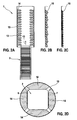
- FIG. 2A shows an embodiment of the invention with a piezoelectric actuator 2 prior to assembly in the sleeve 10 in the insertion direction 13, in which a molded element 14 with fins 15 on the inside of the sleeve 10, for example, glued or vulcanized.
- Figure 2B and Figure 2C each show alternative embodiments or sizes of the fins or scales 15 of the formula element 14th
- FIG. 2D shows a cross section of the arrangement described above, from which it can be seen that a plurality of mold elements 14 are bead-like in each case opposite the side surfaces of the piezoelectric actuator 2.
- FIG. 3A is an example with a piezo actuator with a piezo actuator 2 in off
- FIG. 3A is an example with a piezoelectric actuator 2 in the sleeve 10 can be seen in which a molded element 16 with a convex curvature before assembly of the piezoelectric actuator 2 is pushed or mounted on this and then the piezoelectric actuator 2 was pressed with the mold member 16 in the sleeve 10.
- FIG. 3B shows an approximately central cross-section of the arrangement described above.
- FIG. 4A an example is shown with a piezoelectric actuator 2 prior to assembly in the sleeve 10 in the insertion direction 13, in which a convexly curved mold element 17 is glued or vulcanized on the inside of the sleeve 10, for example.
- FIG. 4B shows an approximately central cross-section of the arrangement described above, from which it can be seen that a plurality of mold elements 17 are bead-like in each case opposite the side surfaces of the piezoelectric actuator 2 and are interconnected only by webs 17a.
- FIG. 5A shows a further example with a piezoelectric actuator 2 prior to assembly in the sleeve 10 in the insertion direction 13, in which a molding element 18 is glued or vulcanized with, for example, in the longitudinal direction sections beads 19 in the sleeve 10.
- FIG. 5B this arrangement is recognizable after assembly of the piezoelectric actuator 2 in the sleeve 10 and
- FIG. 5C shows an approximately central cross section of the arrangement described above, from which it can be seen that the mold element 18 abuts in the illustration right above with beads 19 each on the side surfaces of the piezoelectric actuator 2 or alternatively with multiple beads 19 on the side surfaces (left illustration) or . Also at the corners (lower Dart ein) of the piezoelectric actuator 2 is applied.
- FIG. 6 is yet to take an example with a piezoelectric actuator 2 prior to assembly in the sleeve 10 in the insertion direction 13, in which, in a modification to the embodiment of the FIGS. 5a to 5c a mold element 20 is designed so that this is pushed or mounted on the piezoelectric actuator 2 prior to assembly and in the longitudinal extension sections beads 21 taper in the insertion direction 13 in cross-section conical to facilitate insertion into the sleeve 10.
Landscapes
- Engineering & Computer Science (AREA)
- Manufacturing & Machinery (AREA)
- Fuel-Injection Apparatus (AREA)
- General Electrical Machinery Utilizing Piezoelectricity, Electrostriction Or Magnetostriction (AREA)
Description
Die Erfindung betrifft eine Anordnung eines Piezoaktors in einer Hülse eines Piezoaktormoduls, ein Herstellungsverfahren sowie eine Verwendung des Piezoaktormoduls nach den gattungsgemäßen Merkmalen der Hauptansprüche.The invention relates to an arrangement of a piezoelectric actuator in a sleeve of a piezoelectric actuator, a manufacturing method and a use of the piezoelectric actuator according to the generic features of the main claims.
Ein solches Piezoaktormodul kann beispielsweise in einem Piezoinjektor zur mengen- und zeitgenauen Dosierung von Kraftstoff für einen Verbrennungsmotor eingesetzt werden. Der Piezoinjektor besteht im Wesentlichen aus einem Haltekörper und dem in dem Haltekörper angeordneten Piezoaktor, der mehrere übereinander gestapelte, zwischen einem Kopf- und Fußteil angeordnete Piezoelemente aufweist.Such a piezoelectric actuator module can be used, for example, in a piezo injector for the metered and precise metering of fuel for an internal combustion engine. The piezoelectric injector consists essentially of a holding body and arranged in the holding body piezoelectric actuator having a plurality of stacked, arranged between a head and foot part piezo elements.
Es ist an sich bekannt, dass zum Aufbau des zuvor erwähnten Piezoaktors die Piezoelemente so eingesetzt werden können, dass unter Ausnutzung des sogenannten Piezoeffekts eine Steuerung des Nadelhubes eines Ventils oder dergleichen vorgenommen werden kann. Piezolagen der Piezoelemente sind aus einem Material mit einer geeigneten Kristallstruktur so aufgebaut, dass bei Anlage einer äußeren elektrischen Spannung eine mechanische Reaktion der Piezoelemente erfolgt, die in Abhängigkeit von der Kristallstruktur und der Anlagebereiche der elektrischen Spannung einen Druck oder Zug in eine vorgebbare Richtung darstellt. Derartige Piezoaktoren eignen sich beispielsweise für Anwendungen, bei denen Hubbewegungen unter hohen Betätigungskräften und hohen Taktfrequenzen ablaufen.It is known per se that for the construction of the aforementioned piezoelectric actuator, the piezoelectric elements can be used so that by utilizing the so-called piezoelectric effect, a control of the needle stroke of a valve or the like can be made. Piezo layers of the piezoelectric elements are constructed of a material having a suitable crystal structure such that upon application of an external electrical voltage, a mechanical reaction of the piezoelectric elements occurs, which represents a pressure or tension in a predeterminable direction as a function of the crystal structure and the contact regions of the electrical voltage. Such piezoelectric actuators are suitable, for example, for applications in which lifting movements take place under high operating forces and high clock frequencies.
Beispielsweise ist ein solcher Piezoaktor als Bestandteil eines Piezoinjektors in sogenannten Common Rail Einspritzsystemen (CR-Injektor) aus der
Um eine elektrische und mechanische Isolierung des Piezoaktors zu erreichen, wird oft auch eine flexible Ummantelung des Piezoaktors vorgeschlagen. Aus der
Bei dieser bekannten Anordnung müssen in der Regel für das Befüllen des Piezoaktormoduls mit der Vergussmasse Moduls und zum Vernetzen dieser Vergussmasse im Piezoaktormodul in der Fertigungslinie zwei Fertigungsstationen vorgesehen werden, die insbesondere auch kostenaufwändig sind.In this known arrangement, two production stations usually have to be provided for filling the piezoelectric actuator module with the potting compound and for crosslinking this potting compound in the piezoelectric actuator module in the production line, which in particular are also costly.
Aus dem Stand der Technik sind weiterhin die
Die Erfindung geht von einem eingangs beschriebenen Piezoaktormodul mit einem Piezoaktor und einer den Piezoaktor umgebenden Hülse aus, wobei zwischen der Hülse und dem Piezoaktor mindestens teilweise eine Isolationsmasse angeordnet ist. Erfindungsgemäß ist die Isolationsmasse in vorteilhafter Weise aus mindestens einem separat hergestellten, vorgeformten plastischen und/oder elastischen Formelement gebildet, dass zwischen den Piezoaktor und die Hülse einbringbar ist und sich in einem vorgegebenen Bereich über die Länge des Piezoaktors erstreckt. Hierbei ist das mindestens eine Formelement aus einem wärmeleitenden Material hergestellt.The invention is based on a piezoelectric actuator described above with a piezoelectric actuator and a sleeve surrounding the piezoelectric actuator, wherein at least partially an insulating compound is arranged between the sleeve and the piezoelectric actuator. According to the invention, the insulation compound is in formed advantageously from at least one separately prepared, preformed plastic and / or elastic mold element that can be introduced between the piezoelectric actuator and the sleeve and extending in a predetermined range over the length of the piezoelectric actuator. Here, the at least one molding element is made of a thermally conductive material.
Gemäß einer Ausführungsform erstreckt sich das mindestens eine Formelement in einem vorgegebenen Bereich über die Länge des Piezoaktors linear.According to one embodiment, the at least one shaped element extends linearly in a predetermined region over the length of the piezoelectric actuator.
Erfindungsgemäβ erstreckt sich das mindestens eine Formelement in einem vorgegebenen Bereich über die Länge des Piezoaktors wulstartig dem Piezoaktor zugewandt so wie durch Anspruch 1 definiert, damit beim Einführen des Piezoaktors in die Hülse ein sanfter Übergang durch eine kontinuierliche Erhöhung des Anpressdrucks erreicht wird. Ein zum Piezoaktor hin konvex geformtes Formelement ist vorteilhaft bei einem vor der Montage des Piezoaktors an die Hülse angefügten Formelement und ein zur Hülse hin konvex geformtes Formelement ist vorteilhaft bei einem vor der Montage des Piezoaktors an den Piezoaktor angefügten Formelement anwendbar.According to the invention, the at least one shaped element extends in a predetermined region over the length of the piezoelectric actuator bead-like the piezoelectric actuator as defined by
Bei dem erfindungsgemäßen Piezoaktormodul sind an dem mindestens einen Formelement lamellen- oder schuppenförmige Erweiterungen vorhanden, die zum Kontakt mit dem Piezoaktor gerichtet sind. Auch hierbei ist sichergestellt, dass sich die lamellen- oder schuppenförmigen Erweiterungen beim Einschieben des Piezoaktors sanft an die gegenüberliegende Wand anlegen und somit eine leichte Montage bei gutem wärmeableitendem Kontakt ermöglichen. Zum Piezoaktor hinzeigende lamellen- oder schuppenförmige Erweiterungen werden vorteilhaft bei einem vor der Montage des Piezoaktors an die Hülse angefügten Formelement vorgesehen.In the case of the piezoelectric actuator module according to the invention, lamellar or scale-shaped extensions are provided on the at least one molding element and are intended for contact with the piezoelectric actuator. Here, too, it is ensured that the lamellar or scale-shaped extensions when inserting the piezoelectric actuator gently create the opposite wall and thus allow easy installation with good heat-dissipating contact. For the piezoelectric actuator hinzeigende lamellar or scale-like extensions are advantageously provided at an attached prior to assembly of the piezoelectric actuator to the sleeve mold element.
Bei einem erfindungsgemäβen Verfahren zur Herstellung eines erfindungsgemäßen Piezoaktormoduls wie durch Anspruch 4 definiert wird das mindestens eine Formelement an die Innenseite der Hülse vor dem Einbringen des Piezoaktors geklebt, extrudiert oder vulkanisiert. Es kann aber auch alternativ auf einfache Weise das mindestens eine entsprechend ausgebildete Formelement vor dem Einbringen des Piezoaktors in die Hülse auf den Piezoaktor gezogen, geschoben, gepresst oder sonst wie aufgebracht und anschließend die Hülse vorzugsweise aufgepresst werden.In a erfindungsgemäβen method for producing a piezoelectric actuator according to the invention as defined by
Als Material für die Formelemente kommen beispielsweise Kunststoffe wie TPE oder LSR in Frage, die gefüllt oder ungefüllt sein können.As a material for the mold elements, for example, plastics such as TPE or LSR come into question, which may be filled or unfilled.
Eine vorteilhafte Verwendung des erfindungsgemäßen Piezoaktormoduls ergibt sich, wenn das Piezoaktormodul Bestandteil eines Piezoinjektors für ein Einspritzsystem für Kraftstoff bei einem Verbrennungsmotor ist, wobei der Kraftstoff die Hülse des Piezoaktormoduls umströmt.An advantageous use of the piezoelectric actuator according to the invention results when the piezoelectric actuator is part of a piezoelectric injector for an injection system for fuel in an internal combustion engine, wherein the fuel flows around the sleeve of the piezoelectric actuator module.
Ausführungsbeispiele der erfindungsgemäßen Anordnung eines Piezoaktors in einem Piezoaktormodul werden anhand der Zeichnung erläutert. Es zeigen:
- Figur 1A
- einen Längsschnitt durch ein nicht erfindungsgemäßes Piezoaktormodul mit einem Piezoaktor und einem Formelement mit lamellenförmigen Erweiterungen in einer Hülse,
- Figur 1B
- einen Querschnitt durch das Piezoaktormodul nach der
Figur 1A , - Figur 2A
- einen Längsschnitt durch ein erfindungsgemäßes Piezoaktormodul vor der Montage mit einem Piezoaktor und einem Formelement mit Lamellen in der Hülse,
- Figuren 2B und 2C
- Ausführungsbeispiel von lamellen- oder schuppenförmigen Erweiterungen des Formelements,
- Figur 2D
- einen Querschnitt durch das Piezoaktormodul nach der
Figur 2A nach der Montage, - Figuren 3A und 3B
- einen Längsschnitt und einen Querschnitt durch ein nicht erfindungsgemäßes Piezoaktormodul mit einem Piezoaktor und einem Formelement mit konvexen Wölbungen am Piezoaktor,
- Figur 4A
- einen Längsschnitt durch ein nicht erfindungsgemäßes Piezoaktormodul vor der Montage mit einem Piezoaktor und einem Formelement mit konvexen Wölbungen in der Hülse,
- Figur 4B
- einen Querschnitt durch das Piezoaktormodul nach der
Figur 4A nach der Montage, - Figur 5A
- einen Längsschnitt durch ein nicht erfindungsgemäßes Piezoaktormodul vor der Montage mit einem Piezoaktor und einem Formelement mit in der Längserstreckung abschnittsweisen Wülsten in der Hülse,
- Figuren 5B und 5C
- einen Längsschnitt und einen Querschnitt durch das Piezoaktormodul nach der
Figur 5A nach der Montage mit alternativen Anordnungen der Wülste und Figur 6- einen Längsschnitt durch ein nicht erfindungsgemäßes Piezoaktormodul vor der Montage mit einem Piezoaktor und einem Formelement mit in der Längserstreckung abschnittsweise angeordneten, im Querschnitt konisch in Einschubrichtung verkleinerten Wülsten in der Hülse.
- Figure 1A
- a longitudinal section through a non-inventive piezoelectric actuator with a piezoelectric actuator and a molding element with lamellar extensions in a sleeve,
- FIG. 1B
- a cross section through the piezoelectric actuator according to the
Figure 1A . - FIG. 2A
- a longitudinal section through a piezoelectric actuator according to the invention prior to assembly with a piezoelectric actuator and a form element with fins in the sleeve,
- FIGS. 2B and 2C
- Embodiment of lamellar or scale-like extensions of the formula element,
- FIG. 2D
- a cross section through the piezoelectric actuator according to the
FIG. 2A after assembly, - FIGS. 3A and 3B
- a longitudinal section and a cross section through a non-inventive piezoelectric actuator with a piezoelectric actuator and a mold element with convex curvatures on the piezoelectric actuator,
- FIG. 4A
- a longitudinal section through a non-inventive piezoelectric actuator before assembly with a piezoelectric actuator and a shaped element with convex curvatures in the sleeve,
- FIG. 4B
- a cross section through the piezoelectric actuator according to the
FIG. 4A after assembly, - FIG. 5A
- a longitudinal section through a non-inventive piezoelectric actuator before assembly with a piezoelectric actuator and a mold element with in the longitudinal direction sections beads in the sleeve,
- Figures 5B and 5C
- a longitudinal section and a cross section through the piezoelectric actuator according to the
FIG. 5A after assembly with alternative arrangements of the beads and - FIG. 6
- a longitudinal section through a non-inventive piezoelectric actuator prior to assembly with a piezoelectric actuator and a mold element with arranged in the longitudinal direction in sections, in cross-section conically reduced in the insertion direction beads in the sleeve.
In
Um den Piezoaktor 2 bzw. das Piezoaktormodul 1 vor umströmenden Medien, wie zum Beispiel Kraftstoff, und vor sonstigen schädlichen Einwirkungen zu schützen, ist eine verschließbare Hülse 10 vorhanden und der Piezoaktor 2 ist von einem plastischen und/oder elastischen Formelement 11 umhüllt, das zur elektrischen Isolation des Piezoaktors 2 und zur Wärmeabfuhr vom Piezoaktor 2 an die Hülse 10 dient.In order to protect the
Erfindungsgemäß weist das Formelement 11 lamellen- oder schuppenförmige Erweiterungen 12 auf, die eine gelichmäßige Wärmeabfuhr an allen Stellen des Piezoaktors 2 und eine einfache Montage durch ein sanftes Anliegen der lamellen- oder schuppenförmigen Erweiterungen 12 an die Hülse 10 während der Montage ermöglichen. Hier wurde das Formelement 11 vor der Montage des Piezoaktors 2 auf diesen aufgeschoben oder aufgezogen und dann der Piezoaktor 2 mit dem Formelement 11 in die Hülse eingepresst.According to the invention, the
Die Anordnung der lamellen- oder schuppenförmigen Erweiterungen 12 kann wahlweise auf einer oder mehreren Seiten des Piezoaktors 2 vorgenommen werden, wie es aus einem Querschnitt nach
Aus
In
Aus
Claims (5)
- Piezo-actuator module (1) having a piezo-actuator (2) and a sleeve (10) which surrounds the piezo-actuator (2), an isolating material being arranged at least partially between the sleeve (10) and the piezo-actuator (2), which isolating material is formed from at least one separately produced, preformed plastic and/or elastic shaped element (11; 14; 16; 17; 18; 20) which is produced from a thermally conducting material, can be introduced between the piezo-actuator (2) and the sleeve (10) and extends in a predefined region over the length of the piezo-actuator (2), characterized in that there are a plurality of separate shaped elements (14; 17; 18; 20) distributed on the circumference of the piezo-actuator (2), which shaped elements (14; 17; 18; 20) are adhesively bonded or vulcanized on the inner side of the sleeve (10) and in each case lie opposite the side faces of the piezo-actuator (2) in a bead-like manner, there being lamellar or imbricated widened portions (12; 15) on the shaped elements (11; 14), which widened portions (12; 15) are directed for contact with the piezo-actuator (2).
- Piezo-actuator module according to Claim 1, characterized in that the at least one shaped element (11; 14; 16; 17; 18; 20) extends linearly in a predefined region over the length of the piezo-actuator (2).
- Piezo-actuator module according to Claim 1, characterized in that, in the case of a piezo-actuator (2) with a rectangular cross section, there are two or four shaped elements (14; 17; 18), of which in each case one is arranged between the sleeve (10) and at least opposite side faces of the piezo-actuator (2).
- Method for producing a piezo-actuator module according to one of the preceding claims, characterized in that the at least one shaped element (14; 17; 18) is adhesively bonded or vulcanized to the inner side of the sleeve before the introduction of the piezo-actuator, and the piezo-actuator (2) is then introduced, is preferably pressed in.
- Use of a piezo-actuator module (1) as a constituent part of a piezo-injector for an injection system in an internal combustion engine, the fuel flowing around the sleeve (10) of the piezo-actuator module (1), characterized in that the piezo-actuator module (1) is configured according to one of Claims 1 to 3.
Applications Claiming Priority (1)
| Application Number | Priority Date | Filing Date | Title |
|---|---|---|---|
| DE102006051325A DE102006051325A1 (en) | 2006-10-31 | 2006-10-31 | Arrangement of a piezoelectric actuator in a sleeve of a piezoelectric actuator module |
Publications (3)
| Publication Number | Publication Date |
|---|---|
| EP1919005A2 EP1919005A2 (en) | 2008-05-07 |
| EP1919005A3 EP1919005A3 (en) | 2011-11-02 |
| EP1919005B1 true EP1919005B1 (en) | 2013-04-10 |
Family
ID=38983751
Family Applications (1)
| Application Number | Title | Priority Date | Filing Date |
|---|---|---|---|
| EP07116902.3A Not-in-force EP1919005B1 (en) | 2006-10-31 | 2007-09-21 | Assembly of a piezo actuator in the casing of a piezo actuator module |
Country Status (2)
| Country | Link |
|---|---|
| EP (1) | EP1919005B1 (en) |
| DE (1) | DE102006051325A1 (en) |
Families Citing this family (2)
| Publication number | Priority date | Publication date | Assignee | Title |
|---|---|---|---|---|
| EP2405503B1 (en) * | 2009-03-04 | 2015-11-25 | Kyocera Corporation | Laminated piezoelectric element, jetting device provided with same, and fuel jetting system |
| RU2447544C1 (en) * | 2010-12-01 | 2012-04-10 | Федеральное государственное бюджетное образовательное учреждение высшего профессионального образования "Национальный исследовательский университет "МИЭТ" | Piezoelectric device |
Family Cites Families (9)
| Publication number | Priority date | Publication date | Assignee | Title |
|---|---|---|---|---|
| US4958101A (en) * | 1988-08-29 | 1990-09-18 | Toyota Jidosha Kabushiki Kaisha | Piezoelectric actuator |
| DE19856185A1 (en) * | 1998-12-05 | 2000-06-15 | Bosch Gmbh Robert | Piezoelectric drive |
| DE19857247C1 (en) * | 1998-12-11 | 2000-01-27 | Bosch Gmbh Robert | Piezoelectric actuator for actuating control or injection valves in motor vehicle internal combustion engines |
| DE19857547C1 (en) | 1998-12-14 | 2000-08-03 | Cognis Deutschland Gmbh | New N,O-substituted chitins and chitosans prepared by alkoxylation, N-substitution with aldoses or ketones followed by reduction, useful as additives for cosmetics, e.g. shampoos and suntan lotions |
| DE19914411A1 (en) * | 1999-03-30 | 2000-10-12 | Bosch Gmbh Robert | Piezoelectric actuator |
| DE10026005B4 (en) | 2000-05-25 | 2004-07-08 | Robert Bosch Gmbh | piezo actuator |
| DE10054017A1 (en) * | 2000-11-01 | 2002-05-08 | Bosch Gmbh Robert | Piezo-actuator module, especially for fuel injection system, has sheath element designed as heat-conducting rubber element which has shell-shaped design and lies directly on piezo-actuator |
| DE10230032A1 (en) | 2002-07-04 | 2004-01-22 | Daimlerchrysler Ag | Piezoelectric actuator for flowing media and use of a corresponding piezoelectric actuator |
| JP2006303443A (en) * | 2005-03-24 | 2006-11-02 | Ngk Spark Plug Co Ltd | Piezoelectric element, manufacturing method of multilayer piezoelectric element and fuel injector using the same |
-
2006
- 2006-10-31 DE DE102006051325A patent/DE102006051325A1/en not_active Withdrawn
-
2007
- 2007-09-21 EP EP07116902.3A patent/EP1919005B1/en not_active Not-in-force
Also Published As
| Publication number | Publication date |
|---|---|
| DE102006051325A1 (en) | 2008-05-08 |
| EP1919005A2 (en) | 2008-05-07 |
| EP1919005A3 (en) | 2011-11-02 |
Similar Documents
| Publication | Publication Date | Title |
|---|---|---|
| EP1906464B1 (en) | Piezo actuator with a jacket for placing in a piezo injector | |
| EP1901360B1 (en) | Piezo actuator module with a cladded piezo actuator | |
| DE102006026152A1 (en) | Arrangement with a coated piezoelectric actuator | |
| EP1714024B1 (en) | Fuel system part with a cable leadthrough | |
| EP1919005B1 (en) | Assembly of a piezo actuator in the casing of a piezo actuator module | |
| WO2007131965A1 (en) | Piezoactuator | |
| EP2058873B1 (en) | Piezo actuator and piezo actuator module with a protective coating system | |
| EP2031669B1 (en) | Piezo actuator module having a piezo actuator sleeve and method for its manufacture | |
| EP2396535B1 (en) | Piezoelectric actuator, method for producing the actuator, and injector | |
| DE102007042216A1 (en) | Piezo actuator module production method for internal combustion engine, involves clamping actuators between head and base, where actuators are provided with casing fastened by pressing of metal part by electromagnetic forming process | |
| WO2007118726A1 (en) | Actuator module | |
| DE102005045229A1 (en) | Arrangement with a piezoelectric actuator and a method for its production | |
| DE102006043709A1 (en) | Piezo actuator arrangement for controlling of needle stroke in injection system, has isolation mass partially arranged between covering and piezo unit that is clamped between actuator foot and actuator head | |
| EP2013922A1 (en) | Piezoelectric actuator module having a sheath, and a method for producing said module | |
| EP1820960B1 (en) | Fuel injector | |
| EP1909339B1 (en) | Actuator module having an enshrouded piezo actuator | |
| EP2034532A1 (en) | Piezoelectric actuator module with a protective layer system and method for its manufacture | |
| DE102009027101A1 (en) | Flexible casing for piezoelectric actuator for fuel injection system of air compression, self ignition internal combustion engine, has internal recesses, where is positioned partially against outer surface of actuator in expanded condition | |
| EP2079117A2 (en) | Piezo actuator module with multiple piezo actuators and method for its manufacture | |
| EP1909338B1 (en) | Piezo actuator assembly with an insulating layer | |
| DE102014215327A1 (en) | Piezo actuator for a fuel injector and fuel injector | |
| EP1919004B1 (en) | Piezo actuator module or piezo actuator with a cladded protection layer system | |
| EP2649295B1 (en) | Piezoelectric actuator module and fuel injection valve | |
| DE102007042400A1 (en) | Piezoactuator module with a protective layer system and a method for its production | |
| DE102007056553A1 (en) | Method for producing piezo actuator module, involves applying isolation protective layer made of plastic as passivating casing, which is created in electrically conductive manner by coating process |
Legal Events
| Date | Code | Title | Description |
|---|---|---|---|
| PUAI | Public reference made under article 153(3) epc to a published international application that has entered the european phase |
Free format text: ORIGINAL CODE: 0009012 |
|
| AK | Designated contracting states |
Kind code of ref document: A2 Designated state(s): AT BE BG CH CY CZ DE DK EE ES FI FR GB GR HU IE IS IT LI LT LU LV MC MT NL PL PT RO SE SI SK TR |
|
| AX | Request for extension of the european patent |
Extension state: AL BA HR MK RS |
|
| PUAL | Search report despatched |
Free format text: ORIGINAL CODE: 0009013 |
|
| AK | Designated contracting states |
Kind code of ref document: A3 Designated state(s): AT BE BG CH CY CZ DE DK EE ES FI FR GB GR HU IE IS IT LI LT LU LV MC MT NL PL PT RO SE SI SK TR |
|
| AX | Request for extension of the european patent |
Extension state: AL BA HR MK RS |
|
| RIC1 | Information provided on ipc code assigned before grant |
Ipc: H01L 41/053 20060101AFI20110928BHEP Ipc: F02M 51/06 20060101ALI20110928BHEP |
|
| 17P | Request for examination filed |
Effective date: 20120502 |
|
| AKX | Designation fees paid |
Designated state(s): CZ DE FR IT |
|
| 17Q | First examination report despatched |
Effective date: 20120711 |
|
| REG | Reference to a national code |
Ref country code: DE Ref legal event code: R079 Ref document number: 502007011589 Country of ref document: DE Free format text: PREVIOUS MAIN CLASS: H01L0041053000 Ipc: H02N0002020000 |
|
| RIC1 | Information provided on ipc code assigned before grant |
Ipc: F02M 51/06 20060101ALI20121030BHEP Ipc: H01L 41/22 20060101ALI20121030BHEP Ipc: H01L 41/053 20060101ALI20121030BHEP Ipc: H02N 2/04 20060101ALI20121030BHEP Ipc: H02N 2/02 20060101AFI20121030BHEP |
|
| GRAP | Despatch of communication of intention to grant a patent |
Free format text: ORIGINAL CODE: EPIDOSNIGR1 |
|
| GRAS | Grant fee paid |
Free format text: ORIGINAL CODE: EPIDOSNIGR3 |
|
| GRAA | (expected) grant |
Free format text: ORIGINAL CODE: 0009210 |
|
| AK | Designated contracting states |
Kind code of ref document: B1 Designated state(s): CZ DE FR IT |
|
| REG | Reference to a national code |
Ref country code: DE Ref legal event code: R096 Ref document number: 502007011589 Country of ref document: DE Effective date: 20130606 |
|
| PG25 | Lapsed in a contracting state [announced via postgrant information from national office to epo] |
Ref country code: CZ Free format text: LAPSE BECAUSE OF FAILURE TO SUBMIT A TRANSLATION OF THE DESCRIPTION OR TO PAY THE FEE WITHIN THE PRESCRIBED TIME-LIMIT Effective date: 20130410 |
|
| PLBE | No opposition filed within time limit |
Free format text: ORIGINAL CODE: 0009261 |
|
| STAA | Information on the status of an ep patent application or granted ep patent |
Free format text: STATUS: NO OPPOSITION FILED WITHIN TIME LIMIT |
|
| PG25 | Lapsed in a contracting state [announced via postgrant information from national office to epo] |
Ref country code: IT Free format text: LAPSE BECAUSE OF FAILURE TO SUBMIT A TRANSLATION OF THE DESCRIPTION OR TO PAY THE FEE WITHIN THE PRESCRIBED TIME-LIMIT Effective date: 20130410 |
|
| 26N | No opposition filed |
Effective date: 20140113 |
|
| REG | Reference to a national code |
Ref country code: DE Ref legal event code: R097 Ref document number: 502007011589 Country of ref document: DE Effective date: 20140113 |
|
| REG | Reference to a national code |
Ref country code: FR Ref legal event code: ST Effective date: 20140530 |
|
| PG25 | Lapsed in a contracting state [announced via postgrant information from national office to epo] |
Ref country code: FR Free format text: LAPSE BECAUSE OF NON-PAYMENT OF DUE FEES Effective date: 20130930 |
|
| PGFP | Annual fee paid to national office [announced via postgrant information from national office to epo] |
Ref country code: DE Payment date: 20191125 Year of fee payment: 13 |
|
| REG | Reference to a national code |
Ref country code: DE Ref legal event code: R119 Ref document number: 502007011589 Country of ref document: DE |
|
| PG25 | Lapsed in a contracting state [announced via postgrant information from national office to epo] |
Ref country code: DE Free format text: LAPSE BECAUSE OF NON-PAYMENT OF DUE FEES Effective date: 20210401 |