EP1918955A1 - Keypad having keys with angled engagement surfaces, and associated handheld electronic device - Google Patents
Keypad having keys with angled engagement surfaces, and associated handheld electronic device Download PDFInfo
- Publication number
- EP1918955A1 EP1918955A1 EP06123206A EP06123206A EP1918955A1 EP 1918955 A1 EP1918955 A1 EP 1918955A1 EP 06123206 A EP06123206 A EP 06123206A EP 06123206 A EP06123206 A EP 06123206A EP 1918955 A1 EP1918955 A1 EP 1918955A1
- Authority
- EP
- European Patent Office
- Prior art keywords
- keypad
- keys
- key
- reference axis
- column
- Prior art date
- Legal status (The legal status is an assumption and is not a legal conclusion. Google has not performed a legal analysis and makes no representation as to the accuracy of the status listed.)
- Granted
Links
- 238000010348 incorporation Methods 0.000 abstract 1
- 238000004891 communication Methods 0.000 description 2
- 230000006870 function Effects 0.000 description 2
- 230000001413 cellular effect Effects 0.000 description 1
- 238000005516 engineering process Methods 0.000 description 1
- 238000012986 modification Methods 0.000 description 1
- 230000004048 modification Effects 0.000 description 1
- 230000000007 visual effect Effects 0.000 description 1
Images


Classifications
-
- H—ELECTRICITY
- H01—ELECTRIC ELEMENTS
- H01H—ELECTRIC SWITCHES; RELAYS; SELECTORS; EMERGENCY PROTECTIVE DEVICES
- H01H13/00—Switches having rectilinearly-movable operating part or parts adapted for pushing or pulling in one direction only, e.g. push-button switch
- H01H13/70—Switches having rectilinearly-movable operating part or parts adapted for pushing or pulling in one direction only, e.g. push-button switch having a plurality of operating members associated with different sets of contacts, e.g. keyboard
- H01H13/84—Switches having rectilinearly-movable operating part or parts adapted for pushing or pulling in one direction only, e.g. push-button switch having a plurality of operating members associated with different sets of contacts, e.g. keyboard characterised by ergonomic functions, e.g. for miniature keyboards; characterised by operational sensory functions, e.g. sound feedback
-
- G—PHYSICS
- G06—COMPUTING; CALCULATING OR COUNTING
- G06F—ELECTRIC DIGITAL DATA PROCESSING
- G06F1/00—Details not covered by groups G06F3/00 - G06F13/00 and G06F21/00
- G06F1/16—Constructional details or arrangements
- G06F1/1613—Constructional details or arrangements for portable computers
- G06F1/1633—Constructional details or arrangements of portable computers not specific to the type of enclosures covered by groups G06F1/1615 - G06F1/1626
- G06F1/1662—Details related to the integrated keyboard
-
- H—ELECTRICITY
- H04—ELECTRIC COMMUNICATION TECHNIQUE
- H04M—TELEPHONIC COMMUNICATION
- H04M1/00—Substation equipment, e.g. for use by subscribers
- H04M1/02—Constructional features of telephone sets
- H04M1/23—Construction or mounting of dials or of equivalent devices; Means for facilitating the use thereof
-
- H—ELECTRICITY
- H01—ELECTRIC ELEMENTS
- H01H—ELECTRIC SWITCHES; RELAYS; SELECTORS; EMERGENCY PROTECTIVE DEVICES
- H01H2217/00—Facilitation of operation; Human engineering
- H01H2217/004—Larger or different actuating area
-
- H—ELECTRICITY
- H01—ELECTRIC ELEMENTS
- H01H—ELECTRIC SWITCHES; RELAYS; SELECTORS; EMERGENCY PROTECTIVE DEVICES
- H01H2217/00—Facilitation of operation; Human engineering
- H01H2217/024—Profile on actuator
-
- H—ELECTRICITY
- H01—ELECTRIC ELEMENTS
- H01H—ELECTRIC SWITCHES; RELAYS; SELECTORS; EMERGENCY PROTECTIVE DEVICES
- H01H2217/00—Facilitation of operation; Human engineering
- H01H2217/028—Facilitation of operation; Human engineering on planes with different or alterable inclination, e.g. convex plane
Definitions
- the disclosed and claimed concept relates generally to handheld electronic devices and, more particularly, to a keypad of a handheld electronic device.
- handheld electronic devices Numerous types of handheld electronic devices are known. Examples of such handheld electronic devices include, for instance, personal data assistants (PDAs), handheld computers, two-way pagers, cellular telephones, and the like. Many handheld electronic devices also feature a wireless communication capability, although many such handheld electronic devices are stand-alone devices that are functional without communication with other devices.
- PDAs personal data assistants
- handheld computers two-way pagers
- cellular telephones and the like.
- Many handheld electronic devices also feature a wireless communication capability, although many such handheld electronic devices are stand-alone devices that are functional without communication with other devices.
- handheld electronic devices include a keypad that comprises a plurality of keys that are actuatable in one fashion or another.
- a handheld electronic device having a small form factor typically must also have a small keypad which typically will have either relatively small keys and/or relatively few keys. Keys that are relatively small can be difficult for a user to locate and actuate during use of the handheld electronic device. It thus would be desirable to provide an improved keypad and handheld electronic device wherein the keys are configured to be relatively easy for a user to locate and to actuate.
- Fig. 1 is a front elevational view of an improved keypad in accordance with a first embodiment of the disclosed and claimed concept
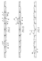
- Fig. 2 is a sectional view as taken along Line 2-2 of Fig. 1;
- Fig. 2A is a view similar to Fig. 2, except depicting a portion of the keypad and a particular key thereof in an actuated condition;
- Fig. 3 is a sectional view as taken along Line 3-3 of Fig. 1;
- Fig. 3A is a view similar to Fig. 3, except depicting a portion of the keypad and depicting in an actuated condition the same key as is depicted in Fig. 2A as being in the actuated condition;
- Fig. 4 is a sectional view as taken along Line 4-4 of Fig. 1;
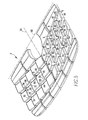
- Fig. 5 is a perspective of the keypad of Fig. 1;
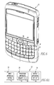
- Fig. 6 is an improved handheld electronic device which, for example, incorporates the improved keypad of Fig. 1;
- Fig. 6A is a schematic depiction of the handheld electronic device of Fig. 6;
- Fig. 7 is an enlarged view of a portion of the keypad of Fig. 5;
- Fig. 8 is a front elevational view of an improved keypad in accordance with a second embodiment of the disclosed and claimed concept
- Fig. 9 is a sectional view as taken along Line 9-9 of Fig. 8;
- Fig. 10 is a sectional view as taken along Line 10-10 of Fig. 8;
- Fig. 11 is a sectional view as taken along Line 11-11 of Fig. 8;
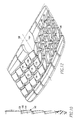
- Fig. 12 is a perspective view of the keypad of Fig. 8;
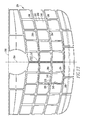
- Fig. 13 is a front elevational view of an improved keypad in accordance with a third embodiment of the disclosed and claimed concept.
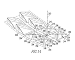
- Fig. 14 is a perspective view of a portion of the keypad of Fig. 13.
- FIG. 1-5 An improved keypad 4 in accordance with the disclosed and claimed concept is depicted generally in Figs. 1-5.
- the keypad 4 includes a plurality of keys 8 that are actuatable between an unactuated condition, as is depicted in Figs. 1, 2, 3, 4, and 5, and an actuated condition, as is depicted in an exemplary fashion in Figs. 2A and 3A.
- the improved keypad 4 is advantageously arranged in a stepped layout that will be described in greater detail elsewhere herein.
- the improved keypad 4 can be incorporated into a handheld electronic device 12, such as is depicted in an exemplary fashion in Fig. 6 and is depicted in a schematic fashion in Fig. 6A.
- the improved handheld electronic device 12 comprises an input apparatus 16, a processor apparatus 20, and an output apparatus 24.
- the input apparatus 16 includes the keypad 4 and can include other input members such as a trackball 26 and other such input members.
- the processor apparatus 20 comprises a processor 28, such as a microprocessor ( ⁇ P) or other processor, and further comprises a memory 32 which can be any of a variety of known storage devices.
- the output apparatus 24 comprises a display 36.
- the memory 32 has stored therein a number of routines that are executable on the processor 28.
- the processor apparatus 20 receives input signals from the input apparatus 16 and provides output signals to the output apparatus 24.
- a key 8 in its actuated condition closes a circuit of the handheld electronic device 12 to provide an input to the processor apparatus 20.
- the keys 8 each include an outer surface 40 and a skirt surface 44 which, in the depicted exemplary embodiment, are disposed adjacent one another.
- the outer surface 40 comprises an engagement surface 48 that is engageable by the user in actuating the key 8 between the unactuated and actuated conditions.
- a force applied to the engagement surface 48 of a key 8 overcomes a bias of the key 8 in an outward direction along an actuation axis 60 and translates the key 8 from the unactuated condition to the actuated condition.
- a release of the force allows the bias to return the key 8 from the actuated condition to the unactuated condition.
- the keys 8 in other embodiments could be configured in known fashions to be actuatable in a direction along their actuation axis 60 with minimal translation or with no translation without departing from the present concept.
- the keys 8 are arranged in a plurality of columns 52 and in a plurality of rows 56.
- the columns 52 are straight and are parallel with one another.
- the rows 56 are parallel with one another and are generally curved. Since the curvature of each of the rows 56 is axisymmetric with respect to a first reference axis 64 of the keypad 4, each row 56 can be said to extend substantially parallel with a second reference axis 68 of the keypad 4.
- Each key 8 is generally actuatable along its actuation axis 60 between the unactuated and actuated conditions.
- the actuation axis 60 is substantially orthogonal to the first reference axis 64 and the second reference axis 68. That is, the actuation axis 60, the first reference axis 64, and the second reference axis 68 are mutually substantially perpendicular to one another.
- the actuation axis 60 of a give key 8 may be parallel with the actuation axis 60 of one or more other keys 8, or may be nonparallel with the actuation axis 60 of each other key.
- the engagement surface 48 of each of the keys 8 is oriented oblique to the actuation axis 60 thereof.
- the expression "oblique" and variations thereof shall refer broadly to a relationship that is neither parallel nor perpendicular.
- the engagement surface 48 can be said to be oriented at a first angle 72 from the actuation axis 60 about an axis parallel with the first reference axis 64, and that the engagement surface 48 additionally is oriented at a second angle 76 from the actuation axis 60 about an axis parallel with the second reference axis 68, with the first and second angles 72 and 76 being oblique angles.
- the first reference axis 64 can be said to be oriented in a generally north-south direction with respect to the handheld electronic device 12, and that the second reference axis 68 extends in a generally east-west direction with respect to the handheld electronic device 12.
- the columns 52 can be said to be oriented substantially parallel with the first reference axis 64.
- the rows 56 can be said to extend, when considered in their entireties, generally parallel with the second reference axis 68.
- the first reference axis 64 extends generally centrally through the keypad 4.
- the second reference axis 68 extends adjacent the keypad 4 between the keypad 4 and the display 36.
- the orientation of the engagement surfaces 48 at the first angle 72 with respect to the actuation axis 60 causes the engagement surfaces 48 to be tilted generally toward the first reference axis 64, and the engagement surfaces 48 can be said to be tilted in a generally inboard direction with respect to the first reference axis 64.
- the orientation of the engagement surfaces 48 at the second angle 76 with respect to the actuation axis 60 causes the engagement surfaces 48 to be oriented in a direction generally toward the second reference axis 68 and to be oriented in a generally inboard direction with respect to the second reference axis 68.
- the engagement surface 48 of one key 8 might not be oriented parallel with the engagement surface 48 of another key 8.
- the orientations of the engagement surfaces 48 are axisymmetric with respect to the first reference axis 64. Accordingly, two keys 8 at mirror image positions with respect to the first reference axis 64 might have the same second angle 76 but might have opposite first angles 72. Numerous variations are possible.
- the keys 8 are each of a generally parallelogram shape having a first corner 80, a second corner 84, a third corner 86, and a fourth corner 88.
- the first and second corners 80 and 84 of each key can be said to be disposed relatively closer to the first reference axis 64 than the third and fourth corners 86 and 88, with the first corner 80 being disposed relatively closer to the second reference axis 68 than the second corner 84.
- the first and third corners 80 and 86 are disposed relatively closer to the second reference axis 68 than the second and fourth corners 84 and 88, with the first corner 80 being disposed relatively closer to the first reference axis 64 than the third corner 86.
- first, second, and third corners 80, 84, and 86 are each disposed relatively closer to either or both of the first reference axis 64 and the second reference axis 68 than the fourth corner 88.
- the engagement surfaces 48 are each substantially planar, and the first, second, third, and fourth corners of the engagement surface 48 thus are coplanar.
- the fourth corners 88 of the keys 8 protrude outwardly, i.e., in the actuation axis 60 away from the handheld electronic device 12, and thus can be readily located both tactually and visually by a user. That is, a predetermined portion of any given key 8, i.e., the fourth corner 88, protrudes away from the keypad 4 farther than any other portion of the given key 8.
- Such orientation of the engagement surfaces 48 thus facilitates identification and actuation of the keys 8 despite the keys 8 being small. This facilitates operation of the handheld electronic device 12.
- first reference axis 64 and the second reference axis 68 each extend across the handheld electronic device 12, i.e., rather than being spaced from the handheld electronic device 12, an orientation of the engagement surfaces 48 generally toward the first reference axis 64 and the second reference axis 68 result in the engagement surfaces 48 being oriented in a generally inboard direction with respect to the first reference axis 64 and the second reference axis 68. If the engagement surfaces faced generally away from the first reference axis 64, with the first reference axis 64 extending across the handheld electronic device 12, such engagement surfaces could be said to be oriented in a generally outboard direction with respect to the first reference axis 64.
- each such key 8 having a protruding corner that can be visually and tactually identified by a user to facilitate actuation thereof and to facilitate operation of the handheld electronic device 12.
- the engagement surface 48 of a given key is disposed adjacent the skirt surfaces 48 of two other keys 8 disposed adjacent the given key 8. Since the skirt surface 44 of each key 8 is oriented substantially parallel with the actuation axis 60, such a relationship between the engagement surface 48 of one key and the skirt surfaces 44 of two adjacent keys 8 helps a user to visually and tactually distinguish one key 8 from another key 8, thus facilitating operation of the keypad 4 and of the handheld electronic device 12.
- any given key 8 having its engagement surface 48 disposed adjacent the skirt surfaces 44 of two keys 8 adjacent thereto one of the adjacent keys 8 is spaced from the given key 8 in a direction generally parallel with the first reference axis 64, and the other adjacent key is spaced from the given key 8 in a direction generally parallel with the second reference axis 68.
- the keys 8 of any given column 52 could each be said to comprise a beginning edge 92 that extends between the first and second corners 80 and 84 and an end edge 96 that extends between the third and fourth corners 86 and 88.
- the end edge 96 of any given key 8 is higher than the beginning edge 92 of the key 8 when considered in a direction along the actuation axis 60 from the interior of the handheld electronic device 4. It also can be seen that the end edge 96 of a given key 8 is similarly higher than an adjacent beginning edge 92 of a key 8 in an adjacent column 52.
- the keys 8 thus are arranged in a stepped layout in a direction along the rows 56.
- the keys 8 of any given row 56 could each be said to comprise a northern edge 94 that extends between the first and third corners 80 and 86 and a southern edge 98 that extends between the second and fourth corners 84 and 88.
- the southern edge 98 of any given key 8 is higher than the northern edge 94 of the key 8 when considered in a direction along the actuation axis 60 from the interior of the handheld electronic device 4. It also can be seen that the southern edge 98 of a given key 8 is similarly higher than an adjacent northern edge 94 of a key 8 in an adjacent row 56.
- the keys 8 thus are additionally arranged in a stepped layout in the direction of the columns 52. It is noted, however, that the relationships between the beginning and end edges 92 and 96 and/or the relationship between the northern and southern edges 94 and 98 could be opposite that depicted herein without departing from the present concept.
- FIG. 8-12 An improved keypad 104 in accordance with a second embodiment of the disclosed and claimed concept is indicated generally in Figs. 8-12.
- the keypad 104 is similar to the keypad 4, except that the outer surfaces 140 of the keys 108 further comprise a relief surface 150 in addition to the engagement surface 148.
- the relief surface 150 is disposed adjacent both the skirt surface 144 and the engagement surface 148 of a given key 108, and is disposed generally between the skirt surface 144 and the engagement surface 148.
- the keypad 104 can be incorporated into the handheld electronic device 12 in place of the keypad 4.
- the relief surface 150 in the exemplary embodiment extends to and is disposed adjacent the skirt surface 144 of a given key along two adjacent sides of the key 8
- the engagement surface 148 extends to and is disposed adjacent the skirt surface 144 of the key along the other two adjacent sides of the key 8.
- the relief surface 150 is oriented in directions opposite the engagement surface 148 with respect to the actuation axis 160, the first reference axis 164, and the second reference axis 168. That is, the engagement surface 148 and the relief surface 150 are both oriented oblique to the actuation axis 160 of a given key. While in the depicted exemplary embodiment the engagement surface 148 is oriented in a direction generally toward both the first reference axis 164 and the second reference axis 168, the relief surface 150 extends in a direction generally away from the first reference axis 164 and the second reference axis 168. As such, the exemplary relief surface 150 can be said to face in a generally outboard direction with respect to each of the first reference axis 164 and the second reference axis 168.
- the keys 108 each have a protruding portion 170 that protrudes generally in the actuation axis 160 away from the handheld electronic device into which the keypad 104 is incorporated, although the protruding portion 170 of a given key 108 is not coincident with any of the corners of the given key 108. Rather, such protruding portion 170 is disposed at an interior portion of the given key 108 rather than being disposed at a corner thereof.
- the protruding portion 170 inboard of the corners of a given key 108 By moving the protruding portion 170 inboard of the corners of a given key 108, the position at which the engagement surface 148 is actuated by a user is generally relatively closer to the center of a given key 108 than would generally be the case with the keys 8.
- the keys 108 thus can be actuated more comfortably and more easily than the keys 8.
- the engagement surface 148 Since the engagement surface 148 is substantially planar, the presence of the relief surface 150 causes the engagement surface 148 to be relatively smaller in area than would be the case in the absence of the relief surface 150, i.e., if the keys 108 were configured like the keys 8.
- the potentially smaller surface area of the engagement surface 148 potentially could be said to provide less area for the user to engage when actuating the keys 108.
- such a potentially smaller surface area of the engagement surface 148 is offset by the increased ease with which the keys 108 can be actuated, when compared with the keys 8, by moving the protruding portion 170 inboard of the corners of the keys 108.
- protruding portion 170 being relatively softer, i.e., less sharp, than the fourth corners 88 of the keys 8 and thus being relatively easier to actuate when compared with the keys 8. That is, the protruding portions 170 provide a less focused reaction force to the fingers of a user when actuated.
- FIG. 13 and 14 An improved keypad 204 in accordance with a third embodiment of the disclosed and claimed concept is depicted generally in Figs. 13 and 14.
- the keypad 204 can be incorporated into the handheld electronic device 12 in place of the keypad 4.
- the keypad 204 is similar to the keypad 4, except that the engagement surfaces 248 of the keys 208 are of an arcuate, i.e., convex, shape rather than being planar.
- the outer surfaces 240 thus are of an arcuate, i.e., convex shape.
- the skirt surface 244 can be said to include a first lateral surface 254 and a second lateral surface 258.
- the first and second lateral surfaces 254 and 258 extend in a direction generally parallel with the actuation axis 260.
- the first lateral surface 254 is substantially planar, while the second lateral surface 258 is slightly arcuate.
- first corner 280, the second corner 284, and the third corner 286 of any given key 208 lie in a plane that is oriented substantially perpendicular to the actuation axis 260, and that the fourth corner 288 is spaced in the actuation axis 260 away from such plane.
- the outer surfaces 240 of the keys 208 are of a relatively smooth curvature, and thus, when actuated by a user, provide less of a concentration of reaction force on the user's finger than either the protruding portions 170 of the keys 108 or the fourth corners 88 of the keys 8. Actuation of the keys 208 thus will be relatively easier, i.e., more comfortable to a user, than actuation of the keys 108 or the keys 8.
- the three keypad 4, 104, and 204 have been depicted as comprising enough keys 8, 108, and 208 to provide a full QWERTY keyboard, i.e., they are depicted as having enough keys such that generally each character of a QWERTY keyboard could be assigned to an individual key 8, 108, or 208. It is noted, however, that the keypads 4, 104, and 204 need not be configured with so many keys 8, 108, and 208. For instance, the fourth corners 88 of the keys 8 can be said to provide a greater degree of visual and tactile distinction between one key 8 and an adjacent key 8 than is provided by the protruding portion 170 of the keys 108 or by the fourth corners 288 of the keys 208.
- the keys 8 thus might advantageously be employed in an environment of a touch-tone telephone keypad wherein the keys could be made relatively small yet still highly distinguishable, both visually and tactually, from one another.
- the fact that such keys are relatively less comfortable to actuate than the other embodiments of the keys depicted herein is counterbalanced by the fact that a user typically would actuate telephone keys during operation of a telephone application, and the number of key actuations needed during operation of a telephone application typically would be fewer than the number of key actuations that might be required during operation of a text entry routine.
- the keys 108 of the keypad 104 being relatively easier to actuate than the keys 8 of the keypad 4, might be advantageously suited to use in a reduced keyboard application.
- the expression "reduced” and variations thereof in the context of a keypad refers to a keypad wherein multiple linguistic elements such as letters and the like are assigned to a given key. As such, and in the context of a reduced QWERTY keyboard, pairs of letters such as "A” and "S” would be assigned to the same key, and the letters “E” and “R” would similarly both be assigned to another key.
- the keys 108 would be relatively more comfortable to be actuated than the keys 8, which would more advantageously suit them to use in an application wherein text entry, such as during operation of a text entry routine, is a prevalent usage of the resultant handheld electronic device.
- the keys 108 are highly distinguishable, both visually and tactually, from one another, and are very easily actuated.
- the keys 108 can, of course, be employed in any type of keypad without departing from the disclosed and claimed concept.
- the keys 208 of the keypad 204 can advantageously be employed in a full QWERTY keyboard or in other applications. Since the keys 208 are relatively easier to actuate than the keys 108 or 8, their application in a full keyboard application indicates that their use is highly advantageous in an application where the intended primary function of a handheld electronic device is text entry. The keys 208 still are visually and tactually distinguishable from one another, which facilitates actuation and operation of such a resultant handheld electronic device. The keys 208 can, of course, be employed in any type of keypad without departing from the disclosed and claimed concept.
- any of the keypads 4, 104, and 204 can have greater or lesser numbers of keys 8, 108, and 208 than are expressly depicted herein. Also, any of the keypads 4, 104, and 204 can be employed in any application.
Landscapes
- Engineering & Computer Science (AREA)
- Computer Hardware Design (AREA)
- Theoretical Computer Science (AREA)
- Human Computer Interaction (AREA)
- Physics & Mathematics (AREA)
- General Engineering & Computer Science (AREA)
- General Physics & Mathematics (AREA)
- Signal Processing (AREA)
- Telephone Set Structure (AREA)
- Push-Button Switches (AREA)
- Calculators And Similar Devices (AREA)
- Input From Keyboards Or The Like (AREA)
Abstract
Description
- The disclosed and claimed concept relates generally to handheld electronic devices and, more particularly, to a keypad of a handheld electronic device.
- Numerous types of handheld electronic devices are known. Examples of such handheld electronic devices include, for instance, personal data assistants (PDAs), handheld computers, two-way pagers, cellular telephones, and the like. Many handheld electronic devices also feature a wireless communication capability, although many such handheld electronic devices are stand-alone devices that are functional without communication with other devices.
- Many handheld electronic devices include a keypad that comprises a plurality of keys that are actuatable in one fashion or another. With advances in technology, handheld electronic devices typically have progressively smaller form factors and provide progressively greater numbers of functions. However, a handheld electronic device having a small form factor typically must also have a small keypad which typically will have either relatively small keys and/or relatively few keys. Keys that are relatively small can be difficult for a user to locate and actuate during use of the handheld electronic device. It thus would be desirable to provide an improved keypad and handheld electronic device wherein the keys are configured to be relatively easy for a user to locate and to actuate.
- A full understanding of the disclosed and claimed concept can be gained from the following Description when read in conjunction with the accompanying drawings in which:
- Fig. 1 is a front elevational view of an improved keypad in accordance with a first embodiment of the disclosed and claimed concept;
- Fig. 2 is a sectional view as taken along Line 2-2 of Fig. 1;
- Fig. 2A is a view similar to Fig. 2, except depicting a portion of the keypad and a particular key thereof in an actuated condition;
- Fig. 3 is a sectional view as taken along Line 3-3 of Fig. 1;
- Fig. 3A is a view similar to Fig. 3, except depicting a portion of the keypad and depicting in an actuated condition the same key as is depicted in Fig. 2A as being in the actuated condition;
- Fig. 4 is a sectional view as taken along Line 4-4 of Fig. 1;
- Fig. 5 is a perspective of the keypad of Fig. 1;
- Fig. 6 is an improved handheld electronic device which, for example, incorporates the improved keypad of Fig. 1;
- Fig. 6A is a schematic depiction of the handheld electronic device of Fig. 6;
- Fig. 7 is an enlarged view of a portion of the keypad of Fig. 5;
- Fig. 8 is a front elevational view of an improved keypad in accordance with a second embodiment of the disclosed and claimed concept;
- Fig. 9 is a sectional view as taken along Line 9-9 of Fig. 8;
- Fig. 10 is a sectional view as taken along Line 10-10 of Fig. 8;
- Fig. 11 is a sectional view as taken along Line 11-11 of Fig. 8;
- Fig. 12 is a perspective view of the keypad of Fig. 8;
- Fig. 13 is a front elevational view of an improved keypad in accordance with a third embodiment of the disclosed and claimed concept; and
- Fig. 14 is a perspective view of a portion of the keypad of Fig. 13.
- Similar numerals refer to similar parts throughout the specification.
- An improved
keypad 4 in accordance with the disclosed and claimed concept is depicted generally in Figs. 1-5. Thekeypad 4 includes a plurality ofkeys 8 that are actuatable between an unactuated condition, as is depicted in Figs. 1, 2, 3, 4, and 5, and an actuated condition, as is depicted in an exemplary fashion in Figs. 2A and 3A. The improvedkeypad 4 is advantageously arranged in a stepped layout that will be described in greater detail elsewhere herein. The improvedkeypad 4 can be incorporated into a handheldelectronic device 12, such as is depicted in an exemplary fashion in Fig. 6 and is depicted in a schematic fashion in Fig. 6A. - The improved handheld
electronic device 12 comprises aninput apparatus 16, aprocessor apparatus 20, and anoutput apparatus 24. Theinput apparatus 16 includes thekeypad 4 and can include other input members such as a trackball 26 and other such input members. Theprocessor apparatus 20 comprises aprocessor 28, such as a microprocessor (µP) or other processor, and further comprises amemory 32 which can be any of a variety of known storage devices. Theoutput apparatus 24 comprises adisplay 36. As a general matter, thememory 32 has stored therein a number of routines that are executable on theprocessor 28. Theprocessor apparatus 20 receives input signals from theinput apparatus 16 and provides output signals to theoutput apparatus 24. Akey 8 in its actuated condition closes a circuit of the handheldelectronic device 12 to provide an input to theprocessor apparatus 20. - The
keys 8 each include anouter surface 40 and askirt surface 44 which, in the depicted exemplary embodiment, are disposed adjacent one another. Theouter surface 40 comprises anengagement surface 48 that is engageable by the user in actuating thekey 8 between the unactuated and actuated conditions. In the exemplary depicted embodiment, a force applied to theengagement surface 48 of akey 8 overcomes a bias of thekey 8 in an outward direction along anactuation axis 60 and translates thekey 8 from the unactuated condition to the actuated condition. A release of the force allows the bias to return thekey 8 from the actuated condition to the unactuated condition. It is noted, however, that thekeys 8 in other embodiments could be configured in known fashions to be actuatable in a direction along theiractuation axis 60 with minimal translation or with no translation without departing from the present concept. - As is best shown in Fig. 1, the
keys 8 are arranged in a plurality ofcolumns 52 and in a plurality ofrows 56. In the exemplary embodiment depicted herein, thecolumns 52 are straight and are parallel with one another. Therows 56 are parallel with one another and are generally curved. Since the curvature of each of therows 56 is axisymmetric with respect to afirst reference axis 64 of thekeypad 4, eachrow 56 can be said to extend substantially parallel with asecond reference axis 68 of thekeypad 4. - Each
key 8 is generally actuatable along itsactuation axis 60 between the unactuated and actuated conditions. Theactuation axis 60 is substantially orthogonal to thefirst reference axis 64 and thesecond reference axis 68. That is, theactuation axis 60, thefirst reference axis 64, and thesecond reference axis 68 are mutually substantially perpendicular to one another. Theactuation axis 60 of a givekey 8 may be parallel with theactuation axis 60 of one or moreother keys 8, or may be nonparallel with theactuation axis 60 of each other key. - In accordance with the disclosed and claimed concept, the
engagement surface 48 of each of thekeys 8 is oriented oblique to theactuation axis 60 thereof. As employed herein, the expression "oblique" and variations thereof shall refer broadly to a relationship that is neither parallel nor perpendicular. As can be seen in Fig. 7, theengagement surface 48 can be said to be oriented at afirst angle 72 from theactuation axis 60 about an axis parallel with thefirst reference axis 64, and that theengagement surface 48 additionally is oriented at asecond angle 76 from theactuation axis 60 about an axis parallel with thesecond reference axis 68, with the first andsecond angles - As can be best seen in Figs. 1, 5, and 6, the
first reference axis 64 can be said to be oriented in a generally north-south direction with respect to the handheldelectronic device 12, and that thesecond reference axis 68 extends in a generally east-west direction with respect to the handheldelectronic device 12. Thecolumns 52 can be said to be oriented substantially parallel with thefirst reference axis 64. Therows 56 can be said to extend, when considered in their entireties, generally parallel with thesecond reference axis 68. In the exemplary embodiment depicted herein, thefirst reference axis 64 extends generally centrally through thekeypad 4. Thesecond reference axis 68 extends adjacent thekeypad 4 between thekeypad 4 and thedisplay 36. - As can be understood from Figs. 5 and 7, the orientation of the engagement surfaces 48 at the
first angle 72 with respect to theactuation axis 60 causes the engagement surfaces 48 to be tilted generally toward thefirst reference axis 64, and the engagement surfaces 48 can be said to be tilted in a generally inboard direction with respect to thefirst reference axis 64. Similarly, the orientation of the engagement surfaces 48 at thesecond angle 76 with respect to theactuation axis 60 causes the engagement surfaces 48 to be oriented in a direction generally toward thesecond reference axis 68 and to be oriented in a generally inboard direction with respect to thesecond reference axis 68. - It is noted that the
engagement surface 48 of onekey 8 might not be oriented parallel with theengagement surface 48 of anotherkey 8. As a general matter, however, in the exemplary depicted embodiment the orientations of the engagement surfaces 48 are axisymmetric with respect to thefirst reference axis 64. Accordingly, twokeys 8 at mirror image positions with respect to thefirst reference axis 64 might have the samesecond angle 76 but might have opposite first angles 72. Numerous variations are possible. - Many of the
keys 8 are each of a generally parallelogram shape having afirst corner 80, asecond corner 84, athird corner 86, and afourth corner 88. The first andsecond corners first reference axis 64 than the third andfourth corners first corner 80 being disposed relatively closer to thesecond reference axis 68 than thesecond corner 84. The first andthird corners second reference axis 68 than the second andfourth corners first corner 80 being disposed relatively closer to thefirst reference axis 64 than thethird corner 86. It thus can be seen that the first, second, andthird corners first reference axis 64 and thesecond reference axis 68 than thefourth corner 88. The engagement surfaces 48 are each substantially planar, and the first, second, third, and fourth corners of theengagement surface 48 thus are coplanar. - In the exemplary embodiment depicted in Figs. 1-7, the
fourth corners 88 of thekeys 8 protrude outwardly, i.e., in theactuation axis 60 away from the handheldelectronic device 12, and thus can be readily located both tactually and visually by a user. That is, a predetermined portion of any givenkey 8, i.e., thefourth corner 88, protrudes away from thekeypad 4 farther than any other portion of the givenkey 8. Such orientation of the engagement surfaces 48 thus facilitates identification and actuation of thekeys 8 despite thekeys 8 being small. This facilitates operation of the handheldelectronic device 12. - Since the
first reference axis 64 and thesecond reference axis 68 each extend across the handheldelectronic device 12, i.e., rather than being spaced from the handheldelectronic device 12, an orientation of the engagement surfaces 48 generally toward thefirst reference axis 64 and thesecond reference axis 68 result in the engagement surfaces 48 being oriented in a generally inboard direction with respect to thefirst reference axis 64 and thesecond reference axis 68. If the engagement surfaces faced generally away from thefirst reference axis 64, with thefirst reference axis 64 extending across the handheldelectronic device 12, such engagement surfaces could be said to be oriented in a generally outboard direction with respect to thefirst reference axis 64. An alternate embodiment wherein the engagement surfaces are oriented in a generally outboard direction with respect to either or both of thefirst reference axis 64 and thesecond reference axis 68, with thefirst reference axis 64 and thesecond reference axis 68 extending across the handheldelectronic device 12, would still be within the scope of the disclosed and claimed concept since one of the first, second, third, andfourth corners electronic device 12 generally in theactuation axis 60 farther than the other three corners of thekey 8. In this regard, it is understood that the orientation of the engagement surfaces 48 in an oblique fashion from theactuation axis 60 with respect to both thefirst reference axis 64 and thesecond reference axis 68, whether in inboard or outboard directions with respect thereto, results in eachsuch key 8 having a protruding corner that can be visually and tactually identified by a user to facilitate actuation thereof and to facilitate operation of the handheldelectronic device 12. - As can further be understood from Figs. 5 and 7, and for many of the
keys 8, theengagement surface 48 of a given key is disposed adjacent the skirt surfaces 48 of twoother keys 8 disposed adjacent the givenkey 8. Since theskirt surface 44 of each key 8 is oriented substantially parallel with theactuation axis 60, such a relationship between theengagement surface 48 of one key and the skirt surfaces 44 of twoadjacent keys 8 helps a user to visually and tactually distinguish one key 8 from anotherkey 8, thus facilitating operation of thekeypad 4 and of the handheldelectronic device 12. It can further be seen that for any givenkey 8 having itsengagement surface 48 disposed adjacent the skirt surfaces 44 of twokeys 8 adjacent thereto, one of theadjacent keys 8 is spaced from the givenkey 8 in a direction generally parallel with thefirst reference axis 64, and the other adjacent key is spaced from the givenkey 8 in a direction generally parallel with thesecond reference axis 68. - As is best shown in Fig. 5, the
keys 8 of any givencolumn 52 could each be said to comprise a beginningedge 92 that extends between the first andsecond corners end edge 96 that extends between the third andfourth corners end edge 96 of any givenkey 8 is higher than the beginningedge 92 of the key 8 when considered in a direction along theactuation axis 60 from the interior of the handheldelectronic device 4. It also can be seen that theend edge 96 of a givenkey 8 is similarly higher than anadjacent beginning edge 92 of a key 8 in anadjacent column 52. Thekeys 8 thus are arranged in a stepped layout in a direction along therows 56. - Similarly, the
keys 8 of any givenrow 56 could each be said to comprise anorthern edge 94 that extends between the first andthird corners southern edge 98 that extends between the second andfourth corners southern edge 98 of any givenkey 8 is higher than thenorthern edge 94 of the key 8 when considered in a direction along theactuation axis 60 from the interior of the handheldelectronic device 4. It also can be seen that thesouthern edge 98 of a givenkey 8 is similarly higher than an adjacentnorthern edge 94 of a key 8 in anadjacent row 56. Thekeys 8 thus are additionally arranged in a stepped layout in the direction of thecolumns 52. It is noted, however, that the relationships between the beginning and end edges 92 and 96 and/or the relationship between the northern andsouthern edges - An
improved keypad 104 in accordance with a second embodiment of the disclosed and claimed concept is indicated generally in Figs. 8-12. Thekeypad 104 is similar to thekeypad 4, except that theouter surfaces 140 of thekeys 108 further comprise arelief surface 150 in addition to theengagement surface 148. Therelief surface 150 is disposed adjacent both theskirt surface 144 and theengagement surface 148 of a givenkey 108, and is disposed generally between theskirt surface 144 and theengagement surface 148. Thekeypad 104 can be incorporated into the handheldelectronic device 12 in place of thekeypad 4. - As can be seen in Figs. 8-12, the
relief surface 150 in the exemplary embodiment extends to and is disposed adjacent theskirt surface 144 of a given key along two adjacent sides of thekey 8, and theengagement surface 148 extends to and is disposed adjacent theskirt surface 144 of the key along the other two adjacent sides of thekey 8. - It can further be understood from the accompanying figures that the
relief surface 150 is oriented in directions opposite theengagement surface 148 with respect to theactuation axis 160, thefirst reference axis 164, and thesecond reference axis 168. That is, theengagement surface 148 and therelief surface 150 are both oriented oblique to theactuation axis 160 of a given key. While in the depicted exemplary embodiment theengagement surface 148 is oriented in a direction generally toward both thefirst reference axis 164 and thesecond reference axis 168, therelief surface 150 extends in a direction generally away from thefirst reference axis 164 and thesecond reference axis 168. As such, theexemplary relief surface 150 can be said to face in a generally outboard direction with respect to each of thefirst reference axis 164 and thesecond reference axis 168. - It can be seen that the
keys 108 each have a protrudingportion 170 that protrudes generally in theactuation axis 160 away from the handheld electronic device into which thekeypad 104 is incorporated, although the protrudingportion 170 of a givenkey 108 is not coincident with any of the corners of the givenkey 108. Rather, such protrudingportion 170 is disposed at an interior portion of the givenkey 108 rather than being disposed at a corner thereof. By moving the protrudingportion 170 inboard of the corners of a givenkey 108, the position at which theengagement surface 148 is actuated by a user is generally relatively closer to the center of a givenkey 108 than would generally be the case with thekeys 8. Thekeys 108 thus can be actuated more comfortably and more easily than thekeys 8. - Since the
engagement surface 148 is substantially planar, the presence of therelief surface 150 causes theengagement surface 148 to be relatively smaller in area than would be the case in the absence of therelief surface 150, i.e., if thekeys 108 were configured like thekeys 8. The potentially smaller surface area of theengagement surface 148 potentially could be said to provide less area for the user to engage when actuating thekeys 108. However, such a potentially smaller surface area of theengagement surface 148 is offset by the increased ease with which thekeys 108 can be actuated, when compared with thekeys 8, by moving the protrudingportion 170 inboard of the corners of thekeys 108. Such potentially smaller surface area is further offset by the protrudingportion 170 being relatively softer, i.e., less sharp, than thefourth corners 88 of thekeys 8 and thus being relatively easier to actuate when compared with thekeys 8. That is, the protrudingportions 170 provide a less focused reaction force to the fingers of a user when actuated. - An
improved keypad 204 in accordance with a third embodiment of the disclosed and claimed concept is depicted generally in Figs. 13 and 14. Thekeypad 204 can be incorporated into the handheldelectronic device 12 in place of thekeypad 4. Thekeypad 204 is similar to thekeypad 4, except that the engagement surfaces 248 of thekeys 208 are of an arcuate, i.e., convex, shape rather than being planar. Theouter surfaces 240 thus are of an arcuate, i.e., convex shape. - It can be seen that a portion of the
engagement surface 248 is oriented in a direction generally toward to thefirst reference axis 264, and that another portion of theengagement surface 248 is oriented in a direction generally toward thesecond reference axis 268. Theskirt surface 244 can be said to include a firstlateral surface 254 and a secondlateral surface 258. The first and second lateral surfaces 254 and 258 extend in a direction generally parallel with theactuation axis 260. In the depicted exemplary embodiment, the firstlateral surface 254 is substantially planar, while the secondlateral surface 258 is slightly arcuate. - It can be seen that the
first corner 280, thesecond corner 284, and thethird corner 286 of any givenkey 208 lie in a plane that is oriented substantially perpendicular to theactuation axis 260, and that thefourth corner 288 is spaced in theactuation axis 260 away from such plane. - It thus can be seen that the
outer surfaces 240 of thekeys 208 are of a relatively smooth curvature, and thus, when actuated by a user, provide less of a concentration of reaction force on the user's finger than either the protrudingportions 170 of thekeys 108 or thefourth corners 88 of thekeys 8. Actuation of thekeys 208 thus will be relatively easier, i.e., more comfortable to a user, than actuation of thekeys 108 or thekeys 8. - It is noted that the three
keypad enough keys individual key keypads many keys fourth corners 88 of thekeys 8 can be said to provide a greater degree of visual and tactile distinction between one key 8 and anadjacent key 8 than is provided by the protrudingportion 170 of thekeys 108 or by thefourth corners 288 of thekeys 208. Thekeys 8 thus might advantageously be employed in an environment of a touch-tone telephone keypad wherein the keys could be made relatively small yet still highly distinguishable, both visually and tactually, from one another. The fact that such keys are relatively less comfortable to actuate than the other embodiments of the keys depicted herein is counterbalanced by the fact that a user typically would actuate telephone keys during operation of a telephone application, and the number of key actuations needed during operation of a telephone application typically would be fewer than the number of key actuations that might be required during operation of a text entry routine. While a telephone device may have a text entry routine available thereon for limited use, the far more prevalent use of such a touch-tone telephone keypad would be for use during a telephone application, with the result that thekeys 8 would be highly distinguishable from one another. Thekeys 8 can, of course, be employed in any type of keypad without departing from the disclosed and claimed concept. - The
keys 108 of thekeypad 104, being relatively easier to actuate than thekeys 8 of thekeypad 4, might be advantageously suited to use in a reduced keyboard application. As employed herein, the expression "reduced" and variations thereof in the context of a keypad refers to a keypad wherein multiple linguistic elements such as letters and the like are assigned to a given key. As such, and in the context of a reduced QWERTY keyboard, pairs of letters such as "A" and "S" would be assigned to the same key, and the letters "E" and "R" would similarly both be assigned to another key. Thekeys 108 would be relatively more comfortable to be actuated than thekeys 8, which would more advantageously suit them to use in an application wherein text entry, such as during operation of a text entry routine, is a prevalent usage of the resultant handheld electronic device. Thekeys 108 are highly distinguishable, both visually and tactually, from one another, and are very easily actuated. Thekeys 108 can, of course, be employed in any type of keypad without departing from the disclosed and claimed concept. - The
keys 208 of thekeypad 204 can advantageously be employed in a full QWERTY keyboard or in other applications. Since thekeys 208 are relatively easier to actuate than thekeys keys 208 still are visually and tactually distinguishable from one another, which facilitates actuation and operation of such a resultant handheld electronic device. Thekeys 208 can, of course, be employed in any type of keypad without departing from the disclosed and claimed concept. - Any of the
keypads keys keypads - While specific embodiments of the disclosed and claimed concept have been described in detail, it will be appreciated by those skilled in the art that various modifications and alternatives to those details could be developed in light of the overall teachings of the disclosure. Accordingly, the particular arrangements disclosed are meant to be illustrative only and not limiting as to the scope of the disclosed and claimed concept which is to be given the full breadth of the claims appended and any and all equivalents thereof.
Claims (23)
- A keypad for a handheld electronic device, the keypad comprising:a plurality of keys, at least some of the keys each being actuatable along an actuation axis, the key in an actuated condition being structured to provide an input to the handheld electronic device;at least some of the keys each having an outer surface that comprises an engagement surface structured to be engaged by a user in actuating the key, the engagement surface being oriented oblique to the actuation axis of the key and facing generally:in a direction that is one of toward and away from a first reference axis of the keypad, andin a direction that is one of toward and away from a second reference axis of the keypad, the first reference axis and the second reference axis being nonparallel.
- The keypad of Claim 1 wherein a grouping of the keys are arranged in one of a row and a column, one of the first reference axis and the second reference axis being oriented substantially parallel with the one of a row and a column.
- The keypad of Claim 2 wherein another grouping of the keys are arranged in the other of a row and a column, the other of the first reference axis and the second reference axis being oriented substantially parallel with the other of a row and a column.
- The keypad of Claim 3 wherein:the first reference axis extends generally centrally through the keypad;the second reference axis extending generally adjacent the keypad between the keypad and a display of the handheld electronic device;the engagement surfaces of at least some of the keys facing generally in a direction toward the first reference axis and toward the second reference axis.
- The keypad of Claim 4 wherein the engagement surfaces of said at least some of the keys are oriented generally in an inboard direction with respect to the first reference axis and with respect to the second reference axis.
- The keypad of Claim 2 wherein the first reference axis and the second reference axis are oriented substantially perpendicular to one another.
- The keypad of Claim 1 wherein the first reference axis is a north-south axis extending generally centrally through the keypad, and wherein the second reference axis is an east-west axis disposed adjacent the keypad, at least some of the keys each facing generally in a direction toward the first reference axis and toward the second reference axis.
- The keypad of Claim 1 wherein at least a portion of the engagement surface has a generally convex shape.
- The keypad of Claim 8 wherein at least some of the keys are each of a generally parallelogram shape and wherein the engagement surface substantially extends to three corners of the key, the three corners together being in a plane oriented substantially perpendicular to the actuation axis of the key.
- The keypad of Claim 9 wherein the three corners of a key are each disposed closer to at least one of the first reference axis and the second reference axis than a fourth corner of the key.
- A handheld electronic device comprising a reduced keyboard in accordance with the keypad of Claim 8.
- The keypad of Claim 1 wherein
at least some of the keys each have a skirt surface;
at least a portion of the engagement surface of a key being disposed adjacent at least a portion of the skirt surface of the key; and
for at least some of the keys, the engagement surface of a given key being disposed adjacent a skirt surface of each of at least two keys adjacent the given key. - The keypad of Claim 12 wherein one of the at least two keys adjacent the given key is spaced from the given key in a direction parallel with the first reference axis, and wherein the other of the at least two keys adjacent the given key is spaced from the given key in a direction parallel with the second reference axis.
- The keypad of Claim 1 wherein, for at least some of the keys, the outer surface further comprises a relief surface disposed adjacent the engagement surface and facing generally:in a direction that is the other of toward and away from a first reference axis of the keypad, andin a direction that is the other of toward and away from a second reference axis of the keypad.
- The keypad of Claim 14 wherein:at least some of the keys each have a skirt surface;at least a portion of the engagement surface of a key being disposed adjacent at least a portion of the skirt surface of the key; andat least a portion of the relief surface of a key being disposed adjacent at least a portion of the skirt surface of the key.
- The keypad of Claim 15 wherein:at least some of the keys are each of a generally parallelogram shape;the outer surface of a key extending to the skirt surface of the key;the engagement surface extending to the skirt surface along two sides of the key;the relief surface extending to the skirt surface along the other two sides of the key.
- The keypad of Claim 14 wherein the relief surface is disposed between at least a portion of the engagement surface and at least a portion of the skirt surface.
- A handheld electronic device comprising a full keypad in accordance with the keypad of Claim 14.
- A handheld electronic device comprising a touch-tone telephone keypad in accordance with the keypad of Claim 1.
- The keypad of Claim 1 wherein the engagement surface is substantially planar.
- A stepped keypad for a handheld electronic device, the stepped keypad comprising:a plurality of keys having an engagement surface and being arranged in at least a first column, a second column, and a third column;the keys in the first column having an end edge of the engagement surface that is higher than a beginning edge of the engagement surface of the keys of the second column;the keys in the second column having an end edge of the engagement surface that is higher than a beginning edge of the engagement surface of the keys of the third column; andthe keys of the first, second, and third columns being arranged in a stepped layout.
- The keypad of Claim 21 wherein the engagement surfaces of at least some of the keys in the second column are each oriented generally toward another key in the second column and generally toward a key in one of the first column and the third column.
- The keypad of Claim 21 wherein the keys of the first, second, and third columns are arranged in at least a first row and a second row, the keys being stepped in the direction of the first, second, and third columns, and being stepped in the direction of the first and second rows.
Priority Applications (5)
| Application Number | Priority Date | Filing Date | Title |
|---|---|---|---|
| AT06123206T ATE455356T1 (en) | 2006-10-30 | 2006-10-30 | KEYBOARD WITH BUTTONS HAVING SLOPED ACTUATING SURFACES |
| EP06123206A EP1918955B1 (en) | 2006-10-30 | 2006-10-30 | Keypad having keys with angled engagement surfaces, and associated handheld electronic device |
| DE602006011755T DE602006011755D1 (en) | 2006-10-30 | 2006-10-30 | Keyboard with oblique actuating surfaces having keys |
| CA2608896A CA2608896C (en) | 2006-10-30 | 2007-10-29 | Keypad having keys with angled engagement surfaces, and associated handheld electronic device |
| HK08112089.9A HK1117638A1 (en) | 2006-10-30 | 2008-11-05 | Keypad having keys with angled engagement surfaces, and associated handheld electronic device |
Applications Claiming Priority (1)
| Application Number | Priority Date | Filing Date | Title |
|---|---|---|---|
| EP06123206A EP1918955B1 (en) | 2006-10-30 | 2006-10-30 | Keypad having keys with angled engagement surfaces, and associated handheld electronic device |
Publications (2)
| Publication Number | Publication Date |
|---|---|
| EP1918955A1 true EP1918955A1 (en) | 2008-05-07 |
| EP1918955B1 EP1918955B1 (en) | 2010-01-13 |
Family
ID=37909277
Family Applications (1)
| Application Number | Title | Priority Date | Filing Date |
|---|---|---|---|
| EP06123206A Active EP1918955B1 (en) | 2006-10-30 | 2006-10-30 | Keypad having keys with angled engagement surfaces, and associated handheld electronic device |
Country Status (5)
| Country | Link |
|---|---|
| EP (1) | EP1918955B1 (en) |
| AT (1) | ATE455356T1 (en) |
| CA (1) | CA2608896C (en) |
| DE (1) | DE602006011755D1 (en) |
| HK (1) | HK1117638A1 (en) |
Cited By (5)
| Publication number | Priority date | Publication date | Assignee | Title |
|---|---|---|---|---|
| EP1950938A1 (en) * | 2006-11-16 | 2008-07-30 | Sharp Kabushiki Kaisha | Information processing terminal |
| EP2133976A2 (en) * | 2008-05-12 | 2009-12-16 | Research In Motion Limited | Communication device |
| EP2299665A1 (en) | 2009-09-18 | 2011-03-23 | Research In Motion Limited | Handheld electronic device and keypad having keys with upstanding engagement surfaces |
| US8339782B2 (en) | 2009-09-18 | 2012-12-25 | Research In Motion Limited | Handheld electronic device and keypad having keys with upstanding engagement surfaces |
| WO2013186574A2 (en) * | 2012-06-14 | 2013-12-19 | Zone V Ltd | Mobile computing device for blind or low-vision users |
Citations (5)
| Publication number | Priority date | Publication date | Assignee | Title |
|---|---|---|---|---|
| JPS5915276A (en) * | 1982-02-02 | 1984-01-26 | ア−ゴプリツク・リミテツド | Codic keyboard used for short-time learning of operation, learning method and code therefor |
| JPS6414626A (en) * | 1987-07-08 | 1989-01-18 | Nec Corp | Keyboard system |
| WO1994024685A1 (en) * | 1993-04-09 | 1994-10-27 | Kinesis Corporation | Ergonomic keyboard and pointing apparatus and method |
| EP1156643A2 (en) * | 2000-05-16 | 2001-11-21 | SAMSUNG ELECTRONICS Co. Ltd. | Step keys, step key assembly, and terminal having the step key assembly |
| WO2006130747A2 (en) * | 2005-06-02 | 2006-12-07 | Palm, Inc. | Small form-factor keyboard using keys with offset peaks and pitch variations |
-
2006
- 2006-10-30 EP EP06123206A patent/EP1918955B1/en active Active
- 2006-10-30 AT AT06123206T patent/ATE455356T1/en not_active IP Right Cessation
- 2006-10-30 DE DE602006011755T patent/DE602006011755D1/en active Active
-
2007
- 2007-10-29 CA CA2608896A patent/CA2608896C/en active Active
-
2008
- 2008-11-05 HK HK08112089.9A patent/HK1117638A1/en not_active IP Right Cessation
Patent Citations (5)
| Publication number | Priority date | Publication date | Assignee | Title |
|---|---|---|---|---|
| JPS5915276A (en) * | 1982-02-02 | 1984-01-26 | ア−ゴプリツク・リミテツド | Codic keyboard used for short-time learning of operation, learning method and code therefor |
| JPS6414626A (en) * | 1987-07-08 | 1989-01-18 | Nec Corp | Keyboard system |
| WO1994024685A1 (en) * | 1993-04-09 | 1994-10-27 | Kinesis Corporation | Ergonomic keyboard and pointing apparatus and method |
| EP1156643A2 (en) * | 2000-05-16 | 2001-11-21 | SAMSUNG ELECTRONICS Co. Ltd. | Step keys, step key assembly, and terminal having the step key assembly |
| WO2006130747A2 (en) * | 2005-06-02 | 2006-12-07 | Palm, Inc. | Small form-factor keyboard using keys with offset peaks and pitch variations |
Cited By (8)
| Publication number | Priority date | Publication date | Assignee | Title |
|---|---|---|---|---|
| EP1950938A1 (en) * | 2006-11-16 | 2008-07-30 | Sharp Kabushiki Kaisha | Information processing terminal |
| EP2133976A2 (en) * | 2008-05-12 | 2009-12-16 | Research In Motion Limited | Communication device |
| EP2133976A3 (en) * | 2008-05-12 | 2010-02-24 | Research In Motion Limited | Communication device |
| EP2299665A1 (en) | 2009-09-18 | 2011-03-23 | Research In Motion Limited | Handheld electronic device and keypad having keys with upstanding engagement surfaces |
| US8339782B2 (en) | 2009-09-18 | 2012-12-25 | Research In Motion Limited | Handheld electronic device and keypad having keys with upstanding engagement surfaces |
| WO2013186574A2 (en) * | 2012-06-14 | 2013-12-19 | Zone V Ltd | Mobile computing device for blind or low-vision users |
| WO2013186574A3 (en) * | 2012-06-14 | 2014-02-20 | Zone V Ltd | Mobile computing device for blind or low-vision users |
| GB2518788A (en) * | 2012-06-14 | 2015-04-01 | Zone V Ltd | Mobile computing device for blind or low-vision users |
Also Published As
| Publication number | Publication date |
|---|---|
| EP1918955B1 (en) | 2010-01-13 |
| CA2608896A1 (en) | 2008-04-30 |
| CA2608896C (en) | 2012-05-01 |
| DE602006011755D1 (en) | 2010-03-04 |
| HK1117638A1 (en) | 2009-01-16 |
| ATE455356T1 (en) | 2010-01-15 |
Similar Documents
| Publication | Publication Date | Title |
|---|---|---|
| US6507336B1 (en) | Keyboard for a handheld computer | |
| EP2067156B1 (en) | Concave handheld mobile device with tactile side grip | |
| US8400400B2 (en) | Raised rail enhanced reduced keyboard upon a handheld electronic device | |
| US6543947B2 (en) | Keyboard having keys arranged in a pan configuration | |
| US8297861B2 (en) | Keypad with larger key areas in central key group | |
| US8175664B2 (en) | Angular keyboard for a handheld mobile communication device | |
| CA2608896C (en) | Keypad having keys with angled engagement surfaces, and associated handheld electronic device | |
| US8254564B2 (en) | Keypad having keys with angled engagement surfaces, and associated handheld electronic device | |
| US20050062619A1 (en) | Keypad for an electronic device | |
| EP1795994A1 (en) | Handheld electronic device with reconfigurable keypad | |
| US8011842B2 (en) | Apparatus for ergonomic typing | |
| US8563881B2 (en) | Input device and electronic apparatus having the same | |
| US20090102799A1 (en) | Handheld mobile communication device with flexible keys | |
| US20060033704A1 (en) | Keypad and handheld electronic device | |
| EP1628188A1 (en) | Keypad and handheld electronic device | |
| CA2642788C (en) | Raised rail enhanced reduced keyboard upon a handheld electronic device | |
| EP2075815B1 (en) | Key structure | |
| EP1693736A2 (en) | Keyboards for handheld electronic devices | |
| US20090195509A1 (en) | Narrow angular keyboard for a handheld mobile communication device | |
| CA2603788C (en) | Outwardly decreasing height keys for a handheld electronic device keyboard | |
| US8717297B2 (en) | Mouse with multi-configurable buttons | |
| US20030222845A1 (en) | Housing configuration for orientating a surface feature on a handheld computer | |
| CA2651467A1 (en) | Narrow angular keyboard for a handheld mobile communication device | |
| US20060176282A1 (en) | Keyboards for handheld electronic devices | |
| EP2065787A1 (en) | Navigation keys for a handheld electronic device |
Legal Events
| Date | Code | Title | Description |
|---|---|---|---|
| PUAI | Public reference made under article 153(3) epc to a published international application that has entered the european phase |
Free format text: ORIGINAL CODE: 0009012 |
|
| 17P | Request for examination filed |
Effective date: 20061031 |
|
| AK | Designated contracting states |
Kind code of ref document: A1 Designated state(s): AT BE BG CH CY CZ DE DK EE ES FI FR GB GR HU IE IS IT LI LT LU LV MC NL PL PT RO SE SI SK TR |
|
| AX | Request for extension of the european patent |
Extension state: AL BA HR MK RS |
|
| AKX | Designation fees paid |
Designated state(s): AT BE BG CH CY CZ DE DK EE ES FI FR GB GR HU IE IS IT LI LT LU LV MC NL PL PT RO SE SI SK TR |
|
| AXX | Extension fees paid |
Extension state: RS Payment date: 20081020 Extension state: MK Payment date: 20081020 Extension state: HR Payment date: 20081020 Extension state: BA Payment date: 20081020 Extension state: AL Payment date: 20081020 |
|
| REG | Reference to a national code |
Ref country code: HK Ref legal event code: DE Ref document number: 1117638 Country of ref document: HK |
|
| GRAP | Despatch of communication of intention to grant a patent |
Free format text: ORIGINAL CODE: EPIDOSNIGR1 |
|
| GRAS | Grant fee paid |
Free format text: ORIGINAL CODE: EPIDOSNIGR3 |
|
| GRAA | (expected) grant |
Free format text: ORIGINAL CODE: 0009210 |
|
| AK | Designated contracting states |
Kind code of ref document: B1 Designated state(s): AT BE BG CH CY CZ DE DK EE ES FI FR GB GR HU IE IS IT LI LT LU LV MC NL PL PT RO SE SI SK TR |
|
| AX | Request for extension of the european patent |
Extension state: AL BA HR MK RS |
|
| REG | Reference to a national code |
Ref country code: GB Ref legal event code: FG4D |
|
| REG | Reference to a national code |
Ref country code: CH Ref legal event code: EP |
|
| REG | Reference to a national code |
Ref country code: IE Ref legal event code: FG4D |
|
| REF | Corresponds to: |
Ref document number: 602006011755 Country of ref document: DE Date of ref document: 20100304 Kind code of ref document: P |
|
| REG | Reference to a national code |
Ref country code: NL Ref legal event code: VDEP Effective date: 20100113 |
|
| REG | Reference to a national code |
Ref country code: HK Ref legal event code: GR Ref document number: 1117638 Country of ref document: HK |
|
| LTIE | Lt: invalidation of european patent or patent extension |
Effective date: 20100113 |
|
| PG25 | Lapsed in a contracting state [announced via postgrant information from national office to epo] |
Ref country code: AT Free format text: LAPSE BECAUSE OF FAILURE TO SUBMIT A TRANSLATION OF THE DESCRIPTION OR TO PAY THE FEE WITHIN THE PRESCRIBED TIME-LIMIT Effective date: 20100113 |
|
| PG25 | Lapsed in a contracting state [announced via postgrant information from national office to epo] |
Ref country code: LT Free format text: LAPSE BECAUSE OF FAILURE TO SUBMIT A TRANSLATION OF THE DESCRIPTION OR TO PAY THE FEE WITHIN THE PRESCRIBED TIME-LIMIT Effective date: 20100113 Ref country code: IS Free format text: LAPSE BECAUSE OF FAILURE TO SUBMIT A TRANSLATION OF THE DESCRIPTION OR TO PAY THE FEE WITHIN THE PRESCRIBED TIME-LIMIT Effective date: 20100513 Ref country code: NL Free format text: LAPSE BECAUSE OF FAILURE TO SUBMIT A TRANSLATION OF THE DESCRIPTION OR TO PAY THE FEE WITHIN THE PRESCRIBED TIME-LIMIT Effective date: 20100113 Ref country code: ES Free format text: LAPSE BECAUSE OF FAILURE TO SUBMIT A TRANSLATION OF THE DESCRIPTION OR TO PAY THE FEE WITHIN THE PRESCRIBED TIME-LIMIT Effective date: 20100424 Ref country code: PT Free format text: LAPSE BECAUSE OF FAILURE TO SUBMIT A TRANSLATION OF THE DESCRIPTION OR TO PAY THE FEE WITHIN THE PRESCRIBED TIME-LIMIT Effective date: 20100513 |
|
| PG25 | Lapsed in a contracting state [announced via postgrant information from national office to epo] |
Ref country code: FI Free format text: LAPSE BECAUSE OF FAILURE TO SUBMIT A TRANSLATION OF THE DESCRIPTION OR TO PAY THE FEE WITHIN THE PRESCRIBED TIME-LIMIT Effective date: 20100113 Ref country code: LV Free format text: LAPSE BECAUSE OF FAILURE TO SUBMIT A TRANSLATION OF THE DESCRIPTION OR TO PAY THE FEE WITHIN THE PRESCRIBED TIME-LIMIT Effective date: 20100113 Ref country code: PL Free format text: LAPSE BECAUSE OF FAILURE TO SUBMIT A TRANSLATION OF THE DESCRIPTION OR TO PAY THE FEE WITHIN THE PRESCRIBED TIME-LIMIT Effective date: 20100113 Ref country code: SI Free format text: LAPSE BECAUSE OF FAILURE TO SUBMIT A TRANSLATION OF THE DESCRIPTION OR TO PAY THE FEE WITHIN THE PRESCRIBED TIME-LIMIT Effective date: 20100113 |
|
| PG25 | Lapsed in a contracting state [announced via postgrant information from national office to epo] |
Ref country code: GR Free format text: LAPSE BECAUSE OF FAILURE TO SUBMIT A TRANSLATION OF THE DESCRIPTION OR TO PAY THE FEE WITHIN THE PRESCRIBED TIME-LIMIT Effective date: 20100414 Ref country code: EE Free format text: LAPSE BECAUSE OF FAILURE TO SUBMIT A TRANSLATION OF THE DESCRIPTION OR TO PAY THE FEE WITHIN THE PRESCRIBED TIME-LIMIT Effective date: 20100113 Ref country code: CY Free format text: LAPSE BECAUSE OF FAILURE TO SUBMIT A TRANSLATION OF THE DESCRIPTION OR TO PAY THE FEE WITHIN THE PRESCRIBED TIME-LIMIT Effective date: 20100113 Ref country code: RO Free format text: LAPSE BECAUSE OF FAILURE TO SUBMIT A TRANSLATION OF THE DESCRIPTION OR TO PAY THE FEE WITHIN THE PRESCRIBED TIME-LIMIT Effective date: 20100113 Ref country code: BE Free format text: LAPSE BECAUSE OF FAILURE TO SUBMIT A TRANSLATION OF THE DESCRIPTION OR TO PAY THE FEE WITHIN THE PRESCRIBED TIME-LIMIT Effective date: 20100113 Ref country code: SE Free format text: LAPSE BECAUSE OF FAILURE TO SUBMIT A TRANSLATION OF THE DESCRIPTION OR TO PAY THE FEE WITHIN THE PRESCRIBED TIME-LIMIT Effective date: 20100113 |
|
| PLBE | No opposition filed within time limit |
Free format text: ORIGINAL CODE: 0009261 |
|
| STAA | Information on the status of an ep patent application or granted ep patent |
Free format text: STATUS: NO OPPOSITION FILED WITHIN TIME LIMIT |
|
| PG25 | Lapsed in a contracting state [announced via postgrant information from national office to epo] |
Ref country code: SK Free format text: LAPSE BECAUSE OF FAILURE TO SUBMIT A TRANSLATION OF THE DESCRIPTION OR TO PAY THE FEE WITHIN THE PRESCRIBED TIME-LIMIT Effective date: 20100113 Ref country code: CZ Free format text: LAPSE BECAUSE OF FAILURE TO SUBMIT A TRANSLATION OF THE DESCRIPTION OR TO PAY THE FEE WITHIN THE PRESCRIBED TIME-LIMIT Effective date: 20100113 Ref country code: BG Free format text: LAPSE BECAUSE OF FAILURE TO SUBMIT A TRANSLATION OF THE DESCRIPTION OR TO PAY THE FEE WITHIN THE PRESCRIBED TIME-LIMIT Effective date: 20100413 |
|
| 26N | No opposition filed |
Effective date: 20101014 |
|
| PG25 | Lapsed in a contracting state [announced via postgrant information from national office to epo] |
Ref country code: DK Free format text: LAPSE BECAUSE OF FAILURE TO SUBMIT A TRANSLATION OF THE DESCRIPTION OR TO PAY THE FEE WITHIN THE PRESCRIBED TIME-LIMIT Effective date: 20100113 |
|
| PG25 | Lapsed in a contracting state [announced via postgrant information from national office to epo] |
Ref country code: IT Free format text: LAPSE BECAUSE OF FAILURE TO SUBMIT A TRANSLATION OF THE DESCRIPTION OR TO PAY THE FEE WITHIN THE PRESCRIBED TIME-LIMIT Effective date: 20100113 |
|
| PG25 | Lapsed in a contracting state [announced via postgrant information from national office to epo] |
Ref country code: MC Free format text: LAPSE BECAUSE OF NON-PAYMENT OF DUE FEES Effective date: 20101031 |
|
| REG | Reference to a national code |
Ref country code: CH Ref legal event code: PL |
|
| PG25 | Lapsed in a contracting state [announced via postgrant information from national office to epo] |
Ref country code: LI Free format text: LAPSE BECAUSE OF NON-PAYMENT OF DUE FEES Effective date: 20101031 Ref country code: CH Free format text: LAPSE BECAUSE OF NON-PAYMENT OF DUE FEES Effective date: 20101031 |
|
| PG25 | Lapsed in a contracting state [announced via postgrant information from national office to epo] |
Ref country code: IE Free format text: LAPSE BECAUSE OF NON-PAYMENT OF DUE FEES Effective date: 20101030 |
|
| PG25 | Lapsed in a contracting state [announced via postgrant information from national office to epo] |
Ref country code: HU Free format text: LAPSE BECAUSE OF FAILURE TO SUBMIT A TRANSLATION OF THE DESCRIPTION OR TO PAY THE FEE WITHIN THE PRESCRIBED TIME-LIMIT Effective date: 20100714 Ref country code: LU Free format text: LAPSE BECAUSE OF NON-PAYMENT OF DUE FEES Effective date: 20101030 |
|
| PG25 | Lapsed in a contracting state [announced via postgrant information from national office to epo] |
Ref country code: TR Free format text: LAPSE BECAUSE OF FAILURE TO SUBMIT A TRANSLATION OF THE DESCRIPTION OR TO PAY THE FEE WITHIN THE PRESCRIBED TIME-LIMIT Effective date: 20100113 |
|
| REG | Reference to a national code |
Ref country code: DE Ref legal event code: R082 Ref document number: 602006011755 Country of ref document: DE Representative=s name: MERH-IP MATIAS ERNY REICHL HOFFMANN, DE |
|
| REG | Reference to a national code |
Ref country code: DE Ref legal event code: R082 Ref document number: 602006011755 Country of ref document: DE Representative=s name: MERH-IP MATIAS ERNY REICHL HOFFMANN, DE Effective date: 20140925 Ref country code: DE Ref legal event code: R081 Ref document number: 602006011755 Country of ref document: DE Owner name: BLACKBERRY LIMITED, WATERLOO, CA Free format text: FORMER OWNER: RESEARCH IN MOTION LTD., WATERLOO, ONTARIO, CA Effective date: 20140925 Ref country code: DE Ref legal event code: R082 Ref document number: 602006011755 Country of ref document: DE Representative=s name: MERH-IP MATIAS ERNY REICHL HOFFMANN PATENTANWA, DE Effective date: 20140925 |
|
| REG | Reference to a national code |
Ref country code: FR Ref legal event code: PLFP Year of fee payment: 10 |
|
| REG | Reference to a national code |
Ref country code: FR Ref legal event code: PLFP Year of fee payment: 11 |
|
| REG | Reference to a national code |
Ref country code: FR Ref legal event code: PLFP Year of fee payment: 12 |
|
| REG | Reference to a national code |
Ref country code: FR Ref legal event code: PLFP Year of fee payment: 13 |
|
| PGFP | Annual fee paid to national office [announced via postgrant information from national office to epo] |
Ref country code: GB Payment date: 20231027 Year of fee payment: 18 |
|
| PGFP | Annual fee paid to national office [announced via postgrant information from national office to epo] |
Ref country code: FR Payment date: 20231025 Year of fee payment: 18 Ref country code: DE Payment date: 20231027 Year of fee payment: 18 |
|
| REG | Reference to a national code |
Ref country code: DE Ref legal event code: R082 Ref document number: 602006011755 Country of ref document: DE Ref country code: DE Ref legal event code: R081 Ref document number: 602006011755 Country of ref document: DE Owner name: MALIKIE INNOVATIONS LTD., IE Free format text: FORMER OWNER: BLACKBERRY LIMITED, WATERLOO, ONTARIO, CA |