EP1918655A2 - Kühlsystem - Google Patents
Kühlsystem Download PDFInfo
- Publication number
- EP1918655A2 EP1918655A2 EP08001810A EP08001810A EP1918655A2 EP 1918655 A2 EP1918655 A2 EP 1918655A2 EP 08001810 A EP08001810 A EP 08001810A EP 08001810 A EP08001810 A EP 08001810A EP 1918655 A2 EP1918655 A2 EP 1918655A2
- Authority
- EP
- European Patent Office
- Prior art keywords
- heat exchange
- air
- exchange unit
- water
- fluid
- Prior art date
- Legal status (The legal status is an assumption and is not a legal conclusion. Google has not performed a legal analysis and makes no representation as to the accuracy of the status listed.)
- Withdrawn
Links
- 238000001816 cooling Methods 0.000 title claims description 98
- 239000012530 fluid Substances 0.000 claims abstract description 32
- 238000004891 communication Methods 0.000 claims abstract description 3
- XLYOFNOQVPJJNP-UHFFFAOYSA-N water Substances O XLYOFNOQVPJJNP-UHFFFAOYSA-N 0.000 claims description 96
- 239000000463 material Substances 0.000 claims description 33
- 239000002250 absorbent Substances 0.000 claims description 24
- 230000002745 absorbent Effects 0.000 claims description 23
- 230000009471 action Effects 0.000 claims description 8
- 239000007788 liquid Substances 0.000 claims description 8
- 238000001704 evaporation Methods 0.000 claims description 7
- 230000008020 evaporation Effects 0.000 claims description 7
- 239000004020 conductor Substances 0.000 claims description 3
- RYGMFSIKBFXOCR-UHFFFAOYSA-N Copper Chemical compound [Cu] RYGMFSIKBFXOCR-UHFFFAOYSA-N 0.000 claims description 2
- 229910052802 copper Inorganic materials 0.000 claims description 2
- 239000010949 copper Substances 0.000 claims description 2
- 229910001220 stainless steel Inorganic materials 0.000 claims 1
- 239000010935 stainless steel Substances 0.000 claims 1
- 239000012809 cooling fluid Substances 0.000 abstract description 20
- 239000003507 refrigerant Substances 0.000 description 18
- 230000000694 effects Effects 0.000 description 16
- 241000894006 Bacteria Species 0.000 description 12
- 241000589248 Legionella Species 0.000 description 10
- 208000007764 Legionnaires' Disease Diseases 0.000 description 10
- 239000000498 cooling water Substances 0.000 description 7
- 230000000813 microbial effect Effects 0.000 description 7
- 230000005855 radiation Effects 0.000 description 7
- 238000009434 installation Methods 0.000 description 6
- 238000012423 maintenance Methods 0.000 description 6
- 238000000034 method Methods 0.000 description 6
- 239000000126 substance Substances 0.000 description 6
- CBENFWSGALASAD-UHFFFAOYSA-N Ozone Chemical compound [O-][O+]=O CBENFWSGALASAD-UHFFFAOYSA-N 0.000 description 5
- 239000003139 biocide Substances 0.000 description 5
- 238000010586 diagram Methods 0.000 description 5
- 238000001914 filtration Methods 0.000 description 5
- 230000009467 reduction Effects 0.000 description 5
- 238000013459 approach Methods 0.000 description 4
- 238000010438 heat treatment Methods 0.000 description 4
- 230000003115 biocidal effect Effects 0.000 description 3
- 238000006243 chemical reaction Methods 0.000 description 3
- 201000010099 disease Diseases 0.000 description 3
- 208000037265 diseases, disorders, signs and symptoms Diseases 0.000 description 3
- 238000005070 sampling Methods 0.000 description 3
- 238000012546 transfer Methods 0.000 description 3
- 230000001580 bacterial effect Effects 0.000 description 2
- 238000011161 development Methods 0.000 description 2
- 238000000605 extraction Methods 0.000 description 2
- 208000015181 infectious disease Diseases 0.000 description 2
- 239000000203 mixture Substances 0.000 description 2
- 238000005086 pumping Methods 0.000 description 2
- 208000024891 symptom Diseases 0.000 description 2
- 206010010305 Confusional state Diseases 0.000 description 1
- 206010012218 Delirium Diseases 0.000 description 1
- 206010013975 Dyspnoeas Diseases 0.000 description 1
- 102000004190 Enzymes Human genes 0.000 description 1
- 108090000790 Enzymes Proteins 0.000 description 1
- 206010019233 Headaches Diseases 0.000 description 1
- 208000000112 Myalgia Diseases 0.000 description 1
- 206010035664 Pneumonia Diseases 0.000 description 1
- 206010037660 Pyrexia Diseases 0.000 description 1
- 208000001647 Renal Insufficiency Diseases 0.000 description 1
- 208000004756 Respiratory Insufficiency Diseases 0.000 description 1
- 206010047700 Vomiting Diseases 0.000 description 1
- 229920002522 Wood fibre Polymers 0.000 description 1
- 230000005540 biological transmission Effects 0.000 description 1
- 230000007797 corrosion Effects 0.000 description 1
- 238000005260 corrosion Methods 0.000 description 1
- 230000007423 decrease Effects 0.000 description 1
- 230000003247 decreasing effect Effects 0.000 description 1
- 238000001514 detection method Methods 0.000 description 1
- 230000005672 electromagnetic field Effects 0.000 description 1
- 230000005686 electrostatic field Effects 0.000 description 1
- 238000011841 epidemiological investigation Methods 0.000 description 1
- 239000000284 extract Substances 0.000 description 1
- 239000010419 fine particle Substances 0.000 description 1
- 231100000869 headache Toxicity 0.000 description 1
- 230000036541 health Effects 0.000 description 1
- 238000011534 incubation Methods 0.000 description 1
- 239000003112 inhibitor Substances 0.000 description 1
- 201000006370 kidney failure Diseases 0.000 description 1
- 206010025482 malaise Diseases 0.000 description 1
- 238000012986 modification Methods 0.000 description 1
- 230000004048 modification Effects 0.000 description 1
- 208000013465 muscle pain Diseases 0.000 description 1
- 238000002360 preparation method Methods 0.000 description 1
- 230000008569 process Effects 0.000 description 1
- 230000001105 regulatory effect Effects 0.000 description 1
- 230000008263 repair mechanism Effects 0.000 description 1
- 230000000241 respiratory effect Effects 0.000 description 1
- 201000004193 respiratory failure Diseases 0.000 description 1
- 238000000926 separation method Methods 0.000 description 1
- 208000026425 severe pneumonia Diseases 0.000 description 1
- 239000007787 solid Substances 0.000 description 1
- 238000004659 sterilization and disinfection Methods 0.000 description 1
- 239000004094 surface-active agent Substances 0.000 description 1
- 230000004083 survival effect Effects 0.000 description 1
- 238000011144 upstream manufacturing Methods 0.000 description 1
- 238000009834 vaporization Methods 0.000 description 1
- 230000008673 vomiting Effects 0.000 description 1
- 239000003643 water by type Substances 0.000 description 1
- 238000009736 wetting Methods 0.000 description 1
Images


Classifications
-
- F—MECHANICAL ENGINEERING; LIGHTING; HEATING; WEAPONS; BLASTING
- F24—HEATING; RANGES; VENTILATING
- F24F—AIR-CONDITIONING; AIR-HUMIDIFICATION; VENTILATION; USE OF AIR CURRENTS FOR SCREENING
- F24F6/00—Air-humidification, e.g. cooling by humidification
- F24F6/02—Air-humidification, e.g. cooling by humidification by evaporation of water in the air
- F24F6/04—Air-humidification, e.g. cooling by humidification by evaporation of water in the air using stationary unheated wet elements
- F24F6/043—Air-humidification, e.g. cooling by humidification by evaporation of water in the air using stationary unheated wet elements with self-sucking action, e.g. wicks
-
- F—MECHANICAL ENGINEERING; LIGHTING; HEATING; WEAPONS; BLASTING
- F24—HEATING; RANGES; VENTILATING
- F24F—AIR-CONDITIONING; AIR-HUMIDIFICATION; VENTILATION; USE OF AIR CURRENTS FOR SCREENING
- F24F5/00—Air-conditioning systems or apparatus not covered by F24F1/00 or F24F3/00, e.g. using solar heat or combined with household units such as an oven or water heater
- F24F5/0007—Air-conditioning systems or apparatus not covered by F24F1/00 or F24F3/00, e.g. using solar heat or combined with household units such as an oven or water heater cooling apparatus specially adapted for use in air-conditioning
- F24F5/0035—Air-conditioning systems or apparatus not covered by F24F1/00 or F24F3/00, e.g. using solar heat or combined with household units such as an oven or water heater cooling apparatus specially adapted for use in air-conditioning using evaporation
-
- F—MECHANICAL ENGINEERING; LIGHTING; HEATING; WEAPONS; BLASTING
- F28—HEAT EXCHANGE IN GENERAL
- F28B—STEAM OR VAPOUR CONDENSERS
- F28B1/00—Condensers in which the steam or vapour is separate from the cooling medium by walls, e.g. surface condenser
- F28B1/06—Condensers in which the steam or vapour is separate from the cooling medium by walls, e.g. surface condenser using air or other gas as the cooling medium
-
- F—MECHANICAL ENGINEERING; LIGHTING; HEATING; WEAPONS; BLASTING
- F28—HEAT EXCHANGE IN GENERAL
- F28B—STEAM OR VAPOUR CONDENSERS
- F28B9/00—Auxiliary systems, arrangements, or devices
- F28B9/04—Auxiliary systems, arrangements, or devices for feeding, collecting, and storing cooling water or other cooling liquid
- F28B9/06—Auxiliary systems, arrangements, or devices for feeding, collecting, and storing cooling water or other cooling liquid with provision for re-cooling the cooling water or other cooling liquid
-
- F—MECHANICAL ENGINEERING; LIGHTING; HEATING; WEAPONS; BLASTING
- F28—HEAT EXCHANGE IN GENERAL
- F28D—HEAT-EXCHANGE APPARATUS, NOT PROVIDED FOR IN ANOTHER SUBCLASS, IN WHICH THE HEAT-EXCHANGE MEDIA DO NOT COME INTO DIRECT CONTACT
- F28D5/00—Heat-exchange apparatus having stationary conduit assemblies for one heat-exchange medium only, the media being in contact with different sides of the conduit wall, using the cooling effect of natural or forced evaporation
- F28D5/02—Heat-exchange apparatus having stationary conduit assemblies for one heat-exchange medium only, the media being in contact with different sides of the conduit wall, using the cooling effect of natural or forced evaporation in which the evaporating medium flows in a continuous film or trickles freely over the conduits
-
- F—MECHANICAL ENGINEERING; LIGHTING; HEATING; WEAPONS; BLASTING
- F24—HEATING; RANGES; VENTILATING
- F24F—AIR-CONDITIONING; AIR-HUMIDIFICATION; VENTILATION; USE OF AIR CURRENTS FOR SCREENING
- F24F8/00—Treatment, e.g. purification, of air supplied to human living or working spaces otherwise than by heating, cooling, humidifying or drying
- F24F8/20—Treatment, e.g. purification, of air supplied to human living or working spaces otherwise than by heating, cooling, humidifying or drying by sterilisation
- F24F8/28—Treatment, e.g. purification, of air supplied to human living or working spaces otherwise than by heating, cooling, humidifying or drying by sterilisation specially adapted for combatting or avoiding Legionella bacteria
-
- Y—GENERAL TAGGING OF NEW TECHNOLOGICAL DEVELOPMENTS; GENERAL TAGGING OF CROSS-SECTIONAL TECHNOLOGIES SPANNING OVER SEVERAL SECTIONS OF THE IPC; TECHNICAL SUBJECTS COVERED BY FORMER USPC CROSS-REFERENCE ART COLLECTIONS [XRACs] AND DIGESTS
- Y02—TECHNOLOGIES OR APPLICATIONS FOR MITIGATION OR ADAPTATION AGAINST CLIMATE CHANGE
- Y02B—CLIMATE CHANGE MITIGATION TECHNOLOGIES RELATED TO BUILDINGS, e.g. HOUSING, HOUSE APPLIANCES OR RELATED END-USER APPLICATIONS
- Y02B30/00—Energy efficient heating, ventilation or air conditioning [HVAC]
- Y02B30/54—Free-cooling systems
Definitions
- the system of the present invention relates generally to the cooling of air and more particularly to a system
- the invention is particularly suited to cooling systems for relatively large volumes which is required in circumstances such as the cooling of air in large office buildings.
- Areas occupied by people generally require some form of heating and/or cooling in order to maintain the area at a reasonable temperature.
- statutory or contractual arrangements require an area or premises to be maintained within certain temperature limits.
- heating and cooling systems have developed over time and exist in most modem premises in order to maintain the temperature in those premises within predetermined temperature limits.
- Heating and cooling large areas such as office buildings usually requires a significant capital investment in the plant and equipment that effects the heating and/or cooling.
- cooling systems incorporating a cooling tower have become a popular type of system for the cooling of large buildings.
- a refrigerant gas is used to cool air as it passes through a first heat exchange unit (evaporator) and having absorbed energy from the air, the refrigerant gas is passed to a second heat exchange unit (condenser) wherein heat is extracted from the refrigerant gas.
- the second heat exchange unit is supplied with water to effect cooling of the refrigerant gas and having absorbed energy, the water is generally transferred to a third heat exchange unit (cooling tower) in order to cool the water in preparation for further use.
- cooling towers Whilst this type of system is commonly used for large office buildings, cooling towers unfortunately provide an environment conducive to the generation and distribution of a bacterium known as legionella pneumophilia. The bacterium becomes airborne and subsequent inhalation by people in the vicinity of a cooling tower may lead to the development of a disease commonly referred to Legionnaires' Disease.
- Legionnaires' Disease typically manifests itself as severe pneumonia with patients presenting early symptoms of malaise, muscle pains, headache and fever. Patients become increasingly short of breath and the respiratory symptoms progress to pneumonia, often culminating in respiratory failure. The development of Legionnaires' Disease is usually associated with mental confusion and delirium, vomiting and renal failure. The disease generally has an incubation period of 2 to 10 days and whilst the fatality rate from confirmed Legionnaires' Disease in Australia has decreased over the past six years, fatalities still occur. Legionnaires' Disease was proclaimed a Notifiable Disease in Australia in 1979 and all cases must be notified by health professionals to the relevant Heath Department upon detection.
- ozone has also been proposed and has been successfully used in some instances to reduce microbial growth.
- ozone is an unstable chemical, it is a powerful oxidising biocide and must be produced on-site by means of an ozone generator and used immediately for water treatment.
- Ozone disinfection is relatively new for the control of bacterial levels in cooling tower waters and it is generally recognised that care must be exercised to maintain the generators in accordance with manufacturers' recommendations thus ensuring optimum efficiency.
- UV light has also been proposed for the reduction of bacterial levels in cooling tower water.
- the cooling tower water is exposed to ultraviolet radiation of a sufficient intensity to eliminate bacterium in the water. It is important to ensure that the water is exposed to a sufficient level of ultraviolet radiation intensity for the system to be effective.
- Sensors are generally used to monitor the intensity of the ultraviolet radiation and any reduction in efficacy as detected by the sensors generally provides an indication that maintenance is required.
- Ultraviolet radiation has no effect on the pH, odour or chemical composition of cooling tower water. However, the colour, tepidity and chemical composition of the water can interfere with ultraviolet radiation transmission and as such, determination of the ultraviolet absorbency of the water to be treated prior to installing ultraviolet equipment is usually advisable. Bacteria may be protected by tepidity, clumping or the presence of slime and accordingly, appropriate water filtration is usually recommended in conjunction with ultraviolet radiation systems.
- a secondary object of the invention is to provide a cooling system that enables existing cooling systems that could generate airborne bacterium known as legionella pneumophllia to be modified to eliminate any possibility of the system, under normal working conditions, generating such airborne bacterium.
- the present invention provides a fluid cooling heat exchange unit including a primary heat exchange unit including a closed circuit for circulating fluid, and a secondary heat exchange unit the secondary heat exchange unit comprising an air cooler adapted to provide air cooled by the action of evaporation in communication with said primary heat exchange unit by the passage of air through the air cooler with a fan arrangement, wherein the air cooler has a plurality of air inlets and includes a moisture absorbent material that is, in use, maintained moist with water, the moisture absorbent material extending over the entire area of the air inlets and transferring water vapour to air passed through the material, characterized in that the fluid in the closed circuit is water that remains in liquid state during passage through the primary heat exchange unit and in that the cooled air emitted from the air cooler is substantially free of fluid in a liquid state.
- the closed circuit for the cooling fluid as it passes through the primary heat exchange unit ensures that the cooling fluid is prevented from exposure to the atmosphere, and in particular, to the air forced through the heat exchange unit. This separation removes the risk of the generation and distribution of the legionella bacterium.
- the closed circuit is likely to form part of a loop within a cooling system where the cooling fluid is transported from a location where the fluid is used to absorb thermal energy and subsequently transported to the heat exchange unit in order for the cooling fluid to release the absorbed thermal energy.
- the air cooler and the primary heat exchange unit are separated by a distance along the path of air flow from the cooler to the primary heat exchange unit to reduce the likelihood of fluid in a liquid state passing from the air cooler and impinging upon the primary heat exchange unit.
- the cooling water preferably passes through the primary heat exchanger in thermally conductive tubing, such as copper tubing, with drawn air passing over the tubing and removing thermal energy from the water passing through that tubing.
- thermally conductive tubing such as copper tubing
- the air cooler preferably includes a water absorbent material similar to that used in evaporative cooling applications and may include wood fibre or cooling pad material such as that distributed under the trade mark "CELDEK".
- the moistened water absorbent material cools air passing through the material by the action of evaporation. This effect is used generally in evaporative cooling systems and water, separate from the cooling fluid, may be supplied to the water absorbent material using apparatus similar to that in current evaporative cooling systems.
- pads of water absorbent material would be located substantially vertically over the air inlets of the heat exchange unit and water would be applied to an upper portion of the water absorbent pads and would migrate through and moisten the entire pad.
- a holding tank may be suspended below the material pads in order to collect water run-off. Any water run-off collected in a tank may be reused by pumping that water back to the upper portion of the material pads for reapplication thereto.
- a water absorbent material pad including a plurality of fluted apertures of a size less than 7mm is used as part of the air cooler.
- a water absorbent material pad with a plurality of 7mm fluted apertures is used.
- use of a pad with fluted apertures of a size less than the standard size of 7mm has been found to provide a more efficient cooling effect.
- This particular embodiment also uses variable pitch fans for drawing air through the primary heat exchanger and through the air cooler pads.
- the overall pad size may be reduced whilst still achieving the same cooling effect that of a pad with standard sized fluted apertures.
- a reduction in the overall size of an air cooler pad may be significant for installations where a conversion from an existing cooling tower arrangement is required and there is limited physical space in which to install a new cooling fluid heat exchange unit.
- the cooling fluid heat exchange unit of the present invention is manufactured in a range of heat exchanging capacities such that a heat exchanger according to the present invention may be used to replace an existing cooling tower of a similar heat exchanging capacity.
- a method of converting a cooling system incorporating a first heat exchange unit including a fluid cooling heat exchange unit where the fluid is exposed to air drawn through the heat exchange unit by replacing said first heat exchange unit with a second heat exchange unit including a primary heat exchanger and an air cooler including a moisture absorbent material that is, in use, maintained moist such that air forced through the air cooler is cooled by the action of vaporisation where the fluid in the primary heat exchange unit is contained and prevented from exposure to air forced through the air cooler and then subsequently passed through the second heat exchange unit, the method including of steps of:
- FIG. 1 a schematic diagram of a conventional cooling system incorporating a cooling tower is provided.
- This type of system is common for large buildings that have a relatively large space to cool and are usually arranged such that the majority of the cooling system is located in the basement of the building with a cooling tower situated on the roof of that building.
- a building 10 has an installed cooling system comprising a refrigerant gas circuit 12 passing through a condenser 14 and an evaporator 16.
- the flow of refrigerant gas through the circuit 12 is driven by a compressor. 18 and regulated by expansion valve 20.
- Air in the building 10 is generally cooled by drawing air through a duct in which a portion of the chilled water circuit 22 effects cooling of the air in the building 10.
- Refrigerant gas is passed through the condenser 14 for the purpose of cooling the refrigerant gas.
- the refrigerant gas is cooled by the use of water.
- the water is transferred to a cooling tower 26 by way of a pump 24.
- cooling towers it is usual for cooling towers to be placed upon the roof of a building 10 as cooling towers are usually large and emit a substantial amount of noise during operation.
- Hot water from the condenser 14 travels via pipe 28 to the water inlet of the cooling tower 26.
- the cooling tower 26 then extracts thermal energy from the water and cold water is drawn from the cooling tower 26 through pipe 30.
- Cooling towers generally effect the removal of heat from cooling water by use of air flowing through the cooling tower to effect evaporation of a portion of the water.
- thermal energy is required and this is extracted from the remaining water that continues to remain in a liquid state. Accordingly, as thermal energy is removed, the temperature of the water in the tower decreases.
- cooling tower uses induced draught counter-flow where air is drawn through the tower by a fan located at the discharge of the cooling tower. Air enters the tower through louvres and is drawn vertically through the tower in a direction opposite to the flow of cooling water through the tower.
- Another type of cooling tower has a fan mounted on one side of the tower with air either forced or induced through the tower in a cross-flow manner past falling water.
- all known types of cooling towers involve the exposure of cooling water to air drawn or forced through the tower and the storage of water in a basin for a period of time prior to that cooled water being drawn by the pump 24 through piping 30. This type of arrangement is common as it is relatively inexpensive to use a fluid such as water to effect heat exchange and to pump that water to a roof top mounted heat exchanger in order to cool the water.
- FIG 2 illustrates an alternative conventional cooling system arrangement wherein the system comprises an enclosed loop of refrigerant gas 40 which is compressed by means of a compressor 42.
- the refrigerant gas is passed through an evaporator 46 where it absorbs thermal energy from a water circuit 40.
- the cooling of air in the building 35 occurs in a similar manner as for the system described in Figure 1 .
- the system illustrated in Figure 2 does not include a water cooled condenser and cooling tower arrangement for the purpose of removing thermal energy from the refrigerant gas.
- refrigerant gas is pumped from the basement of the building 35 up to the rooftop of the building and passed through an air cooled condenser 45.
- the air cooled condenser 45 includes electrically driven fans (47 and 49) for the purpose of drawing air through the air cooled condenser via air inlets and expelling the drawn air through air outlets.
- refrigerant gas is contained in thermally conductive piping that is formed in a tortuous path which resides within a region of the air cooled condenser 45 and is subject to airflow.
- the type of cooling system illustrated in Figure 2 is usually used in installations where the distance between the plant room and the air cooled condenser is sufficiently short to do so. If the distance is too long for it to be feasible to transfer gas, then alternative arrangement is sought. In most instances where a heat exchange unit will be mounted on the roof top of a building, the distance from the plant room to the heat exchange unit is sufficiently long to render this type of system infeasible.
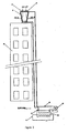
- a cooling system for a building 50 includes an enclosed circuit of refrigerant gas 52 that is passed through a condenser 54 and an evaporator 56 by a compressor 58.
- the flow of gas through the enclosed circuit 52 is controlled by an expansion valve 60.
- the evaporator includes an enclosed water circuit 62 which has thermal energy removed therefrom in order for the enclosed water circuit 62 to be used to effect cooling of the air in the building 50 in a similar manner as described previously (refer Figure 1 ).
- the condenser 54 operates as a heat exchanger to extract thermal energy from the enclosed loop of refrigerant gas 52.
- the removal of thermal energy from the enclosed loop of refrigerant gas 52 in the condenser 54 is effected by the use of another fluid, usually water, which is drawn into the condenser 54 through piping 66 and carried out of the condenser 54 through piping 68. Cooling water is drawn into the condenser 54 and passed through it under the control of pump 70. Water emitted from the condenser 54 is carried by piping 68 to the rooftop of the building 50 where it enters a rooftop mounted heat exchanger 75.
- another fluid usually water
- the heat exchanger 75 includes electrically driven fans (77 and 79) that operate to draw air therethrough.
- the piping 68 is generally thermally conductive and formed in a tortuous path with that portion formed in a tortuous path disposed in a region that will be subject to air flow as air is drawn through the heat exchanger 75.
- thermally conductive extensions may be connected to the piping 68 in order to improve the efficiency of removing thermal energy from the water in the piping 68 as air passes over the piping 68 and the thermally conductive extensions.
- thermally conductive extensions comprise heat fins formed from a suitably thermally conductive material.
- the rooftop mounted heat exchanger 75 In addition to passing cooling water through a portion of piping subject to forced airflow, the rooftop mounted heat exchanger 75 also includes moistened water absorbent material suspended over the air inlets of the heat exchangers 75 such that air drawn through the moistened water absorbent material is cooled by the action of evaporation prior to that air passing over the portion of piping 68 formed in a tortuous path. As a result of cooling air prior to passing it over piping carrying water emitted from the condenser 54, the effectiveness of removing thermal energy from that fluid is significantly increased.
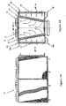
- a side view and a sectioned view of the heat exchanger 75 are provided in Figures 4A and 4B respectively.
- the heat exchanger 75 includes electrically driven fans (77 and 79) arranged to draw air through the heat exchangers 75.
- the side walls of the heat exchanger (82 and 84) comprise thermally conductive piping formed in a tortuous path carrying water from the condenser 54 the piping residing in a region subject to air flow through the heat exchanger 75.
- the thermally conductive piping is wound through a tortuous path to extend substantially over the entire region subject to airflow and in the sectional view of Figure 4B , the piping extends substantially perpendicularly into and out of the plane of the diagram.
- the side walls 82 and 84 effectively form two banks of the heat exchangers, each acting to remove thermal energy from the water passing therethrough.
- water enters the heat exchange banks 82 and 84 through inlets 68 and 68a and having passed through the respective heat exchange banks are emitted therefrom through corresponding outlets 66 and 66a.
- Water enters the heat exchange banks 82 and 84 through inlets 68 and 68a in a "hot" state and having had thermal energy extracted therefrom, the water is emitted from the heat exchange banks 82 and 84 through outlets 66 and 66a in a "cold" state.
- the inlets, 68 and 68a may be connected by a common header.
- the outlets, 66 and 66a may also be connected to a common header.
- thermal energy would be extracted from water passing through the heat exchange banks 82 and 84 solely by action of air drawn through those heat exchange banks, the efficiency of the extraction of thermal energy from water passing through the heat exchange unit is significantly improved by suspending moistened water absorbent material over the air inlets of the heat exchanger 75.
- water absorbent material pads 85 and 87 are suspended over the air inlets of the heat exchanger 75 such that air passing over the heat exchange banks 82 and 84 is required to pass through the water-absorbent material pads 85 and 87 first.
- the water absorbent material pads 85 and 87 comprise material distributed under the trademark "Celdek" and these pads 85 and 87 are continually moistened by the application of water to the top of each of the pads 85 and 87 at inlets 90 and 92. Water applied at inlets 90 and 92 eventually trickles down through the water absorbent material pads 85 and 87 substantially wetting the entire material pad. In the event that the material pads 85 and 87 do not fully absorb water applied to the inlets 90 and 92, run-off from the bottom of each pad may be collected in a tank (not detailed herein) that may be returned to the water inlets 90 and 92 via a pump (also not detailed).
- Air drawn through the material pads 85 and 87 is cooled by the action of evaporation and the passing of this cooled air over the heat exchange banks 82 and 84 acts to significantly increase the efficiency of the extraction of thermal energy from water passing through those heat exchange banks.
- a water absorbent material pad comprising a plurality of fluted apertures of a size less than 7mm in diameter is used as part of the air cooler.
- variable pitch fans are used to draw air through the primary heat exchanger and the air cooler pads.
- the use of a water absorbent material pad with apertures of a diameter less than the standard diameter results in a more efficient air cooling effect and as such, the overall size of the water absorbent material pad may be reduced whilst still providing a similar cooling effect as a pad with larger apertures.
- a reduction in overall pad size may be critical for installations where the heat exchange unit must conform to physical space restrictions. In these instances, a reduced overall pad size may result in a heat exchange unit as disclosed being a feasible option for that particular installation.
- the present invention embodies many advantages, the most significant of which being the provision of an alternative heat exchange unit that does not present a risk of generating and distributing airborne legionella bacterium that may be used to replace existing cooling tower heat exchange units.
- an alternative heat exchange unit that does not present a risk of generating and distributing airborne legionella bacterium that may be used to replace existing cooling tower heat exchange units.
- most of these approaches involve a substantial increase to the ongoing maintenance cost of the cooling system.
- the current invention maintains cooling fluid in an entirely enclosed circuit such that the cooling fluid is not exposed to the environment.
- the possibility of the cooling fluid distributing legionella bacterium into the environment in a system according to the present invention and under normal working conditions is completely eliminated.
- the arrangement of the current invention lends itself particularly well to the replacement of existing cooling tower arrangements by maintaining the use of a condenser in the basement of a building and the pumping of cooling fluid to a rooftop heat exchanger.
- the conversion of an existing cooling system arrangement incorporating a cooling tower to a system according to the present invention is relatively easily effected by the disconnection of water inlet and outlet conduits from the existing cooling tower, removal of the cooling tower and replacement therewith by a heat exchanger according to the present invention and reconnection of the fluid conduits.
Landscapes
- Engineering & Computer Science (AREA)
- Mechanical Engineering (AREA)
- General Engineering & Computer Science (AREA)
- Chemical & Material Sciences (AREA)
- Combustion & Propulsion (AREA)
- Thermal Sciences (AREA)
- Physics & Mathematics (AREA)
- Life Sciences & Earth Sciences (AREA)
- Sustainable Development (AREA)
- Heat-Exchange Devices With Radiators And Conduit Assemblies (AREA)
- Crystals, And After-Treatments Of Crystals (AREA)
- Motor Or Generator Cooling System (AREA)
- Yarns And Mechanical Finishing Of Yarns Or Ropes (AREA)
- Other Air-Conditioning Systems (AREA)
- Cooling Or The Like Of Electrical Apparatus (AREA)
Applications Claiming Priority (4)
| Application Number | Priority Date | Filing Date | Title |
|---|---|---|---|
| AUPR6332A AUPR633201A0 (en) | 2001-07-13 | 2001-07-13 | System and method of cooling |
| AUPR764401 | 2001-09-12 | ||
| AU21297/02A AU751294C (en) | 2001-07-13 | 2002-03-06 | System and method of cooling |
| EP02742532A EP1415121B1 (de) | 2001-07-13 | 2002-07-05 | Verfahren zur kühlung |
Related Parent Applications (2)
| Application Number | Title | Priority Date | Filing Date |
|---|---|---|---|
| EP02742532A Division EP1415121B1 (de) | 2001-07-13 | 2002-07-05 | Verfahren zur kühlung |
| EP02742532.1 Division | 2002-07-05 |
Publications (2)
| Publication Number | Publication Date |
|---|---|
| EP1918655A2 true EP1918655A2 (de) | 2008-05-07 |
| EP1918655A3 EP1918655A3 (de) | 2010-06-30 |
Family
ID=27152663
Family Applications (3)
| Application Number | Title | Priority Date | Filing Date |
|---|---|---|---|
| EP02742532A Revoked EP1415121B1 (de) | 2001-07-13 | 2002-07-05 | Verfahren zur kühlung |
| EP08002532.3A Withdrawn EP1921409A3 (de) | 2001-07-13 | 2002-07-05 | Kühlsystem |
| EP08001810A Withdrawn EP1918655A3 (de) | 2001-07-13 | 2002-07-05 | Kühlsystem |
Family Applications Before (2)
| Application Number | Title | Priority Date | Filing Date |
|---|---|---|---|
| EP02742532A Revoked EP1415121B1 (de) | 2001-07-13 | 2002-07-05 | Verfahren zur kühlung |
| EP08002532.3A Withdrawn EP1921409A3 (de) | 2001-07-13 | 2002-07-05 | Kühlsystem |
Country Status (11)
| Country | Link |
|---|---|
| US (2) | US20050000683A1 (de) |
| EP (3) | EP1415121B1 (de) |
| CN (1) | CN1541326B (de) |
| AT (1) | ATE386243T1 (de) |
| AU (1) | AU751294C (de) |
| DE (1) | DE60225021T2 (de) |
| DK (1) | DK1415121T3 (de) |
| ES (1) | ES2301654T3 (de) |
| NZ (1) | NZ520077A (de) |
| PT (1) | PT1415121E (de) |
| WO (1) | WO2003006908A1 (de) |
Families Citing this family (19)
| Publication number | Priority date | Publication date | Assignee | Title |
|---|---|---|---|---|
| AU2003903551A0 (en) * | 2003-07-09 | 2003-07-24 | Muller Industries Australia Pty Ltd | System and method of cooling |
| DE102006013011A1 (de) * | 2006-03-20 | 2007-09-27 | Gea Energietechnik Gmbh | Luftbeaufschlagter Kondensator |
| EP2344828B1 (de) * | 2008-09-30 | 2020-05-13 | Baltimore Aircoil Company, Inc. | Modulares kühlsystem |
| CN101496982B (zh) * | 2009-01-16 | 2012-04-18 | 尹智鸿 | 抽湿设备和抽湿系统 |
| US20130020256A1 (en) * | 2011-07-18 | 2013-01-24 | John Williams | Method for improving wastewater treatment in structures containing concentrated populations of individuals |
| US20130081414A1 (en) * | 2011-09-30 | 2013-04-04 | John D. Penton | Evaporative cooler |
| NZ631077A (en) * | 2013-07-29 | 2017-09-29 | Resmed Ltd | Heat and moisture exchanger for a patient interface |
| US10132577B2 (en) | 2014-01-20 | 2018-11-20 | Baltimore Aircoil Company, Inc. | Adiabatic refrigerant condenser controls system |
| CN105318740A (zh) * | 2015-11-12 | 2016-02-10 | 无锡市豫达换热器有限公司 | 一种采用防尘防爆技术的紧凑型换热器 |
| WO2017160346A1 (en) * | 2016-03-16 | 2017-09-21 | Inertech Ip Llc | System and methods utilizing fluid coolers and chillers to perform in-series heat rejection and trim cooling |
| EP3685112A4 (de) * | 2017-09-19 | 2021-06-16 | Evapco, Inc. | Luftgekühlte wärmeübertragungsvorrichtung mit integriertem und mechanisiertem luftvorkühlsystem |
| MX2021011322A (es) | 2019-03-19 | 2021-10-13 | Baltimore Aircoil Co Inc | Intercambiador de calor que tiene una derivacion de ensamblaje de reduccion de penacho. |
| CA3163716A1 (en) | 2019-12-11 | 2021-06-17 | Baltimore Aircoil Company, Inc. | Heat exchanger system with machine-learning based optimization |
| US11287165B2 (en) | 2020-05-20 | 2022-03-29 | Hill Phoenix, Inc. | Refrigeration system with adiabatic electrostatic cooling device |
| EP4160107A4 (de) * | 2020-05-28 | 2023-07-12 | Mitsubishi Electric Corporation | Kältekreislaufvorrichtung |
| CA3183998A1 (en) | 2020-06-23 | 2021-12-30 | Jeffrey E. Newel | Cooling system with a distribution system and a cooling unit |
| FR3112845B1 (fr) * | 2020-07-24 | 2022-08-19 | Jacir | Aérocondenseur sec ou adiabatique comprenant un système de confinement de fuites de fluide frigorigène |
| US11976882B2 (en) | 2020-11-23 | 2024-05-07 | Baltimore Aircoil Company, Inc. | Heat rejection apparatus, plume abatement system, and method |
| CN114251874B (zh) * | 2021-12-29 | 2023-10-27 | 北京华源泰盟节能设备有限公司 | 一种紧凑化余热利用系统及其余热利用方法 |
Citations (1)
| Publication number | Priority date | Publication date | Assignee | Title |
|---|---|---|---|---|
| US4182131A (en) | 1978-11-27 | 1980-01-08 | Consoli Ronald P | High efficiency air conditioner |
Family Cites Families (26)
| Publication number | Priority date | Publication date | Assignee | Title |
|---|---|---|---|---|
| US2231856A (en) * | 1938-08-13 | 1941-02-11 | Pauline L Wetter | Refrigerating apparatus |
| US2518760A (en) * | 1945-11-13 | 1950-08-15 | Fluor Corp | Air-cooled heat exchanger |
| US2636371A (en) * | 1950-04-03 | 1953-04-28 | Fluor Corp | Mechanical draft water cooling tower |
| US2655795A (en) * | 1952-01-02 | 1953-10-20 | Dyer John | Refrigerator condensing unit cooler |
| US2661933A (en) * | 1952-02-25 | 1953-12-08 | Niagara Blower Co | Evaporative cooler for condensing hot compressed gas |
| US3384165A (en) * | 1966-02-03 | 1968-05-21 | Du Pont | Heat exchanger |
| US3630271A (en) * | 1970-07-06 | 1971-12-28 | American Standard Inc | Heat storage device using fusible material |
| US3995689A (en) * | 1975-01-27 | 1976-12-07 | The Marley Cooling Tower Company | Air cooled atmospheric heat exchanger |
| US3984995A (en) * | 1975-03-12 | 1976-10-12 | Starr Robert H | Method and apparatus for the treatment of air |
| US4315873A (en) * | 1977-11-21 | 1982-02-16 | Hudson Products Corporation | Cooling equipment |
| US4204409A (en) * | 1978-07-26 | 1980-05-27 | Satama Kauko K | Air conditioning apparatus and system |
| US4562015A (en) * | 1984-05-22 | 1985-12-31 | The Munters Corporation | Open mesh fill assembly |
| US4637225A (en) * | 1985-11-12 | 1987-01-20 | Marshall Ralph C | Air conditioning apparatus |
| US4815298A (en) * | 1986-05-06 | 1989-03-28 | Steenburgh Jr Leon C Van | Refrigeration system with bypass valves |
| CA2016690C (en) * | 1989-06-07 | 1994-03-08 | William T. Osborne | Cooling system with supplemental thermal storage |
| US5076065A (en) * | 1990-12-20 | 1991-12-31 | Aztec Sensible Cooling, Inc. | High saturation efficiency indirect and indirect/direct evaporative cooling process and apparatus |
| ATE153319T1 (de) * | 1992-07-23 | 1997-06-15 | Unilever Nv | Verfahren und vorrichtung zur überwachung von mikroorganismen |
| US5555742A (en) * | 1993-07-12 | 1996-09-17 | Kelley; Franklyn F. | Evaporative cooler with scrubber and enthalpic heating system |
| US5453207A (en) * | 1993-11-01 | 1995-09-26 | Simpson; Gregory D. | Biocide treatment system and method |
| DE4423960A1 (de) * | 1994-07-07 | 1996-01-11 | Martin Gabler | Vorrichtung zum Kühlen einer zirkulierenden Wärmeträgerflüssigkeit |
| US5775580A (en) * | 1995-07-20 | 1998-07-07 | Sizemore; Timothy J. | Evaporative cooling system |
| US5600960A (en) * | 1995-11-28 | 1997-02-11 | American Standard Inc. | Near optimization of cooling tower condenser water |
| NL1007346C2 (nl) * | 1997-10-23 | 1999-05-04 | Doomernik Ice B V | Werkwijze voor het bedrijven van een koelinrichting en een koelinrichting. |
| SE9802463D0 (sv) * | 1997-12-22 | 1998-07-08 | Munters Ab | Air treatment unit |
| JP2001165581A (ja) * | 1999-12-06 | 2001-06-22 | Takenaka Komuten Co Ltd | 空気熱交換器の流動空気冷却装置 |
| US6539732B2 (en) * | 2000-02-22 | 2003-04-01 | E-Pak Technology, Inc. | Refrigeration system and method of operation therefor |
-
2002
- 2002-03-06 AU AU21297/02A patent/AU751294C/en not_active Expired
- 2002-07-05 PT PT02742532T patent/PT1415121E/pt unknown
- 2002-07-05 AT AT02742532T patent/ATE386243T1/de active
- 2002-07-05 EP EP02742532A patent/EP1415121B1/de not_active Revoked
- 2002-07-05 US US10/483,656 patent/US20050000683A1/en not_active Abandoned
- 2002-07-05 DE DE60225021T patent/DE60225021T2/de not_active Expired - Lifetime
- 2002-07-05 DK DK02742532T patent/DK1415121T3/da active
- 2002-07-05 EP EP08002532.3A patent/EP1921409A3/de not_active Withdrawn
- 2002-07-05 CN CN028158350A patent/CN1541326B/zh not_active Expired - Lifetime
- 2002-07-05 EP EP08001810A patent/EP1918655A3/de not_active Withdrawn
- 2002-07-05 ES ES02742532T patent/ES2301654T3/es not_active Expired - Lifetime
- 2002-07-05 WO PCT/AU2002/000898 patent/WO2003006908A1/en not_active Ceased
- 2002-07-09 NZ NZ520077A patent/NZ520077A/en not_active IP Right Cessation
-
2008
- 2008-01-31 US US12/023,182 patent/US20080115921A1/en not_active Abandoned
Patent Citations (1)
| Publication number | Priority date | Publication date | Assignee | Title |
|---|---|---|---|---|
| US4182131A (en) | 1978-11-27 | 1980-01-08 | Consoli Ronald P | High efficiency air conditioner |
Also Published As
| Publication number | Publication date |
|---|---|
| US20050000683A1 (en) | 2005-01-06 |
| EP1918655A3 (de) | 2010-06-30 |
| ES2301654T3 (es) | 2008-07-01 |
| EP1415121A1 (de) | 2004-05-06 |
| CN1541326A (zh) | 2004-10-27 |
| PT1415121E (pt) | 2008-05-16 |
| AU751294B1 (en) | 2002-08-08 |
| EP1415121B1 (de) | 2008-02-13 |
| ATE386243T1 (de) | 2008-03-15 |
| WO2003006908A1 (en) | 2003-01-23 |
| DE60225021T2 (de) | 2009-02-12 |
| EP1921409A3 (de) | 2014-06-11 |
| EP1415121A4 (de) | 2004-10-13 |
| DE60225021D1 (de) | 2008-03-27 |
| NZ520077A (en) | 2003-11-28 |
| EP1921409A2 (de) | 2008-05-14 |
| US20080115921A1 (en) | 2008-05-22 |
| DK1415121T3 (da) | 2008-06-16 |
| CN1541326B (zh) | 2011-01-19 |
| AU751294C (en) | 2005-04-07 |
Similar Documents
| Publication | Publication Date | Title |
|---|---|---|
| US20080115921A1 (en) | System and method of cooling | |
| WO2005005905A1 (en) | System and method of cooling | |
| EP2150764B1 (de) | Kühlsystem | |
| EP2344828B1 (de) | Modulares kühlsystem | |
| CA2863401C (en) | Air-to-air heat exchanger bypass for wet cooling tower apparatus and method | |
| US20090301114A1 (en) | Heat exchange apparatus | |
| RU2125209C1 (ru) | Устройство для охлаждения поступающего воздуха в установке кондиционирования воздуха | |
| CN101285606A (zh) | 冷却系统和方法 |
Legal Events
| Date | Code | Title | Description |
|---|---|---|---|
| PUAI | Public reference made under article 153(3) epc to a published international application that has entered the european phase |
Free format text: ORIGINAL CODE: 0009012 |
|
| 17P | Request for examination filed |
Effective date: 20080229 |
|
| AC | Divisional application: reference to earlier application |
Ref document number: 1415121 Country of ref document: EP Kind code of ref document: P |
|
| AK | Designated contracting states |
Kind code of ref document: A2 Designated state(s): AT BE BG CH CY CZ DE DK EE ES FI FR GB GR IE IT LI LU MC NL PT SE SK TR |
|
| RIN1 | Information on inventor provided before grant (corrected) |
Inventor name: WADOWSKI, TOMEK TADEUSZ Inventor name: LEAMON, ROBERT JAMES Inventor name: HALL, GRANT DAVID |
|
| PUAL | Search report despatched |
Free format text: ORIGINAL CODE: 0009013 |
|
| AK | Designated contracting states |
Kind code of ref document: A3 Designated state(s): AT BE BG CH CY CZ DE DK EE ES FI FR GB GR IE IT LI LU MC NL PT SE SK TR |
|
| RIC1 | Information provided on ipc code assigned before grant |
Ipc: F28B 1/06 20060101ALI20100527BHEP Ipc: F28D 5/00 20060101AFI20100527BHEP Ipc: F24F 3/06 20060101ALI20100527BHEP Ipc: F24F 6/04 20060101ALI20100527BHEP Ipc: F24F 5/00 20060101ALI20100527BHEP Ipc: F28D 5/02 20060101ALI20100527BHEP |
|
| AKX | Designation fees paid |
Designated state(s): AT BE BG CH CY CZ DE DK EE ES FI FR GB GR IE IT LI LU MC NL PT SE SK TR |
|
| 17Q | First examination report despatched |
Effective date: 20120604 |
|
| STAA | Information on the status of an ep patent application or granted ep patent |
Free format text: STATUS: THE APPLICATION IS DEEMED TO BE WITHDRAWN |
|
| 18D | Application deemed to be withdrawn |
Effective date: 20121016 |