EP1918634A1 - Device for providing lighting along a ground surface - Google Patents
Device for providing lighting along a ground surface Download PDFInfo
- Publication number
- EP1918634A1 EP1918634A1 EP07020987A EP07020987A EP1918634A1 EP 1918634 A1 EP1918634 A1 EP 1918634A1 EP 07020987 A EP07020987 A EP 07020987A EP 07020987 A EP07020987 A EP 07020987A EP 1918634 A1 EP1918634 A1 EP 1918634A1
- Authority
- EP
- European Patent Office
- Prior art keywords
- light source
- ground surface
- light
- reflector
- lateral
- Prior art date
- Legal status (The legal status is an assumption and is not a legal conclusion. Google has not performed a legal analysis and makes no representation as to the accuracy of the status listed.)
- Withdrawn
Links
Images


Classifications
-
- F—MECHANICAL ENGINEERING; LIGHTING; HEATING; WEAPONS; BLASTING
- F21—LIGHTING
- F21S—NON-PORTABLE LIGHTING DEVICES; SYSTEMS THEREOF; VEHICLE LIGHTING DEVICES SPECIALLY ADAPTED FOR VEHICLE EXTERIORS
- F21S9/00—Lighting devices with a built-in power supply; Systems employing lighting devices with a built-in power supply
- F21S9/02—Lighting devices with a built-in power supply; Systems employing lighting devices with a built-in power supply the power supply being a battery or accumulator
- F21S9/03—Lighting devices with a built-in power supply; Systems employing lighting devices with a built-in power supply the power supply being a battery or accumulator rechargeable by exposure to light
- F21S9/037—Lighting devices with a built-in power supply; Systems employing lighting devices with a built-in power supply the power supply being a battery or accumulator rechargeable by exposure to light the solar unit and the lighting unit being located within or on the same housing
-
- F—MECHANICAL ENGINEERING; LIGHTING; HEATING; WEAPONS; BLASTING
- F21—LIGHTING
- F21S—NON-PORTABLE LIGHTING DEVICES; SYSTEMS THEREOF; VEHICLE LIGHTING DEVICES SPECIALLY ADAPTED FOR VEHICLE EXTERIORS
- F21S8/00—Lighting devices intended for fixed installation
- F21S8/08—Lighting devices intended for fixed installation with a standard
- F21S8/081—Lighting devices intended for fixed installation with a standard of low-built type, e.g. landscape light
- F21S8/083—Lighting devices intended for fixed installation with a standard of low-built type, e.g. landscape light of bollard type, i.e. with lighting fixture integrated into the standard or mounted on top of it and having substantially the same diameter
-
- F—MECHANICAL ENGINEERING; LIGHTING; HEATING; WEAPONS; BLASTING
- F21—LIGHTING
- F21V—FUNCTIONAL FEATURES OR DETAILS OF LIGHTING DEVICES OR SYSTEMS THEREOF; STRUCTURAL COMBINATIONS OF LIGHTING DEVICES WITH OTHER ARTICLES, NOT OTHERWISE PROVIDED FOR
- F21V11/00—Screens not covered by groups F21V1/00, F21V3/00, F21V7/00 or F21V9/00
- F21V11/08—Screens not covered by groups F21V1/00, F21V3/00, F21V7/00 or F21V9/00 using diaphragms containing one or more apertures
- F21V11/14—Screens not covered by groups F21V1/00, F21V3/00, F21V7/00 or F21V9/00 using diaphragms containing one or more apertures with many small apertures
-
- F—MECHANICAL ENGINEERING; LIGHTING; HEATING; WEAPONS; BLASTING
- F21—LIGHTING
- F21V—FUNCTIONAL FEATURES OR DETAILS OF LIGHTING DEVICES OR SYSTEMS THEREOF; STRUCTURAL COMBINATIONS OF LIGHTING DEVICES WITH OTHER ARTICLES, NOT OTHERWISE PROVIDED FOR
- F21V7/00—Reflectors for light sources
- F21V7/0008—Reflectors for light sources providing for indirect lighting
- F21V7/0016—Reflectors for light sources providing for indirect lighting on lighting devices that also provide for direct lighting, e.g. by means of independent light sources, by splitting of the light beam, by switching between both lighting modes
-
- F—MECHANICAL ENGINEERING; LIGHTING; HEATING; WEAPONS; BLASTING
- F21—LIGHTING
- F21V—FUNCTIONAL FEATURES OR DETAILS OF LIGHTING DEVICES OR SYSTEMS THEREOF; STRUCTURAL COMBINATIONS OF LIGHTING DEVICES WITH OTHER ARTICLES, NOT OTHERWISE PROVIDED FOR
- F21V7/00—Reflectors for light sources
- F21V7/04—Optical design
- F21V7/09—Optical design with a combination of different curvatures
-
- F—MECHANICAL ENGINEERING; LIGHTING; HEATING; WEAPONS; BLASTING
- F21—LIGHTING
- F21V—FUNCTIONAL FEATURES OR DETAILS OF LIGHTING DEVICES OR SYSTEMS THEREOF; STRUCTURAL COMBINATIONS OF LIGHTING DEVICES WITH OTHER ARTICLES, NOT OTHERWISE PROVIDED FOR
- F21V9/00—Elements for modifying spectral properties, polarisation or intensity of the light emitted, e.g. filters
- F21V9/08—Elements for modifying spectral properties, polarisation or intensity of the light emitted, e.g. filters for producing coloured light, e.g. monochromatic; for reducing intensity of light
-
- F—MECHANICAL ENGINEERING; LIGHTING; HEATING; WEAPONS; BLASTING
- F21—LIGHTING
- F21W—INDEXING SCHEME ASSOCIATED WITH SUBCLASSES F21K, F21L, F21S and F21V, RELATING TO USES OR APPLICATIONS OF LIGHTING DEVICES OR SYSTEMS
- F21W2111/00—Use or application of lighting devices or systems for signalling, marking or indicating, not provided for in codes F21W2102/00 – F21W2107/00
- F21W2111/02—Use or application of lighting devices or systems for signalling, marking or indicating, not provided for in codes F21W2102/00 – F21W2107/00 for roads, paths or the like
-
- F—MECHANICAL ENGINEERING; LIGHTING; HEATING; WEAPONS; BLASTING
- F21—LIGHTING
- F21W—INDEXING SCHEME ASSOCIATED WITH SUBCLASSES F21K, F21L, F21S and F21V, RELATING TO USES OR APPLICATIONS OF LIGHTING DEVICES OR SYSTEMS
- F21W2131/00—Use or application of lighting devices or systems not provided for in codes F21W2102/00-F21W2121/00
- F21W2131/10—Outdoor lighting
- F21W2131/103—Outdoor lighting of streets or roads
-
- F—MECHANICAL ENGINEERING; LIGHTING; HEATING; WEAPONS; BLASTING
- F21—LIGHTING
- F21W—INDEXING SCHEME ASSOCIATED WITH SUBCLASSES F21K, F21L, F21S and F21V, RELATING TO USES OR APPLICATIONS OF LIGHTING DEVICES OR SYSTEMS
- F21W2131/00—Use or application of lighting devices or systems not provided for in codes F21W2102/00-F21W2121/00
- F21W2131/10—Outdoor lighting
- F21W2131/105—Outdoor lighting of arenas or the like
-
- F—MECHANICAL ENGINEERING; LIGHTING; HEATING; WEAPONS; BLASTING
- F21—LIGHTING
- F21W—INDEXING SCHEME ASSOCIATED WITH SUBCLASSES F21K, F21L, F21S and F21V, RELATING TO USES OR APPLICATIONS OF LIGHTING DEVICES OR SYSTEMS
- F21W2131/00—Use or application of lighting devices or systems not provided for in codes F21W2102/00-F21W2121/00
- F21W2131/10—Outdoor lighting
- F21W2131/109—Outdoor lighting of gardens
-
- F—MECHANICAL ENGINEERING; LIGHTING; HEATING; WEAPONS; BLASTING
- F21—LIGHTING
- F21Y—INDEXING SCHEME ASSOCIATED WITH SUBCLASSES F21K, F21L, F21S and F21V, RELATING TO THE FORM OR THE KIND OF THE LIGHT SOURCES OR OF THE COLOUR OF THE LIGHT EMITTED
- F21Y2115/00—Light-generating elements of semiconductor light sources
- F21Y2115/10—Light-emitting diodes [LED]
-
- Y—GENERAL TAGGING OF NEW TECHNOLOGICAL DEVELOPMENTS; GENERAL TAGGING OF CROSS-SECTIONAL TECHNOLOGIES SPANNING OVER SEVERAL SECTIONS OF THE IPC; TECHNICAL SUBJECTS COVERED BY FORMER USPC CROSS-REFERENCE ART COLLECTIONS [XRACs] AND DIGESTS
- Y02—TECHNOLOGIES OR APPLICATIONS FOR MITIGATION OR ADAPTATION AGAINST CLIMATE CHANGE
- Y02B—CLIMATE CHANGE MITIGATION TECHNOLOGIES RELATED TO BUILDINGS, e.g. HOUSING, HOUSE APPLIANCES OR RELATED END-USER APPLICATIONS
- Y02B20/00—Energy efficient lighting technologies, e.g. halogen lamps or gas discharge lamps
- Y02B20/72—Energy efficient lighting technologies, e.g. halogen lamps or gas discharge lamps in street lighting
Definitions
- the present invention relates to a device for providing lighting along a ground surface.
- the invention in particular relates to providing lighting along paths and the like.
- lampposts As night lighting along motorways, bicycle paths and/or footpaths, for example.
- Such night lighting causes ecological damage, also referred to as light pollution.
- Said light pollution disturbs the biological day and night rhythm of people and animals and affects the growth of plants.
- said light pollution appears to interfere with astronomical observations. Because of the above drawbacks, more and more people want to have public lighting in rural areas removed completely. A drawback of such a measure would be that traffic safety would decrease, whilst in addition the social sense of security would be affected by such a measure.
- Patent publication BE-A-1 014 501 discloses a lighting device also referred to as "downlight", which is used for accent lighting, which causes a specific object in a museum, for example, to stand out because it is lit in a special way. Inside the lighting device, light rays from a light source are reflected a large number of times before lighting the object in question.
- German utility model DE 297 18 936 U1 describes marking lighting, in which use is made of a semicylindrical housing and a semicylindrical diffusor, both having an open bottom side.
- the object of the present invention is to provide a device for providing lighting along a ground surface which might constitute an alternative in particular for the public lighting in rural areas by means of lampposts.
- the device according to the invention comprises a light source and at least one concave lateral reflector disposed beside the light source for reflecting light rays directly incident thereon from the light source past said light source so as to thus form a light beam of reflected light rays extending from said lateral reflector at least substantially in horizontal direction along the ground surface, and a support attached to the ground surface for positioning the light source and said at least one lateral reflector above the ground surface to be lit.
- Said at least one light beam which can be emitted by the device according to the invention is very suitable for use as a beacon, with the light beam being directed in the longitudinal direction of a road or a path.
- Road users will thus be able to see the course of the road far in advance, whilst the extent of light pollution can be minimised.
- the above phrase "at least substantially in horizontal direction" is to be understood to include in any case the situation in which the devices are used on an inclined ground surface and said at least one light beam is directed parallel to said inclined ground surface.
- the device is provided with two concave lateral reflectors disposed opposite each other on either side of the light source for reflecting light rays directly incident thereon from the light source in a direction towards each other so as to thus form two light beams of reflected light rays extending from the respective lateral reflectors at least substantially in two opposite, at least substantially horizontal directions along the ground surface.
- This enables the device according to the invention to perform the "beacon" function even better by emitting light beams in two opposite directions along a road or a path.
- said at least one lateral reflector is provided with holes for passing through part of the light rays directed to said at least one lateral reflector.
- Reflected light rays can pass the holes to form a light beam beyond the lateral reflector in question.
- the device In order to be able to indicate by means of colours on which side of a road/path the device is disposed in dependence on the direction in which a (road) user approaches the device, it is preferable if the device is provided with a coloured filter element for colouring one light beam.
- Said at least one lateral reflector is preferably of the parabolic type, which makes it possible to create a parallel, slightly diverging or slightly converging light beam, which is advantageous from the viewpoint of the "beacon" function.
- the device according to the invention is preferably further provided with a concave main reflector on the side of the light source remote from the ground surface for reflecting light rays from the light source past the light source so as to thus form a vision beam of reflected light rays downwards onto the ground surface.
- the vision beam will thus contribute to marking a road or a path.
- at least part of the ground surface is also directly lighted, so that unevennesses therein, for example, will be better visible.
- the main reflector is preferably so positioned relative to a light source and/or so configured that the vision beam is directed obliquely downwards to the ground surface.
- the direction of a light beam or a vision beam is determined by the central axis of the beam in question.
- the device can be disposed beside a road or a path, and the extent of light pollution is furthermore reduced as much as possible.
- a well-directed vision beam can be obtained in particular if the main reflector is of the parabolic type, in which case the main reflector is furthermore preferably built up of a number of contiguous parabolic segments and/or the main reflector is concave in two perpendicular planes.
- the light source comprises an LED, on the one hand because of the low energy consumption and comparatively low purchasing and operating costs thereof, and on the other hand because of the fact that the LED can be regarded as a pointed light source, so that also said at least one light beam from said at least one lateral reflector and the vision beam from the main reflector can be clearly defined.
- the device comprises a solar cell for supplying electric power to the light source, or at least to an electric accumulator connected to the light source. In this way it is no longer necessary to install electric power supply lines in the ground for supplying electric power to the light source.
- the extent of light pollution is in particular reduced if the support is arranged for positioning the light source at a height of maximally 200 cm above the ground surface. Such a height is significantly lower than the comparable height when lampposts according to the prior art are used.
- the support preferably comprises a post that can be attached to the ground, which attachment can be realised, for example, by driving the post into the ground.
- another preferred embodiment of a device according to the invention is characterised in that said at least one lateral reflector is of the partially light-transmitting type.
- a lateral reflector may be considered whose entire surface is so configured that said at least one reflector reflects only part of the light rays whilst transmitting another part of the light rays.
- one part of the surface of said at least one lateral reflector reflects light rays and another part of the surface of said at least one lateral reflector transmits light rays.
- the device is provided with at least three concave lateral reflectors so as to thus form at least three light beams of reflected light rays at least substantially in horizontal direction along the ground surface.
- the invention further relates to a combination of a number of devices according to the invention as described in the foregoing, in which light beams from the devices are at least substantially aligned so as to mark a path.
- a path may be a bicycle path or a footpath, for example, along which devices according to the invention are positioned.
- Said path may be a rectilinear path or a curvilinear path.
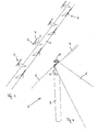
- Figure 1 shows a path 1, such as a footpath or a bicycle path.
- Lighting posts 2 are disposed in diametrically opposite positions on either side of the path 1, which lighting posts each form a preferred embodiment of the device according to the invention.
- FIG. 2 shows the lighting post in more detail.
- the lighting post 2 is essentially built up of a support post 3 driven into the ground beside the path 1, on which a lighting head 4 is mounted, which lighting head will be explained in more detail yet with reference to the next figures.
- a vision beam 5 is emitted obliquely downwards onto the path 1, as are two light beams 6, 7 directed in opposite directions, which light beams 6, 7 are each oriented at least substantially horizontally and parallel to the path 1.
- a typical suitable height of the lighting posts 2 is such that the light source 11 (yet to be discussed) therein will be positioned at a height of about 100 cm above the level of the path 1.
- FIGS 3-5b show various views of the lighting head 4.
- the lighting head 4 comprises an LED 11 as the light source, which is mounted to an inclined bar-like LED holder 12.
- the LED 11 thus has an upwardly inclined orientation, with the central axis of the light rays emitted by the LED 11 being directed obliquely upwards away from the path 1.
- Lateral reflectors 13, 14 are provided at the front side and the rear side, seen in the longitudinal direction of the path 1. The LED 11 is positioned between the lateral reflectors 13, 14.
- the lateral reflectors are concave, with the concave longitudinal edges 15, 16 (only shown for the lateral reflector 14 in figure 3) converging into points 17, 18, so that the shape of the lateral reflectors 13, 14 can be compared to that of a piece of orange peel.
- the lateral reflectors 13, 14 are provided with rows of holes 19.
- the light rays from the LED 11 directed sideways in the longitudinal direction of the path 1 will be reflected by the concave lateral reflectors 13, 14, as a result of which the reflected light rays will be directed at least substantially parallel to each other to the other one of the lateral reflectors 13, 14.
- a significant part of the reflected light rays will pass through the holes 19 of the other lateral reflector 13, 14 and form the respective light beams 6, 7 beyond the lateral reflector 13, 14.
- the lighting head 4 further comprises a concave, dish-shaped main reflector 20 positioned directly opposite the LED 11.
- the main reflector 20 is of the parabolic type or is at least built up of a number of parabolic segments, which blend together almost seamlessly. Reflection of light rays from the LED 11 by the main reflector 20 leads to the formation of the vision beam 5. Within the framework of the present invention, the use of the main reflector 20 is to be considered optional.
- the lighting head 4 further comprises a housing 21, via which the LED holder 12 with the LED 11, the lateral reflectors 13, 14 and the main reflector 20 are connected to the support post 3.
- the shape of the housing 21 with the concave side 22 is such that it does not disturb the vision beam 5, or at least that the shape of the vision beam 5 is thus optimally geared to its function.
- the lighting head 4 further comprises a transparent cylindrical window 23 at the outer side, which functions to protect the interior of the lighting head 4, as well as a transparent cover 24.
- a solar cell 25 is provided under said cover 24 (see figure 2) for supplying electric power to the LED 11 via an electric accumulator (not shown), which is likewise accommodated in the lighting head 4.
- the solar cell 25 can also function as a light sensor for controlling electronics for turning the LED 11 on and off. Detections made by the solar cell 25 can also be used for controlling the extent to which electric power is to be supplied to the LED by the electric accumulator.
Abstract
The present invention provides a device for providing lighting along a ground surface, comprising a light source (11) and at least one concave lateral reflector (13,14) disposed beside the light source (11) for reflecting light rays directly incident thereon from the light source (11) past said light source (11) so as to thus form a light beam of reflected light rays extending from said lateral reflector (13,14) at least substantially in horizontal direction along the ground surface, and a support (3) attached to the ground surface for positioning the light source (11) and said at least one lateral reflector (13,14) above the ground surface to be lit.
Description
- The present invention relates to a device for providing lighting along a ground surface. The invention in particular relates to providing lighting along paths and the like.
- It is known to use lampposts as night lighting along motorways, bicycle paths and/or footpaths, for example. Such night lighting causes ecological damage, also referred to as light pollution. Said light pollution disturbs the biological day and night rhythm of people and animals and affects the growth of plants. Furthermore, said light pollution appears to interfere with astronomical observations. Because of the above drawbacks, more and more people want to have public lighting in rural areas removed completely. A drawback of such a measure would be that traffic safety would decrease, whilst in addition the social sense of security would be affected by such a measure.
- Patent publication
BE-A-1 014 501 -
German utility model DE 297 18 936 U1 describes marking lighting, in which use is made of a semicylindrical housing and a semicylindrical diffusor, both having an open bottom side. - The object of the present invention is to provide a device for providing lighting along a ground surface which might constitute an alternative in particular for the public lighting in rural areas by means of lampposts. In order to accomplish that object, the device according to the invention comprises a light source and at least one concave lateral reflector disposed beside the light source for reflecting light rays directly incident thereon from the light source past said light source so as to thus form a light beam of reflected light rays extending from said lateral reflector at least substantially in horizontal direction along the ground surface, and a support attached to the ground surface for positioning the light source and said at least one lateral reflector above the ground surface to be lit. Said at least one light beam which can be emitted by the device according to the invention is very suitable for use as a beacon, with the light beam being directed in the longitudinal direction of a road or a path. Road users will thus be able to see the course of the road far in advance, whilst the extent of light pollution can be minimised. The above phrase "at least substantially in horizontal direction" is to be understood to include in any case the situation in which the devices are used on an inclined ground surface and said at least one light beam is directed parallel to said inclined ground surface.
- Quite preferably, the device is provided with two concave lateral reflectors disposed opposite each other on either side of the light source for reflecting light rays directly incident thereon from the light source in a direction towards each other so as to thus form two light beams of reflected light rays extending from the respective lateral reflectors at least substantially in two opposite, at least substantially horizontal directions along the ground surface. This enables the device according to the invention to perform the "beacon" function even better by emitting light beams in two opposite directions along a road or a path.
- In particular when two opposite concave lateral reflectors according to the above-discussed preferred embodiments are used, it is furthermore preferable if said at least one lateral reflector is provided with holes for passing through part of the light rays directed to said at least one lateral reflector. Thus it is possible to actually have the light beams shine in horizontal direction, because the lateral reflectors are not in the way of said light beams, as it were. Reflected light rays can pass the holes to form a light beam beyond the lateral reflector in question.
- In order to be able to indicate by means of colours on which side of a road/path the device is disposed in dependence on the direction in which a (road) user approaches the device, it is preferable if the device is provided with a coloured filter element for colouring one light beam.
- Said at least one lateral reflector is preferably of the parabolic type, which makes it possible to create a parallel, slightly diverging or slightly converging light beam, which is advantageous from the viewpoint of the "beacon" function.
- In addition to said at least one lateral reflector, the device according to the invention is preferably further provided with a concave main reflector on the side of the light source remote from the ground surface for reflecting light rays from the light source past the light source so as to thus form a vision beam of reflected light rays downwards onto the ground surface. The vision beam will thus contribute to marking a road or a path. In addition, at least part of the ground surface is also directly lighted, so that unevennesses therein, for example, will be better visible.
- The main reflector is preferably so positioned relative to a light source and/or so configured that the vision beam is directed obliquely downwards to the ground surface. The direction of a light beam or a vision beam is determined by the central axis of the beam in question. Thus the device can be disposed beside a road or a path, and the extent of light pollution is furthermore reduced as much as possible.
- A well-directed vision beam can be obtained in particular if the main reflector is of the parabolic type, in which case the main reflector is furthermore preferably built up of a number of contiguous parabolic segments and/or the main reflector is concave in two perpendicular planes.
- Quite preferably, the light source comprises an LED, on the one hand because of the low energy consumption and comparatively low purchasing and operating costs thereof, and on the other hand because of the fact that the LED can be regarded as a pointed light source, so that also said at least one light beam from said at least one lateral reflector and the vision beam from the main reflector can be clearly defined.
- Especially in combination with the preceding preferred embodiment, in which the light source comprises an LED, it is furthermore preferable if the device comprises a solar cell for supplying electric power to the light source, or at least to an electric accumulator connected to the light source. In this way it is no longer necessary to install electric power supply lines in the ground for supplying electric power to the light source.
- The extent of light pollution is in particular reduced if the support is arranged for positioning the light source at a height of maximally 200 cm above the ground surface. Such a height is significantly lower than the comparable height when lampposts according to the prior art are used.
- The support preferably comprises a post that can be attached to the ground, which attachment can be realised, for example, by driving the post into the ground.
- In particular as an alternative to the use of holes according to a preferred embodiment as discussed in the foregoing, but possibly even in combination therewith, another preferred embodiment of a device according to the invention is characterised in that said at least one lateral reflector is of the partially light-transmitting type. In this connection a lateral reflector may be considered whose entire surface is so configured that said at least one reflector reflects only part of the light rays whilst transmitting another part of the light rays. According to another preferred embodiment it is alternatively also possible within the framework of the present invention that one part of the surface of said at least one lateral reflector reflects light rays and another part of the surface of said at least one lateral reflector transmits light rays.
- In particular for use at locations where a number of roads/paths converge, for example at a junction or a crossing, it is preferable if the device is provided with at least three concave lateral reflectors so as to thus form at least three light beams of reflected light rays at least substantially in horizontal direction along the ground surface.
- The invention further relates to a combination of a number of devices according to the invention as described in the foregoing, in which light beams from the devices are at least substantially aligned so as to mark a path. Such a path may be a bicycle path or a footpath, for example, along which devices according to the invention are positioned. Said path may be a rectilinear path or a curvilinear path.
- The invention will be explained in more detail hereinafter by means of a description of a preferred embodiment of a device according to the invention.
- Figure 1 schematically shows a path beside which a preferred embodiment of the device according to the invention is disposed;
- Figure 2 shows a single device;
- Figure 3 is a perspective view of the lighting head of the device according to the invention;
- Figure 4 is a transparent side view of the lighting head; and
- Figures 5a and 5b are sectional views along the lines A-A and B-B, respectively, in figure 4.
- Figure 1 shows a path 1, such as a footpath or a bicycle path.
Lighting posts 2 are disposed in diametrically opposite positions on either side of the path 1, which lighting posts each form a preferred embodiment of the device according to the invention. - Figure 2 shows the lighting post in more detail. The
lighting post 2 is essentially built up of asupport post 3 driven into the ground beside the path 1, on which alighting head 4 is mounted, which lighting head will be explained in more detail yet with reference to the next figures. From thelighting head 4, avision beam 5 is emitted obliquely downwards onto the path 1, as are twolight beams 6, 7 directed in opposite directions, whichlight beams 6, 7 are each oriented at least substantially horizontally and parallel to the path 1. As a result, people who use the path 1 during the night can easily see thelight beams 6, 7 from a comparatively large distance, whilst the light pollution caused by thelight beams 6, 7 is minimal. The same applies to thevision beam 5, because of the specific direction of this vision beam on the one hand and the limited height of thelighting posts 2 on the other hand. A typical suitable height of thelighting posts 2 is such that the light source 11 (yet to be discussed) therein will be positioned at a height of about 100 cm above the level of the path 1. - Figures 3-5b show various views of the
lighting head 4. Thelighting head 4 comprises anLED 11 as the light source, which is mounted to an inclined bar-like LED holder 12. TheLED 11 thus has an upwardly inclined orientation, with the central axis of the light rays emitted by theLED 11 being directed obliquely upwards away from the path 1.Lateral reflectors LED 11 is positioned between thelateral reflectors longitudinal edges 15, 16 (only shown for thelateral reflector 14 in figure 3) converging intopoints 17, 18, so that the shape of thelateral reflectors lateral reflectors holes 19. - The light rays from the
LED 11 directed sideways in the longitudinal direction of the path 1 will be reflected by the concavelateral reflectors lateral reflectors holes 19 of the otherlateral reflector respective light beams 6, 7 beyond thelateral reflector - In an alternative embodiment it would also be possible to leave out the
holes 19 and uselateral reflectors holes 19 are shown in figure 3, but rather make said parts transparent, which can be realised by providing a reflective layer, for example by means of a suitable vapour deposition process. It is also possible to make the reflector area both reflective as well as transparent over the entire area thereof. - In addition to the
lateral reflectors lighting head 4 further comprises a concave, dish-shapedmain reflector 20 positioned directly opposite theLED 11. Themain reflector 20 is of the parabolic type or is at least built up of a number of parabolic segments, which blend together almost seamlessly. Reflection of light rays from theLED 11 by themain reflector 20 leads to the formation of thevision beam 5. Within the framework of the present invention, the use of themain reflector 20 is to be considered optional. - The
lighting head 4 further comprises ahousing 21, via which theLED holder 12 with theLED 11, thelateral reflectors main reflector 20 are connected to thesupport post 3. The shape of thehousing 21 with theconcave side 22 is such that it does not disturb thevision beam 5, or at least that the shape of thevision beam 5 is thus optimally geared to its function. - The
lighting head 4 further comprises a transparentcylindrical window 23 at the outer side, which functions to protect the interior of thelighting head 4, as well as atransparent cover 24. Asolar cell 25 is provided under said cover 24 (see figure 2) for supplying electric power to theLED 11 via an electric accumulator (not shown), which is likewise accommodated in thelighting head 4. Thesolar cell 25 can also function as a light sensor for controlling electronics for turning theLED 11 on and off. Detections made by thesolar cell 25 can also be used for controlling the extent to which electric power is to be supplied to the LED by the electric accumulator. - Various variants to the preferred embodiment described in the foregoing are possible within the scope of the present invention. Thus it is possible, for example, to use four lateral reflectors instead of two, which reflectors are arranged in a horizontal plane, each in a quadrant, around an upwardly directed light source. In this way four light beams are formed, which extend in the direction of the paths that converge at a crossing.
Claims (18)
- A device for providing lighting along a ground surface, comprising a light source and at least one concave lateral reflector disposed beside the light source for reflecting light rays directly incident thereon from the light source past said light source so as to thus form a light beam of reflected light rays extending from said lateral reflector at least substantially in horizontal direction along the ground surface, and a support attached to the ground surface for positioning the light source and said at least one lateral reflector above the ground surface to be lit.
- A device according to claim 1, characterised in that the device is provided with two concave lateral reflectors disposed opposite each other on either side of the light source for reflecting light rays directly incident thereon from the light source in a direction towards each other so as to thus form two light beams of reflected light rays extending from the respective lateral reflectors at least substantially in two opposite, at least substantially horizontal directions along the ground surface.
- A device according to claim 1 or 2, characterised in that said at least one lateral reflector is provided with holes for passing through part of the light rays directed at said at least one lateral reflector.
- A device according to claim 1, 2 or 3, characterised in that the device is provided with a coloured filter element for colouring one light beam.
- A device according to any one of the claims 1-4, characterised in that said at least one lateral reflector is of the parabolic type.
- A device according to any one of the preceding claims, characterised in that a concave main reflector is provided on the side of the light source remote from the ground surface for reflecting light rays from the light source past the light source so as to thus form a vision beam of reflected light rays downwards onto the ground surface.
- A device according to claim 6, characterised in that the main reflector is so positioned relative to a light source and/or so configured that the vision beam is directed obliquely downwards to the ground surface.
- A device according to claim 6 or 7, characterised in that the main reflector is of the parabolic type.
- A device according to claim 6, 7 or 8, characterised in that the main reflector is built up of a number of contiguous parabolic segments.
- A device according to any one of the claims 6-9, characterised in that the main reflector is concave in two perpendicular planes.
- A device according to any one of the preceding claims, characterised in that the light source comprises an LED.
- A device according to any one of the preceding claims, characterised in that the device comprises a solar cell for supplying electric power to the light source.
- A device according to any one of the preceding claims, characterised in that the support is arranged for positioning the light source at a height of maximally 200 cm above the ground surface.
- A device according to any one of the preceding claims, characterised in that the support comprises a post that can be attached to the ground surface.
- A device according to any one of the preceding claims, characterised in that said at least one lateral reflector is of the partially light-transmitting type.
- A device according to claim 15, characterised in that one part of the surface of said at least one lateral reflector reflects light rays and another part of the surface of said at least one lateral reflector transmits light rays.
- A device according to any one of the preceding claims, characterised in that the device is provided with at least three concave lateral reflectors so as to thus form at least three light beams of reflected light rays at least substantially in horizontal direction along the ground surface.
- A combination of a number of devices according to any one of the preceding claims, wherein light beams from the devices are at least substantially in line so as to mark a path.
Applications Claiming Priority (1)
| Application Number | Priority Date | Filing Date | Title |
|---|---|---|---|
| NL1032767A NL1032767C2 (en) | 2006-10-30 | 2006-10-30 | Device for providing lighting along a surface. |
Publications (1)
| Publication Number | Publication Date |
|---|---|
| EP1918634A1 true EP1918634A1 (en) | 2008-05-07 |
Family
ID=37946326
Family Applications (1)
| Application Number | Title | Priority Date | Filing Date |
|---|---|---|---|
| EP07020987A Withdrawn EP1918634A1 (en) | 2006-10-30 | 2007-10-26 | Device for providing lighting along a ground surface |
Country Status (2)
| Country | Link |
|---|---|
| EP (1) | EP1918634A1 (en) |
| NL (1) | NL1032767C2 (en) |
Cited By (4)
| Publication number | Priority date | Publication date | Assignee | Title |
|---|---|---|---|---|
| WO2010070565A1 (en) * | 2008-12-15 | 2010-06-24 | Alberto Gerli | Lighting device |
| ITTV20090019A1 (en) * | 2009-02-20 | 2010-08-21 | Alberto Giovanni Gerli | LED LAMP FOR GARDENS AND CYCLE PATHS AND PEDESTRIAN AREAS. |
| JP2020080293A (en) * | 2018-11-12 | 2020-05-28 | 明純 安田 | Light generating instrument |
| JP2021002522A (en) * | 2018-11-12 | 2021-01-07 | 明純 安田 | Light generating tool |
Citations (5)
| Publication number | Priority date | Publication date | Assignee | Title |
|---|---|---|---|---|
| DE29718936U1 (en) | 1997-10-23 | 1997-12-18 | Vulkan Werk Fuer Ind Und Ausen | Bollard light for outdoors |
| EP1275899A2 (en) * | 2001-07-10 | 2003-01-15 | Zumtobel Staff GmbH | Downlighter with lateral reflector |
| BE1014501A5 (en) | 2001-11-30 | 2003-11-04 | Mega Nv | Luminaire. |
| US20040080945A1 (en) * | 2002-06-20 | 2004-04-29 | Simon Jerome H. | Radiant light collection and distribution from segmented reflector systems and combined reflector and refractor systems |
| US20050135101A1 (en) * | 2003-12-23 | 2005-06-23 | Hpm Industries Pty Ltd | Solar powered light assembly to produce light of varying colours |
-
2006
- 2006-10-30 NL NL1032767A patent/NL1032767C2/en active Search and Examination
-
2007
- 2007-10-26 EP EP07020987A patent/EP1918634A1/en not_active Withdrawn
Patent Citations (5)
| Publication number | Priority date | Publication date | Assignee | Title |
|---|---|---|---|---|
| DE29718936U1 (en) | 1997-10-23 | 1997-12-18 | Vulkan Werk Fuer Ind Und Ausen | Bollard light for outdoors |
| EP1275899A2 (en) * | 2001-07-10 | 2003-01-15 | Zumtobel Staff GmbH | Downlighter with lateral reflector |
| BE1014501A5 (en) | 2001-11-30 | 2003-11-04 | Mega Nv | Luminaire. |
| US20040080945A1 (en) * | 2002-06-20 | 2004-04-29 | Simon Jerome H. | Radiant light collection and distribution from segmented reflector systems and combined reflector and refractor systems |
| US20050135101A1 (en) * | 2003-12-23 | 2005-06-23 | Hpm Industries Pty Ltd | Solar powered light assembly to produce light of varying colours |
Cited By (5)
| Publication number | Priority date | Publication date | Assignee | Title |
|---|---|---|---|---|
| WO2010070565A1 (en) * | 2008-12-15 | 2010-06-24 | Alberto Gerli | Lighting device |
| US8608339B2 (en) | 2008-12-15 | 2013-12-17 | Arianna S.P.A. | Lighting device |
| ITTV20090019A1 (en) * | 2009-02-20 | 2010-08-21 | Alberto Giovanni Gerli | LED LAMP FOR GARDENS AND CYCLE PATHS AND PEDESTRIAN AREAS. |
| JP2020080293A (en) * | 2018-11-12 | 2020-05-28 | 明純 安田 | Light generating instrument |
| JP2021002522A (en) * | 2018-11-12 | 2021-01-07 | 明純 安田 | Light generating tool |
Also Published As
| Publication number | Publication date |
|---|---|
| NL1032767C2 (en) | 2008-05-06 |
Similar Documents
| Publication | Publication Date | Title |
|---|---|---|
| AU675384B2 (en) | High-luminous-pattern display apparatus | |
| EP1454092B1 (en) | Solar stepping stone | |
| US20130049609A1 (en) | Solar powered light having 3d enhanced lens | |
| EP2068070B1 (en) | Versatile light system | |
| US20080296545A1 (en) | Solar illuminated fence | |
| CA2677434A1 (en) | Lighting apparatus | |
| EP1918634A1 (en) | Device for providing lighting along a ground surface | |
| WO2009107929A1 (en) | Flowerpot for street | |
| KR20120129067A (en) | Sun-light bollard | |
| JP2000096528A (en) | Indicating tool for safety | |
| KR100895722B1 (en) | Solar tubular markers | |
| KR100952993B1 (en) | Light utensils having diffused light prevent structure | |
| KR100939042B1 (en) | Light Utensils | |
| KR101222895B1 (en) | A solarcell security light | |
| JP2006244710A (en) | Lighting system | |
| CN209540608U (en) | Novel extended-top type underground lamp | |
| CN216790050U (en) | Anti-dazzling street lamp | |
| US5313377A (en) | Lighting unit | |
| KR101922616B1 (en) | A pattern replaceable LED lighting device | |
| JP4309161B2 (en) | Street light using solar power | |
| KR200421214Y1 (en) | a street lamp | |
| KR101031192B1 (en) | A sign board having light emitting diode | |
| KR200430630Y1 (en) | Side illuminating lamp post | |
| CN217875643U (en) | LED lamp | |
| CN214332428U (en) | Bury lamp angle modulation |
Legal Events
| Date | Code | Title | Description |
|---|---|---|---|
| PUAI | Public reference made under article 153(3) epc to a published international application that has entered the european phase |
Free format text: ORIGINAL CODE: 0009012 |
|
| AK | Designated contracting states |
Kind code of ref document: A1 Designated state(s): AT BE BG CH CY CZ DE DK EE ES FI FR GB GR HU IE IS IT LI LT LU LV MC MT NL PL PT RO SE SI SK TR |
|
| AX | Request for extension of the european patent |
Extension state: AL BA HR MK RS |
|
| AKX | Designation fees paid | ||
| REG | Reference to a national code |
Ref country code: DE Ref legal event code: 8566 |
|
| STAA | Information on the status of an ep patent application or granted ep patent |
Free format text: STATUS: THE APPLICATION IS DEEMED TO BE WITHDRAWN |
|
| 18D | Application deemed to be withdrawn |
Effective date: 20081108 |