EP1918352A1 - Alimentation carbonée solide pour procédé liquide - Google Patents
Alimentation carbonée solide pour procédé liquide Download PDFInfo
- Publication number
- EP1918352A1 EP1918352A1 EP07119578A EP07119578A EP1918352A1 EP 1918352 A1 EP1918352 A1 EP 1918352A1 EP 07119578 A EP07119578 A EP 07119578A EP 07119578 A EP07119578 A EP 07119578A EP 1918352 A1 EP1918352 A1 EP 1918352A1
- Authority
- EP
- European Patent Office
- Prior art keywords
- synthesis gas
- gas
- water
- process according
- cooling
- Prior art date
- Legal status (The legal status is an assumption and is not a legal conclusion. Google has not performed a legal analysis and makes no representation as to the accuracy of the status listed.)
- Granted
Links
- 238000000034 method Methods 0.000 title claims abstract description 71
- 230000008569 process Effects 0.000 title claims abstract description 66
- 239000007788 liquid Substances 0.000 title claims abstract description 49
- 239000007787 solid Substances 0.000 title claims abstract description 29
- 239000007789 gas Substances 0.000 claims abstract description 171
- 238000003786 synthesis reaction Methods 0.000 claims abstract description 136
- 230000015572 biosynthetic process Effects 0.000 claims abstract description 135
- XLYOFNOQVPJJNP-UHFFFAOYSA-N water Substances O XLYOFNOQVPJJNP-UHFFFAOYSA-N 0.000 claims abstract description 79
- 238000001816 cooling Methods 0.000 claims abstract description 51
- CURLTUGMZLYLDI-UHFFFAOYSA-N Carbon dioxide Chemical compound O=C=O CURLTUGMZLYLDI-UHFFFAOYSA-N 0.000 claims abstract description 49
- 229910002092 carbon dioxide Inorganic materials 0.000 claims abstract description 36
- 229930195733 hydrocarbon Natural products 0.000 claims abstract description 16
- 150000002430 hydrocarbons Chemical class 0.000 claims abstract description 16
- QVGXLLKOCUKJST-UHFFFAOYSA-N atomic oxygen Chemical compound [O] QVGXLLKOCUKJST-UHFFFAOYSA-N 0.000 claims abstract description 15
- 239000001301 oxygen Substances 0.000 claims abstract description 15
- 229910052760 oxygen Inorganic materials 0.000 claims abstract description 15
- 239000002893 slag Substances 0.000 claims abstract description 15
- 239000001569 carbon dioxide Substances 0.000 claims abstract description 13
- 238000006243 chemical reaction Methods 0.000 claims abstract description 13
- 238000007254 oxidation reaction Methods 0.000 claims abstract description 11
- 230000003647 oxidation Effects 0.000 claims abstract description 8
- 238000005201 scrubbing Methods 0.000 claims abstract description 8
- 239000004215 Carbon black (E152) Substances 0.000 claims abstract description 7
- NINIDFKCEFEMDL-UHFFFAOYSA-N Sulfur Chemical class [S] NINIDFKCEFEMDL-UHFFFAOYSA-N 0.000 claims abstract description 7
- 239000002826 coolant Substances 0.000 claims abstract description 5
- 238000010304 firing Methods 0.000 claims abstract description 5
- 239000012535 impurity Substances 0.000 claims abstract description 5
- 239000003595 mist Substances 0.000 claims description 30
- 239000003054 catalyst Substances 0.000 claims description 29
- XEEYBQQBJWHFJM-UHFFFAOYSA-N Iron Chemical compound [Fe] XEEYBQQBJWHFJM-UHFFFAOYSA-N 0.000 claims description 18
- 239000000047 product Substances 0.000 claims description 15
- 229910017052 cobalt Inorganic materials 0.000 claims description 14
- 239000010941 cobalt Substances 0.000 claims description 14
- GUTLYIVDDKVIGB-UHFFFAOYSA-N cobalt atom Chemical compound [Co] GUTLYIVDDKVIGB-UHFFFAOYSA-N 0.000 claims description 14
- 229910052739 hydrogen Inorganic materials 0.000 claims description 14
- 239000001257 hydrogen Substances 0.000 claims description 14
- UFHFLCQGNIYNRP-UHFFFAOYSA-N Hydrogen Chemical compound [H][H] UFHFLCQGNIYNRP-UHFFFAOYSA-N 0.000 claims description 13
- 239000000203 mixture Substances 0.000 claims description 13
- 229910052742 iron Inorganic materials 0.000 claims description 9
- 239000006227 byproduct Substances 0.000 claims description 8
- 238000002347 injection Methods 0.000 claims description 8
- 239000007924 injection Substances 0.000 claims description 8
- UGFAIRIUMAVXCW-UHFFFAOYSA-N Carbon monoxide Chemical compound [O+]#[C-] UGFAIRIUMAVXCW-UHFFFAOYSA-N 0.000 claims description 4
- 229910002091 carbon monoxide Inorganic materials 0.000 claims description 4
- 239000012159 carrier gas Substances 0.000 claims description 4
- 239000000446 fuel Substances 0.000 claims description 3
- 239000002245 particle Substances 0.000 claims description 3
- 239000003245 coal Substances 0.000 abstract description 20
- 238000002309 gasification Methods 0.000 description 38
- 238000010791 quenching Methods 0.000 description 14
- 229910052751 metal Inorganic materials 0.000 description 13
- 239000002184 metal Substances 0.000 description 13
- OKKJLVBELUTLKV-UHFFFAOYSA-N Methanol Chemical compound OC OKKJLVBELUTLKV-UHFFFAOYSA-N 0.000 description 12
- VNWKTOKETHGBQD-UHFFFAOYSA-N methane Chemical compound C VNWKTOKETHGBQD-UHFFFAOYSA-N 0.000 description 12
- 239000002904 solvent Substances 0.000 description 11
- RWSOTUBLDIXVET-UHFFFAOYSA-N Dihydrogen sulfide Chemical compound S RWSOTUBLDIXVET-UHFFFAOYSA-N 0.000 description 7
- 238000010521 absorption reaction Methods 0.000 description 7
- 239000012530 fluid Substances 0.000 description 7
- 238000011084 recovery Methods 0.000 description 7
- 239000002956 ash Substances 0.000 description 6
- LFQSCWFLJHTTHZ-UHFFFAOYSA-N Ethanol Chemical compound CCO LFQSCWFLJHTTHZ-UHFFFAOYSA-N 0.000 description 5
- 230000002745 absorbent Effects 0.000 description 5
- 239000002250 absorbent Substances 0.000 description 5
- 230000008901 benefit Effects 0.000 description 5
- 150000001875 compounds Chemical class 0.000 description 5
- 229910000037 hydrogen sulfide Inorganic materials 0.000 description 5
- 230000000737 periodic effect Effects 0.000 description 5
- HZAXFHJVJLSVMW-UHFFFAOYSA-N 2-Aminoethan-1-ol Chemical compound NCCO HZAXFHJVJLSVMW-UHFFFAOYSA-N 0.000 description 4
- IJGRMHOSHXDMSA-UHFFFAOYSA-N Atomic nitrogen Chemical compound N#N IJGRMHOSHXDMSA-UHFFFAOYSA-N 0.000 description 4
- 239000012071 phase Substances 0.000 description 4
- 230000008929 regeneration Effects 0.000 description 4
- 238000011069 regeneration method Methods 0.000 description 4
- 229910052720 vanadium Inorganic materials 0.000 description 4
- GPPXJZIENCGNKB-UHFFFAOYSA-N vanadium Chemical compound [V]#[V] GPPXJZIENCGNKB-UHFFFAOYSA-N 0.000 description 4
- CSCPPACGZOOCGX-UHFFFAOYSA-N Acetone Chemical compound CC(C)=O CSCPPACGZOOCGX-UHFFFAOYSA-N 0.000 description 3
- OKTJSMMVPCPJKN-UHFFFAOYSA-N Carbon Chemical compound [C] OKTJSMMVPCPJKN-UHFFFAOYSA-N 0.000 description 3
- 239000005864 Sulphur Substances 0.000 description 3
- 229910052799 carbon Inorganic materials 0.000 description 3
- 239000012876 carrier material Substances 0.000 description 3
- 238000004891 communication Methods 0.000 description 3
- 239000000356 contaminant Substances 0.000 description 3
- 238000013461 design Methods 0.000 description 3
- LVTYICIALWPMFW-UHFFFAOYSA-N diisopropanolamine Chemical compound CC(O)CNCC(C)O LVTYICIALWPMFW-UHFFFAOYSA-N 0.000 description 3
- 229940043276 diisopropanolamine Drugs 0.000 description 3
- 150000002739 metals Chemical class 0.000 description 3
- CRVGTESFCCXCTH-UHFFFAOYSA-N methyl diethanolamine Chemical compound OCCN(C)CCO CRVGTESFCCXCTH-UHFFFAOYSA-N 0.000 description 3
- 239000003921 oil Substances 0.000 description 3
- 239000002002 slurry Substances 0.000 description 3
- 239000000126 substance Substances 0.000 description 3
- 239000002351 wastewater Substances 0.000 description 3
- NLXLAEXVIDQMFP-UHFFFAOYSA-N Ammonia chloride Chemical compound [NH4+].[Cl-] NLXLAEXVIDQMFP-UHFFFAOYSA-N 0.000 description 2
- XKRFYHLGVUSROY-UHFFFAOYSA-N Argon Chemical compound [Ar] XKRFYHLGVUSROY-UHFFFAOYSA-N 0.000 description 2
- 239000002028 Biomass Chemical group 0.000 description 2
- RYGMFSIKBFXOCR-UHFFFAOYSA-N Copper Chemical compound [Cu] RYGMFSIKBFXOCR-UHFFFAOYSA-N 0.000 description 2
- LCGLNKUTAGEVQW-UHFFFAOYSA-N Dimethyl ether Chemical compound COC LCGLNKUTAGEVQW-UHFFFAOYSA-N 0.000 description 2
- KDLHZDBZIXYQEI-UHFFFAOYSA-N Palladium Chemical compound [Pd] KDLHZDBZIXYQEI-UHFFFAOYSA-N 0.000 description 2
- VYPSYNLAJGMNEJ-UHFFFAOYSA-N Silicium dioxide Chemical compound O=[Si]=O VYPSYNLAJGMNEJ-UHFFFAOYSA-N 0.000 description 2
- GWEVSGVZZGPLCZ-UHFFFAOYSA-N Titan oxide Chemical compound O=[Ti]=O GWEVSGVZZGPLCZ-UHFFFAOYSA-N 0.000 description 2
- GSEJCLTVZPLZKY-UHFFFAOYSA-N Triethanolamine Chemical compound OCCN(CCO)CCO GSEJCLTVZPLZKY-UHFFFAOYSA-N 0.000 description 2
- XLOMVQKBTHCTTD-UHFFFAOYSA-N Zinc monoxide Chemical compound [Zn]=O XLOMVQKBTHCTTD-UHFFFAOYSA-N 0.000 description 2
- QCWXUUIWCKQGHC-UHFFFAOYSA-N Zirconium Chemical compound [Zr] QCWXUUIWCKQGHC-UHFFFAOYSA-N 0.000 description 2
- MCMNRKCIXSYSNV-UHFFFAOYSA-N Zirconium dioxide Chemical compound O=[Zr]=O MCMNRKCIXSYSNV-UHFFFAOYSA-N 0.000 description 2
- 150000001412 amines Chemical class 0.000 description 2
- 238000000889 atomisation Methods 0.000 description 2
- 239000010866 blackwater Substances 0.000 description 2
- 125000004432 carbon atom Chemical group C* 0.000 description 2
- 230000003197 catalytic effect Effects 0.000 description 2
- 230000008859 change Effects 0.000 description 2
- 239000007795 chemical reaction product Substances 0.000 description 2
- 229910052802 copper Inorganic materials 0.000 description 2
- 239000010949 copper Substances 0.000 description 2
- ZBCBWPMODOFKDW-UHFFFAOYSA-N diethanolamine Chemical compound OCCNCCO ZBCBWPMODOFKDW-UHFFFAOYSA-N 0.000 description 2
- 238000004821 distillation Methods 0.000 description 2
- 239000003350 kerosene Substances 0.000 description 2
- 239000003077 lignite Substances 0.000 description 2
- 238000004519 manufacturing process Methods 0.000 description 2
- 229910044991 metal oxide Inorganic materials 0.000 description 2
- 150000004706 metal oxides Chemical class 0.000 description 2
- 229910052757 nitrogen Inorganic materials 0.000 description 2
- BASFCYQUMIYNBI-UHFFFAOYSA-N platinum Chemical compound [Pt] BASFCYQUMIYNBI-UHFFFAOYSA-N 0.000 description 2
- 229920001223 polyethylene glycol Polymers 0.000 description 2
- 230000000171 quenching effect Effects 0.000 description 2
- 230000009467 reduction Effects 0.000 description 2
- 229920006395 saturated elastomer Polymers 0.000 description 2
- 238000000926 separation method Methods 0.000 description 2
- 238000001179 sorption measurement Methods 0.000 description 2
- HXJUTPCZVOIRIF-UHFFFAOYSA-N sulfolane Chemical compound O=S1(=O)CCCC1 HXJUTPCZVOIRIF-UHFFFAOYSA-N 0.000 description 2
- 238000012546 transfer Methods 0.000 description 2
- 239000002699 waste material Substances 0.000 description 2
- 239000001993 wax Substances 0.000 description 2
- 229910052726 zirconium Inorganic materials 0.000 description 2
- RMGHERXMTMUMMV-UHFFFAOYSA-N 2-methoxypropane Chemical compound COC(C)C RMGHERXMTMUMMV-UHFFFAOYSA-N 0.000 description 1
- VYZAMTAEIAYCRO-UHFFFAOYSA-N Chromium Chemical compound [Cr] VYZAMTAEIAYCRO-UHFFFAOYSA-N 0.000 description 1
- MYMOFIZGZYHOMD-UHFFFAOYSA-N Dioxygen Chemical compound O=O MYMOFIZGZYHOMD-UHFFFAOYSA-N 0.000 description 1
- 235000002918 Fraxinus excelsior Nutrition 0.000 description 1
- SECXISVLQFMRJM-UHFFFAOYSA-N N-Methylpyrrolidone Chemical compound CN1CCCC1=O SECXISVLQFMRJM-UHFFFAOYSA-N 0.000 description 1
- CTQNGGLPUBDAKN-UHFFFAOYSA-N O-Xylene Chemical compound CC1=CC=CC=C1C CTQNGGLPUBDAKN-UHFFFAOYSA-N 0.000 description 1
- 239000002202 Polyethylene glycol Substances 0.000 description 1
- KJTLSVCANCCWHF-UHFFFAOYSA-N Ruthenium Chemical compound [Ru] KJTLSVCANCCWHF-UHFFFAOYSA-N 0.000 description 1
- RTAQQCXQSZGOHL-UHFFFAOYSA-N Titanium Chemical compound [Ti] RTAQQCXQSZGOHL-UHFFFAOYSA-N 0.000 description 1
- HCHKCACWOHOZIP-UHFFFAOYSA-N Zinc Chemical compound [Zn] HCHKCACWOHOZIP-UHFFFAOYSA-N 0.000 description 1
- 230000002378 acidificating effect Effects 0.000 description 1
- 229910052768 actinide Inorganic materials 0.000 description 1
- 150000001255 actinides Chemical class 0.000 description 1
- 150000001298 alcohols Chemical class 0.000 description 1
- -1 aliphatic acid amides Chemical class 0.000 description 1
- PNEYBMLMFCGWSK-UHFFFAOYSA-N aluminium oxide Inorganic materials [O-2].[O-2].[O-2].[Al+3].[Al+3] PNEYBMLMFCGWSK-UHFFFAOYSA-N 0.000 description 1
- 235000019270 ammonium chloride Nutrition 0.000 description 1
- 238000004458 analytical method Methods 0.000 description 1
- RHZUVFJBSILHOK-UHFFFAOYSA-N anthracen-1-ylmethanolate Chemical compound C1=CC=C2C=C3C(C[O-])=CC=CC3=CC2=C1 RHZUVFJBSILHOK-UHFFFAOYSA-N 0.000 description 1
- 239000003830 anthracite Substances 0.000 description 1
- 229910052786 argon Inorganic materials 0.000 description 1
- 239000002802 bituminous coal Substances 0.000 description 1
- 238000004364 calculation method Methods 0.000 description 1
- 125000002915 carbonyl group Chemical group [*:2]C([*:1])=O 0.000 description 1
- 150000001735 carboxylic acids Chemical class 0.000 description 1
- 238000004517 catalytic hydrocracking Methods 0.000 description 1
- 238000003889 chemical engineering Methods 0.000 description 1
- 229910052804 chromium Inorganic materials 0.000 description 1
- 239000011651 chromium Substances 0.000 description 1
- 238000004140 cleaning Methods 0.000 description 1
- 239000000571 coke Substances 0.000 description 1
- 238000002485 combustion reaction Methods 0.000 description 1
- 238000010960 commercial process Methods 0.000 description 1
- 230000001419 dependent effect Effects 0.000 description 1
- 150000001983 dialkylethers Chemical class 0.000 description 1
- 238000009826 distribution Methods 0.000 description 1
- 239000013505 freshwater Substances 0.000 description 1
- 239000000295 fuel oil Chemical group 0.000 description 1
- ZZUFCTLCJUWOSV-UHFFFAOYSA-N furosemide Chemical compound C1=C(Cl)C(S(=O)(=O)N)=CC(C(O)=O)=C1NCC1=CC=CO1 ZZUFCTLCJUWOSV-UHFFFAOYSA-N 0.000 description 1
- 150000004678 hydrides Chemical class 0.000 description 1
- 150000002431 hydrogen Chemical class 0.000 description 1
- 239000011261 inert gas Substances 0.000 description 1
- 229910052500 inorganic mineral Inorganic materials 0.000 description 1
- 229910052747 lanthanoid Inorganic materials 0.000 description 1
- 150000002602 lanthanoids Chemical class 0.000 description 1
- 239000007791 liquid phase Substances 0.000 description 1
- 238000011068 loading method Methods 0.000 description 1
- 239000000463 material Substances 0.000 description 1
- 230000007246 mechanism Effects 0.000 description 1
- 239000012528 membrane Substances 0.000 description 1
- 239000011707 mineral Substances 0.000 description 1
- 239000003345 natural gas Substances 0.000 description 1
- 229910052763 palladium Inorganic materials 0.000 description 1
- 235000020030 perry Nutrition 0.000 description 1
- 239000003208 petroleum Substances 0.000 description 1
- JTJMJGYZQZDUJJ-UHFFFAOYSA-N phencyclidine Chemical class C1CCCCN1C1(C=2C=CC=CC=2)CCCCC1 JTJMJGYZQZDUJJ-UHFFFAOYSA-N 0.000 description 1
- XUWHAWMETYGRKB-UHFFFAOYSA-N piperidin-2-one Chemical class O=C1CCCCN1 XUWHAWMETYGRKB-UHFFFAOYSA-N 0.000 description 1
- 229910052697 platinum Inorganic materials 0.000 description 1
- 238000010248 power generation Methods 0.000 description 1
- 150000003141 primary amines Chemical class 0.000 description 1
- 238000012545 processing Methods 0.000 description 1
- 238000010298 pulverizing process Methods 0.000 description 1
- 150000004040 pyrrolidinones Chemical class 0.000 description 1
- 238000005215 recombination Methods 0.000 description 1
- 230000006798 recombination Effects 0.000 description 1
- 229910052702 rhenium Inorganic materials 0.000 description 1
- WUAPFZMCVAUBPE-UHFFFAOYSA-N rhenium atom Chemical compound [Re] WUAPFZMCVAUBPE-UHFFFAOYSA-N 0.000 description 1
- 229910052707 ruthenium Inorganic materials 0.000 description 1
- 150000003335 secondary amines Chemical class 0.000 description 1
- 239000000377 silicon dioxide Substances 0.000 description 1
- 239000004449 solid propellant Substances 0.000 description 1
- 238000007711 solidification Methods 0.000 description 1
- 230000008023 solidification Effects 0.000 description 1
- 239000000243 solution Substances 0.000 description 1
- 239000003476 subbituminous coal Substances 0.000 description 1
- 239000000725 suspension Substances 0.000 description 1
- 150000003512 tertiary amines Chemical class 0.000 description 1
- 229910052719 titanium Inorganic materials 0.000 description 1
- 239000010936 titanium Substances 0.000 description 1
- 238000009834 vaporization Methods 0.000 description 1
- 230000008016 vaporization Effects 0.000 description 1
- 238000010792 warming Methods 0.000 description 1
- 239000002023 wood Substances 0.000 description 1
- 239000008096 xylene Substances 0.000 description 1
- 229910052725 zinc Inorganic materials 0.000 description 1
- 239000011701 zinc Substances 0.000 description 1
- 239000011787 zinc oxide Substances 0.000 description 1
Images


Classifications
-
- C—CHEMISTRY; METALLURGY
- C10—PETROLEUM, GAS OR COKE INDUSTRIES; TECHNICAL GASES CONTAINING CARBON MONOXIDE; FUELS; LUBRICANTS; PEAT
- C10G—CRACKING HYDROCARBON OILS; PRODUCTION OF LIQUID HYDROCARBON MIXTURES, e.g. BY DESTRUCTIVE HYDROGENATION, OLIGOMERISATION, POLYMERISATION; RECOVERY OF HYDROCARBON OILS FROM OIL-SHALE, OIL-SAND, OR GASES; REFINING MIXTURES MAINLY CONSISTING OF HYDROCARBONS; REFORMING OF NAPHTHA; MINERAL WAXES
- C10G2/00—Production of liquid hydrocarbon mixtures of undefined composition from oxides of carbon
- C10G2/30—Production of liquid hydrocarbon mixtures of undefined composition from oxides of carbon from carbon monoxide with hydrogen
- C10G2/32—Production of liquid hydrocarbon mixtures of undefined composition from oxides of carbon from carbon monoxide with hydrogen with the use of catalysts
- C10G2/33—Production of liquid hydrocarbon mixtures of undefined composition from oxides of carbon from carbon monoxide with hydrogen with the use of catalysts characterised by the catalyst used
- C10G2/331—Production of liquid hydrocarbon mixtures of undefined composition from oxides of carbon from carbon monoxide with hydrogen with the use of catalysts characterised by the catalyst used containing group VIII-metals
- C10G2/332—Production of liquid hydrocarbon mixtures of undefined composition from oxides of carbon from carbon monoxide with hydrogen with the use of catalysts characterised by the catalyst used containing group VIII-metals of the iron-group
-
- C—CHEMISTRY; METALLURGY
- C01—INORGANIC CHEMISTRY
- C01B—NON-METALLIC ELEMENTS; COMPOUNDS THEREOF; METALLOIDS OR COMPOUNDS THEREOF NOT COVERED BY SUBCLASS C01C
- C01B3/00—Hydrogen; Gaseous mixtures containing hydrogen; Separation of hydrogen from mixtures containing it; Purification of hydrogen
- C01B3/02—Production of hydrogen or of gaseous mixtures containing a substantial proportion of hydrogen
- C01B3/06—Production of hydrogen or of gaseous mixtures containing a substantial proportion of hydrogen by reaction of inorganic compounds containing electro-positively bound hydrogen, e.g. water, acids, bases, ammonia, with inorganic reducing agents
- C01B3/12—Production of hydrogen or of gaseous mixtures containing a substantial proportion of hydrogen by reaction of inorganic compounds containing electro-positively bound hydrogen, e.g. water, acids, bases, ammonia, with inorganic reducing agents by reaction of water vapour with carbon monoxide
- C01B3/16—Production of hydrogen or of gaseous mixtures containing a substantial proportion of hydrogen by reaction of inorganic compounds containing electro-positively bound hydrogen, e.g. water, acids, bases, ammonia, with inorganic reducing agents by reaction of water vapour with carbon monoxide using catalysts
-
- C—CHEMISTRY; METALLURGY
- C01—INORGANIC CHEMISTRY
- C01B—NON-METALLIC ELEMENTS; COMPOUNDS THEREOF; METALLOIDS OR COMPOUNDS THEREOF NOT COVERED BY SUBCLASS C01C
- C01B3/00—Hydrogen; Gaseous mixtures containing hydrogen; Separation of hydrogen from mixtures containing it; Purification of hydrogen
- C01B3/50—Separation of hydrogen or hydrogen containing gases from gaseous mixtures, e.g. purification
- C01B3/52—Separation of hydrogen or hydrogen containing gases from gaseous mixtures, e.g. purification by contacting with liquids; Regeneration of used liquids
-
- C—CHEMISTRY; METALLURGY
- C10—PETROLEUM, GAS OR COKE INDUSTRIES; TECHNICAL GASES CONTAINING CARBON MONOXIDE; FUELS; LUBRICANTS; PEAT
- C10G—CRACKING HYDROCARBON OILS; PRODUCTION OF LIQUID HYDROCARBON MIXTURES, e.g. BY DESTRUCTIVE HYDROGENATION, OLIGOMERISATION, POLYMERISATION; RECOVERY OF HYDROCARBON OILS FROM OIL-SHALE, OIL-SAND, OR GASES; REFINING MIXTURES MAINLY CONSISTING OF HYDROCARBONS; REFORMING OF NAPHTHA; MINERAL WAXES
- C10G2/00—Production of liquid hydrocarbon mixtures of undefined composition from oxides of carbon
- C10G2/30—Production of liquid hydrocarbon mixtures of undefined composition from oxides of carbon from carbon monoxide with hydrogen
- C10G2/32—Production of liquid hydrocarbon mixtures of undefined composition from oxides of carbon from carbon monoxide with hydrogen with the use of catalysts
-
- C—CHEMISTRY; METALLURGY
- C10—PETROLEUM, GAS OR COKE INDUSTRIES; TECHNICAL GASES CONTAINING CARBON MONOXIDE; FUELS; LUBRICANTS; PEAT
- C10J—PRODUCTION OF PRODUCER GAS, WATER-GAS, SYNTHESIS GAS FROM SOLID CARBONACEOUS MATERIAL, OR MIXTURES CONTAINING THESE GASES; CARBURETTING AIR OR OTHER GASES
- C10J3/00—Production of combustible gases containing carbon monoxide from solid carbonaceous fuels
- C10J3/46—Gasification of granular or pulverulent flues in suspension
- C10J3/48—Apparatus; Plants
- C10J3/485—Entrained flow gasifiers
-
- C—CHEMISTRY; METALLURGY
- C10—PETROLEUM, GAS OR COKE INDUSTRIES; TECHNICAL GASES CONTAINING CARBON MONOXIDE; FUELS; LUBRICANTS; PEAT
- C10K—PURIFYING OR MODIFYING THE CHEMICAL COMPOSITION OF COMBUSTIBLE GASES CONTAINING CARBON MONOXIDE
- C10K1/00—Purifying combustible gases containing carbon monoxide
- C10K1/002—Removal of contaminants
- C10K1/003—Removal of contaminants of acid contaminants, e.g. acid gas removal
- C10K1/004—Sulfur containing contaminants, e.g. hydrogen sulfide
-
- C—CHEMISTRY; METALLURGY
- C10—PETROLEUM, GAS OR COKE INDUSTRIES; TECHNICAL GASES CONTAINING CARBON MONOXIDE; FUELS; LUBRICANTS; PEAT
- C10K—PURIFYING OR MODIFYING THE CHEMICAL COMPOSITION OF COMBUSTIBLE GASES CONTAINING CARBON MONOXIDE
- C10K1/00—Purifying combustible gases containing carbon monoxide
- C10K1/002—Removal of contaminants
- C10K1/003—Removal of contaminants of acid contaminants, e.g. acid gas removal
- C10K1/005—Carbon dioxide
-
- C—CHEMISTRY; METALLURGY
- C10—PETROLEUM, GAS OR COKE INDUSTRIES; TECHNICAL GASES CONTAINING CARBON MONOXIDE; FUELS; LUBRICANTS; PEAT
- C10K—PURIFYING OR MODIFYING THE CHEMICAL COMPOSITION OF COMBUSTIBLE GASES CONTAINING CARBON MONOXIDE
- C10K1/00—Purifying combustible gases containing carbon monoxide
- C10K1/002—Removal of contaminants
- C10K1/003—Removal of contaminants of acid contaminants, e.g. acid gas removal
- C10K1/006—Hydrogen cyanide
-
- C—CHEMISTRY; METALLURGY
- C10—PETROLEUM, GAS OR COKE INDUSTRIES; TECHNICAL GASES CONTAINING CARBON MONOXIDE; FUELS; LUBRICANTS; PEAT
- C10K—PURIFYING OR MODIFYING THE CHEMICAL COMPOSITION OF COMBUSTIBLE GASES CONTAINING CARBON MONOXIDE
- C10K1/00—Purifying combustible gases containing carbon monoxide
- C10K1/002—Removal of contaminants
- C10K1/007—Removal of contaminants of metal compounds
-
- C—CHEMISTRY; METALLURGY
- C10—PETROLEUM, GAS OR COKE INDUSTRIES; TECHNICAL GASES CONTAINING CARBON MONOXIDE; FUELS; LUBRICANTS; PEAT
- C10K—PURIFYING OR MODIFYING THE CHEMICAL COMPOSITION OF COMBUSTIBLE GASES CONTAINING CARBON MONOXIDE
- C10K1/00—Purifying combustible gases containing carbon monoxide
- C10K1/04—Purifying combustible gases containing carbon monoxide by cooling to condense non-gaseous materials
-
- C—CHEMISTRY; METALLURGY
- C10—PETROLEUM, GAS OR COKE INDUSTRIES; TECHNICAL GASES CONTAINING CARBON MONOXIDE; FUELS; LUBRICANTS; PEAT
- C10K—PURIFYING OR MODIFYING THE CHEMICAL COMPOSITION OF COMBUSTIBLE GASES CONTAINING CARBON MONOXIDE
- C10K1/00—Purifying combustible gases containing carbon monoxide
- C10K1/08—Purifying combustible gases containing carbon monoxide by washing with liquids; Reviving the used wash liquors
- C10K1/10—Purifying combustible gases containing carbon monoxide by washing with liquids; Reviving the used wash liquors with aqueous liquids
- C10K1/101—Purifying combustible gases containing carbon monoxide by washing with liquids; Reviving the used wash liquors with aqueous liquids with water only
-
- C—CHEMISTRY; METALLURGY
- C10—PETROLEUM, GAS OR COKE INDUSTRIES; TECHNICAL GASES CONTAINING CARBON MONOXIDE; FUELS; LUBRICANTS; PEAT
- C10K—PURIFYING OR MODIFYING THE CHEMICAL COMPOSITION OF COMBUSTIBLE GASES CONTAINING CARBON MONOXIDE
- C10K1/00—Purifying combustible gases containing carbon monoxide
- C10K1/08—Purifying combustible gases containing carbon monoxide by washing with liquids; Reviving the used wash liquors
- C10K1/10—Purifying combustible gases containing carbon monoxide by washing with liquids; Reviving the used wash liquors with aqueous liquids
- C10K1/12—Purifying combustible gases containing carbon monoxide by washing with liquids; Reviving the used wash liquors with aqueous liquids alkaline-reacting including the revival of the used wash liquors
- C10K1/14—Purifying combustible gases containing carbon monoxide by washing with liquids; Reviving the used wash liquors with aqueous liquids alkaline-reacting including the revival of the used wash liquors organic
- C10K1/143—Purifying combustible gases containing carbon monoxide by washing with liquids; Reviving the used wash liquors with aqueous liquids alkaline-reacting including the revival of the used wash liquors organic containing amino groups
-
- C—CHEMISTRY; METALLURGY
- C10—PETROLEUM, GAS OR COKE INDUSTRIES; TECHNICAL GASES CONTAINING CARBON MONOXIDE; FUELS; LUBRICANTS; PEAT
- C10K—PURIFYING OR MODIFYING THE CHEMICAL COMPOSITION OF COMBUSTIBLE GASES CONTAINING CARBON MONOXIDE
- C10K1/00—Purifying combustible gases containing carbon monoxide
- C10K1/08—Purifying combustible gases containing carbon monoxide by washing with liquids; Reviving the used wash liquors
- C10K1/16—Purifying combustible gases containing carbon monoxide by washing with liquids; Reviving the used wash liquors with non-aqueous liquids
-
- C—CHEMISTRY; METALLURGY
- C10—PETROLEUM, GAS OR COKE INDUSTRIES; TECHNICAL GASES CONTAINING CARBON MONOXIDE; FUELS; LUBRICANTS; PEAT
- C10K—PURIFYING OR MODIFYING THE CHEMICAL COMPOSITION OF COMBUSTIBLE GASES CONTAINING CARBON MONOXIDE
- C10K3/00—Modifying the chemical composition of combustible gases containing carbon monoxide to produce an improved fuel, e.g. one of different calorific value, which may be free from carbon monoxide
- C10K3/02—Modifying the chemical composition of combustible gases containing carbon monoxide to produce an improved fuel, e.g. one of different calorific value, which may be free from carbon monoxide by catalytic treatment
- C10K3/04—Modifying the chemical composition of combustible gases containing carbon monoxide to produce an improved fuel, e.g. one of different calorific value, which may be free from carbon monoxide by catalytic treatment reducing the carbon monoxide content, e.g. water-gas shift [WGS]
-
- F—MECHANICAL ENGINEERING; LIGHTING; HEATING; WEAPONS; BLASTING
- F02—COMBUSTION ENGINES; HOT-GAS OR COMBUSTION-PRODUCT ENGINE PLANTS
- F02C—GAS-TURBINE PLANTS; AIR INTAKES FOR JET-PROPULSION PLANTS; CONTROLLING FUEL SUPPLY IN AIR-BREATHING JET-PROPULSION PLANTS
- F02C3/00—Gas-turbine plants characterised by the use of combustion products as the working fluid
- F02C3/20—Gas-turbine plants characterised by the use of combustion products as the working fluid using a special fuel, oxidant, or dilution fluid to generate the combustion products
- F02C3/26—Gas-turbine plants characterised by the use of combustion products as the working fluid using a special fuel, oxidant, or dilution fluid to generate the combustion products the fuel or oxidant being solid or pulverulent, e.g. in slurry or suspension
- F02C3/28—Gas-turbine plants characterised by the use of combustion products as the working fluid using a special fuel, oxidant, or dilution fluid to generate the combustion products the fuel or oxidant being solid or pulverulent, e.g. in slurry or suspension using a separate gas producer for gasifying the fuel before combustion
-
- C—CHEMISTRY; METALLURGY
- C01—INORGANIC CHEMISTRY
- C01B—NON-METALLIC ELEMENTS; COMPOUNDS THEREOF; METALLOIDS OR COMPOUNDS THEREOF NOT COVERED BY SUBCLASS C01C
- C01B2203/00—Integrated processes for the production of hydrogen or synthesis gas
- C01B2203/04—Integrated processes for the production of hydrogen or synthesis gas containing a purification step for the hydrogen or the synthesis gas
- C01B2203/0415—Purification by absorption in liquids
-
- C—CHEMISTRY; METALLURGY
- C01—INORGANIC CHEMISTRY
- C01B—NON-METALLIC ELEMENTS; COMPOUNDS THEREOF; METALLOIDS OR COMPOUNDS THEREOF NOT COVERED BY SUBCLASS C01C
- C01B2203/00—Integrated processes for the production of hydrogen or synthesis gas
- C01B2203/04—Integrated processes for the production of hydrogen or synthesis gas containing a purification step for the hydrogen or the synthesis gas
- C01B2203/0465—Composition of the impurity
- C01B2203/047—Composition of the impurity the impurity being carbon monoxide
-
- C—CHEMISTRY; METALLURGY
- C01—INORGANIC CHEMISTRY
- C01B—NON-METALLIC ELEMENTS; COMPOUNDS THEREOF; METALLOIDS OR COMPOUNDS THEREOF NOT COVERED BY SUBCLASS C01C
- C01B2203/00—Integrated processes for the production of hydrogen or synthesis gas
- C01B2203/04—Integrated processes for the production of hydrogen or synthesis gas containing a purification step for the hydrogen or the synthesis gas
- C01B2203/0465—Composition of the impurity
- C01B2203/0475—Composition of the impurity the impurity being carbon dioxide
-
- C—CHEMISTRY; METALLURGY
- C01—INORGANIC CHEMISTRY
- C01B—NON-METALLIC ELEMENTS; COMPOUNDS THEREOF; METALLOIDS OR COMPOUNDS THEREOF NOT COVERED BY SUBCLASS C01C
- C01B2203/00—Integrated processes for the production of hydrogen or synthesis gas
- C01B2203/04—Integrated processes for the production of hydrogen or synthesis gas containing a purification step for the hydrogen or the synthesis gas
- C01B2203/0465—Composition of the impurity
- C01B2203/048—Composition of the impurity the impurity being an organic compound
-
- C—CHEMISTRY; METALLURGY
- C01—INORGANIC CHEMISTRY
- C01B—NON-METALLIC ELEMENTS; COMPOUNDS THEREOF; METALLOIDS OR COMPOUNDS THEREOF NOT COVERED BY SUBCLASS C01C
- C01B2203/00—Integrated processes for the production of hydrogen or synthesis gas
- C01B2203/04—Integrated processes for the production of hydrogen or synthesis gas containing a purification step for the hydrogen or the synthesis gas
- C01B2203/0465—Composition of the impurity
- C01B2203/0485—Composition of the impurity the impurity being a sulfur compound
-
- C—CHEMISTRY; METALLURGY
- C01—INORGANIC CHEMISTRY
- C01B—NON-METALLIC ELEMENTS; COMPOUNDS THEREOF; METALLOIDS OR COMPOUNDS THEREOF NOT COVERED BY SUBCLASS C01C
- C01B2203/00—Integrated processes for the production of hydrogen or synthesis gas
- C01B2203/04—Integrated processes for the production of hydrogen or synthesis gas containing a purification step for the hydrogen or the synthesis gas
- C01B2203/0465—Composition of the impurity
- C01B2203/0495—Composition of the impurity the impurity being water
-
- C—CHEMISTRY; METALLURGY
- C10—PETROLEUM, GAS OR COKE INDUSTRIES; TECHNICAL GASES CONTAINING CARBON MONOXIDE; FUELS; LUBRICANTS; PEAT
- C10J—PRODUCTION OF PRODUCER GAS, WATER-GAS, SYNTHESIS GAS FROM SOLID CARBONACEOUS MATERIAL, OR MIXTURES CONTAINING THESE GASES; CARBURETTING AIR OR OTHER GASES
- C10J2300/00—Details of gasification processes
- C10J2300/09—Details of the feed, e.g. feeding of spent catalyst, inert gas or halogens
- C10J2300/0913—Carbonaceous raw material
- C10J2300/0916—Biomass
- C10J2300/092—Wood, cellulose
-
- C—CHEMISTRY; METALLURGY
- C10—PETROLEUM, GAS OR COKE INDUSTRIES; TECHNICAL GASES CONTAINING CARBON MONOXIDE; FUELS; LUBRICANTS; PEAT
- C10J—PRODUCTION OF PRODUCER GAS, WATER-GAS, SYNTHESIS GAS FROM SOLID CARBONACEOUS MATERIAL, OR MIXTURES CONTAINING THESE GASES; CARBURETTING AIR OR OTHER GASES
- C10J2300/00—Details of gasification processes
- C10J2300/09—Details of the feed, e.g. feeding of spent catalyst, inert gas or halogens
- C10J2300/0913—Carbonaceous raw material
- C10J2300/093—Coal
-
- C—CHEMISTRY; METALLURGY
- C10—PETROLEUM, GAS OR COKE INDUSTRIES; TECHNICAL GASES CONTAINING CARBON MONOXIDE; FUELS; LUBRICANTS; PEAT
- C10J—PRODUCTION OF PRODUCER GAS, WATER-GAS, SYNTHESIS GAS FROM SOLID CARBONACEOUS MATERIAL, OR MIXTURES CONTAINING THESE GASES; CARBURETTING AIR OR OTHER GASES
- C10J2300/00—Details of gasification processes
- C10J2300/09—Details of the feed, e.g. feeding of spent catalyst, inert gas or halogens
- C10J2300/0953—Gasifying agents
- C10J2300/0959—Oxygen
-
- C—CHEMISTRY; METALLURGY
- C10—PETROLEUM, GAS OR COKE INDUSTRIES; TECHNICAL GASES CONTAINING CARBON MONOXIDE; FUELS; LUBRICANTS; PEAT
- C10J—PRODUCTION OF PRODUCER GAS, WATER-GAS, SYNTHESIS GAS FROM SOLID CARBONACEOUS MATERIAL, OR MIXTURES CONTAINING THESE GASES; CARBURETTING AIR OR OTHER GASES
- C10J2300/00—Details of gasification processes
- C10J2300/09—Details of the feed, e.g. feeding of spent catalyst, inert gas or halogens
- C10J2300/0953—Gasifying agents
- C10J2300/0973—Water
-
- C—CHEMISTRY; METALLURGY
- C10—PETROLEUM, GAS OR COKE INDUSTRIES; TECHNICAL GASES CONTAINING CARBON MONOXIDE; FUELS; LUBRICANTS; PEAT
- C10J—PRODUCTION OF PRODUCER GAS, WATER-GAS, SYNTHESIS GAS FROM SOLID CARBONACEOUS MATERIAL, OR MIXTURES CONTAINING THESE GASES; CARBURETTING AIR OR OTHER GASES
- C10J2300/00—Details of gasification processes
- C10J2300/16—Integration of gasification processes with another plant or parts within the plant
- C10J2300/164—Integration of gasification processes with another plant or parts within the plant with conversion of synthesis gas
- C10J2300/1656—Conversion of synthesis gas to chemicals
- C10J2300/1659—Conversion of synthesis gas to chemicals to liquid hydrocarbons
-
- C—CHEMISTRY; METALLURGY
- C10—PETROLEUM, GAS OR COKE INDUSTRIES; TECHNICAL GASES CONTAINING CARBON MONOXIDE; FUELS; LUBRICANTS; PEAT
- C10J—PRODUCTION OF PRODUCER GAS, WATER-GAS, SYNTHESIS GAS FROM SOLID CARBONACEOUS MATERIAL, OR MIXTURES CONTAINING THESE GASES; CARBURETTING AIR OR OTHER GASES
- C10J2300/00—Details of gasification processes
- C10J2300/16—Integration of gasification processes with another plant or parts within the plant
- C10J2300/1678—Integration of gasification processes with another plant or parts within the plant with air separation
-
- Y—GENERAL TAGGING OF NEW TECHNOLOGICAL DEVELOPMENTS; GENERAL TAGGING OF CROSS-SECTIONAL TECHNOLOGIES SPANNING OVER SEVERAL SECTIONS OF THE IPC; TECHNICAL SUBJECTS COVERED BY FORMER USPC CROSS-REFERENCE ART COLLECTIONS [XRACs] AND DIGESTS
- Y02—TECHNOLOGIES OR APPLICATIONS FOR MITIGATION OR ADAPTATION AGAINST CLIMATE CHANGE
- Y02P—CLIMATE CHANGE MITIGATION TECHNOLOGIES IN THE PRODUCTION OR PROCESSING OF GOODS
- Y02P20/00—Technologies relating to chemical industry
- Y02P20/141—Feedstock
- Y02P20/145—Feedstock the feedstock being materials of biological origin
-
- Y—GENERAL TAGGING OF NEW TECHNOLOGICAL DEVELOPMENTS; GENERAL TAGGING OF CROSS-SECTIONAL TECHNOLOGIES SPANNING OVER SEVERAL SECTIONS OF THE IPC; TECHNICAL SUBJECTS COVERED BY FORMER USPC CROSS-REFERENCE ART COLLECTIONS [XRACs] AND DIGESTS
- Y02—TECHNOLOGIES OR APPLICATIONS FOR MITIGATION OR ADAPTATION AGAINST CLIMATE CHANGE
- Y02P—CLIMATE CHANGE MITIGATION TECHNOLOGIES IN THE PRODUCTION OR PROCESSING OF GOODS
- Y02P30/00—Technologies relating to oil refining and petrochemical industry
Definitions
- the present invention relates to improvements relating to a solid carbonaceous feed to liquids process involving a Fischer-Tropsch synthesis.
- the Fischer-Tropsch process can be used for the conversion of (hydro)carbonaceous feedstocks into liquid and/or solid hydrocarbons.
- the feedstock e.g. natural gas, associated gas, coal-bed methane, biomass, heavy oil residues, coal
- the synthesis gas is then fed into a reactor where it is converted over a suitable catalyst at elevated temperature and pressure into paraffinic compounds ranging from methane to high molecular weight molecules comprising up to 200 carbon atoms, or, under particular circumstances, even more.
- synthesis gas is then fed into a reactor where it is converted over a suitable catalyst at elevated temperature and pressure into paraffinic compounds ranging from methane to high molecular weight molecules comprising up to 200 carbon atoms, or, under particular circumstances, even more.
- Examples of the Fischer-Tropsch process are described in e.g. WO-A-02/02489 , WO-A-01/76736 , WO-A-02/07882 , EP-A-510771 and EP-
- WO-A-2006/070018 describes a process wherein preferably coal is converted into a synthesis gas by means of partial oxidation. Part of the synthesis gas is subjected to a catalytic water shift process step and combined with non-shifted synthesis gas. The resulting mixture is used to perform a Fischer-Tropsch synthesis to obtain a paraffinic product.
- this publication reference is made to the well-known gasification processes for coal.
- US-A-4836146 describes a gasification system for a solid particulate comprising a gasification reactor and a synthesis gas cooling vessel.
- a method and apparatus is described for controlling rapping of the heat exchange surfaces as present in the separate cooling vessel. Rapping is required to avoid deposits to accumulate on the surfaces of the heat exchangers.
- a problem with the syngas cooler of WO-A-2004/005438 and US-A-4836146 is that the heat exchanging surfaces introduce a large complexity to the design of said apparatuses. Furthermore extensive measures like rapping are required to avoid deposits to accumulate on the heat exchanger surfaces. Another problem is that the heat exchanging surfaces are even more vulnerable to fouling from feedstocks with for instance a high alkaline content. There is thus a desire to process high alkaline feedstocks as well as a desire to provide more simple processes. This especially wherein the synthesis gas is used in a Fischer-Tropsch process, which in itself is already a complicated process.
- EP-A-0400740 describes a process wherein syngas is produced by gasification of solid fuel in a reactor vessel equipped with tangential burners. The obtained slag flows downwardly while the syngas flows upwardly and is quenched in a single quench section located above the reactor.
- the afore discussed gasification reactors have in common that the synthesis gas as produced flows substantially upwards and the slag flows substantially downwards relative to the gasification burners as present in said reactors. Thus, all these reactors have an outlet for slag, which is separate from the outlet for synthesis gas. These reactors have the advantage that large capacities per reactor are achievable. These reactors are different from a class of gasification reactors as for example described in EP-A-926441 and US-A-4946476 where both slag and synthesis gas flow downwardly and wherein both the outlet for slag and synthesis gas are located at the lower end of the reactor.
- An advantage of the claimed process is that the synthesis gas obtained after the cooling step (c) and step (d) comprises a sufficient amount of water to perform a water shift reaction of step (e).
- Preferred solid carbonaceous feeds as used in step (a) are ash and sulphur containing feedstocks, preferably coal, biomass, for example wood, and waste. More preferably the solid carbonaceous feed is substantially (i.e. > 90 wt.%) comprised of naturally occurring coal or synthetic (petroleum)cokes, most preferably coal. Suitable coals include lignite, bituminous coal, sub-bituminous coal, anthracite coal, and brown coal.
- step (a) an oxygen comprising gas and the carbonaceous feedstock is fed to a burner positioned horizontal and firing into a reactor vessel.
- step (b) a partial oxidation of the carbonaceous feedstock in said burner is performed to obtain a stream of hot synthesis gas.
- This stream of hot synthesis gas flows upwardly relative to the burner and a liquid slag flows downwardly relative to the burner.
- the partial oxidation is carried out by partially combusting the carbonaceous feed with a limited volume of oxygen at a temperature normally between 800 °C and 2000 °C, preferably between 1400 and 1800 °C, in the absence of a catalyst at a pressure between 20 and 100 bar.
- initial pulverisation of the solid carbonaceous feed is preferred.
- fine particulates is intended to include at least pulverized particulates having a particle size distribution so that at least about 90% by weight of the material is less than 90 ⁇ m and moisture content is typically between 2 and 8% by weight, and preferably less than about 5% by weight.
- the gasification is preferably carried out in the presence of oxygen comprising gas and optionally some steam, the purity of the oxygen comprising gas preferably being at least 90% by volume, nitrogen, carbon dioxide and argon being permissible as impurities.
- oxygen comprising gas may contain some steam.
- Steam acts as moderator gas in the gasification reaction.
- the ratio between oxygen and steam is preferably from 0 to 0.3 parts by volume of steam per part by volume of oxygen.
- the oxygen used is preferably heated before being contacted with the coal, preferably to a temperature of from about 200 to 500 °C.
- the partial oxidation reaction is preferably performed by combustion of a dry mixture of fine particulates of the carbonaceous feed and a carrier gas with oxygen in a suitable burner.
- suitable burners are described in US-A-48887962 , US-A-4523529 and US-A-4510874 .
- the gasification chamber is preferably provided with one or more pairs of partial oxidation burners, wherein said burners are provided with supply means for a solid carbonaceous feed and supply means for an oxygen containing gas.
- a pair of burners is here meant two burners, which are directed horizontal and diametric into the gasification chamber. This results in a pair of two burners in a substantially opposite direction at the same horizontal position.
- the reactor may be provided with 1 to 5 of such pairs of burners, preferably 2 to 5 of such pairs.
- the upper limit of the number of pairs will depend on the size of the reactor.
- the firing direction of the burners may be slightly tangential as for example described in EP-A-400740 .
- suitable carrier gasses to transport the dry and solid feed to the burners are steam, nitrogen, synthesis gas and preferably carbon dioxide. Carbon dioxide is preferred because it achieves a better selectivity to synthesis gas.
- step (c) the hot synthesis gas is cooled by direct contacting the gas with liquid water.
- the direct contacting is preferably achieved by injecting liquid water into the gaseous stream of synthesis gas or by passing the synthesis gas through a water batch or combinations of said methods.
- the hot synthesis gas which is contacted with liquid water may be partly cooled before contacting.
- the partly cooling is performed by injecting a quench gas into the hot synthesis gas wherein the temperature is reduced from between 1400 and 1800 °C to a temperature between 500 and 900 °C. Cooling with a gas quench is well known and described in for example EP-A-416242 , EP-A-662506 and WO-A-2004/005438 . Examples of suitable quench gases are recycle synthesis gas and steam.
- This first cooling step is preferred to achieve a gas temperature below the solidification temperature of the non-gaseous components present in the hot synthesis gas.
- the first cooling is performed by injecting a mist of liquid droplets into the gas flow as will be described in more detail below.
- the use of the liquid mist as compared to a gas quench is advantageous because of the larger cooling capacity of the mist.
- the liquid may be any liquid having a suitable viscosity in order to be atomized.
- Non-limiting examples of the liquid to be injected are a hydrocarbon liquid, a waste stream etc.
- the liquid comprises at least 50% water.
- Most preferably the liquid is substantially comprised of water (i.e. > 95 vol%).
- suitable sources of water are the wastewater, also referred to as black water, as obtained in the synthesis gas scrubber or the process condensate of the downstream water shift reactor is used as the liquid.
- the water by-product as obtained in step (g) is used.
- This water condensate is the water portion as obtained as by-product when performing step (g) and will typically contain water as the predominant component and water soluble compounds as produced in the Fischer-Tropsch synthesis. These compounds are for example alcohols, carboxylic acids and other oxygenates. These compounds will at least in part decompose at the elevated temperature conditions when contacted with the hot synthesis gas. By using this water in this manner a costly and complicated waste water process for the water by-product of step (g) is avoided.
- the liquid is injected in the form of small droplets. If water is to be used as the liquid, then preferably more than 80%, more preferably more than 90%, of the water is in the liquid state.
- the injected mist has a temperature of at most 50 °C below the bubble point at the prevailing pressure conditions at the point of injection, particularly at most 15 °C, even more preferably at most 10 °C below the bubble point.
- the injected liquid is water, it usually has a temperature of above 90 °C, preferably above 150 °C, more preferably from 200 °C to 230 °C.
- the temperature will obviously depend on the operating pressure of the gasification reactor, i.e. the pressure of the raw synthesis as specified further below.
- a rapid vaporization of the injected mist is obtained, while cold spots are avoided.
- the risk of ammonium chloride deposits and local attraction of ashes in the gasification reactor is reduced.
- the mist comprises droplets having a diameter of from 50 to 200 ⁇ m, preferably from 100 to 150 ⁇ m.
- at least 80 vol.% of the injected liquid is in the form of droplets having the indicated sizes.
- the mist is preferably injected with a velocity of 30-90 m/s, preferably 40-60 m/s.
- the mist is injected with an injection pressure of at least 10 bar above the pressure of the raw synthesis gas as present in the gasification reactor, preferably from 20 to 60 bar, more preferably about 40 bar, above the pressure of the raw synthesis gas. If the mist is injected with an injection pressure of below 10 bar above the pressure of the raw synthesis gas, the droplets of the mist may become too large.
- the latter may be at least partially offset by using an atomisation gas, which may e.g. be N 2 , CO 2 , steam or synthesis gas, more preferably steam or synthesis gas.
- atomisation gas has the additional advantage that the difference between injection pressure and the pressure of the raw synthesis gas may be reduced to a pressure difference of between 5 and 20 bar.
- mist is injected in a direction away from the gasification reactor, or said otherwise when the mist is injected in the flow direction of the synthesis gas, more preferably under an angle.
- the mist is injected under an angle of between 30-60°, more preferably about 45°, with respect to a plane perpendicular to the longitudinal axis of the conduit or vessel in which the cooling takes place.
- the injected mist is at least partially surrounded by a shielding fluid.
- the shielding fluid may be any suitable fluid, but is preferably selected from the group consisting of an inert gas such as N 2 and CO 2 , synthesis gas, steam and a combination thereof.
- the partly cooled synthesis gas having a temperature of between 500 and 900 °C is further cooled in a second cooling, to a temperature of below 500 °C, according to the process of step (c) by direct contacting the gas with liquid water.
- the direct cooling with liquid water may suitably be performed by injecting a mist of liquid water into the synthesis gas as described above.
- the total amount of water injected is selected such that the cooled synthesis gas comprises at least 40 vol.% H 2 O, preferably from 40 to 60 vol.% H 2 O, more preferably from 45 to 55 vol.% H 2 O.
- the cooled synthesis gas, preferably having this water content is preferably subjected to a dry-solids removal step to at least partially remove dry ash.
- Preferred solids removal units are cyclones or filter units as for example described in EP-A-551951 and EP-A-1499418 .
- the partly cooled synthesis gas may also be cooled such that the amount of water added relative to the raw synthesis gas is even higher than the preferred ranges above.
- This embodiment is referred to as a so-called overquench.
- the amount of water added is such that not all liquid water will evaporate and some liquid water will remain in the cooled raw synthesis gas.
- Such a process is advantageous because a dry solid removal step can be omitted.
- the raw synthesis gas leaving the cooling vessel is saturated with water.
- the weight ratio of the raw synthesis gas and water injection is suitably between 1:1 to 1:4.
- Overquench type process conditions may be achieved by injecting a large amount of water into the flow path of the synthesis gas, by passing the flow of synthesis gas through a water bath positioned at the lower end of the cooling vessel or combinations of these measures.
- step (d) solids are separated from the cooled synthesis gas by means of a water scrubbing process step.
- a water scrubbing process step Such a process step is well known and therefore not described in detail.
- the water scrubbing step generates a water stream containing solids, also referred to as black water.
- step (e) the gaseous stream as obtained in step (d) is shift converted by at least partially converting CO into CO 2 , thereby obtaining a CO depleted stream.
- the H 2 /CO ratio of the synthesis gas is increased from a lower level, typically below 1 and especially from between 0.3 - 0.6 for coal-derived synthesis gas to a higher value preferably above 1.
- the higher H 2 /CO ratio is preferred to perform step (g) in the most optimal manner.
- the optimal H 2 /CO ratio for step (g) will be dependent on the type of catalyst used in step (g). For example a cobalt based Fischer-Tropsch catalyst will as a rule require a higher H 2 /CO ratio than an iron based Fischer-Tropsch catalyst.
- the H 2 /CO ratio of the CO depleted stream for a cobalt catalyzed Fischer-Tropsch process is between 1.4 and 1.95, preferably greater than 1.5, more preferably in the range 1.6-1.9, and even more preferably in the range 1.6-1.8.
- the preferred H 2 /CO ratio is between 1 and 1.4.
- the water shift conversion reaction as performed in step (e) is well known in the art.
- water usually in the form of steam, is mixed with the gaseous stream to form carbon dioxide and hydrogen.
- the catalyst used can be any of the known catalysts for such a reaction, including iron, chromium, copper and zinc. Copper on zinc oxide is a known shift catalyst.
- the catalytic water shift conversion reaction of step (e) provides a hydrogen enriched, often highly enriched, synthesis gas, possibly having a H 2 /CO ratio above 3, more suitably above 5, preferably above 7, more preferably above 15, possibly 20 or even above.
- step (e) In order to arrive at the desired H 2 /CO ratio for performing step (g) it is preferred to perform step (e) only on part of the gaseous stream obtained in step (d).
- the scrubbed synthesis gas of step (d) is divided into at least two sub-streams, one of which undergoes step (e) to obtain a first CO depleted stream.
- This first CO depleted stream is combined with the second sub-stream to form a second CO depleted stream having the desired H 2 /CO ratio for performing step (g).
- the cooled synthesis gas of step (c) may be split into al least two streams. Each stream is subjected to a scrubbing step (d) separately. At least one stream is subjected to a step (e) to obtain a first CO depleted stream and at least one stream is not subjected to a step (e) to obtain the second sub-stream.
- one or more of the sub-stream(s) which are not subjected to step (e) could be used for other parts of the process rather than being combined with the converted sub-stream(s).
- Preferably part of such sub-stream is used for steam or power generation.
- Hydrogen is preferably prepared from part of a CO depleted stream, more preferably from the first CO depleted stream. Hydrogen is preferably prepared in a Pressure Swing Adsorption (PSA) unit, a membrane separation unit or combinations of these.
- PSA Pressure Swing Adsorption
- the hydrogen manufactured in this way can then be used as the hydrogen source in a possible further hydroprocessing step wherein the hydrocarbon products as made in step (g) are used as feed. This arrangement reduces or even eliminates the need for a separate source of hydrogen, e.g. from an external supply, which is otherwise commonly used where available.
- the division of the gaseous stream as obtained in step (d), or optionally in step (c), into sub-streams can be such so as to create any desired H 2 /CO ratio following their recombination. Any degree or amount of division is possible. Where the gaseous stream are divided into two sub-streams, the division into the sub-streams could be in the range 80:20 to 20:80 by volume, preferably 70:30 to 30:70 by volume, depending upon the desired final H 2 /CO ratio. Simple analysis of the H 2 /CO ratios in the second CO depleted stream and knowledge of the desired ratio allows easy calculation of the division. In the case that one stream is to be used as feed for e.g. a second stage of a Fischer-Tropsch process in step (g), this stream will usually be between 10 and 50%, preferably between 20 and 35% of the first CO depleted stream.
- the simple ability to change the degree of division into the sub-streams also provides a simple but effective means of accommodating variation in the H 2 /CO ratio in the gaseous stream as obtained in step (b) which variations are primarily due to variation in feedstock quality.
- feedstock quality is here meant especially the hydrogen and carbon content of the original carbonaceous feedstock, for example, the 'grade' of coal.
- Certain grades of coal generally having a higher carbon content will, after gasification of the coal, provide a greater production of carbon monoxide, and thus a lower H 2 /CO ratio.
- using other grades of coal means removing more contaminants or unwanted parts of the coal, such as ash and sulphur and sulphur-based compounds.
- the ability to change the degree of division of the synthesis gas stream into the sub-streams allows the process to use a variety of feedstocks, especially 'raw' coal, without any significant re-engineering of the process or equipment to accommodate expected or unexpected variation in such coals.
- step (f) sulphur compounds, carbon dioxide and other possible impurities are separated from the synthesis gas before said gas is used in step (g).
- the synthesis gas is subjected to a CO 2 recovery system thereby obtaining a CO 2 rich stream and a CO 2 poor stream and wherein the CO 2 poor stream is used in step (g).
- the CO 2 rich stream may be used as the CO 2 containing transport gas in step (a).
- step (g) It is preferred to remove at least 80 vol%, preferably at least 90 vol%, more preferably at least 95 vol% and at most 99.5 vol% of the CO 2 as is present in the synthesis gas intended for use in step (g). This avoids the build-up of inerts in the Fischer-Tropsch process of step (g).
- Part of the CO 2 is preferably used in step (a) in an embodiment wherein CO 2 is used as carrier gas.
- Excess CO 2 is preferably stored in subsurface reservoirs or used more preferably for enhanced oil or gas recovery or enhanced coal bed methane recovery. Excess CO 2 may also be sequested by mineral carbonation such as for example described in WO-A-02/085788 .
- the CO 2 recovery system is preferably a combined carbon dioxide/hydrogen sulfide removal system, preferably wherein the removal system uses a physical solvent process.
- the CO 2 recovery may be performed on the CO-depleted stream or alternatively on the second CO-depleted stream. More preferably the CO 2 recovery from the sub-stream, which stream is not being subjected to step (e), is performed separately from the CO 2 recovery from the first CO depleted stream before said streams are combined.
- Chemical solvents which have proved to be industrially useful are primary, secondary and/or tertiary amines derived alkanolamines.
- the most frequently used amines are derived from ethanolamine, especially monoethanol amine (MEA), diethanolamine (DEA), triethanolamine (TEA), diisopropanolamine (DIPA) and methyldiethanolamine (MDEA).
- Physical solvents which have proved to be industrially suitable are cyclo-tetramethylenesulfone and its derivatives, aliphatic acid amides, N-methylpyrrolidone, N-alkylated pyrrolidones and the corresponding piperidones, methanol, ethanol and mixtures of dialkylethers of polyethylene glycols.
- a well-known commercial process uses an aqueous mixture of a chemical solvent, especially DIPA and/or MDEA, and a physical solvent, especially cyclotetramethylene-sulfone.
- a chemical solvent especially DIPA and/or MDEA
- a physical solvent especially cyclotetramethylene-sulfone.
- the physical absorption process is preferred and is well known to the man skilled in the art. Reference can be made to e.g. Perry, Chemical Engineerings' Handbook, Chapter 14, Gas Absorption .
- the liquid absorbent in the physical absorption process is suitably methanol, ethanol, acetone, dimethyl ether, methyl i-propyl ether, polyethylene glycol or xylene, preferably methanol. This process is based on carbon dioxide and hydrogen sulfide being highly soluble under pressure in the methanol, and then being readily releasable from solution when the pressure is reduced as further discussed below. This high pressure system is preferred due to its efficiency, although other removal systems such as using amines are known.
- the physical absorption process is suitably carried out at low temperatures, preferably between -60 °C and 0 °C, preferably between -30 and -10 °C.
- the physical absorption process is carried out by contacting the light products stream in a counter-current upward flow with the liquid absorbent.
- the absorption process is preferably carried out in a continuous mode, in which the liquid absorbent is regenerated.
- This regeneration process is well known to the man skilled in the art.
- the loaded liquid absorbent is suitably regenerated by pressure release (e.g. a flashing operation) and/or temperature increase (e.g. a distillation process).
- the regeneration is suitably carried out in two or more steps, preferably 3-10 steps, especially a combination of one or more flashing steps and a distillation step.
- the regeneration of solvent from the process is also known in the art.
- the present invention involves one integrated solvent regeneration tower. Further process conditions are for example described in DE-A-2610982 and DE-A-4336790 .
- the synthesis gas is subjected to one or more further removal systems prior to using said stream in step (g).
- These removal systems may be guard or scrubbing units, either as back-up or support to the CO 2 /H 2 S removal system, or to assist in the reduction and/or removal of other contaminants such as HCN, NH 3 , COS and H 2 S, metals, carbonyls, hydrides or other trace contaminants.
- Step (g) comprises the well-known Fischer-Tropsch synthesis.
- the Fischer-Tropsch synthesis is well known to those skilled in the art and involves synthesis of hydrocarbons, especially paraffinic hydrocarbons, from a mixture of hydrogen and carbon monoxide by contacting said mixture at reaction conditions with a Fischer-Tropsch catalyst.
- Products of the Fischer-Tropsch synthesis may range from methane to heavy paraffinic waxes.
- the production of methane is minimised and a substantial portion of the hydrocarbons produced have a carbon chain length of a least 5 carbon atoms.
- the amount of C 5 + hydrocarbons is at least 60% by weight of the total product, more preferably, at least 70% by weight, even more preferably, at least 80% by weight, most preferably at least 85% by weight.
- Reaction products, which are liquid phase under reaction conditions may be physically separated gas phase products such as light hydrocarbons and water by-product may be removed using suitable means known to the person skilled in the art.
- Fischer-Tropsch catalysts are known in the art, and typically include a Group VIII metal component, preferably cobalt, iron and/or ruthenium, more preferably iron and cobalt.
- the Fischer-Tropsch synthesis may be carried out in a multi-tubular reactor, a slurry phase regime or an ebullating bed regime, wherein the catalyst particles are kept in suspension by an upward superficial gas and/or liquid velocity.
- step (g) is performed by an iron catalysed Fischer-Tropsch synthesis reaction because a smaller portion of the snubbed gas needs to be subjected to step (e). More preferably the reaction is performed in a slurry phase reactor or in an ebullating bed regime.
- iron based processes are those described in US-A-20050203194 , US-A-20050196332 , US-B-6976362 , US-B-6933324 and EP-A-1509323 .
- a cobalt-based catalyst is used. It has been found that by using a cobalt catalysed Fischer-Tropsch process a very heavy Fischer-Tropsch wax product may be obtained.
- the cobalt catalysed Fischer-Tropsch process may be carried out in a slurry phase reactor or in an ebullating bed regime and more preferably in a multi-tubular reactor.
- the catalysts comprise a catalyst carrier.
- the catalyst carrier is preferably porous, such as a porous inorganic refractory oxide, more preferably alumina, silica, titania, zirconia or mixtures thereof.
- the optimum amount of catalytically active metal present on the carrier depends inter alia on the specific catalytically active metal.
- the amount of cobalt present in the catalyst may range from 1 to 100 parts by weight per 100 parts by weight of carrier material, preferably from 10 to 50 parts by weight per 100 parts by weight of carrier material.
- the catalytically active metal may be present in the catalyst together with one or more metal promoters or cocatalysts.
- the promoters may be present as metals or as the metal oxide, depending upon the particular promoter concerned. Suitable promoters include oxides of metals from Groups IIA, IIIB, IVB, VB, VIB and/or VIIB of the Periodic Table, oxides of the lanthanides and/or the actinides.
- the catalyst comprises at least one of an element in Group IVB, VB and/or VIIB of the Periodic Table, in particular titanium, zirconium, maganese and/or vanadium.
- the catalyst may comprise a metal promoter selected from Groups VIIB and/or VIII of the Periodic Table. Preferred metal promoters include rhenium, platinum and palladium.
- a most suitable catalyst comprises cobalt as the catalytically active metal and zirconium as a promoter.
- Another most suitable catalyst comprises cobalt as the catalytically active metal and maganese and/or vanadium as a promoter.
- the promoter if present in the catalyst, is typically present in an amount of from 0.1 to 60 parts by weight per 100 parts by weight of carrier material. It will however be appreciated that the optimum amount of promoter may vary for the respective elements which act as promoter. If the catalyst comprises cobalt as the catalytically active metal and maganese and/or vanadium as promoter, the cobalt:(maganese + vanadium) atomic ratio is advantageously at least 12:1.
- the Fischer-Tropsch synthesis is preferably carried out at a temperature in the range from 125 to 350 °C, more preferably 175 to 275 °C, most preferably 200 to 260 °C.
- the pressure preferably ranges from 5 to 150 bar abs., more preferably from 5 to 80 bar abs.
- Step (g) may be a single stage or multi-stage process, each stage having one or more reactors.
- the hydrogen enriched conversion sub-stream could be combined with syngas prior to one or more of the stages, either directly or indirectly.
- Different type of catalyst may be used in the different stages.
- the first stage may be performed with a cobalt-based catalyst and the second stage with an iron based catalyst. In this manner effective use is made in the second stage of the non-converted synthesis gas of the first stage having a lower H 2 /CO ratio.
- the Fischer-Tropsch synthesis product as obtained in step (g) is subjected to a hydroprocessing step to obtain a hydroprocessed effluent from which a middle distillate fuel is isolated.
- Middle distillate fuels are kerosene and gas oil.
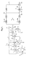
- Figure 1 schematically shows a process scheme for performing a method according the present invention.
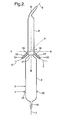
- Figure 2 schematically shows a longitudinal cross-section of a gasification reactor used in the system according to the present invention.
- Figure 3 schematically shows a longitudinal cross-section of a preferred gasification reactor, which may be used in a preferred the system according to the present invention.
- Figure 4 schematically shows a gasification reactor system for performing the two-step cooling method making use of a downstream separate vessel.
- Figure 5 schematically shows a preferred embodiment for the gasification reactor system of Figure 4.
- Figure 1 schematically shows a system 1 for producing synthesis gas.
- a gasification reactor 2 a carbonaceous stream and an oxygen containing stream may be fed via lines 3, 4, respectively.
- the solid carbonaceous feed is at least partially oxidised in the gasification reactor 2, thereby obtaining a synthesis gas and a slag.
- a synthesis gas and a slag To this end usually several burners (not shown) are present in the gasification reactor 2.
- the produced hot synthesis gas is fed via line 5 to a cooling section 6; herein the hot synthesis gas is cooled by contacting with liquid water 17.
- liquid water is injected via line 17 as will be further discussed in Figure 2 below.
- the slag drops down and is drained through line 7 for optional further processing.
- the cooled synthesis gas leaving the cooling section 6 is further processed. To this end, it is fed via line 8 into a dry solids removal unit 9 to at least partially remove dry ash in the cooled synthesis gas. Dry ash is removed form the dry solids removal unit via line 18. In an overquench mode of operation said dry-solids removal unit 9 is omitted and the cooled synthesis gas is directly fed to a wet gas scrubber 11 via line 8a and 10.
- the synthesis gas is fed via line 10 to a wet gas scrubber 11.
- Part of the scrubbed gas is subsequently fed via line 12 to a shift converter 13 to react at least a part of the water with CO to produce CO 2 and H 2 , thereby obtaining a first CO-depleted stream in line 14.
- Another part, the second sub-stream, of the scrubbed gas by-passes the shift converter 13 via line 20a.
- Waste water from gas scrubber 11 is removed via line 22 and optionally partly recycled to the gas scrubber 11 via line 23.
- vol.% water of the stream leaving the cooling section 6 in line 8 is already such that the capacity of the wet gas scrubber 11 may be substantially lowered, resulting in a significant reduction of capital expenses.
- the stream in line 16 may be fed to an indirect heat exchanger 19, for indirect heat exchange with the stream in line 17.
- the stream in line 14 is first fed to the heat exchanger 15 before entering the indirect heat exchanger 19 via line 16.
- the heat exchanger 15 may be dispensed with, if desired, or that the stream in line 14 is first fed to the indirect heat exchanger 19 before heat exchanging in heat exchanger 15.
- the heated stream in line 17 may also be partly used as a feed (line 21) to the gas scrubber 11.
- the first CO depleted stream in line 20 is fed to a combined carbon dioxide/hydrogen sulphide removal system 100 and one or more guard beds 101.
- CO 2 is discharged via line 103.
- the second substream in line 20a is fed to a combined carbon dioxide/hydrogen sulphide removal system 104 and one or more guard beds 105.
- CO 2 is discharged via line 103a.
- Part or all of the first purified CO depleted stream in line 102 is combined with the purified second substream in line 106 to obtain a second CO depleted stream in line 107.
- Another part of the purified first CO depleted stream 102 is fed to a Pressure Swing Adsorption (PSA) unit 109 to obtain purified hydrogen in line 110.
- PSA Pressure Swing Adsorption
- the combined second CO depleted stream, the purified synthesis gas, is fed via line 107 to a Fischer-Tropsch reactor 108.
- a paraffinic hydrocarbon product is obtained and discharged via line 112.
- a water by-product is discharged via line 114.
- This water-by product may be advantageously used in step (c) and supplied to the system via line 17.
- the paraffinic hydrocarbon product may be further processed in a hydroprocessing reactor 111, for example a hydroisomerisation/hydrocracking reactor, making use of the hydrogen in line 110.
- the hydroprocessing reactor, catalyst and conditions are well known to the skilled person and for example described in EP-A-537815 and EP-A-532117 .
- the reaction products, kerosene and gas oil, being among the main products, are discharged via line 113.
- Figure 2 shows a longitudinal cross-section of a gasification reactor 2 used in the system 1 of Figure 1.
- the gasification reactor 2 has an inlet 3 for a solid carbonaceous stream and an inlet 4 for an oxygen containing gas.
- burners (schematically denoted by 26) are present in the gasification reactor 2 for performing the partial oxidation reaction.
- the pair of burners is directed horizontal and diametric as shown. For reasons of simplicity, only one pair of burners 26 is shown here.
- the gasification reactor 2 comprises an outlet 25 for removing the slag formed during the partial oxidation reaction via line 7.
- the gasification reactor 2 comprises an outlet 27 for the raw synthesis gas produced, which outlet 27 is connected with the cooling section 6.
- the cooling section 6 comprises a first injector 28 (connected to line 17) that is adapted for injecting a water containing stream in the form of a mist in the cooling section.
- the first injector in use injects the mist in a direction away from the outlet 27 of the gasification reactor 2.
- the centre line X of the mist injected by the first injector 28 forms an angle ⁇ of between 30-60°, preferably about 45°, with respect to the plane A-A perpendicular to the longitudinal axis B-B of the cooling section 6.
- the cooling section also comprises a second injector 29 (connected via line 30 to a source of shielding gas) adapted for injecting a shielding fluid at least partially surrounding the mist injected by the at least one first injector 28.
- a second injector 29 connected via line 30 to a source of shielding gas
- the first injector 28 is to this end partly surrounded by second injector 29.
- the partly cooled synthesis gas leaving the cooling section 6 via line 8 may be further cooled. Examples of such further cooling are provided in figures 3 and 4.
- FIG. 3 illustrates a preferred gasification reactor comprising the following elements:
- injecting means (39) are present for injecting a liquid or gaseous cooling medium to perform the first cooling.
- the direction of said injection is as described for Figure 2 in case of liquid injections.
- injecting means (40) are present to inject liquid water, preferably in the form of a mist, preferably in a downwardly direction, into the partly cooled synthesis gas as it flows through said annular space (37) to perform the second cooling.
- Figure 3 further shows an outlet (41) for synthesis gas is present in the wall of the pressure shell (31) fluidly connected to the lower end of said annular space (37).
- the quench zone is provided with cleaning means (42) and/or (43), which are preferably mechanical rappers, which by means of vibration avoids and/or removes solids accumulating on the surfaces of the tubular part and/or of the annular space respectively.
- Figure 4 illustrates an embodiment for performing the two-step cooling method making use of a separate vessel.
- Figure 4 shows the gasification reactor (43) of Figure 1 of WO-A-2004/005438 in combination with a downstream quench vessel (44) fluidly connected by transfer duct (45).
- the system of Figure 4 differs from the system disclosed in Figure 1 of WO-A-2004/005438 in that the syngas cooler (3) of said Figure 1 of said patent publication is omitted and replaced by a simple vessel comprising means (46) to add liquid water to perform the second cooling.
- Shown in Figure 4 is the gasifier wall (47), which is connected to a tubular part (51), which in turn is connected to an upper wall part (52) as present in quench vessel (44).
- injecting means (48) are present for injecting a liquid or gaseous cooling medium to perform the first cooling as illustrated in Figure 2.
- Quench vessel (44) is further provided with an outlet (49) for cooled synthesis gas.
- Figure 4 also shows a burner (50).
- the various other details of the gasification reactor (43) and the transfer duct (45) as well as the upper design of the quench vessel (44) are preferably as disclosed for the apparatus of Figure 1 of WO-A-2004/005438 .
- Figure 5 shows the upper end of gasification reactor (43) and the upper end of gasification chamber wall (47). This upper end is fluidly connected by means of connecting conduit (51) to separate cooling vessel (53). Injecting means (48) are present to inject a gaseous or liquid quenching medium in accordance with the process of the present invention.
- a dip tube (54) is present to create a downwardly directed flow path for synthesis gas.
- injecting means (46) are present to inject a mist of liquid water into the synthesis gas.
- the dip-tube is partly submerged in a water bath (55).
- the synthesis gas will flow through water bath (55) to an annular space (56) as present between dip-tube (54) and the wall of the cooling vessel (53). From said annular space (56) the water saturated synthesis gas is discharged from said cooling vessel via conduit (57).
- Figure 5 also shows a pump (58) to recirculate water (59), providing a bleed stream (60) and a supply stream (61) for fresh water.
- a hot synthesis gas is obtained by performing a partial oxidation of a coal feedstock.
- the hot synthesis gas is quenched with recycled cold synthesis gas to obtain the gas having the properties and composition of stream 5 in Figure 1.
- Table 1 further provides flow rates, properties and compositions of various streams in Figure 1. This example shows that with the present process a synthesis gas composition can be prepared having a sufficient steam content to perform a water shift reaction.
- TABLE 1 Stream Number in Figure 1 5 17 8 10 21 12+20a 22 Temperature °C 899 230 425 424 230 213 (*) 212 Pressure BAR 41 45 41 39 45 38 42 Total Mass Rate KG/SEC 103 22 141 142,2 38,3 108,9 9,9 Total Molar Comp.
Landscapes
- Chemical & Material Sciences (AREA)
- Engineering & Computer Science (AREA)
- Combustion & Propulsion (AREA)
- Organic Chemistry (AREA)
- Chemical Kinetics & Catalysis (AREA)
- Oil, Petroleum & Natural Gas (AREA)
- General Chemical & Material Sciences (AREA)
- Health & Medical Sciences (AREA)
- Inorganic Chemistry (AREA)
- Toxicology (AREA)
- Mechanical Engineering (AREA)
- General Engineering & Computer Science (AREA)
- General Health & Medical Sciences (AREA)
- Production Of Liquid Hydrocarbon Mixture For Refining Petroleum (AREA)
- Organic Low-Molecular-Weight Compounds And Preparation Thereof (AREA)
Priority Applications (1)
| Application Number | Priority Date | Filing Date | Title |
|---|---|---|---|
| EP07119578A EP1918352B1 (fr) | 2006-11-01 | 2007-10-30 | Alimentation carbonée solide pour procédé liquide |
Applications Claiming Priority (2)
| Application Number | Priority Date | Filing Date | Title |
|---|---|---|---|
| EP06123315 | 2006-11-01 | ||
| EP07119578A EP1918352B1 (fr) | 2006-11-01 | 2007-10-30 | Alimentation carbonée solide pour procédé liquide |
Publications (2)
| Publication Number | Publication Date |
|---|---|
| EP1918352A1 true EP1918352A1 (fr) | 2008-05-07 |
| EP1918352B1 EP1918352B1 (fr) | 2009-12-09 |
Family
ID=39263159
Family Applications (1)
| Application Number | Title | Priority Date | Filing Date |
|---|---|---|---|
| EP07119578A Active EP1918352B1 (fr) | 2006-11-01 | 2007-10-30 | Alimentation carbonée solide pour procédé liquide |
Country Status (1)
| Country | Link |
|---|---|
| EP (1) | EP1918352B1 (fr) |
Cited By (9)
| Publication number | Priority date | Publication date | Assignee | Title |
|---|---|---|---|---|
| CN101825276A (zh) * | 2010-04-26 | 2010-09-08 | 中国科学院广州能源研究所 | 一种节能环保型液排渣式燃煤供热系统 |
| EP2236457A1 (fr) * | 2009-03-30 | 2010-10-06 | Shell Internationale Research Maatschappij B.V. | Procédé de production de gaz de synthèse purifié |
| WO2010112502A1 (fr) * | 2009-03-30 | 2010-10-07 | Shell Internationale Research Maatschappij B.V. | Procede de production d'un flux de gaz de synthese purifie |
| WO2010112501A1 (fr) * | 2009-03-30 | 2010-10-07 | Shell Internationale Research Maatschappij B.V. | Procede de production de gaz de synthese purifie |
| WO2010121895A1 (fr) * | 2009-03-30 | 2010-10-28 | Shell Internationale Research Maatschappij B.V. | Procédé de production de gaz de synthèse purifié |
| EP2291492A1 (fr) * | 2008-06-12 | 2011-03-09 | Cortus AB | Procédé et équipement de production d'hydrogène gazeux utilisant la biomasse |
| WO2010099896A3 (fr) * | 2009-03-04 | 2011-03-31 | Uhde Gmbh | Procédé et dispositif pour l'utilisation de l'enthalpie d'un gaz de synthèse par gazéification supplémentaire et postérieure de combustibles renouvelables |
| WO2012138766A3 (fr) * | 2011-04-06 | 2013-03-21 | Ineos Bio Sa | Système de génération de puissance à partir de procédé de fermentation de gaz de synthèse |
| WO2013174480A1 (fr) * | 2012-05-24 | 2013-11-28 | Linde Aktiengesellschaft | Procédé de production de co, de h2 et de gaz de synthèse de méthanol à partir d'un gaz de synthèse, en particulier à partir d'un effluent gazeux acétylénique |
Citations (5)
| Publication number | Priority date | Publication date | Assignee | Title |
|---|---|---|---|---|
| US4946476A (en) | 1989-08-24 | 1990-08-07 | Texaco Inc. | Partial oxidation of bituminous coal |
| EP0400740A1 (fr) | 1989-05-30 | 1990-12-05 | Shell Internationale Researchmaatschappij B.V. | Réacteur de gazéification de charbon |
| EP0926441A1 (fr) | 1996-09-04 | 1999-06-30 | Ebara Corporation | Procede de gazeification de dechets utilisant un four de fusion rotatif |
| WO2004005438A1 (fr) | 2002-07-02 | 2004-01-15 | Shell Internationale Research Maatschappij B.V. | Procede de gazeification d'une charge carbonee solide et reacteur utilise dans ce procede |
| US20040101473A1 (en) * | 2002-11-25 | 2004-05-27 | Conoco Inc. | Hydrocarbon gas to liquid conversion process |
-
2007
- 2007-10-30 EP EP07119578A patent/EP1918352B1/fr active Active
Patent Citations (5)
| Publication number | Priority date | Publication date | Assignee | Title |
|---|---|---|---|---|
| EP0400740A1 (fr) | 1989-05-30 | 1990-12-05 | Shell Internationale Researchmaatschappij B.V. | Réacteur de gazéification de charbon |
| US4946476A (en) | 1989-08-24 | 1990-08-07 | Texaco Inc. | Partial oxidation of bituminous coal |
| EP0926441A1 (fr) | 1996-09-04 | 1999-06-30 | Ebara Corporation | Procede de gazeification de dechets utilisant un four de fusion rotatif |
| WO2004005438A1 (fr) | 2002-07-02 | 2004-01-15 | Shell Internationale Research Maatschappij B.V. | Procede de gazeification d'une charge carbonee solide et reacteur utilise dans ce procede |
| US20040101473A1 (en) * | 2002-11-25 | 2004-05-27 | Conoco Inc. | Hydrocarbon gas to liquid conversion process |
Cited By (22)
| Publication number | Priority date | Publication date | Assignee | Title |
|---|---|---|---|---|
| EP2291492A1 (fr) * | 2008-06-12 | 2011-03-09 | Cortus AB | Procédé et équipement de production d'hydrogène gazeux utilisant la biomasse |
| EP2291492A4 (fr) * | 2008-06-12 | 2013-02-27 | Cortus Ab | Procédé et équipement de production d'hydrogène gazeux utilisant la biomasse |
| US9234148B2 (en) | 2009-03-04 | 2016-01-12 | Thyssenkrupp Industrial Solution Ag | Process and apparatus for the utilization of the enthalpy of a syngas by additional and post-gasification of renewable fuels |
| WO2010099896A3 (fr) * | 2009-03-04 | 2011-03-31 | Uhde Gmbh | Procédé et dispositif pour l'utilisation de l'enthalpie d'un gaz de synthèse par gazéification supplémentaire et postérieure de combustibles renouvelables |
| WO2010121895A1 (fr) * | 2009-03-30 | 2010-10-28 | Shell Internationale Research Maatschappij B.V. | Procédé de production de gaz de synthèse purifié |
| AU2010241062B2 (en) * | 2009-03-30 | 2013-10-03 | Shell Internationale Research Maatschappij B.V. | Process for producing purified synthesis gas |
| WO2010112517A1 (fr) * | 2009-03-30 | 2010-10-07 | Shell Internationale Research Maatschappij B.V. | Procede de production de flux de gaz de synthese purifie |
| WO2010112501A1 (fr) * | 2009-03-30 | 2010-10-07 | Shell Internationale Research Maatschappij B.V. | Procede de production de gaz de synthese purifie |
| CN102378643A (zh) * | 2009-03-30 | 2012-03-14 | 国际壳牌研究有限公司 | 用于生产纯化的合成气的方法 |
| JP2012521956A (ja) * | 2009-03-30 | 2012-09-20 | シエル・インターナシヨナル・リサーチ・マートスハツペイ・ベー・ヴエー | 精製合成ガスを製造する方法 |
| WO2010112502A1 (fr) * | 2009-03-30 | 2010-10-07 | Shell Internationale Research Maatschappij B.V. | Procede de production d'un flux de gaz de synthese purifie |
| EP2236457A1 (fr) * | 2009-03-30 | 2010-10-06 | Shell Internationale Research Maatschappij B.V. | Procédé de production de gaz de synthèse purifié |
| AU2010230280B2 (en) * | 2009-03-30 | 2013-08-29 | Shell Internationale Research Maatschappij B.V. | Process for producing a purified synthesis gas stream |
| US8772361B2 (en) | 2009-03-30 | 2014-07-08 | Shell Oil Company | Process for producing a purified synthesis gas stream |
| AU2010230279B2 (en) * | 2009-03-30 | 2013-10-10 | Shell Internationale Research Maatschappij B.V. | Process for producing purified synthesis gas |
| CN101825276A (zh) * | 2010-04-26 | 2010-09-08 | 中国科学院广州能源研究所 | 一种节能环保型液排渣式燃煤供热系统 |
| US8894885B2 (en) | 2011-04-06 | 2014-11-25 | Ineos Bio Sa | Apparatus and methods for tar removal from syngas |
| US9051523B2 (en) | 2011-04-06 | 2015-06-09 | Ineos Bio Sa | Apparatus and process for gasification of carbonaceous materials to produce syngas |
| WO2012138766A3 (fr) * | 2011-04-06 | 2013-03-21 | Ineos Bio Sa | Système de génération de puissance à partir de procédé de fermentation de gaz de synthèse |
| WO2013174480A1 (fr) * | 2012-05-24 | 2013-11-28 | Linde Aktiengesellschaft | Procédé de production de co, de h2 et de gaz de synthèse de méthanol à partir d'un gaz de synthèse, en particulier à partir d'un effluent gazeux acétylénique |
| US9174900B2 (en) | 2012-05-24 | 2015-11-03 | Linde Aktiengesellschaft | Method for production of CO, H2 and methanol-synthesis gas from a synthesis gas, in particular from acetylene off-gas |
| RU2627398C2 (ru) * | 2012-05-24 | 2017-08-08 | Линде Акциенгезелльшафт | Способ получения со, h2 и метанола из синтез-газа, в частности из отходящего газа производства ацетилена |
Also Published As
| Publication number | Publication date |
|---|---|
| EP1918352B1 (fr) | 2009-12-09 |
Similar Documents
| Publication | Publication Date | Title |
|---|---|---|
| US7741377B2 (en) | Solid carbonaceous feed to liquid process | |
| AU2006301154B2 (en) | Improvements relating to coal to liquid processes | |
| EP1918352B1 (fr) | Alimentation carbonée solide pour procédé liquide | |
| EP1836283B1 (fr) | Ameliorations relatives a des procedes de conversion de charbon en liquide | |
| US7931731B2 (en) | Process for production of elemental iron | |
| AU2007245731B2 (en) | Gasification system and its use | |
| AU2007245732B2 (en) | Gasification reactor and its use | |
| US8083815B2 (en) | Process to prepare methanol and/or dimethylether | |
| US20100018216A1 (en) | Carbon capture compliant polygeneration | |
| CN101631740A (zh) | 用于生产纯化的合成气物流的方法 | |
| US20070294943A1 (en) | Gasification reactor and its use | |
| US8800498B2 (en) | Systems and methods for exchanging heat in a gasification system |
Legal Events
| Date | Code | Title | Description |
|---|---|---|---|
| PUAI | Public reference made under article 153(3) epc to a published international application that has entered the european phase |
Free format text: ORIGINAL CODE: 0009012 |
|
| AK | Designated contracting states |
Kind code of ref document: A1 Designated state(s): AT BE BG CH CY CZ DE DK EE ES FI FR GB GR HU IE IS IT LI LT LU LV MC MT NL PL PT RO SE SI SK TR |
|
| AX | Request for extension of the european patent |
Extension state: AL BA HR MK RS |
|
| 17P | Request for examination filed |
Effective date: 20081107 |
|
| 17Q | First examination report despatched |
Effective date: 20081204 |
|
| AKX | Designation fees paid |
Designated state(s): AT BE BG CH CY CZ DE DK EE ES FI FR GB GR HU IE IS IT LI LT LU LV MC MT NL PL PT RO SE SI SK TR |
|
| GRAP | Despatch of communication of intention to grant a patent |
Free format text: ORIGINAL CODE: EPIDOSNIGR1 |
|
| GRAS | Grant fee paid |
Free format text: ORIGINAL CODE: EPIDOSNIGR3 |
|
| GRAA | (expected) grant |
Free format text: ORIGINAL CODE: 0009210 |
|
| AK | Designated contracting states |
Kind code of ref document: B1 Designated state(s): AT BE BG CH CY CZ DE DK EE ES FI FR GB GR HU IE IS IT LI LT LU LV MC MT NL PL PT RO SE SI SK TR |
|
| REG | Reference to a national code |
Ref country code: GB Ref legal event code: FG4D |
|
| REG | Reference to a national code |
Ref country code: CH Ref legal event code: EP |
|
| REG | Reference to a national code |
Ref country code: IE Ref legal event code: FG4D |
|
| REF | Corresponds to: |
Ref document number: 602007003665 Country of ref document: DE Date of ref document: 20100121 Kind code of ref document: P |
|
| REG | Reference to a national code |
Ref country code: NL Ref legal event code: T3 |
|
| PG25 | Lapsed in a contracting state [announced via postgrant information from national office to epo] |
Ref country code: SE Free format text: LAPSE BECAUSE OF FAILURE TO SUBMIT A TRANSLATION OF THE DESCRIPTION OR TO PAY THE FEE WITHIN THE PRESCRIBED TIME-LIMIT Effective date: 20091209 Ref country code: FI Free format text: LAPSE BECAUSE OF FAILURE TO SUBMIT A TRANSLATION OF THE DESCRIPTION OR TO PAY THE FEE WITHIN THE PRESCRIBED TIME-LIMIT Effective date: 20091209 Ref country code: LT Free format text: LAPSE BECAUSE OF FAILURE TO SUBMIT A TRANSLATION OF THE DESCRIPTION OR TO PAY THE FEE WITHIN THE PRESCRIBED TIME-LIMIT Effective date: 20091209 |
|
| LTIE | Lt: invalidation of european patent or patent extension |
Effective date: 20091209 |
|
| PG25 | Lapsed in a contracting state [announced via postgrant information from national office to epo] |
Ref country code: PL Free format text: LAPSE BECAUSE OF FAILURE TO SUBMIT A TRANSLATION OF THE DESCRIPTION OR TO PAY THE FEE WITHIN THE PRESCRIBED TIME-LIMIT Effective date: 20091209 Ref country code: SI Free format text: LAPSE BECAUSE OF FAILURE TO SUBMIT A TRANSLATION OF THE DESCRIPTION OR TO PAY THE FEE WITHIN THE PRESCRIBED TIME-LIMIT Effective date: 20091209 Ref country code: LV Free format text: LAPSE BECAUSE OF FAILURE TO SUBMIT A TRANSLATION OF THE DESCRIPTION OR TO PAY THE FEE WITHIN THE PRESCRIBED TIME-LIMIT Effective date: 20091209 |
|
| PG25 | Lapsed in a contracting state [announced via postgrant information from national office to epo] |
Ref country code: AT Free format text: LAPSE BECAUSE OF FAILURE TO SUBMIT A TRANSLATION OF THE DESCRIPTION OR TO PAY THE FEE WITHIN THE PRESCRIBED TIME-LIMIT Effective date: 20091209 |
|
| PG25 | Lapsed in a contracting state [announced via postgrant information from national office to epo] |
Ref country code: EE Free format text: LAPSE BECAUSE OF FAILURE TO SUBMIT A TRANSLATION OF THE DESCRIPTION OR TO PAY THE FEE WITHIN THE PRESCRIBED TIME-LIMIT Effective date: 20091209 Ref country code: BG Free format text: LAPSE BECAUSE OF FAILURE TO SUBMIT A TRANSLATION OF THE DESCRIPTION OR TO PAY THE FEE WITHIN THE PRESCRIBED TIME-LIMIT Effective date: 20100309 Ref country code: PT Free format text: LAPSE BECAUSE OF FAILURE TO SUBMIT A TRANSLATION OF THE DESCRIPTION OR TO PAY THE FEE WITHIN THE PRESCRIBED TIME-LIMIT Effective date: 20100409 Ref country code: ES Free format text: LAPSE BECAUSE OF FAILURE TO SUBMIT A TRANSLATION OF THE DESCRIPTION OR TO PAY THE FEE WITHIN THE PRESCRIBED TIME-LIMIT Effective date: 20100320 Ref country code: RO Free format text: LAPSE BECAUSE OF FAILURE TO SUBMIT A TRANSLATION OF THE DESCRIPTION OR TO PAY THE FEE WITHIN THE PRESCRIBED TIME-LIMIT Effective date: 20091209 Ref country code: IS Free format text: LAPSE BECAUSE OF FAILURE TO SUBMIT A TRANSLATION OF THE DESCRIPTION OR TO PAY THE FEE WITHIN THE PRESCRIBED TIME-LIMIT Effective date: 20100409 |
|
| PG25 | Lapsed in a contracting state [announced via postgrant information from national office to epo] |
Ref country code: SK Free format text: LAPSE BECAUSE OF FAILURE TO SUBMIT A TRANSLATION OF THE DESCRIPTION OR TO PAY THE FEE WITHIN THE PRESCRIBED TIME-LIMIT Effective date: 20091209 Ref country code: BE Free format text: LAPSE BECAUSE OF FAILURE TO SUBMIT A TRANSLATION OF THE DESCRIPTION OR TO PAY THE FEE WITHIN THE PRESCRIBED TIME-LIMIT Effective date: 20091209 Ref country code: CZ Free format text: LAPSE BECAUSE OF FAILURE TO SUBMIT A TRANSLATION OF THE DESCRIPTION OR TO PAY THE FEE WITHIN THE PRESCRIBED TIME-LIMIT Effective date: 20091209 |
|
| PLBE | No opposition filed within time limit |
Free format text: ORIGINAL CODE: 0009261 |
|
| STAA | Information on the status of an ep patent application or granted ep patent |
Free format text: STATUS: NO OPPOSITION FILED WITHIN TIME LIMIT |
|
| PG25 | Lapsed in a contracting state [announced via postgrant information from national office to epo] |
Ref country code: GR Free format text: LAPSE BECAUSE OF FAILURE TO SUBMIT A TRANSLATION OF THE DESCRIPTION OR TO PAY THE FEE WITHIN THE PRESCRIBED TIME-LIMIT Effective date: 20100310 Ref country code: CY Free format text: LAPSE BECAUSE OF FAILURE TO SUBMIT A TRANSLATION OF THE DESCRIPTION OR TO PAY THE FEE WITHIN THE PRESCRIBED TIME-LIMIT Effective date: 20091209 |
|
| 26N | No opposition filed |
Effective date: 20100910 |
|
| PG25 | Lapsed in a contracting state [announced via postgrant information from national office to epo] |
Ref country code: DK Free format text: LAPSE BECAUSE OF FAILURE TO SUBMIT A TRANSLATION OF THE DESCRIPTION OR TO PAY THE FEE WITHIN THE PRESCRIBED TIME-LIMIT Effective date: 20091209 |
|
| PG25 | Lapsed in a contracting state [announced via postgrant information from national office to epo] |
Ref country code: IT Free format text: LAPSE BECAUSE OF FAILURE TO SUBMIT A TRANSLATION OF THE DESCRIPTION OR TO PAY THE FEE WITHIN THE PRESCRIBED TIME-LIMIT Effective date: 20091209 |
|
| PG25 | Lapsed in a contracting state [announced via postgrant information from national office to epo] |
Ref country code: MC Free format text: LAPSE BECAUSE OF NON-PAYMENT OF DUE FEES Effective date: 20101031 |
|
| PG25 | Lapsed in a contracting state [announced via postgrant information from national office to epo] |
Ref country code: IE Free format text: LAPSE BECAUSE OF NON-PAYMENT OF DUE FEES Effective date: 20101030 |
|
| PG25 | Lapsed in a contracting state [announced via postgrant information from national office to epo] |
Ref country code: MT Free format text: LAPSE BECAUSE OF FAILURE TO SUBMIT A TRANSLATION OF THE DESCRIPTION OR TO PAY THE FEE WITHIN THE PRESCRIBED TIME-LIMIT Effective date: 20091209 |
|
| REG | Reference to a national code |
Ref country code: CH Ref legal event code: PL |
|
| PG25 | Lapsed in a contracting state [announced via postgrant information from national office to epo] |
Ref country code: LI Free format text: LAPSE BECAUSE OF NON-PAYMENT OF DUE FEES Effective date: 20111031 Ref country code: CH Free format text: LAPSE BECAUSE OF NON-PAYMENT OF DUE FEES Effective date: 20111031 |
|
| PG25 | Lapsed in a contracting state [announced via postgrant information from national office to epo] |
Ref country code: HU Free format text: LAPSE BECAUSE OF FAILURE TO SUBMIT A TRANSLATION OF THE DESCRIPTION OR TO PAY THE FEE WITHIN THE PRESCRIBED TIME-LIMIT Effective date: 20100610 Ref country code: LU Free format text: LAPSE BECAUSE OF NON-PAYMENT OF DUE FEES Effective date: 20101030 |
|
| PG25 | Lapsed in a contracting state [announced via postgrant information from national office to epo] |
Ref country code: TR Free format text: LAPSE BECAUSE OF FAILURE TO SUBMIT A TRANSLATION OF THE DESCRIPTION OR TO PAY THE FEE WITHIN THE PRESCRIBED TIME-LIMIT Effective date: 20091209 |
|
| PGFP | Annual fee paid to national office [announced via postgrant information from national office to epo] |
Ref country code: FR Payment date: 20141008 Year of fee payment: 8 |
|
| PGFP | Annual fee paid to national office [announced via postgrant information from national office to epo] |
Ref country code: NL Payment date: 20141010 Year of fee payment: 8 |
|
| REG | Reference to a national code |
Ref country code: NL Ref legal event code: MM Effective date: 20151101 |
|
| REG | Reference to a national code |
Ref country code: FR Ref legal event code: ST Effective date: 20160630 |
|
| PG25 | Lapsed in a contracting state [announced via postgrant information from national office to epo] |
Ref country code: FR Free format text: LAPSE BECAUSE OF NON-PAYMENT OF DUE FEES Effective date: 20151102 Ref country code: NL Free format text: LAPSE BECAUSE OF NON-PAYMENT OF DUE FEES Effective date: 20151101 |
|
| REG | Reference to a national code |
Ref country code: GB Ref legal event code: 732E Free format text: REGISTERED BETWEEN 20181025 AND 20181102 |
|
| REG | Reference to a national code |
Ref country code: DE Ref legal event code: R081 Ref document number: 602007003665 Country of ref document: DE Owner name: AIR PRODUCTS AND CHEMICALS, INC,, ALLENTOWN, US Free format text: FORMER OWNER: SHELL INTERNATIONALE RESEARCH MAATSCHAPPIJ B.V., DEN HAAG/S'GRAVENHAGE, NL |
|
| P01 | Opt-out of the competence of the unified patent court (upc) registered |
Effective date: 20230517 |
|
| PGFP | Annual fee paid to national office [announced via postgrant information from national office to epo] |
Ref country code: GB Payment date: 20230907 Year of fee payment: 17 |
|
| PGFP | Annual fee paid to national office [announced via postgrant information from national office to epo] |
Ref country code: DE Payment date: 20230906 Year of fee payment: 17 |