EP1918239A1 - Elevator device - Google Patents
Elevator device Download PDFInfo
- Publication number
- EP1918239A1 EP1918239A1 EP05780959A EP05780959A EP1918239A1 EP 1918239 A1 EP1918239 A1 EP 1918239A1 EP 05780959 A EP05780959 A EP 05780959A EP 05780959 A EP05780959 A EP 05780959A EP 1918239 A1 EP1918239 A1 EP 1918239A1
- Authority
- EP
- European Patent Office
- Prior art keywords
- brake
- car
- group
- driving
- braking
- Prior art date
- Legal status (The legal status is an assumption and is not a legal conclusion. Google has not performed a legal analysis and makes no representation as to the accuracy of the status listed.)
- Granted
Links
Images




Classifications
-
- B—PERFORMING OPERATIONS; TRANSPORTING
- B66—HOISTING; LIFTING; HAULING
- B66B—ELEVATORS; ESCALATORS OR MOVING WALKWAYS
- B66B1/00—Control systems of elevators in general
- B66B1/24—Control systems with regulation, i.e. with retroactive action, for influencing travelling speed, acceleration, or deceleration
- B66B1/28—Control systems with regulation, i.e. with retroactive action, for influencing travelling speed, acceleration, or deceleration electrical
- B66B1/32—Control systems with regulation, i.e. with retroactive action, for influencing travelling speed, acceleration, or deceleration electrical effective on braking devices, e.g. acting on electrically controlled brakes
-
- B—PERFORMING OPERATIONS; TRANSPORTING
- B66—HOISTING; LIFTING; HAULING
- B66B—ELEVATORS; ESCALATORS OR MOVING WALKWAYS
- B66B7/00—Other common features of elevators
- B66B7/06—Arrangements of ropes or cables
- B66B7/10—Arrangements of ropes or cables for equalising rope or cable tension
-
- B—PERFORMING OPERATIONS; TRANSPORTING
- B66—HOISTING; LIFTING; HAULING
- B66B—ELEVATORS; ESCALATORS OR MOVING WALKWAYS
- B66B9/00—Kinds or types of lifts in, or associated with, buildings or other structures
Definitions
- the present invention relates to an elevator apparatus for raising and lowering a car by driving forces of a plurality of driving machines.
- a car is raised and lowered by a first driving machine and a second driving machine which are provided in an upper portion of a hoistway.
- the car is provided with a sensor for detecting an inclination of the car.
- the first and second driving machines are controlled so as to cancel the inclination of the car according to signals from the sensor (see, for example, Patent Document 1) .
- Patent Document 1 WO 2004/026749 A1
- the present invention has been made with a view toward solving the above-mentionedproblem. It is an object of the present invention to provide an elevator apparatus capable of restraining generation of an inclination of the car at the time of emergency braking.
- An elevator apparatus includes: a plurality of driving machines; a car that is raised and lowered by driving forces of the driving machines; and a plurality of brake devices for braking the ascent and descent of the car, in which the brake devices have a plurality of brake main bodies belonging to a plurality of different groups, and in which, at the time of emergency braking, the brake devices generate braking forces by the brake main bodies with timings deviated from group to group.
- Fig. 1 is a schematic view of an elevator apparatus according to Embodiment 1 of the present invention.
- first and second driving machines i.e., hoists
- the first driving machine 1 has a first driving sheave 3, a first motor 4 for rotating the first driving sheave 3, a first brake drum 5, which is a brake rotary member to be rotated integrally with the first driving sheave 3, and a first brake device 6 for braking the rotation of the first brake drum 5.
- the second driving machine 2 has a second driving sheave 7, a second motor 8 for rotating the second driving sheave 7, a second brake drum 9, which is a brake rotary member to be rotated integrally with the second driving sheave 7, and a second brake device 10 for braking the rotation of the second brake drum 9.
- a plurality of first main ropes 11 (only one of which is shown in the drawing) are wound around the first driving sheave 3.
- a plurality of second main ropes 12 (only one of which is shown in the drawing) are wound around the second driving sheave 7.
- a car 13 is connected to first end portions of the first and second main ropes 11 and 12.
- a first counterweight 14 is connected to second end portions of the first main ropes 11.
- a second counterweight 15 is connected to second end portions of the second main ropes 12. That is, the car 13 and the first and second counterweights 14 and 15 are suspended in the hoistway by the first and second main ropes 11 and 12 through a 1:1 roping system, and are raised and lowered in the hoistway by the driving forces of the first and second driving devices 1 and 2.
- first rope connecting portion 13a and a second rope connecting portion 13b are provided on the opposite side of the first rope connecting portion 13a with respect to the center of gravity of the car 13.
- first and second rope connecting portions 13a and 13b are arranged symmetrically with respect to the center of gravity of the car 13.
- the first main ropes 11 are connected to the first rope connecting portion 13a
- the second main ropes 12 are connected to the second rope connecting portion 13b.
- the first brake device 6 has first through third brake main bodies 16a through 16c belonging to a plurality of different groups (here, first through third groups) .
- the second brake device 10 has fourth through sixth brake main bodies 16d through 16f belonging toapluralityofdifferentgroups (here, first through third groups) .
- first and fourth brake main bodies 16a and 16d belong to the first group
- the second and fifth brake main bodies 16b and 16e belong to the second group
- the third and sixth brake main bodies 16c and 16f belong to the third group.
- the first brake main body 16a has a first brake shoe 17a to be brought into and out of contact with the braking surface of the first brake drum 5, a first brake spring (i.e., mechanical spring) 18a for pressing the first brake shoe 17a against the first brake drum 5, a first iron core 19a fixed to the first brake shoe 17a, and a first electromagnetic coil 20a for attracting the first iron core 19a to thereby separate the first brake shoe 17a from the first brake drum 5.
- a first brake spring i.e., mechanical spring
- the second through sixth brake main bodies 16b through 16f have brake shoes 17b through 17f, brake springs 18b through 18f, iron cores 19b through 19f, and electromagnetic coils 20b through 20f, respectively.
- Fig. 2 is a circuit diagram showing driving circuits for the first through sixth electromagnetic coils 20a through 20f. Electric currents from first through sixth brake attraction amplifiers 21a through 21f are supplied to the electromagnetic coils 20a through 20f through an electromagnetic switch device 22, respectively.
- the electromagnetic switch device 22 has first through sixth contacts 22a through 22f connected between the brake attraction amplifiers 21a through 21f and the electromagnetic coils 20a through 20f, respectively, and an opening/closing drive portion 22g for opening and closing the contacts 22a through 22f.
- the opening/closing drive portion 22g has an iron core 22h, a switch coil 22i wound around the iron core 22h, and a resistor 22j and a diode 22k connected in parallel to the switch coil 22i.
- the contacts 22a through 22f are normally closed. However, when an emergency stop command signal is input to the opening/closing drive portion 22g, the contacts 22a through 22f are opened. This causes the electric currents supplied to the electromagnetic coils 20a through 20f of the brake main bodies 16a through 16f to be cut off simultaneously.
- First through sixth corresponding resistors 23a through 23f and first through sixth corresponding diodes 24a through 24f are connected in parallel to the first through sixth electromagnetic coils 20a through 20f.
- the diodes 24a through 24f are connected in series to the corresponding resistors 23a through 23f.
- the electric resistance values of the resistors 23a through 23f connected to the electromagnetic coils 20a through 20f belonging to the same group are set to be the same.
- the electric resistance values of the resistors 23a through 23f connected to the electromagnetic coils 20a through 20f belonging to different groups are set to be different.
- the electric resistance value R1 of the first resistor 23a is larger than the electric resistance value R2 of the second resistor 23b (i.e., R1 > R2)
- the electric resistance value R2 of the second resistor 23b is larger than the electric resistance value R3 of the third resistor 23c (i.e., R2 > R3).
- the operation of this embodiment will be described.
- the first and second motors 4 and 8 are driven in synchronism with each other, whereby the first and the second sheaves 3 and 7 are rotated simultaneously, and the car 13 and the counterweights 14 and 15 are raised and lowered in the hoistway.
- the brake shoes 17a through 17f are kept away from the brake drums 5 and 9 by the electromagnetic actuators composed of the iron cores 19a through 19f and the electromagnetic coils 20a through 20f against the forces of the brake springs 18a through 18f.
- the electromagnetic coils 20a through 20f are in a non-energized state, and the brake shoes 17a through 17f are pressed against the brake drums 5 and 9 by the spring forces of the brake springs 18a through 18f, thus keeping the car 13 at rest.
- the electric resistance values of the resistors 23a through 23f connected in parallel to the electromagnetic coils 20a through 20f are set as described above, so the timings with which the braking forces are generated by the brake main bodies 16a through 16f are slightly deviated from group to group. That is, the brake main bodies 16a through 16f are grouped in terms of brake operation timing.
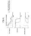
- Fig. 3 is an explanatory view showing a difference in operation between the brake main bodies 16a through 16f due to a difference in electric resistance value between the resistors 23a through 23f of Fig. 2 .
- the period of time between the moment when the power supply to the electromagnetic coils 20a through 20f is cut off by the emergency stop command and the moment when the electric current flowing through the electromagnetic coils 20a through 20f is reduced to 0 is shortened when the electric resistance values of the resistors 23a through 23f are increased.
- the larger the electric resistance values of the resistors 23a through 23f the quicker the shoe gaps (i.e., the gaps between the brake shoes 17a through 17f and the brake drums 5 and 9) are reduced to 0. That is, the larger the electric resistance values of the resistors 23a through 23f, the earlier the braking forces are generated and exerted.
- the braking forces are generated in the order: the first and fourth brake main bodies 16a and 16d, the second and fifth brake main bodies 16b and 16e, and the third and sixth brake main bodies 16c and 16f.
- the timings with which the braking forces are generated by the brake main bodies 16a through 16f are deviated from group to group, so it is possible to prevent an excessive deceleration frombeing applied to the car 13. Further, since the braking forces are applied to the first and second brake drums 5 and 9 a plurality of times, so if there should be a slight deviation in braking timing between the right and left sides, the difference in braking force is small. Thus, it is possible to prevent generation of an inclination of the car 13 at the time of emergency braking.
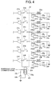
- Fig. 4 is a circuit diagram showing driving circuits for the first through sixth electromagnetic coils 20a through 20f of an elevator apparatus according to Embodiment 2 of the present invention.
- the overall construction of the elevator apparatus is the same as that of Embodiment 1 (shown in Fig. 1 ).
- two first resistors 23a1 and 23a2 are provided in a circuit in parallel with the first electromagnetic coil 20a.
- the first resistors 23a1 and 23a2 are connected in parallel to each other, and are connected in series to the first diode 24a.
- first selection switch 25a selectively connecting one of the first resistors 23a1 and 23a2 to the first diode 24a.
- second through sixth electromagnetic coils 20b through 20f there are connected second through sixth resistors 23b1 through 23f2 and second through sixth selection switches 25b through 25f, respectively.
- the electric resistance value of the first resistor 23a1 is set to be slightly larger than the electric resistance value of the first resistor 23a2 .
- the electric resistance value of the second resistor 23b1 is set to be slightly larger than the electric resistance value of the second resistor 23b2.
- the electric resistance value of the third resistor 23c1 is set to be slightly larger than the electric resistance value of the third resistor 23c2.
- the electric resistance value of the fourth resistor 23d1 is set to be slightly larger than the electric resistance value of the fourth resistor 23d2.
- the electric resistance value of the fifth resistor 23e1 is set to be slightly larger than the electric resistance value of the fifth resistor 23e2.
- the electric resistance value of the sixth resistor 23f 1 is set to be slightly larger than the electric resistance value of the sixth resistor 23f2.
- the electric resistance value of the first resistor 23a1 is equal to the electric resistance value of the fourth resistor 23d1.
- the electric resistance value of the first resistor 23a2 is equal to the electric resistance value of the fourth resistor 23d2.
- the electric resistance value of the second resistor 23b1 is equal to the electric resistance value of the fifth resistor 23e1.
- the electric resistance value of the second resistor 23b2 is equal to the electric resistance value of the fifth resistor 23e2.
- the electric resistance value of the third resistor 23c1 is equal to the electric resistance value of the sixth resistor 23f1.
- the electric resistance value of the third resistor 23c2 is equal to the electric resistance value of the sixth resistor 23f2.
- the electric resistance values of the first resistors 23a1 and 23a2 are larger than the electric resistance values of the second resistors 23b1 and 23b2.
- the electric resistance values of the second resistors 23b1 and 23b2 are larger than the electric resistance values of the third resistors 23c1 and 23c2.
- Fig. 5 is a block diagram showing a control portion for controlling the first through sixth selection switches 25a through 25f of Fig. 4 .
- First and second weighing devices 26 and 27 output signals corresponding to the load of the car 13.
- the first weighing device 26 is provided at the first rope connecting portion 13a.
- the second weighing device 27 is provided at the second rope connecting portion 13b.
- the weighing devices 26 and 27 output signals corresponding to the respective tensions of the main ropes 11 and 12, through expansion and contraction of built-in elastic bodies.
- the signals from the weighing devices 26 and 27 are input to a comparing portion 28.
- the comparing portion 28 compares the signals from the weighing devices 26 and 27 with each other, thereby detecting an imbalance between the tension of the first main ropes 11 and the tension of the secondmain ropes 12.
- a command generating portion 29 generates a command signal for operating the selection switches 25a through 25f according to the imbalance detection result obtained by the comparing portion 28.
- the command generating portion 29 performs switching operation on the selection switches 25a through 25f so as to deviate the braking force generating timings of the brake main bodies 16a through 16f belonging to the same group from each other according to the difference in tension between the first and second main ropes 11 and 12. For example, when the tension of the first main ropes 11 is higher than the tension of the second main ropes 12, the first through third resistors 23a1, 23b1, and 23c1 and the fourth through sixth resistors 23d2, 23e2, and 23f are selected.
- the fourth brake main body 16d generates a braking force slightly earlier than the first brake main body 16a.
- the fifth brake main body 16e generates a braking force slightly earlier than the second brake main body 16b.
- the sixth brake main body 16f generates a braking force slightly earlier than the third brake main body 16c.
- the comparing portion 28 and the command generating portion 29 may be formed by computers performing operations on the signals from the weighing devices 26 and 27 converted to digital signals, or by analog circuits using analog signals from the weighing devices 26 and 27 as they are.
- the braking force generating timings of the brake main bodies 16a through 16f belonging to the same group are deviated from each other to cancel the difference in tension between the first and second main ropes 11 and 12, so it is possible to more effectively restrain generation of an inclination of the car 13 at the time of emergency braking.
- Fig. 6 is a block diagram showing a control portion for controlling the first through sixth selection switches 25a through 25f of an elevator apparatus according to Embodiment 3 of the present invention.
- a command generating portion 31 instead of the weighing devices 26 and 27, a command generating portion 31 generates a command for performing switching on the selection switches 25a through 25f according to a signal from a car inclination sensor 30 adapted to output a signal corresponding to an inclination of the car 13.
- the command generating portion 31 outputs a command signal to the selection switches 25a through 25f so as to deviate the braking force generating timings of the brake main bodies 16a through 16f belonging to the same group to thereby cancel the inclination of the car 13.
- this embodiment has the same construction as Embodiment 2.
- the braking force generating timings of the brake main bodies 16a through 16f belonging to the same group are deviated from each other so as to cancel the inclination of the car 13, so it is possible to more effectively restrain generation of an inclination of the car 13 at the time of emergency braking.
- Fig. 7 is a circuit diagram showing driving circuits for the first through sixth electromagnetic coils 20a through 20f of an elevator apparatus according to Embodiment 4 of the present invention.
- the construction of the elevator apparatus as a whole is the same as that of Embodiment 1 (shown in Fig. 1 ).
- Electric currents from the first and fourth brake attraction amplifiers 21a and 21d are supplied to the first and fourth electromagnetic coils 20a and 20d, respectively, which belong to the first group, through a first electromagnetic switch device 32.
- the first electromagnetic switch device 32 has the contacts 22a and 22d connected between the brake attraction amplifiers 21a and 21d and the electromagnetic coils 20a and 20d, and a first opening/closing drive portion 32a for opening and closing the contacts 22a and 22d.
- the first opening/closing drive portion 32a has a first iron core 32b, a first switch coil 32c wound around the first iron core 32b, and a first resistor 32d and a first diode 32e, which are connected in parallel to the first switch coil 32c.
- Electric currents from the second and fifth brake attraction amplifiers 21b and 21e are supplied to the second and fifth electromagnetic coils 20b and 20e, respectively, which belong to the second group, through a second electromagnetic switch device 33.
- the second electromagnetic switch device 33 has the contacts 22b and 22e, and a second opening/closing drive portion 33a.
- the second opening/closing drive portion 33a has a second iron core 33b, a second switch coil 33c, a second resistor 33d, and a second diode 33e.
- Electric currents from the third and sixth brake attraction amplifiers 21c and 21f are supplied to the third and sixth electromagnetic coils 20c and 20f, respectively, which belong to the third group, through a third electromagnetic switch device 34.
- the third electromagnetic switch device 34 has the contacts 22c and 22f, and a third opening/closing drive portion 34a.
- the third opening/closing drive portion 34a has a third iron core 34b, a third switch coil 34c, a third resistor 34d, and a third diode 34e.
- the contacts 22a through 22f are normally closed. However, when an emergency stop command signal is input to the opening/closing drive portions 32 through 34, the contacts 22a through 22f are opened, whereby the electric currents supplied to the electromagnetic coils 20a through 20f of the brake main bodies 16a through 16f are cut off.
- the respective electric resistance values of the resistors 32d, 33d, and 34d, which belong to different groups, are different from one another.
- the electric resistance value of the first resistor 32d is larger than the electric resistance value of the second resistor 33d
- the electric resistance value of the second resistor 33d is larger than the electric resistance value of the third resistor 34d.
- Fig. 8 is an explanatory view showing a difference in contact opening operation between the electromagnetic switch devices 32 through 34 due to the difference in electric resistance value between the resistors 32d, 33d, and 34d of Fig. 7 .
- the period of time between the moment when an emergency stop command signal is input to the opening/closing drive portions 32a, 33a, and 34a (i.e., when the voltage of the command signal is reduced to 0) and the moment when the contacts 22a through 22f are actually opened is shortened when the electric resistance values of the resistors 32d, 33d, and 34d are increased.
- the braking forces are generated in the order: the first and fourth brake main bodies 16a and 16d, the second and fifth brake main bodies 16b and 16e, and the third and sixth brake main bodies 16c and 16f.
- the timings with which the braking forces are generated by the brake main bodies 16a through 16f are deviated from group to group, so it is possible to prevent an excessive deceleration frombeing applied to the car 13. Further, since the braking forces are applied to the first and second brake drums 5 and 9 a plurality of times, it is possible to restrain generation of an inclination of the car 13 at the time of emergency braking.
- one brake device is provided with three brake main bodies in the examples described above, it is also possible for one brake device to be provided with two or four or more brake main bodies. Further, while all the brake main bodies provided in one brake device belong to different groups from one another in the examples described above, it is also possible for a plurality of brake main bodies to belong to the same group. For example, when providing four brake main bodies in one brake device, it is possible for the four brake main bodies to be divided into two groups each including two brake main bodies.
- the number of driving machines may be three or more.
- the number of counterweights may be one or three or more.
- the timings with which the braking operations are started are deviated from group to group of the brake main bodies 16a through 16f in the examples described above, it is also possible to divide the brake main bodies into a plurality of groups, with intermittent or continuous control methods for the braking forces differing from group to group.
- the present invention is applied to a brake device for braking the rotation of a driving sheave in the examples described above, the present invention is also applicable to a brake device for braking the ascent/descent of a car by some other method.
- the present invention may also be applied to a plurality of car brake devices mounted to the car, for braking the ascent and descent of a car by holding braking members in press contact with car guide rails.
- each car brake device is provided with a plurality of brake main bodies belonging to a plurality of different groups.
- the present invention may also be applied to a plurality of rope brake devices provided in a hoistway or on a support member supporting a driving machine and adapted to brake the ascent and descent of a car through braking of the movement of main ropes.
- each rope brake device is provided with a plurality of brake main bodies belonging to a plurality of different groups.
Landscapes
- Engineering & Computer Science (AREA)
- Automation & Control Theory (AREA)
- Structural Engineering (AREA)
- Cage And Drive Apparatuses For Elevators (AREA)
- Elevator Control (AREA)
- Lift-Guide Devices, And Elevator Ropes And Cables (AREA)
- Braking Arrangements (AREA)
Abstract
Description
- The present invention relates to an elevator apparatus for raising and lowering a car by driving forces of a plurality of driving machines.
- In a conventional elevator apparatus, a car is raised and lowered by a first driving machine and a second driving machine which are provided in an upper portion of a hoistway. The car is provided with a sensor for detecting an inclination of the car. During traveling of the car, the first and second driving machines are controlled so as to cancel the inclination of the car according to signals from the sensor (see, for example, Patent Document 1) .
- Patent Document 1:
WO 2004/026749 A1 - In the conventional elevator apparatus as described above, when braking timings of brake devices of a first driving machine and a second driving machine are deviated from each other at the time of emergency braking, an inclination of the car is generated, so there is a fear of the passenger in the car experiencing discomfort.
- The present invention has been made with a view toward solving the above-mentionedproblem. It is an object of the present invention to provide an elevator apparatus capable of restraining generation of an inclination of the car at the time of emergency braking.
- An elevator apparatus according to the present invention includes: a plurality of driving machines; a car that is raised and lowered by driving forces of the driving machines; and a plurality of brake devices for braking the ascent and descent of the car, in which the brake devices have a plurality of brake main bodies belonging to a plurality of different groups, and in which, at the time of emergency braking, the brake devices generate braking forces by the brake main bodies with timings deviated from group to group.
-
- [
Fig. 1] Fig. 1 is a schematic view of an elevator apparatus according toEmbodiment 1 of the present invention. - [
Fig. 2] Fig. 2 is a circuit diagram showing driving circuits for first through sixth electromagnetic coils ofFig. 1 . - [
Fig. 3] Fig. 3 is an explanatory view illustrating a difference in operation between brake main bodies due to a difference in electric resistance value between resistors ofFig. 2 . - [
Fig. 4] Fig. 4 is a circuit diagram showing driving circuits for first through sixth electromagnetic coils of an elevator apparatus according toEmbodiment 2 of the present invention. - [
Fig. 5] Fig. 5 is a block diagram showing a control portion for controlling first through sixth selection switches ofFig. 4 . - [
Fig. 6] Fig. 6 is a block diagram showing a control portion for controlling first through sixth selection switches of an elevator apparatus according toEmbodiment 3 of the present invention. - [
Fig. 7] Fig. 7 is a circuit diagram showing driving circuits for first through sixth electromagnetic coils of an elevator apparatus according toEmbodiment 4 of the present invention. - [
Fig. 8] Fig. 8 is an explanatory view showing a difference in contact opening operation between electromagnetic switch devices due to a difference in electric resistance value between resistors ofFig. 7 . - In the following, preferred embodiments of the present invention will be described with reference to the drawings.
-
Fig. 1 is a schematic view of an elevator apparatus according toEmbodiment 1 of the present invention. In the drawing, first and second driving machines (i.e., hoists) 1 and 2 are installed in an upper portion of a hoistway. Thefirst driving machine 1 has afirst driving sheave 3, afirst motor 4 for rotating thefirst driving sheave 3, afirst brake drum 5, which is a brake rotary member to be rotated integrally with thefirst driving sheave 3, and afirst brake device 6 for braking the rotation of thefirst brake drum 5. - The
second driving machine 2 has asecond driving sheave 7, asecond motor 8 for rotating the second drivingsheave 7, asecond brake drum 9, which is a brake rotary member to be rotated integrally with the second drivingsheave 7, and asecond brake device 10 for braking the rotation of thesecond brake drum 9. - A plurality of first main ropes 11 (only one of which is shown in the drawing) are wound around the
first driving sheave 3. A plurality of second main ropes 12 (only one of which is shown in the drawing) are wound around the second drivingsheave 7. - A
car 13 is connected to first end portions of the first and secondmain ropes first counterweight 14 is connected to second end portions of the firstmain ropes 11. Asecond counterweight 15 is connected to second end portions of the secondmain ropes 12. That is, thecar 13 and the first andsecond counterweights main ropes second driving devices - Provided on the
car 13 are a firstrope connecting portion 13a and a secondrope connecting portion 13b arranged on the opposite side of the firstrope connecting portion 13a with respect to the center of gravity of thecar 13. In a vertical projection plane, the first and secondrope connecting portions car 13. The firstmain ropes 11 are connected to the firstrope connecting portion 13a, and the secondmain ropes 12 are connected to the secondrope connecting portion 13b. - The
first brake device 6 has first through third brakemain bodies 16a through 16c belonging to a plurality of different groups (here, first through third groups) . Thesecond brake device 10 has fourth through sixth brakemain bodies 16d through 16f belonging toapluralityofdifferentgroups (here, first through third groups) . - To be more specific, the first and fourth brake
main bodies main bodies main bodies - The first brake
main body 16a has a first brake shoe 17a to be brought into and out of contact with the braking surface of thefirst brake drum 5, a first brake spring (i.e., mechanical spring) 18a for pressing the first brake shoe 17a against thefirst brake drum 5, afirst iron core 19a fixed to the first brake shoe 17a, and a firstelectromagnetic coil 20a for attracting thefirst iron core 19a to thereby separate the first brake shoe 17a from thefirst brake drum 5. - Like the first brake
main body 16a, the second through sixth brakemain bodies 16b through 16f have brake shoes 17b through 17f,brake springs 18b through 18f,iron cores 19b through 19f, andelectromagnetic coils 20b through 20f, respectively. -
Fig. 2 is a circuit diagram showing driving circuits for the first through sixthelectromagnetic coils 20a through 20f. Electric currents from first through sixth brake attraction amplifiers 21a through 21f are supplied to theelectromagnetic coils 20a through 20f through anelectromagnetic switch device 22, respectively. - The
electromagnetic switch device 22 has first throughsixth contacts 22a through 22f connected between thebrake attraction amplifiers 21a through 21f and theelectromagnetic coils 20a through 20f, respectively, and an opening/closing drive portion 22g for opening and closing thecontacts 22a through 22f. The opening/closing drive portion 22g has aniron core 22h, aswitch coil 22i wound around theiron core 22h, and aresistor 22j and adiode 22k connected in parallel to theswitch coil 22i. - The
contacts 22a through 22f are normally closed. However, when an emergency stop command signal is input to the opening/closing drive portion 22g, thecontacts 22a through 22f are opened. This causes the electric currents supplied to theelectromagnetic coils 20a through 20f of the brakemain bodies 16a through 16f to be cut off simultaneously. - First through sixth
corresponding resistors 23a through 23f and first through sixthcorresponding diodes 24a through 24f are connected in parallel to the first through sixthelectromagnetic coils 20a through 20f. Thediodes 24a through 24f are connected in series to thecorresponding resistors 23a through 23f. - Here, the electric resistance values of the
resistors 23a through 23f connected to theelectromagnetic coils 20a through 20f belonging to the same group are set to be the same. To be more specific, the electric resistance value R1 of thefirst resistor 23a is the same as the electric resistance value R4 of thefourth resistor 23d (i.e., R1 = R4), the electric resistance value R2 of thesecond resistor 23b is the same as the electric resistance value R5 of thefifth resistor 23e (i.e., R2 = R5), and the electric resistance value R3 of thethird resistor 23c is the same as the electric resistance value R6 of thesixth resistor 23f (i.e., R3 = R6). - The electric resistance values of the
resistors 23a through 23f connected to theelectromagnetic coils 20a through 20f belonging to different groups are set to be different. To be more specific, the electric resistance value R1 of thefirst resistor 23a is larger than the electric resistance value R2 of thesecond resistor 23b (i.e., R1 > R2), and the electric resistance value R2 of thesecond resistor 23b is larger than the electric resistance value R3 of thethird resistor 23c (i.e., R2 > R3). - Next, the operation of this embodiment will be described. During normal operation, the first and
second motors second sheaves car 13 and thecounterweights car 13, the brake shoes 17a through 17f are kept away from thebrake drums iron cores 19a through 19f and theelectromagnetic coils 20a through 20f against the forces of thebrake springs 18a through 18f. - When the
car 13 is at rest, theelectromagnetic coils 20a through 20f are in a non-energized state, and the brake shoes 17a through 17f are pressed against thebrake drums brake springs 18a through 18f, thus keeping thecar 13 at rest. - When the
car 13 is to be brought to an emergency stop during traveling of thecar 13, the electricity supply to themotors closing drive portion 22g, opening thecontacts 22a through 22f simultaneously. As a result, the electricity supply to theelectromagnetic coils 20a through 20f is also forcibly cut off, and the brake shoes 17a through 17f are pressed against thedrums brake springs 18a through 18f. As a result, frictional forces are generated between the brake shoes 17a through 17f and thebrake drums brake drums driving sheaves car 13 is stopped abruptly. - At this point, the electric resistance values of the
resistors 23a through 23f connected in parallel to theelectromagnetic coils 20a through 20f are set as described above, so the timings with which the braking forces are generated by the brakemain bodies 16a through 16f are slightly deviated from group to group. That is, the brakemain bodies 16a through 16f are grouped in terms of brake operation timing. - Here,
Fig. 3 is an explanatory view showing a difference in operation between the brakemain bodies 16a through 16f due to a difference in electric resistance value between theresistors 23a through 23f ofFig. 2 . The period of time between the moment when the power supply to theelectromagnetic coils 20a through 20f is cut off by the emergency stop command and the moment when the electric current flowing through theelectromagnetic coils 20a through 20f is reduced to 0 is shortened when the electric resistance values of theresistors 23a through 23f are increased. Thus, the larger the electric resistance values of theresistors 23a through 23f, the quicker the shoe gaps (i.e., the gaps between the brake shoes 17a through 17f and thebrake drums 5 and 9) are reduced to 0. That is, the larger the electric resistance values of theresistors 23a through 23f, the earlier the braking forces are generated and exerted. - Thus, in the case where the electric resistance values of the
resistors 23a through 23f are set as stated above, the braking forces are generated in the order: the first and fourth brakemain bodies main bodies main bodies - In such the elevator apparatus, at the time of emergency braking, the timings with which the braking forces are generated by the brake
main bodies 16a through 16f are deviated from group to group, so it is possible to prevent an excessive deceleration frombeing applied to thecar 13. Further, since the braking forces are applied to the first andsecond brake drums 5 and 9 a plurality of times, so if there should be a slight deviation in braking timing between the right and left sides, the difference in braking force is small. Thus, it is possible to prevent generation of an inclination of thecar 13 at the time of emergency braking. - Next,
Fig. 4 is a circuit diagram showing driving circuits for the first through sixthelectromagnetic coils 20a through 20f of an elevator apparatus according toEmbodiment 2 of the present invention. The overall construction of the elevator apparatus is the same as that of Embodiment 1 (shown inFig. 1 ). In the drawing, two first resistors 23a1 and 23a2 are provided in a circuit in parallel with the firstelectromagnetic coil 20a. The first resistors 23a1 and 23a2 are connected in parallel to each other, and are connected in series to thefirst diode 24a. - Between the
first diode 24a and the first resistors 23a1 and 23a2, there is connected afirst selection switch 25a selectively connecting one of the first resistors 23a1 and 23a2 to thefirst diode 24a. As in the firstelectromagnetic coil 20a, in the second through sixthelectromagnetic coils 20b through 20f also, there are connected second through sixth resistors 23b1 through 23f2 and second through sixth selection switches 25b through 25f, respectively. - The electric resistance value of the first resistor 23a1 is set to be slightly larger than the electric resistance value of the first resistor 23a2 . The electric resistance value of the second resistor 23b1 is set to be slightly larger than the electric resistance value of the second resistor 23b2. The electric resistance value of the third resistor 23c1 is set to be slightly larger than the electric resistance value of the third resistor 23c2. The electric resistance value of the fourth resistor 23d1 is set to be slightly larger than the electric resistance value of the fourth resistor 23d2. The electric resistance value of the fifth resistor 23e1 is set to be slightly larger than the electric resistance value of the fifth resistor 23e2. The electric resistance value of the
sixth resistor 23f - The electric resistance value of the first resistor 23a1 is equal to the electric resistance value of the fourth resistor 23d1. The electric resistance value of the first resistor 23a2 is equal to the electric resistance value of the fourth resistor 23d2. The electric resistance value of the second resistor 23b1 is equal to the electric resistance value of the fifth resistor 23e1. The electric resistance value of the second resistor 23b2 is equal to the electric resistance value of the fifth resistor 23e2. The electric resistance value of the third resistor 23c1 is equal to the electric resistance value of the sixth resistor 23f1. The electric resistance value of the third resistor 23c2 is equal to the electric resistance value of the sixth resistor 23f2.
- Further, the electric resistance values of the first resistors 23a1 and 23a2 are larger than the electric resistance values of the second resistors 23b1 and 23b2. The electric resistance values of the second resistors 23b1 and 23b2 are larger than the electric resistance values of the third resistors 23c1 and 23c2.
-
Fig. 5 is a block diagram showing a control portion for controlling the first through sixth selection switches 25a through 25f ofFig. 4 . First and second weighingdevices car 13. The first weighingdevice 26 is provided at the firstrope connecting portion 13a. The second weighingdevice 27 is provided at the secondrope connecting portion 13b. To be more specific, the weighingdevices main ropes - The signals from the weighing
devices portion 28. The comparingportion 28 compares the signals from the weighingdevices main ropes 11 and the tension of thesecondmain ropes 12. Acommand generating portion 29 generates a command signal for operating the selection switches 25a through 25f according to the imbalance detection result obtained by the comparingportion 28. - The
command generating portion 29 performs switching operation on the selection switches 25a through 25f so as to deviate the braking force generating timings of the brakemain bodies 16a through 16f belonging to the same group from each other according to the difference in tension between the first and secondmain ropes main ropes 11 is higher than the tension of the secondmain ropes 12, the first through third resistors 23a1, 23b1, and 23c1 and the fourth through sixth resistors 23d2, 23e2, and 23f are selected. - As a result, in the first group, the fourth brake
main body 16d generates a braking force slightly earlier than the first brakemain body 16a. In the second group, the fifth brakemain body 16e generates a braking force slightly earlier than the second brakemain body 16b. In the third group, the sixth brakemain body 16f generates a braking force slightly earlier than the third brakemain body 16c. - The comparing
portion 28 and thecommand generating portion 29 may be formed by computers performing operations on the signals from the weighingdevices devices - In such the elevator apparatus, at the time of emergency braking, the braking force generating timings of the brake
main bodies 16a through 16f belonging to the same group are deviated from each other to cancel the difference in tension between the first and secondmain ropes car 13 at the time of emergency braking. - Next,
Fig. 6 is a block diagram showing a control portion for controlling the first through sixth selection switches 25a through 25f of an elevator apparatus according toEmbodiment 3 of the present invention. In this embodiment, instead of the weighingdevices command generating portion 31 generates a command for performing switching on the selection switches 25a through 25f according to a signal from acar inclination sensor 30 adapted to output a signal corresponding to an inclination of thecar 13. Thecommand generating portion 31 outputs a command signal to the selection switches 25a through 25f so as to deviate the braking force generating timings of the brakemain bodies 16a through 16f belonging to the same group to thereby cancel the inclination of thecar 13. - For example, when the
car 13 is inclined in such a direction that the secondrope connecting portion 13b is lower than the firstrope connecting portion 13a, the braking force of the fourth brakemain body 16d is generated slightly earlier than that of the first brakemain body 16a, the braking force of the fifth brakemain body 16e is generated slightly earlier than that of the second brakemain body 16b, and the braking force of the sixth brakemain body 16f is generated slightly earlier than that of the third brakemain body 16c. Other than the points described above, this embodiment has the same construction asEmbodiment 2. - In such the elevator apparatus, at the time of emergency braking, the braking force generating timings of the brake
main bodies 16a through 16f belonging to the same group are deviated from each other so as to cancel the inclination of thecar 13, so it is possible to more effectively restrain generation of an inclination of thecar 13 at the time of emergency braking. - Next,
Fig. 7 is a circuit diagram showing driving circuits for the first through sixthelectromagnetic coils 20a through 20f of an elevator apparatus according toEmbodiment 4 of the present invention. The construction of the elevator apparatus as a whole is the same as that of Embodiment 1 (shown inFig. 1 ). Electric currents from the first and fourthbrake attraction amplifiers electromagnetic coils electromagnetic switch device 32. - The first
electromagnetic switch device 32 has thecontacts brake attraction amplifiers electromagnetic coils closing drive portion 32a for opening and closing thecontacts closing drive portion 32a has afirst iron core 32b, afirst switch coil 32c wound around thefirst iron core 32b, and afirst resistor 32d and afirst diode 32e, which are connected in parallel to thefirst switch coil 32c. - Electric currents from the second and fifth
brake attraction amplifiers electromagnetic coils electromagnetic switch device 33. The secondelectromagnetic switch device 33 has thecontacts closing drive portion 33a. The second opening/closing drive portion 33a has asecond iron core 33b, asecond switch coil 33c, asecond resistor 33d, and asecond diode 33e. - Electric currents from the third and sixth
brake attraction amplifiers electromagnetic coils electromagnetic switch device 34. The thirdelectromagnetic switch device 34 has thecontacts closing drive portion 34a. The third opening/closing drive portion 34a has athird iron core 34b, athird switch coil 34c, athird resistor 34d, and athird diode 34e. - The
contacts 22a through 22f are normally closed. However, when an emergency stop command signal is input to the opening/closing drive portions 32 through 34, thecontacts 22a through 22f are opened, whereby the electric currents supplied to theelectromagnetic coils 20a through 20f of the brakemain bodies 16a through 16f are cut off. - The respective electric resistance values of the
resistors first resistor 32d is larger than the electric resistance value of thesecond resistor 33d, and the electric resistance value of thesecond resistor 33d is larger than the electric resistance value of thethird resistor 34d. - Here,
Fig. 8 is an explanatory view showing a difference in contact opening operation between theelectromagnetic switch devices 32 through 34 due to the difference in electric resistance value between theresistors Fig. 7 . The period of time between the moment when an emergency stop command signal is input to the opening/closing drive portions contacts 22a through 22f are actually opened is shortened when the electric resistance values of theresistors - Thus, when the electric resistance values of the
resistors 23a through 23f are set as described above, the braking forces are generated in the order: the first and fourth brakemain bodies main bodies main bodies - In such the elevator apparatus, at the time of emergency braking, the timings with which the braking forces are generated by the brake
main bodies 16a through 16f are deviated from group to group, so it is possible to prevent an excessive deceleration frombeing applied to thecar 13. Further, since the braking forces are applied to the first andsecond brake drums 5 and 9 a plurality of times, it is possible to restrain generation of an inclination of thecar 13 at the time of emergency braking. - While one brake device is provided with three brake main bodies in the examples described above, it is also possible for one brake device to be provided with two or four or more brake main bodies.
Further, while all the brake main bodies provided in one brake device belong to different groups from one another in the examples described above, it is also possible for a plurality of brake main bodies to belong to the same group. For example, when providing four brake main bodies in one brake device, it is possible for the four brake main bodies to be divided into two groups each including two brake main bodies. - Further, while two driving machines are used in the examples described above, the number of driving machines may be three or more.
Furthermore, while two counterweights are used in the examples described above, the number of counterweights may be one or three or more.
Further, while the timings with which the braking operations are started are deviated from group to group of the brakemain bodies 16a through 16f in the examples described above, it is also possible to divide the brake main bodies into a plurality of groups, with intermittent or continuous control methods for the braking forces differing from group to group. - Further, while the present invention is applied to a brake device for braking the rotation of a driving sheave in the examples described above, the present invention is also applicable to a brake device for braking the ascent/descent of a car by some other method. For example, the present invention may also be applied to a plurality of car brake devices mounted to the car, for braking the ascent and descent of a car by holding braking members in press contact with car guide rails. In this case, each car brake device is provided with a plurality of brake main bodies belonging to a plurality of different groups. The present invention may also be applied to a plurality of rope brake devices provided in a hoistway or on a support member supporting a driving machine and adapted to brake the ascent and descent of a car through braking of the movement of main ropes. In this case also, each rope brake device is provided with a plurality of brake main bodies belonging to a plurality of different groups.
Claims (7)
- An elevator apparatus comprising:a plurality of driving machines;a car that is raised and lowered by driving forces of the driving machines; anda plurality of brake devices for braking the ascent and descent of the car,wherein the brake devices have a plurality of brake main bodies belonging to a plurality of different groups, and
wherein, at the time of emergency braking, the brake devices generate braking forces by the brake main bodies with timings deviated from group to group. - An elevator apparatus according to Claim 1, wherein the driving machines have driving sheaves, motors for rotating the driving sheaves, and the brake devices for braking the rotation of the driving sheaves, and
wherein the car is suspended by a plurality of main ropes wound around the driving sheaves. - An elevator apparatus according to Claim 2, wherein the car has a first rope connecting portion, and a second rope connecting portion arranged on the opposite side of the first rope connecting portion with respect to the center of gravity of the car,
wherein the main ropes include a first main rope connected to the first rope connecting portion, and a secondmain rope connected to the second rope connecting portion, and
wherein the brake devices detect a difference in tension between the first and second main ropes, and deviates, at the time of emergency braking, the timings with which the braking forces of the brake main bodies of the same group are generated according to the difference in tension. - An elevator apparatus according to Claim 1, wherein the brake devices detect an inclination of the car, and deviate the timings with which the braking forces of the brake main bodies of the same group are generated according to the inclination of the car.
- An elevator apparatus according to Claim 2, wherein the brake main bodies have brake shoes to be brought into and out of contact with brake rotary members rotated integrally with the driving sheaves, brake springs for pressing the brake shoes against the brake rotary members, electromagnetic coils for generating electromagnetic forces for separating the brake shoes from the brake rotary members against forces of the brake springs, and resistors connected in parallel to the electromagnetic coils, and
wherein the resistors have electric resistance values differing from group to group. - An elevator apparatus according to Claim 2, wherein the brake main bodies have brake shoes to be brought into and out of contact with brake rotarymembers rotated integrally with the driving sheaves, brake springs for pressing the brake shoes against the brake rotary members, and electromagnetic coils for generating electromagnetic forces for separating the brake shoes from the brake rotary members against forces of the brake springs, and
wherein, at the time of emergency braking, electricity supply to the electromagnetic coils is cut off with timings differing from group to group. - An elevator apparatus according to Claim 6, further comprising a plurality of electromagnetic switches for switching between supply and cut-off of an electric current to the electromagnetic coils,
wherein the electromagnetic switch devices have contacts connected to the electromagnetic coils, switch coils for opening and closing the contacts, and resistors connected in parallel to the switch coils, and
wherein the resistors have electric resistance values differing from group to group.
Applications Claiming Priority (1)
| Application Number | Priority Date | Filing Date | Title |
|---|---|---|---|
| PCT/JP2005/015434 WO2007023550A1 (en) | 2005-08-25 | 2005-08-25 | Elevator device |
Publications (3)
| Publication Number | Publication Date |
|---|---|
| EP1918239A1 true EP1918239A1 (en) | 2008-05-07 |
| EP1918239A4 EP1918239A4 (en) | 2013-01-02 |
| EP1918239B1 EP1918239B1 (en) | 2016-09-21 |
Family
ID=37771308
Family Applications (1)
| Application Number | Title | Priority Date | Filing Date |
|---|---|---|---|
| EP05780959.2A Expired - Lifetime EP1918239B1 (en) | 2005-08-25 | 2005-08-25 | Elevator device |
Country Status (4)
| Country | Link |
|---|---|
| EP (1) | EP1918239B1 (en) |
| JP (1) | JP5026073B2 (en) |
| CN (1) | CN101044081B (en) |
| WO (1) | WO2007023550A1 (en) |
Cited By (5)
| Publication number | Priority date | Publication date | Assignee | Title |
|---|---|---|---|---|
| WO2012105986A1 (en) | 2011-02-04 | 2012-08-09 | Otis Elevator Company | Stop sequencing for braking device |
| EP3112304A1 (en) * | 2015-06-29 | 2017-01-04 | Otis Elevator Company | Electromagnetic brake control circuitry for elevator application |
| EP3112305A1 (en) * | 2015-06-29 | 2017-01-04 | Otis Elevator Company | Electromagnetic brake system for elevator application |
| EP3112303A1 (en) * | 2015-06-29 | 2017-01-04 | Otis Elevator Company | Electromagnetic brake system for elevator application |
| WO2025180635A1 (en) * | 2024-02-29 | 2025-09-04 | Kone Corporation | Elevator brake controller, elevator brake arrangement, elevator system, and method for adjusting operation time of electromechanical brake of elevator system |
Families Citing this family (8)
| Publication number | Priority date | Publication date | Assignee | Title |
|---|---|---|---|---|
| EP2130792A4 (en) * | 2007-03-23 | 2013-10-23 | Mitsubishi Electric Corp | ELEVATOR CONTROL SYSTEM |
| KR101121826B1 (en) | 2008-04-15 | 2012-03-22 | 미쓰비시덴키 가부시키가이샤 | Elevator device |
| EP3243010A1 (en) * | 2015-01-09 | 2017-11-15 | ThyssenKrupp Elevator AG | Sequential electromechanical brake with advanced emergency tripping |
| KR102612854B1 (en) | 2015-08-07 | 2023-12-13 | 오티스 엘리베이터 컴파니 | Elevator system with permanent magnet (PM) synchronous motor drive system |
| KR102605519B1 (en) | 2015-08-07 | 2023-11-23 | 오티스 엘리베이터 컴파니 | Structural control and method for constructing an elevator system including a permanent magnet synchronous motor drive system |
| KR102666801B1 (en) * | 2015-09-10 | 2024-05-20 | 오티스 엘리베이터 컴파니 | Elevator brake assembly |
| KR101877956B1 (en) * | 2017-11-06 | 2018-07-12 | 주식회사 송산특수엘리베이터 | Heliport Elevator Capable of Improving Balance Safety and Wind Pressure Resistance and Preventing Infiltration of Rainwater and Icing |
| CN110857210B (en) * | 2018-08-22 | 2023-07-07 | 通力股份公司 | Elevator safety brake, elevator and method for testing elevator safety brake |
Family Cites Families (8)
| Publication number | Priority date | Publication date | Assignee | Title |
|---|---|---|---|---|
| JPH07102949B2 (en) * | 1989-09-28 | 1995-11-08 | 三菱電機株式会社 | Elevator braking system |
| JP3748947B2 (en) * | 1996-06-26 | 2006-02-22 | 株式会社産機 | Double braking system |
| JP2000110868A (en) * | 1998-10-05 | 2000-04-18 | Mitsubishi Electric Corp | Brake device and elevator device using the same |
| JP4403614B2 (en) | 1999-11-19 | 2010-01-27 | 三菱電機株式会社 | Elevator braking device |
| EP1520829B1 (en) * | 2002-07-10 | 2020-04-01 | Mitsubishi Denki Kabushiki Kaisha | Controller of elevator |
| JP4288236B2 (en) * | 2002-09-11 | 2009-07-01 | 三菱電機株式会社 | Elevator control device |
| CN1308215C (en) * | 2002-09-19 | 2007-04-04 | 三菱电机株式会社 | Elevator |
| JP2004155526A (en) * | 2002-11-05 | 2004-06-03 | Mitsubishi Electric Corp | Elevator equipment |
-
2005
- 2005-08-25 EP EP05780959.2A patent/EP1918239B1/en not_active Expired - Lifetime
- 2005-08-25 WO PCT/JP2005/015434 patent/WO2007023550A1/en not_active Ceased
- 2005-08-25 CN CN2005800356763A patent/CN101044081B/en not_active Expired - Fee Related
- 2005-08-25 JP JP2006520606A patent/JP5026073B2/en not_active Expired - Fee Related
Cited By (9)
| Publication number | Priority date | Publication date | Assignee | Title |
|---|---|---|---|---|
| WO2012105986A1 (en) | 2011-02-04 | 2012-08-09 | Otis Elevator Company | Stop sequencing for braking device |
| EP2670695A4 (en) * | 2011-02-04 | 2017-07-05 | Otis Elevator Company | Stop sequencing for braking device |
| EP3112304A1 (en) * | 2015-06-29 | 2017-01-04 | Otis Elevator Company | Electromagnetic brake control circuitry for elevator application |
| EP3112305A1 (en) * | 2015-06-29 | 2017-01-04 | Otis Elevator Company | Electromagnetic brake system for elevator application |
| EP3112303A1 (en) * | 2015-06-29 | 2017-01-04 | Otis Elevator Company | Electromagnetic brake system for elevator application |
| US10442659B2 (en) | 2015-06-29 | 2019-10-15 | Otis Elevator Company | Electromagnetic brake system for elevator application |
| US10450162B2 (en) | 2015-06-29 | 2019-10-22 | Otis Elevator Company | Electromagnetic brake control circuitry for elevator application |
| US10479645B2 (en) | 2015-06-29 | 2019-11-19 | Otis Elevator Company | Electromagnetic brake system for elevator application |
| WO2025180635A1 (en) * | 2024-02-29 | 2025-09-04 | Kone Corporation | Elevator brake controller, elevator brake arrangement, elevator system, and method for adjusting operation time of electromechanical brake of elevator system |
Also Published As
| Publication number | Publication date |
|---|---|
| CN101044081A (en) | 2007-09-26 |
| EP1918239A4 (en) | 2013-01-02 |
| JPWO2007023550A1 (en) | 2009-02-26 |
| JP5026073B2 (en) | 2012-09-12 |
| WO2007023550A1 (en) | 2007-03-01 |
| CN101044081B (en) | 2011-01-05 |
| EP1918239B1 (en) | 2016-09-21 |
Similar Documents
| Publication | Publication Date | Title |
|---|---|---|
| EP1918239B1 (en) | Elevator device | |
| US8316996B2 (en) | Elevator apparatus having rescue operation controller | |
| JP5264786B2 (en) | Elevator equipment | |
| CN101589300A (en) | Elevator brake condition testing | |
| WO2006103768A1 (en) | Elevator apparatus | |
| KR101014960B1 (en) | Elevator device | |
| EP1953107B1 (en) | Brake system for elevator | |
| EP1749785B1 (en) | Elevator controller | |
| JP4292203B2 (en) | Elevator equipment | |
| KR100874304B1 (en) | Elevator device | |
| US20090014256A1 (en) | Elevator Apparatus and Method of Controlling the Apparatus | |
| KR101080601B1 (en) | Elevator apparatus | |
| KR100922036B1 (en) | Elevator device | |
| WO2009127772A1 (en) | Arrangement and method in an elevator without counterweight | |
| EP3753891A1 (en) | Emergency braking apparatus | |
| KR101246994B1 (en) | Elevator device | |
| EP3800154A1 (en) | Elevator brake control device, elevator brake system and method of testing such elevator brake system | |
| EP4370462B1 (en) | Safety solution for elevators | |
| CN101798035A (en) | Elevator device | |
| CN107848734A (en) | Rescue control and method for operating an elevator system including a permanent magnet (PM) synchronous motor drive system | |
| JPWO2007026487A1 (en) | Elevator braking system | |
| WO2017119079A1 (en) | Brake device for elevator hoist | |
| HK1139202A (en) | Elevator brake condition testing |
Legal Events
| Date | Code | Title | Description |
|---|---|---|---|
| PUAI | Public reference made under article 153(3) epc to a published international application that has entered the european phase |
Free format text: ORIGINAL CODE: 0009012 |
|
| 17P | Request for examination filed |
Effective date: 20070321 |
|
| AK | Designated contracting states |
Kind code of ref document: A1 Designated state(s): DE |
|
| DAX | Request for extension of the european patent (deleted) | ||
| RBV | Designated contracting states (corrected) |
Designated state(s): DE |
|
| A4 | Supplementary search report drawn up and despatched |
Effective date: 20121204 |
|
| RIC1 | Information provided on ipc code assigned before grant |
Ipc: B66B 9/00 20060101ALI20121128BHEP Ipc: B66B 7/06 20060101ALI20121128BHEP Ipc: B66B 7/10 20060101ALI20121128BHEP Ipc: B66B 1/32 20060101AFI20121128BHEP |
|
| RIC1 | Information provided on ipc code assigned before grant |
Ipc: B66B 7/10 20060101ALI20151221BHEP Ipc: B66B 9/00 20060101ALI20151221BHEP Ipc: B66B 7/06 20060101ALI20151221BHEP Ipc: B66B 1/32 20060101AFI20151221BHEP |
|
| GRAP | Despatch of communication of intention to grant a patent |
Free format text: ORIGINAL CODE: EPIDOSNIGR1 |
|
| INTG | Intention to grant announced |
Effective date: 20160324 |
|
| GRAS | Grant fee paid |
Free format text: ORIGINAL CODE: EPIDOSNIGR3 |
|
| GRAA | (expected) grant |
Free format text: ORIGINAL CODE: 0009210 |
|
| AK | Designated contracting states |
Kind code of ref document: B1 Designated state(s): DE |
|
| REG | Reference to a national code |
Ref country code: DE Ref legal event code: R096 Ref document number: 602005050288 Country of ref document: DE |
|
| REG | Reference to a national code |
Ref country code: DE Ref legal event code: R097 Ref document number: 602005050288 Country of ref document: DE |
|
| PLBE | No opposition filed within time limit |
Free format text: ORIGINAL CODE: 0009261 |
|
| STAA | Information on the status of an ep patent application or granted ep patent |
Free format text: STATUS: NO OPPOSITION FILED WITHIN TIME LIMIT |
|
| 26N | No opposition filed |
Effective date: 20170622 |
|
| REG | Reference to a national code |
Ref country code: DE Ref legal event code: R084 Ref document number: 602005050288 Country of ref document: DE |
|
| PGFP | Annual fee paid to national office [announced via postgrant information from national office to epo] |
Ref country code: DE Payment date: 20190813 Year of fee payment: 15 |
|
| REG | Reference to a national code |
Ref country code: DE Ref legal event code: R119 Ref document number: 602005050288 Country of ref document: DE |
|
| PG25 | Lapsed in a contracting state [announced via postgrant information from national office to epo] |
Ref country code: DE Free format text: LAPSE BECAUSE OF NON-PAYMENT OF DUE FEES Effective date: 20210302 |