EP1918159A2 - Lighting device for vehicle and door mirror device - Google Patents
Lighting device for vehicle and door mirror device Download PDFInfo
- Publication number
- EP1918159A2 EP1918159A2 EP07119577A EP07119577A EP1918159A2 EP 1918159 A2 EP1918159 A2 EP 1918159A2 EP 07119577 A EP07119577 A EP 07119577A EP 07119577 A EP07119577 A EP 07119577A EP 1918159 A2 EP1918159 A2 EP 1918159A2
- Authority
- EP
- European Patent Office
- Prior art keywords
- lighting device
- vehicle
- light
- light transmitting
- decorating wall
- Prior art date
- Legal status (The legal status is an assumption and is not a legal conclusion. Google has not performed a legal analysis and makes no representation as to the accuracy of the status listed.)
- Granted
Links
Images


Classifications
-
- B—PERFORMING OPERATIONS; TRANSPORTING
- B60—VEHICLES IN GENERAL
- B60Q—ARRANGEMENT OF SIGNALLING OR LIGHTING DEVICES, THE MOUNTING OR SUPPORTING THEREOF OR CIRCUITS THEREFOR, FOR VEHICLES IN GENERAL
- B60Q1/00—Arrangement of optical signalling or lighting devices, the mounting or supporting thereof or circuits therefor
- B60Q1/26—Arrangement of optical signalling or lighting devices, the mounting or supporting thereof or circuits therefor the devices being primarily intended to indicate the vehicle, or parts thereof, or to give signals, to other traffic
- B60Q1/32—Arrangement of optical signalling or lighting devices, the mounting or supporting thereof or circuits therefor the devices being primarily intended to indicate the vehicle, or parts thereof, or to give signals, to other traffic for indicating vehicle sides, e.g. clearance lights
-
- B—PERFORMING OPERATIONS; TRANSPORTING
- B60—VEHICLES IN GENERAL
- B60R—VEHICLES, VEHICLE FITTINGS, OR VEHICLE PARTS, NOT OTHERWISE PROVIDED FOR
- B60R1/00—Optical viewing arrangements; Real-time viewing arrangements for drivers or passengers using optical image capturing systems, e.g. cameras or video systems specially adapted for use in or on vehicles
- B60R1/12—Mirror assemblies combined with other articles, e.g. clocks
- B60R1/1207—Mirror assemblies combined with other articles, e.g. clocks with lamps; with turn indicators
-
- B—PERFORMING OPERATIONS; TRANSPORTING
- B60—VEHICLES IN GENERAL
- B60Q—ARRANGEMENT OF SIGNALLING OR LIGHTING DEVICES, THE MOUNTING OR SUPPORTING THEREOF OR CIRCUITS THEREFOR, FOR VEHICLES IN GENERAL
- B60Q1/00—Arrangement of optical signalling or lighting devices, the mounting or supporting thereof or circuits therefor
- B60Q1/26—Arrangement of optical signalling or lighting devices, the mounting or supporting thereof or circuits therefor the devices being primarily intended to indicate the vehicle, or parts thereof, or to give signals, to other traffic
- B60Q1/2661—Arrangement of optical signalling or lighting devices, the mounting or supporting thereof or circuits therefor the devices being primarily intended to indicate the vehicle, or parts thereof, or to give signals, to other traffic mounted on parts having other functions
- B60Q1/2665—Arrangement of optical signalling or lighting devices, the mounting or supporting thereof or circuits therefor the devices being primarily intended to indicate the vehicle, or parts thereof, or to give signals, to other traffic mounted on parts having other functions on rear-view mirrors
-
- B—PERFORMING OPERATIONS; TRANSPORTING
- B60—VEHICLES IN GENERAL
- B60Q—ARRANGEMENT OF SIGNALLING OR LIGHTING DEVICES, THE MOUNTING OR SUPPORTING THEREOF OR CIRCUITS THEREFOR, FOR VEHICLES IN GENERAL
- B60Q1/00—Arrangement of optical signalling or lighting devices, the mounting or supporting thereof or circuits therefor
- B60Q1/26—Arrangement of optical signalling or lighting devices, the mounting or supporting thereof or circuits therefor the devices being primarily intended to indicate the vehicle, or parts thereof, or to give signals, to other traffic
- B60Q1/2696—Mounting of devices using LEDs
-
- B—PERFORMING OPERATIONS; TRANSPORTING
- B60—VEHICLES IN GENERAL
- B60R—VEHICLES, VEHICLE FITTINGS, OR VEHICLE PARTS, NOT OTHERWISE PROVIDED FOR
- B60R1/00—Optical viewing arrangements; Real-time viewing arrangements for drivers or passengers using optical image capturing systems, e.g. cameras or video systems specially adapted for use in or on vehicles
- B60R1/02—Rear-view mirror arrangements
- B60R1/06—Rear-view mirror arrangements mounted on vehicle exterior
Definitions
- the present invention relates to a lighting device for vehicle used in an outer mirror for vehicle, particularly to a lighting device for vehicle preferably used in a door mirror device.
- a lighting device for vehicle provided on a housing body which constitutes a part of a door mirror device as an outer mirror.
- a plurality of light-emitting diodes (LED) as light emitting devices are provided on an outer end portion of the housing body in a width direction of a vehicle (vehicle width direction) and disposed with intervals in a horizontal direction.
- the lighting device for vehicle is used as a signal lamp to let following cars or the like to perceive right turn or left turn by simultaneously turning ON the plurality of light-emitting diodes (refer to Japanese Patent Laid-open No.2002-79885 , for example).
- vehicle regulations provide that the plurality of light-emitting diodes should be recognized as one light source when they are turned ON.
- a lighting device for vehicle where a plurality of light-emitting diodes are provided in a row with intervals in a horizontal direction from the outer end portion toward the inner end portion of the housing body in the vehicle width direction.
- a plurality of light-emitting diodes provided on the outer end portion in the vehicle width direction are used as signal lamps and light-emitting diodes provided on the inner end portion in the vehicle width direction are used as ornament lamps.
- regulations provide that the plurality of light emitting diodes arranged in a row should be recognized as one light source when they are turned ON.
- a lighting device for vehicle configured such that an outer lens is provided for the housing body and the inside of the lighting device for vehicle is seen through the outer lens is also known.
- a reflector reflecting output light from the light-emitting diodes and leading to the outer lens is provided between the housing body and the outer lens and the reflector is allowed to function as a decorating wall.
- a positional relation between the light-emitting diode and the reflector is specified such that irradiated regions formed on the inside surface of the outer lens by the output light reflected by the reflector become adjacent to each other with intervals, each of which is set to a predetermined interval or less.
- the adjacent irradiated regions should have intervals, each of which is a predetermined gap or less.
- the angle range is from approximately 5 degrees to approximately 60 degrees in relation to a front-rear direction of a vehicle as a reference direction.
- the angle range is set from approximately 30 degrees to approximately 70 degrees. This is because an angle formed by light beam on a rear end side of irradiated light which is irradiated outwardly from the lighting device and the vehicle front-rear direction is required to be an angle of a predetermined angle or less, that is, 5 degrees or less in Europe and 30 degrees or less in the U.S.
- the lighting device for vehicle having the reflector which reflects output light from the light-emitting diodes and leads to the outer lens
- the shape of the reflector needs to be devised depending on each area because the legal standard is different depending on each area. For this reason, the lighting device for vehicle having the reflector has an inconvenience that the degree of freedom in design is poor and lacks flexibility in design.
- An object of the present invention is to provide a lighting device which is capable of flexibly being adjusted to regulations of each area having a different range of a light distribution angle and capable of improving a decorating function by making light-emitting diodes become difficult to visually contact from outside, and a door mirror device using the lighting device.
- a lighting device includes a housing body, an outer member provided on the housing body, a decorating wall provided between the housing body and the outer member and a plurality of light emitting devices which are provided between the housing body and the decorating wall and disposed with intervals to each other.
- the decorating wall includes a plurality of light transmitting portions, each of which is disposed to face each of the plurality of light emitting devices.
- the light transmitting portion is disposed to set light emitted from the corresponding light emitting device within a range of a predetermined light distribution angle.
- a lighting device includes a housing body, an outer member such as an outer lens provided on the housing body, a decorating wall provided between the housing body and the outer lens and a plurality of light emitting devices which are provided between the housing body and the decorating wall and disposed with intervals to each other.
- the decorating wall includes a plurality of light transmitting portions, each of which is disposed to face each of the plurality of light emitting devices.
- the light transmitting portion is disposed to set light emitted from the corresponding light emitting device within a range of a predetermined light distribution angle.
- the light transmitting portion may be provided separately from or integrated with the decorating wall.
- the light transmission portion may be a flat plane, an opening, a prism, a convex lens, or the like.
- a prism may be disposed in the opening.
- the prism, the convex lens, or the like may be configured to change the range of the light distribution angle.
- a positioning peripheral wall which positions a mask member on the light transmitting portion may be formed on a circumference of each of the light transmitting portions.
- a lighting device according to an embodiment of the present invention may be used in a door mirror device (door mirror) as an outer mirror.
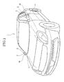
- FIG.1 is the perspective view showing a state where door mirror devices as outer mirrors for vehicle, each of which is provided with a lighting device for vehicle according to an embodiment of the present invention, are erected to a vehicle body.
- reference numeral 1 denotes a vehicle body
- 2 denotes a door mirror as an outer mirror for vehicle.
- the door mirror 2 has a lighting device including a housing body 3 which is configured to hold the door mirror 2 for rear viewing as shown in FIG.2 in an enlarged manner.
- the door mirror 2 is designed to be turnable between an erected state and a retracted state to the vehicle body 1.
- the housing body 3 has a shape curved backwardly (arrow A direction) from an inner end portion toward an outer end portion in a width direction of the vehicle body 1 at a rear surface side of the mirror 4 in an erected state.
- a base member 5 is provided inside the housing body 3. Positioning members 6 are provided with appropriate intervals on the base member 5 from the outer end portion toward the inner end portion in the width direction of the vehicle body 1.
- a circuit board 7 is provided on the positioning member 6. The circuit board 7 is positioned by the positioning member 6 and fixed on the base member 5 by a presser bar spring 8 and a locking screw 9.
- Light-emitting diodes (LED) 10 as light emitting devices are provided for the circuit board 7. The light-emitting diodes 10 arc arrayed from the outer end portion toward the inner end portion in the width direction of the vehicle body 1.
- An outer lens 11 as an outer member exposed on the rear surface side of the housing body 3 is provided on the base member 5.
- a decorating wall 12 is provided between the base member 5 and the outer lens 11.
- the decorating wall 12 is formed by resin molding, for example.
- Each of the light-emitting diodes 10 is arranged between the base member 5 and the decorating wall 12.
- a light transmitting portion 13 is formed on an area of the decorating wall 12 so as to face a light emission portion 10a of the light emitting diode 10.
- positioning peripheral walls 15, for example in a cylindrical shape, which position mask members 14 to prevent attachment of deposited matter on the light transmitting portions 13 when performing deposition are formed so as to surround the light transmitting portion 13 corresponding to the outer end portion in the width direction of the vehicle body 1 and residual light transmitting portions 13.
- a deposited surface is provided on at least one surface of the decorating wall excluding areas of the light transmitting portions.
- the deposited surface may be provided on a surface of the decorating wall, which faces the housing body or the outer lens, as well as provided on both surfaces.
- the deposited surface 12a which carries out decorating action when visually contacted from outside through the lens is formed on the surface facing the outer lens 11 and excluding areas of the light transmitting portions 13.
- Each light-emitting diode 10 is configured to output direct light P1, P2, P3 (see FIG.4) through the light transmitting portions 13 and the outer lens 11 in an angle range directing backward from the width direction of the vehicle body 1 so as to be visually contacted as one light source when simultaneously turned ON in the erected state of the housing body 3.
- direct light P1 and direct light P2 is used as light for turn signal.
- the decorating wall has a plurality of wall sections 112 on each of which the light transmitting portion is provided.
- the wall sections 112 have different inclinations from each other and are disposed to set light from the light emitting devices within the range of the predetermined light distribution angle.
- the decorating wall 12 is configured to have different structures of the light transmitting portion 13 depending on regions.
- the decorating wall 12 is manufactured via a manufacturing process described below, for example.
- a mold die is provided on a mold cavity (not shown) such that a transparent flat plate corresponding to the light transmitting portions 13 is obtained.
- a molded component having a shape corresponding to the decorating wall 12 is formed.
- the transparent flat plate of the molded component is masked by the mask members 14 shown in FIG.3. Then, aluminization is applied to at least one surface of the molded component excluding the masked areas of the transparent flat plate by using a deposition apparatus (not shown) to form the deposited surface 12a.
- the mask members 14 are removed from the molded component. Consequently, the decorating wall 12 where the light transmitting portions 13 are made of transparent flat plate and which has the deposited surface 12a is formed.
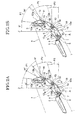
- the lighting device for vehicle 16 When a lighting device for vehicle 16 is manufactured by using the decorating wall 12, the lighting device for vehicle 16 corresponding to the region where the range of the light distribution angle is set from approximately 30 degrees to approximately 70 degrees in relation to the front-rear direction of the vehicle body 1 as a reference direction Z is obtained as shown in FIG.2A.
- a mold die to form a prism surface (not shown) is provided on the cavity of mold such that the prism surface is obtained in areas corresponding to the light transmitting portions 13 as light distribution windows. Consequently, a molded component having the shape corresponding to the decorating wall 12 is formed.
- the prism surface of the molded component is masked by the mask members 14.
- aluminization is applied to on the surface of the molded component excluding areas of the prism surface by using the deposition apparatus (not shown) to form the deposited surface 12a.
- the lighting device for vehicle 16 When the lighting device for vehicle 16 is manufactured by using the decorating wall 12, the lighting device for vehicle 16 corresponding to the region where the range of the light distribution angle is set from approximately 5 degrees to approximately 55 degrees in relation to the front-rear direction of the vehicle as a reference direction Z is obtained as shown in FIG.2B.
- the lighting device for vehicle 16 capable of flexibly being adjusted to regulations of each area having a different range of the distribution angle can be inexpensively manufactured. Furthermore, since the light-emitting diode 10 cannot be visually contacted directly via the outer lens 11, a decorating function can be improved by making light-emitting diodes become difficult to visually contact from outside.
- the configuration for manufacturing the lighting device for vehicle 16 capable of flexibly being adjusted to regulations of each area having a different range of the light distribution angle by forming the transparent flat plate or the prism surface on the light transmitting portions 13 of the decorating wall 12, is employed.
- the lighting device for vehicle is also capable of improving the decorating function by making light-emitting diodes become difficult to visually contact from outside.
- a configuration having the shape described below can be also employed as the decorating wall.
- the decorating wall 12 has openings 17 as the light transmitting portions 13 and positioning protrusions 18 as shown in FIG.4A.
- a mold die to form the openings 17 (not shown) and a mold die to form the positioning protrusions 18 (not shown) are provided on a cavity to form the decorating wall 12. Consequently, the molded component of the decorating wall 12 is formed.
- aluminization is applied to the surface of the decorating wall 12 excluding areas of the openings 17 by using the deposition apparatus (not shown) to form the deposited surface 12a. Consequently, the decorating wall 12 having the openings 17 and the positioning protrusions 18 is manufactured.
- the openings 17 themselves are used as the light transmitting portions 13. Furthermore, a specific prism body may be fixed to the openings 17.
- a prism body 19 which deflects light beam shown in FIG.4C is previously prepared by molding.
- the prism body 19 has a prism portion 19a and an attaching portion 19b.
- An attaching hole 19c to be fitted into the protrusion 18 is formed on the attaching portion 19b.
- the same mold in a case of manufacturing the lighting device for vehicle 16 corresponding to regulations having a different range of the light distribution angle depending on each area, the same mold can be used as a mode to be used in molding the decorating wall 12.
- the prism body 19 When the prism body 19 is installed to the opening 17 of the decorating wall 12, which is molded in the above-described manner, the range of the light distribution angle of the lighting device for vehicle 16 can be varied. Furthermore, even in a case where the regulations are changed, simply preparing the prism body 19 having a different refraction angle can adjust to the change. Therefore, the invention can flexibly be adjusted to the changes of regulations.
- the lighting device 16 capable of flexibly being adjusted to regulations of each area having a different range of the light distribution angle and capable of improving a decorating function by making the light-emitting diodes 10 become difficult to visually contact from outside.
- the configuration where the prism body is fixed to the opening 17 can be applied for the regulations of North America, and according to Example 2, the degree of freedom of the light distribution settings remarkably increases.
- an effect being capable of flexibly being adjusted to regulations of each area having a different range of a light distribution angle and making light-emitting diodes become difficult to visually contact from outside to improve the decorating function is exerted.
Landscapes
- Engineering & Computer Science (AREA)
- Mechanical Engineering (AREA)
- Multimedia (AREA)
- Lighting Device Outwards From Vehicle And Optical Signal (AREA)
- Non-Portable Lighting Devices Or Systems Thereof (AREA)
- Rear-View Mirror Devices That Are Mounted On The Exterior Of The Vehicle (AREA)
Abstract
Description
- The present invention relates to a lighting device for vehicle used in an outer mirror for vehicle, particularly to a lighting device for vehicle preferably used in a door mirror device.
- Conventionally, there is known a lighting device for vehicle provided on a housing body which constitutes a part of a door mirror device as an outer mirror. In the lighting device, a plurality of light-emitting diodes (LED) as light emitting devices are provided on an outer end portion of the housing body in a width direction of a vehicle (vehicle width direction) and disposed with intervals in a horizontal direction. The lighting device for vehicle is used as a signal lamp to let following cars or the like to perceive right turn or left turn by simultaneously turning ON the plurality of light-emitting diodes (refer to
Japanese Patent Laid-open No.2002-79885 - Further, vehicle regulations provide that the plurality of light-emitting diodes should be recognized as one light source when they are turned ON.
- Furthermore, it is known that there is also a lighting device for vehicle where a plurality of light-emitting diodes are provided in a row with intervals in a horizontal direction from the outer end portion toward the inner end portion of the housing body in the vehicle width direction. In the above lighting device for vehicle, a plurality of light-emitting diodes provided on the outer end portion in the vehicle width direction are used as signal lamps and light-emitting diodes provided on the inner end portion in the vehicle width direction are used as ornament lamps.
- For the lighting device for vehicle as well, regulations provide that the plurality of light emitting diodes arranged in a row should be recognized as one light source when they are turned ON.
- Furthermore, as the lighting device for vehicle, a lighting device for vehicle configured such that an outer lens is provided for the housing body and the inside of the lighting device for vehicle is seen through the outer lens is also known.
- Incidentally, in this type of the lighting device for vehicle where the inside is seen from outside, since the inside of the lighting device for vehicle is seen through the outer lens even when the light-emitting diodes are not turned ON, there is an inconvenience that a decorating characteristic reduces.
- Thus, an idea that a reflector reflecting output light from the light-emitting diodes and leading to the outer lens is provided between the housing body and the outer lens and the reflector is allowed to function as a decorating wall.
- However, in the regulations, when the plurality of light-emitting diodes are simultaneously turned ON, a positional relation between the light-emitting diode and the reflector is specified such that irradiated regions formed on the inside surface of the outer lens by the output light reflected by the reflector become adjacent to each other with intervals, each of which is set to a predetermined interval or less.
- This is because, according to the legal standard of Europe, only a single lighting device is admitted to be mounted on the door mirror device, and if a plurality of light-emitting diodes are used as a light source in the lighting device, the adjacent irradiated regions should have intervals, each of which is a predetermined gap or less.
- On the other hand, legal standard of a light distribution angle range for a side turn lamp is different by each area, For example, in European region, the angle range is from approximately 5 degrees to approximately 60 degrees in relation to a front-rear direction of a vehicle as a reference direction. On the contrary, in North American region, the angle range is set from approximately 30 degrees to approximately 70 degrees. This is because an angle formed by light beam on a rear end side of irradiated light which is irradiated outwardly from the lighting device and the vehicle front-rear direction is required to be an angle of a predetermined angle or less, that is, 5 degrees or less in Europe and 30 degrees or less in the U.S.
- In the case of the lighting device for vehicle having the reflector which reflects output light from the light-emitting diodes and leads to the outer lens, if the reflector is allowed to function as the decorating wall, the shape of the reflector needs to be devised depending on each area because the legal standard is different depending on each area. For this reason, the lighting device for vehicle having the reflector has an inconvenience that the degree of freedom in design is poor and lacks flexibility in design.
- Furthermore, in this type of lighting device for vehicle in which the inside is seen through the outer lens also has an inconvenience that a decorating characteristic reduces since the light-emitting diodes are seen from outside through the outer lens.
- An object of the present invention is to provide a lighting device which is capable of flexibly being adjusted to regulations of each area having a different range of a light distribution angle and capable of improving a decorating function by making light-emitting diodes become difficult to visually contact from outside, and a door mirror device using the lighting device.
- To achieve the above object, a lighting device according to an embodiment of the present invention includes a housing body, an outer member provided on the housing body, a decorating wall provided between the housing body and the outer member and a plurality of light emitting devices which are provided between the housing body and the decorating wall and disposed with intervals to each other. The decorating wall includes a plurality of light transmitting portions, each of which is disposed to face each of the plurality of light emitting devices. The light transmitting portion is disposed to set light emitted from the corresponding light emitting device within a range of a predetermined light distribution angle.
-
- FIG.1 is a perspective view for describing a vehicle having door mirrors provided with a lighting device for vehicle according to an embodiment of the present invention.
- FIG.2A is an explanatory view of Example 1 of a lighting device for vehicle according to the present invention, in which a range of a light distribution angle is set from 30 degrees to 70 degrees.
- FIG.2B is an explanatory view of Example 1 of a lighting device for vehicle according to the present invention, in which a range of a light distribution angle is set from 5 degrees to 55 degrees.
- FIG.3 is a partially perspective view showing an external shape of a decorating wall according to an embodiment of the present invention.
- FIG.4A is a partially enlarged sectional view of a lighting device for vehicle for illustrating Example 2 of a lighting device for vehicle according to the present invention, in which a light transmitting portion includes an opening.
- FIG.4B is a partially enlarged sectional view of a lighting device for vehicle in which a prism is disposed on the opening of the decorating wall shown in FIG.4A.
- FIG.4C is a perspective view of the prism shown in FIG.4B.
- FIG.5A is an explanatory view showing another example of a lighting device for vehicle according to the present invention, in which a range of a light distribution angle is set from 30 degrees to 70 degrees.
- FIG.5B is a sectional view for illustrating a lighting device for vehicle in which a range of a light distribution angle is set from 5 degrees to 55 degrees.
- Descriptions will be made for examples of a lighting device for vehicle according to the present invention with reference to the drawings as follows.
- A lighting device according to an embodiment of the present invention includes a housing body, an outer member such as an outer lens provided on the housing body, a decorating wall provided between the housing body and the outer lens and a plurality of light emitting devices which are provided between the housing body and the decorating wall and disposed with intervals to each other. The decorating wall includes a plurality of light transmitting portions, each of which is disposed to face each of the plurality of light emitting devices. The light transmitting portion is disposed to set light emitted from the corresponding light emitting device within a range of a predetermined light distribution angle.
- The light transmitting portion may be provided separately from or integrated with the decorating wall. The light transmission portion may be a flat plane, an opening, a prism, a convex lens, or the like. In the case of the opening, a prism may be disposed in the opening. The prism, the convex lens, or the like may be configured to change the range of the light distribution angle. A positioning peripheral wall which positions a mask member on the light transmitting portion may be formed on a circumference of each of the light transmitting portions.
- A lighting device according to an embodiment of the present invention may be used in a door mirror device (door mirror) as an outer mirror. FIG.1 is the perspective view showing a state where door mirror devices as outer mirrors for vehicle, each of which is provided with a lighting device for vehicle according to an embodiment of the present invention, are erected to a vehicle body.
- In FIG.1,
reference numeral 1 denotes a vehicle body, and 2 denotes a door mirror as an outer mirror for vehicle. Thedoor mirror 2 has a lighting device including ahousing body 3 which is configured to hold thedoor mirror 2 for rear viewing as shown in FIG.2 in an enlarged manner. Thedoor mirror 2 is designed to be turnable between an erected state and a retracted state to thevehicle body 1. - The
housing body 3 has a shape curved backwardly (arrow A direction) from an inner end portion toward an outer end portion in a width direction of thevehicle body 1 at a rear surface side of themirror 4 in an erected state. - A
base member 5 is provided inside thehousing body 3. Positioningmembers 6 are provided with appropriate intervals on thebase member 5 from the outer end portion toward the inner end portion in the width direction of thevehicle body 1. Acircuit board 7 is provided on thepositioning member 6. Thecircuit board 7 is positioned by thepositioning member 6 and fixed on thebase member 5 by apresser bar spring 8 and alocking screw 9. Light-emitting diodes (LED) 10 as light emitting devices are provided for thecircuit board 7. The light-emittingdiodes 10 arc arrayed from the outer end portion toward the inner end portion in the width direction of thevehicle body 1. - An
outer lens 11 as an outer member exposed on the rear surface side of thehousing body 3 is provided on thebase member 5. A decoratingwall 12 is provided between thebase member 5 and theouter lens 11. The decoratingwall 12 is formed by resin molding, for example. - Each of the light-
emitting diodes 10 is arranged between thebase member 5 and thedecorating wall 12. Alight transmitting portion 13 is formed on an area of the decoratingwall 12 so as to face alight emission portion 10a of thelight emitting diode 10. - On the decorating
wall 12, as shown in FIG.3, positioningperipheral walls 15, for example in a cylindrical shape, whichposition mask members 14 to prevent attachment of deposited matter on thelight transmitting portions 13 when performing deposition are formed so as to surround thelight transmitting portion 13 corresponding to the outer end portion in the width direction of thevehicle body 1 and residuallight transmitting portions 13. - A deposited surface is provided on at least one surface of the decorating wall excluding areas of the light transmitting portions. The deposited surface may be provided on a surface of the decorating wall, which faces the housing body or the outer lens, as well as provided on both surfaces.
- The deposited
surface 12a which carries out decorating action when visually contacted from outside through the lens is formed on the surface facing theouter lens 11 and excluding areas of thelight transmitting portions 13. - Each light-emitting
diode 10 is configured to output direct light P1, P2, P3 (see FIG.4) through thelight transmitting portions 13 and theouter lens 11 in an angle range directing backward from the width direction of thevehicle body 1 so as to be visually contacted as one light source when simultaneously turned ON in the erected state of thehousing body 3. Herein, a part of direct light P1 and direct light P2 is used as light for turn signal. - The decorating wall has a plurality of
wall sections 112 on each of which the light transmitting portion is provided. Thewall sections 112 have different inclinations from each other and are disposed to set light from the light emitting devices within the range of the predetermined light distribution angle. Thedecorating wall 12 is configured to have different structures of thelight transmitting portion 13 depending on regions. Thedecorating wall 12 is manufactured via a manufacturing process described below, for example. - For example, in a case where a range of a light distribution angle provided in the regulations is from approximately 30 degrees to approximately 70 degrees in relation to the front-rear direction of a vehicle as a reference direction Z, a mold die is provided on a mold cavity (not shown) such that a transparent flat plate corresponding to the
light transmitting portions 13 is obtained. Thus, a molded component having a shape corresponding to thedecorating wall 12 is formed. - Next, the transparent flat plate of the molded component is masked by the
mask members 14 shown in FIG.3. Then, aluminization is applied to at least one surface of the molded component excluding the masked areas of the transparent flat plate by using a deposition apparatus (not shown) to form the depositedsurface 12a. - Then, the
mask members 14 are removed from the molded component. Consequently, thedecorating wall 12 where thelight transmitting portions 13 are made of transparent flat plate and which has the depositedsurface 12a is formed. - When a lighting device for
vehicle 16 is manufactured by using thedecorating wall 12, the lighting device forvehicle 16 corresponding to the region where the range of the light distribution angle is set from approximately 30 degrees to approximately 70 degrees in relation to the front-rear direction of thevehicle body 1 as a reference direction Z is obtained as shown in FIG.2A. - Furthermore, for example, in a case where the range of the light distribution angle provided in the regulations is set from approximately 5 degrees to approximately 55 degrees in relation to the front-rear direction of the vehicle as a reference direction Z, a mold die to form a prism surface (not shown) is provided on the cavity of mold such that the prism surface is obtained in areas corresponding to the
light transmitting portions 13 as light distribution windows. Consequently, a molded component having the shape corresponding to thedecorating wall 12 is formed. - Next, the prism surface of the molded component is masked by the
mask members 14. Next, aluminization is applied to on the surface of the molded component excluding areas of the prism surface by using the deposition apparatus (not shown) to form the depositedsurface 12a. - Next,
mask members 14 are removed from the molded component. Consequently, thedecorating wall 12 where thelight transmitting portions 13 are made of the prism surface and which has the depositedsurface 12a is formed. - When the lighting device for
vehicle 16 is manufactured by using thedecorating wall 12, the lighting device forvehicle 16 corresponding to the region where the range of the light distribution angle is set from approximately 5 degrees to approximately 55 degrees in relation to the front-rear direction of the vehicle as a reference direction Z is obtained as shown in FIG.2B. - According to an example of the invention, by a slight change in a molding process which is replacing a mold die, the lighting device for
vehicle 16 capable of flexibly being adjusted to regulations of each area having a different range of the distribution angle can be inexpensively manufactured. Furthermore, since the light-emittingdiode 10 cannot be visually contacted directly via theouter lens 11, a decorating function can be improved by making light-emitting diodes become difficult to visually contact from outside. - In the above Example 1, the configuration for manufacturing the lighting device for
vehicle 16 capable of flexibly being adjusted to regulations of each area having a different range of the light distribution angle by forming the transparent flat plate or the prism surface on thelight transmitting portions 13 of thedecorating wall 12, is employed. The lighting device for vehicle is also capable of improving the decorating function by making light-emitting diodes become difficult to visually contact from outside. However, a configuration having the shape described below can be also employed as the decorating wall. - Herein, the
decorating wall 12 hasopenings 17 as thelight transmitting portions 13 andpositioning protrusions 18 as shown in FIG.4A. A mold die to form the openings 17 (not shown) and a mold die to form the positioning protrusions 18 (not shown) are provided on a cavity to form thedecorating wall 12. Consequently, the molded component of thedecorating wall 12 is formed. Next, aluminization is applied to the surface of thedecorating wall 12 excluding areas of theopenings 17 by using the deposition apparatus (not shown) to form the depositedsurface 12a. Consequently, thedecorating wall 12 having theopenings 17 and thepositioning protrusions 18 is manufactured. - Since the configuration of the
base member 5, the configuration of theouter lens 11 and the residual configuration of thedecorating wall 12 are similar to the configuration shown in FIG.2, their detailed description will be omitted. - Then, in a case where the range of the light distribution angle provided in the regulations is set from approximately 30 degrees to approximately 70 degrees in relation to the front-rear direction of the vehicle as a reference direction Z (see FIG.5A), the
openings 17 themselves are used as thelight transmitting portions 13. Furthermore, a specific prism body may be fixed to theopenings 17. - Furthermore, in a case where the range of the light distribution angle provided in the regulations is set from approximately 5 degrees to approximately 55 degrees in relation to the front-rear direction of the vehicle as a reference direction Z (see FIG.5B), a
prism body 19 which deflects light beam shown in FIG.4C is previously prepared by molding. - The
prism body 19 has aprism portion 19a and an attaching portion 19b. An attachinghole 19c to be fitted into theprotrusion 18 is formed on the attaching portion 19b. Then, in a case of manufacturing the lighting device for vehicle in which the range of the light distribution angle provided in the regulations is set from approximately 5 degrees to approximately 55 degrees in relation to the front-rear direction of the vehicle as a reference direction Z, theprism portion 19a of theprism body 19 is fitted with theopening 17 and theprotrusion 18 is fitted with the attachinghole 19c, and theprism body 19 is fixed to thedecorating wall 12 as shown in FIG.4B. - With the above configurations, in a case where the range of the light distribution angle provided in the regulations is set from approximately 5 degrees to approximately 55 degrees in relation to the front-rear direction of the vehicle as a reference direction Z, light beam outputted at the angle range from approximately 30 degrees to approximately 70 degrees can be deflected by the
prism body 19 as shown in FIG.5B. - According to an example of the invention, in a case of manufacturing the lighting device for
vehicle 16 corresponding to regulations having a different range of the light distribution angle depending on each area, the same mold can be used as a mode to be used in molding thedecorating wall 12. - When the
prism body 19 is installed to theopening 17 of thedecorating wall 12, which is molded in the above-described manner, the range of the light distribution angle of the lighting device forvehicle 16 can be varied. Furthermore, even in a case where the regulations are changed, simply preparing theprism body 19 having a different refraction angle can adjust to the change. Therefore, the invention can flexibly be adjusted to the changes of regulations. - Specifically, by the slight change of a process which is attaching and detaching or replacing of the
prism body 19, it becomes possible to inexpensively manufacture thelighting device 16 capable of flexibly being adjusted to regulations of each area having a different range of the light distribution angle and capable of improving a decorating function by making the light-emittingdiodes 10 become difficult to visually contact from outside. - The configuration where the prism body is fixed to the
opening 17 can be applied for the regulations of North America, and according to Example 2, the degree of freedom of the light distribution settings remarkably increases. - Although the present invention has been described in terms of exemplary embodiments, it is not limited thereto. It should be appreciated that variations may be made in the embodiments described by persons skilled in the art without departing from the scope of the present invention as defined by the following claims.
- According to the present invention, an effect being capable of flexibly being adjusted to regulations of each area having a different range of a light distribution angle and making light-emitting diodes become difficult to visually contact from outside to improve the decorating function is exerted.
Claims (20)
- A lighting device (16) for vehicle, comprisinga housing body (3);an outer lens (11) provided on the housing body;a decorating wall (12) provided between the housing body and the outer lens; anda plurality of light emitting devices (10) which are provided between the housing body and the decorating wall and disposed with intervals to each other,wherein the decorating wall includes a plurality of light transmitting portions (13), each of which is disposed to face each of the plurality of light emitting devices; and
the light transmitting portion is disposed to set light emitted from the corresponding light emitting device within a range of a predetermined light distribution angle. - The lighting device according to claim 1, wherein each of the light transmitting portions of the decorating wall includes an opening (17).
- The lighting device according to claim 2, wherein a prism (19) is disposed in the opening to change the range of the light distribution angle.
- The lighting device according to claim 1, wherein each of the light transmitting portion of the decorating wall includes a prism integrated with the decorating wall and disposed to change the range of the light distribution angle.
- The lighting device according to claim 1, wherein each of the light transmitting portion of the decorating wall includes a convex lens disposed to change the range of the light distribution angle.
- The lighting device according to claim 2, wherein a positioning peripheral wall (15) which positions a mask member (14) on the light transmitting portion is formed on a circumference of each of the light transmitting portions.
- The lighting device according to claim 4, wherein a positioning peripheral wall (15) which positions a mask member (14) on the light transmitting portion is formed on a circumference of each of the light transmitting portions.
- The lighting device according to claim 5, wherein a positioning peripheral wall (15) which positions a mask member (14) on the light transmitting portion is formed on a circumference of each of the light transmitting portions.
- The lighting device according to claim 1, which is disposed both end portions of a vehicle (1) in a width direction of the vehicle, wherein
the housing body has a base member (5) on which positioning members (6) are disposed with intervals to each other in the width direction
a circuit board (7) is positioned by each of the positioning member and fixed on the base portion; and
each of the light emitting device is provided on each of the circuit board. - The lighting device according to claim 1, wherein the decorating wall is formed by resin molding and the light transmitting portion is formed by molding using a mold die configured to form a transparent flat plate.
- The lighting device according to claim 1, wherein the decorating wall is formed by resin molding and the light transmitting portion is formed by molding using a mold die configured to form a prism.
- The lighting device according to claim 1, which is disposed both end portions of a vehicle (1) in a width direction of the vehicle,
wherein the range of the predetermined light distribution angle is from 5 degrees to 55 degrees in relation to a front-rear direction of the vehicle. - The lighting device according to claim 1, which is disposed both end portions of a vehicle (1) in a width direction of the vehicle,
wherein the range of the predetermined light distribution angle is from 30 degrees to 70 degrees in relation to a front-rear direction of the vehicle. - The lighting device according to claim 1, wherein the decorating wall includes a deposited surface (12a) provided on at least one surface of the decorating wall excluding area of the light transmitting portions.
- The lighting device according to claim 1, wherein
the decorating wall has a plurality of wall sections (112) which have different inclinations from each other, and
the wall sections are disposed to set light from the light emitting devices within the range of the predetermined light distribution angle. - A lighting device (16) for vehicle, comprising:a housing body (3);an outer lens (11) provided on the housing body;a decorating wall (12) provided between the housing body and the outer lens; anda plurality of light emitting devices (10) which are provided between the housing body and the decorating wall and disposed with intervals to each other,wherein the decorating wall includes a plurality of light transmitting portions (13), each of which is disposed to face each of the plurality of light emitting devices and a deposited surface (12a) provided on at least one surface of the decorating wall excluding area of the light transmitting portions.
- The lighting device according to claim 16, wherein the deposited surface is provided on a surface of the decorating wall, which faces the outer lens.
- The lighting device according to claim 16, wherein the deposited surface is provided on a surface of the decorating wall, which faces the housing body.
- A door mirror device (2) having the lighting device for vehicle according to claim 1 and a mirror (4) which is hold by the housing body of the lighting device.
- A door mirror device (2) having the lighting device for vehicle according to claim 16 and a mirror (4) which is hold by the housing body of the lighting device.
Applications Claiming Priority (1)
| Application Number | Priority Date | Filing Date | Title |
|---|---|---|---|
| JP2006298598A JP4631840B2 (en) | 2006-11-02 | 2006-11-02 | Vehicle lighting |
Publications (3)
| Publication Number | Publication Date |
|---|---|
| EP1918159A2 true EP1918159A2 (en) | 2008-05-07 |
| EP1918159A3 EP1918159A3 (en) | 2008-06-11 |
| EP1918159B1 EP1918159B1 (en) | 2010-08-25 |
Family
ID=38781431
Family Applications (1)
| Application Number | Title | Priority Date | Filing Date |
|---|---|---|---|
| EP07119577A Not-in-force EP1918159B1 (en) | 2006-11-02 | 2007-10-30 | Lighting device for vehicle and door mirror device |
Country Status (6)
| Country | Link |
|---|---|
| US (1) | US7677776B2 (en) |
| EP (1) | EP1918159B1 (en) |
| JP (1) | JP4631840B2 (en) |
| KR (1) | KR100959551B1 (en) |
| CN (1) | CN101173745B (en) |
| DE (1) | DE602007008661D1 (en) |
Cited By (1)
| Publication number | Priority date | Publication date | Assignee | Title |
|---|---|---|---|---|
| EP2277741A1 (en) * | 2009-07-20 | 2011-01-26 | SMR Patents S.à.r.l. | Light guide turn signal indicator rear view mirror |
Families Citing this family (6)
| Publication number | Priority date | Publication date | Assignee | Title |
|---|---|---|---|---|
| JP4597082B2 (en) * | 2006-03-22 | 2010-12-15 | 株式会社ミツバ | Vehicle housing |
| KR101283196B1 (en) * | 2010-12-01 | 2013-07-05 | 기아자동차주식회사 | Turn signal lamp for outside mirror |
| JP5906050B2 (en) | 2011-09-30 | 2016-04-20 | 株式会社小糸製作所 | Vehicle lighting |
| DE102016114353A1 (en) * | 2016-08-03 | 2018-02-08 | Daimler Ag | End cap for an illuminated trim strip arrangement and trim strip arrangement |
| CN107878353A (en) * | 2016-09-30 | 2018-04-06 | 上汽通用汽车有限公司 | Lens and its installation method |
| JP2024158524A (en) * | 2023-04-27 | 2024-11-08 | 美里工業株式会社 | Vehicle door mirror and manufacturing method thereof |
Family Cites Families (33)
| Publication number | Priority date | Publication date | Assignee | Title |
|---|---|---|---|---|
| JPH0388220U (en) * | 1989-12-25 | 1991-09-10 | ||
| US5278731A (en) * | 1992-09-10 | 1994-01-11 | General Electric Company | Fiber optic lighting system using conventional headlamp structures |
| FR2707223B1 (en) * | 1993-07-07 | 1995-09-29 | Valeo Vision | Improved signaling light with light-emitting diodes. |
| DE4417695C2 (en) * | 1994-05-20 | 1998-01-29 | Reitter & Schefenacker Gmbh | Motor vehicle light |
| JPH09306219A (en) * | 1996-05-13 | 1997-11-28 | Yamaha Motor Co Ltd | Headlight device |
| DE29702746U1 (en) * | 1997-02-18 | 1997-04-03 | Reitter & Schefenacker GmbH & Co. KG, 73730 Esslingen | Exterior rear view mirror for vehicles, preferably for motor vehicles |
| FR2776595B1 (en) * | 1998-03-31 | 2000-06-16 | Valeo Vision | SIGNAL LIGHT COMPRISING MULTIPLE LIGHT SOURCES |
| EP0972677A3 (en) | 1998-07-17 | 2000-12-20 | Hella KG Hueck & Co. | Vehicle lighting |
| DE19933724A1 (en) | 1999-07-19 | 2001-02-01 | Fer Fahrzeugelektrik Gmbh | Side flashing light |
| EP1077344A3 (en) | 1999-08-16 | 2004-01-28 | FER Fahrzeugelektrik GmbH | Lamp |
| EP1118813B1 (en) * | 2000-01-21 | 2008-10-08 | Stanley Electric Co., Ltd. | Automobile signal lamp |
| DE20001407U1 (en) * | 2000-01-27 | 2000-03-16 | Reitter & Schefenacker GmbH & Co. KG, 73730 Esslingen | Exterior rear view mirror for vehicles, preferably for motor vehicles |
| ES2168071B1 (en) * | 2000-07-12 | 2003-07-16 | Barros Alejandro Rodriguez | MODULAR REAR VIEW MIRROR WITH INTERCHANGEABLE MULTIPLE SIGNALS FOR VEHICLES OF 2, 3, 4 OR MORE WHEELS. |
| JP2002075025A (en) * | 2000-08-25 | 2002-03-15 | Stanley Electric Co Ltd | Led lighting fixture for vehicle |
| JP4144170B2 (en) | 2000-09-08 | 2008-09-03 | 市光工業株式会社 | Side turn lamp for door mirror |
| ES2278670T3 (en) * | 2000-10-04 | 2007-08-16 | Fer Fahrzeugelektrik Gmbh | INTERMITTENT LATERAL LIGHT. |
| FR2820273B1 (en) * | 2001-01-29 | 2006-07-28 | Koito Mfg Co Ltd | PHOTOEMISSIVE DIODE AND DIODE LAMP FOR AUTOMOBILE |
| MXPA03008637A (en) * | 2001-03-27 | 2005-03-07 | Meridian Automotive Sys Inc | Vehicular lamp assembly with a simplified structure and chmsl and tail lamp incorporating the same. |
| JP2002362222A (en) * | 2001-05-31 | 2002-12-18 | Tokai Rika Co Ltd | Visor cover structure having turn signal of outer mirror |
| US6637921B2 (en) * | 2001-09-28 | 2003-10-28 | Osram Sylvania Inc. | Replaceable LED bulb with interchangeable lens optic |
| US6846100B2 (en) | 2002-02-25 | 2005-01-25 | Norifumi Imazeki | Lighting fixture for vehicles |
| JP3998999B2 (en) | 2002-03-06 | 2007-10-31 | 株式会社小糸製作所 | Vehicle lighting |
| US6769798B2 (en) * | 2002-04-11 | 2004-08-03 | E'sam Co.,. Ltd. | Side mirror cover and cover lamp to be used therefor |
| JP2004210236A (en) * | 2003-01-08 | 2004-07-29 | Ichikoh Ind Ltd | Outer mirror housing and outer mirror cover |
| JP4110989B2 (en) * | 2003-02-03 | 2008-07-02 | 市光工業株式会社 | Outside mirror device with lamp |
| US6758582B1 (en) * | 2003-03-19 | 2004-07-06 | Elumina Technology Incorporation | LED lighting device |
| JP2005067391A (en) * | 2003-08-25 | 2005-03-17 | Sakae Riken Kogyo Co Ltd | Door mirror device with turn signal lamp |
| JP2005190716A (en) * | 2003-12-24 | 2005-07-14 | Ichikoh Ind Ltd | Outside mirror device for vehicle |
| JP4239839B2 (en) * | 2004-02-02 | 2009-03-18 | 市光工業株式会社 | Outside mirror device for vehicle |
| US7513664B2 (en) * | 2004-05-10 | 2009-04-07 | Ichikoh Industries, Ltd. | Outside mirror apparatus including lighting device for vehicle |
| JP4218611B2 (en) * | 2004-08-06 | 2009-02-04 | 市光工業株式会社 | Vehicle lamp, vehicle outside mirror device with vehicle lamp |
| JP4413764B2 (en) * | 2004-12-10 | 2010-02-10 | 株式会社小糸製作所 | Vehicle lighting |
| DE102005012104A1 (en) | 2005-03-10 | 2006-09-14 | Schefenacker Vision Systems Germany Gmbh | Housing, in particular mirror housing |
-
2006
- 2006-11-02 JP JP2006298598A patent/JP4631840B2/en not_active Expired - Fee Related
-
2007
- 2007-08-23 CN CN2007101466494A patent/CN101173745B/en not_active Expired - Fee Related
- 2007-09-03 KR KR1020070088953A patent/KR100959551B1/en not_active Expired - Fee Related
- 2007-10-29 US US11/926,408 patent/US7677776B2/en not_active Expired - Fee Related
- 2007-10-30 DE DE602007008661T patent/DE602007008661D1/en active Active
- 2007-10-30 EP EP07119577A patent/EP1918159B1/en not_active Not-in-force
Cited By (2)
| Publication number | Priority date | Publication date | Assignee | Title |
|---|---|---|---|---|
| EP2277741A1 (en) * | 2009-07-20 | 2011-01-26 | SMR Patents S.à.r.l. | Light guide turn signal indicator rear view mirror |
| US8177401B2 (en) | 2009-07-20 | 2012-05-15 | Smr Patents S.A.R.L. | Light guide turn signal indicator rear view mirror |
Also Published As
| Publication number | Publication date |
|---|---|
| CN101173745B (en) | 2011-05-18 |
| EP1918159A3 (en) | 2008-06-11 |
| US7677776B2 (en) | 2010-03-16 |
| EP1918159B1 (en) | 2010-08-25 |
| JP4631840B2 (en) | 2011-02-16 |
| KR100959551B1 (en) | 2010-05-27 |
| JP2008114677A (en) | 2008-05-22 |
| KR20080040559A (en) | 2008-05-08 |
| CN101173745A (en) | 2008-05-07 |
| US20080259624A1 (en) | 2008-10-23 |
| DE602007008661D1 (en) | 2010-10-07 |
Similar Documents
| Publication | Publication Date | Title |
|---|---|---|
| EP1918159B1 (en) | Lighting device for vehicle and door mirror device | |
| US8382351B2 (en) | Vehicle lamp | |
| US6499870B1 (en) | Tail light for a motor vehicle | |
| EP2377720B1 (en) | Light guide device for automotive use | |
| US6746634B2 (en) | Vehicular lamp and injection mold and manufacturing method for lamp body of vehicular lamp | |
| US7220030B2 (en) | Exterior mirror having lamp and exterior rear-view mirror having lamp | |
| EP3599418B1 (en) | Vehicular lamp comprising a light guide | |
| EP0922903B1 (en) | Automobile rear combination lamp | |
| WO2023046275A1 (en) | Self-illuminated frontend panel for a vehicle | |
| CN111868435B (en) | Lighting device for vehicle | |
| CN114207349A (en) | Lighting device for vehicle | |
| EP1559614B1 (en) | Outside mirror apparatus for vehicle and illuminating unit for the outside mirror apparatus | |
| CN118251569A (en) | Light module for a lighting device of a vehicle | |
| JP5060879B2 (en) | Vehicle interior light | |
| US10391930B2 (en) | Vehicular lamp and vehicular exterior rear view device | |
| CN217329634U (en) | Car light optical structure and have its vehicle | |
| JP7666892B2 (en) | BSM unit | |
| EP3561374B1 (en) | Vehicular lamp | |
| JPH08125218A (en) | Optical semiconductor device | |
| CN218367589U (en) | Rearview mirror indicator lamp housing, rearview mirror indicator lamp, rearview mirror and vehicle | |
| JP7491754B2 (en) | Vehicle Lighting | |
| JP2024118630A (en) | Vehicle lighting fixtures | |
| KR100405811B1 (en) | clearance lamp | |
| CN121932624A (en) | Lighting equipment for vehicles | |
| CN121761276A (en) | Mounting structure, car light assembly and vehicle |
Legal Events
| Date | Code | Title | Description |
|---|---|---|---|
| PUAI | Public reference made under article 153(3) epc to a published international application that has entered the european phase |
Free format text: ORIGINAL CODE: 0009012 |
|
| 17P | Request for examination filed |
Effective date: 20071030 |
|
| AK | Designated contracting states |
Kind code of ref document: A2 Designated state(s): AT BE BG CH CY CZ DE DK EE ES FI FR GB GR HU IE IS IT LI LT LU LV MC MT NL PL PT RO SE SI SK TR |
|
| AX | Request for extension of the european patent |
Extension state: AL BA HR MK RS |
|
| PUAL | Search report despatched |
Free format text: ORIGINAL CODE: 0009013 |
|
| AK | Designated contracting states |
Kind code of ref document: A3 Designated state(s): AT BE BG CH CY CZ DE DK EE ES FI FR GB GR HU IE IS IT LI LT LU LV MC MT NL PL PT RO SE SI SK TR |
|
| AX | Request for extension of the european patent |
Extension state: AL BA HR MK RS |
|
| 17Q | First examination report despatched |
Effective date: 20081222 |
|
| AKX | Designation fees paid |
Designated state(s): DE FR GB |
|
| GRAP | Despatch of communication of intention to grant a patent |
Free format text: ORIGINAL CODE: EPIDOSNIGR1 |
|
| GRAS | Grant fee paid |
Free format text: ORIGINAL CODE: EPIDOSNIGR3 |
|
| GRAA | (expected) grant |
Free format text: ORIGINAL CODE: 0009210 |
|
| AK | Designated contracting states |
Kind code of ref document: B1 Designated state(s): DE FR GB |
|
| REG | Reference to a national code |
Ref country code: GB Ref legal event code: FG4D |
|
| REF | Corresponds to: |
Ref document number: 602007008661 Country of ref document: DE Date of ref document: 20101007 Kind code of ref document: P |
|
| PLBE | No opposition filed within time limit |
Free format text: ORIGINAL CODE: 0009261 |
|
| STAA | Information on the status of an ep patent application or granted ep patent |
Free format text: STATUS: NO OPPOSITION FILED WITHIN TIME LIMIT |
|
| 26N | No opposition filed |
Effective date: 20110526 |
|
| REG | Reference to a national code |
Ref country code: DE Ref legal event code: R097 Ref document number: 602007008661 Country of ref document: DE Effective date: 20110526 |
|
| PGFP | Annual fee paid to national office [announced via postgrant information from national office to epo] |
Ref country code: FR Payment date: 20121018 Year of fee payment: 6 |
|
| PGFP | Annual fee paid to national office [announced via postgrant information from national office to epo] |
Ref country code: GB Payment date: 20121024 Year of fee payment: 6 |
|
| PGFP | Annual fee paid to national office [announced via postgrant information from national office to epo] |
Ref country code: DE Payment date: 20131023 Year of fee payment: 7 |
|
| GBPC | Gb: european patent ceased through non-payment of renewal fee |
Effective date: 20131030 |
|
| PG25 | Lapsed in a contracting state [announced via postgrant information from national office to epo] |
Ref country code: GB Free format text: LAPSE BECAUSE OF NON-PAYMENT OF DUE FEES Effective date: 20131030 |
|
| REG | Reference to a national code |
Ref country code: FR Ref legal event code: ST Effective date: 20140630 |
|
| PG25 | Lapsed in a contracting state [announced via postgrant information from national office to epo] |
Ref country code: FR Free format text: LAPSE BECAUSE OF NON-PAYMENT OF DUE FEES Effective date: 20131031 |
|
| REG | Reference to a national code |
Ref country code: DE Ref legal event code: R119 Ref document number: 602007008661 Country of ref document: DE |
|
| PG25 | Lapsed in a contracting state [announced via postgrant information from national office to epo] |
Ref country code: DE Free format text: LAPSE BECAUSE OF NON-PAYMENT OF DUE FEES Effective date: 20150501 |