EP1918154A2 - Power controller for hybrid construction machine - Google Patents
Power controller for hybrid construction machine Download PDFInfo
- Publication number
- EP1918154A2 EP1918154A2 EP07116490A EP07116490A EP1918154A2 EP 1918154 A2 EP1918154 A2 EP 1918154A2 EP 07116490 A EP07116490 A EP 07116490A EP 07116490 A EP07116490 A EP 07116490A EP 1918154 A2 EP1918154 A2 EP 1918154A2
- Authority
- EP
- European Patent Office
- Prior art keywords
- power
- battery
- generator
- energy storage
- electrical energy
- Prior art date
- Legal status (The legal status is an assumption and is not a legal conclusion. Google has not performed a legal analysis and makes no representation as to the accuracy of the status listed.)
- Withdrawn
Links
Images





Classifications
-
- H—ELECTRICITY
- H02—GENERATION; CONVERSION OR DISTRIBUTION OF ELECTRIC POWER
- H02J—ELECTRIC POWER NETWORKS; CIRCUIT ARRANGEMENTS OR SYSTEMS FOR SUPPLYING OR DISTRIBUTING ELECTRIC POWER; SYSTEMS FOR STORING ELECTRIC ENERGY
- H02J7/00—Circuit arrangements for charging or discharging batteries or for supplying loads from batteries
- H02J7/90—Regulation of charging or discharging current or voltage
- H02J7/971—Regulation of charging or discharging current or voltage the charge cycle being controlled or terminated in response to non-electric parameters
- H02J7/975—Regulation of charging or discharging current or voltage the charge cycle being controlled or terminated in response to non-electric parameters in response to temperature
- H02J7/977—Regulation of charging or discharging current or voltage the charge cycle being controlled or terminated in response to non-electric parameters in response to temperature of the battery
-
- B—PERFORMING OPERATIONS; TRANSPORTING
- B60—VEHICLES IN GENERAL
- B60K—ARRANGEMENT OR MOUNTING OF PROPULSION UNITS OR OF TRANSMISSIONS IN VEHICLES; ARRANGEMENT OR MOUNTING OF PLURAL DIVERSE PRIME-MOVERS IN VEHICLES; AUXILIARY DRIVES FOR VEHICLES; INSTRUMENTATION OR DASHBOARDS FOR VEHICLES; ARRANGEMENTS IN CONNECTION WITH COOLING, AIR INTAKE, GAS EXHAUST OR FUEL SUPPLY OF PROPULSION UNITS IN VEHICLES
- B60K6/00—Arrangement or mounting of plural diverse prime-movers for mutual or common propulsion, e.g. hybrid propulsion systems comprising electric motors and internal combustion engines
- B60K6/08—Prime-movers comprising combustion engines and mechanical or fluid energy storing means
- B60K6/12—Prime-movers comprising combustion engines and mechanical or fluid energy storing means by means of a chargeable fluidic accumulator
-
- B—PERFORMING OPERATIONS; TRANSPORTING
- B60—VEHICLES IN GENERAL
- B60K—ARRANGEMENT OR MOUNTING OF PROPULSION UNITS OR OF TRANSMISSIONS IN VEHICLES; ARRANGEMENT OR MOUNTING OF PLURAL DIVERSE PRIME-MOVERS IN VEHICLES; AUXILIARY DRIVES FOR VEHICLES; INSTRUMENTATION OR DASHBOARDS FOR VEHICLES; ARRANGEMENTS IN CONNECTION WITH COOLING, AIR INTAKE, GAS EXHAUST OR FUEL SUPPLY OF PROPULSION UNITS IN VEHICLES
- B60K6/00—Arrangement or mounting of plural diverse prime-movers for mutual or common propulsion, e.g. hybrid propulsion systems comprising electric motors and internal combustion engines
- B60K6/20—Arrangement or mounting of plural diverse prime-movers for mutual or common propulsion, e.g. hybrid propulsion systems comprising electric motors and internal combustion engines the prime-movers consisting of electric motors and internal combustion engines, e.g. HEVs
- B60K6/22—Arrangement or mounting of plural diverse prime-movers for mutual or common propulsion, e.g. hybrid propulsion systems comprising electric motors and internal combustion engines the prime-movers consisting of electric motors and internal combustion engines, e.g. HEVs characterised by apparatus, components or means specially adapted for HEVs
- B60K6/28—Arrangement or mounting of plural diverse prime-movers for mutual or common propulsion, e.g. hybrid propulsion systems comprising electric motors and internal combustion engines the prime-movers consisting of electric motors and internal combustion engines, e.g. HEVs characterised by apparatus, components or means specially adapted for HEVs characterised by the electric energy storing means, e.g. batteries or capacitors
-
- B—PERFORMING OPERATIONS; TRANSPORTING
- B60—VEHICLES IN GENERAL
- B60L—PROPULSION OF ELECTRICALLY-PROPELLED VEHICLES; SUPPLYING ELECTRIC POWER FOR AUXILIARY EQUIPMENT OF ELECTRICALLY-PROPELLED VEHICLES; ELECTRODYNAMIC BRAKE SYSTEMS FOR VEHICLES IN GENERAL; MAGNETIC SUSPENSION OR LEVITATION FOR VEHICLES; MONITORING OPERATING VARIABLES OF ELECTRICALLY-PROPELLED VEHICLES; ELECTRIC SAFETY DEVICES FOR ELECTRICALLY-PROPELLED VEHICLES
- B60L1/00—Supplying electric power to auxiliary equipment of vehicles
- B60L1/003—Supplying electric power to auxiliary equipment of vehicles to auxiliary motors, e.g. for pumps, compressors
-
- B—PERFORMING OPERATIONS; TRANSPORTING
- B60—VEHICLES IN GENERAL
- B60L—PROPULSION OF ELECTRICALLY-PROPELLED VEHICLES; SUPPLYING ELECTRIC POWER FOR AUXILIARY EQUIPMENT OF ELECTRICALLY-PROPELLED VEHICLES; ELECTRODYNAMIC BRAKE SYSTEMS FOR VEHICLES IN GENERAL; MAGNETIC SUSPENSION OR LEVITATION FOR VEHICLES; MONITORING OPERATING VARIABLES OF ELECTRICALLY-PROPELLED VEHICLES; ELECTRIC SAFETY DEVICES FOR ELECTRICALLY-PROPELLED VEHICLES
- B60L3/00—Electric devices on electrically-propelled vehicles for safety purposes; Monitoring operating variables, e.g. speed, deceleration or energy consumption
- B60L3/0023—Detecting, eliminating, remedying or compensating for drive train abnormalities, e.g. failures within the drive train
- B60L3/0046—Detecting, eliminating, remedying or compensating for drive train abnormalities, e.g. failures within the drive train relating to electric energy storage systems, e.g. batteries or capacitors
-
- B—PERFORMING OPERATIONS; TRANSPORTING
- B60—VEHICLES IN GENERAL
- B60L—PROPULSION OF ELECTRICALLY-PROPELLED VEHICLES; SUPPLYING ELECTRIC POWER FOR AUXILIARY EQUIPMENT OF ELECTRICALLY-PROPELLED VEHICLES; ELECTRODYNAMIC BRAKE SYSTEMS FOR VEHICLES IN GENERAL; MAGNETIC SUSPENSION OR LEVITATION FOR VEHICLES; MONITORING OPERATING VARIABLES OF ELECTRICALLY-PROPELLED VEHICLES; ELECTRIC SAFETY DEVICES FOR ELECTRICALLY-PROPELLED VEHICLES
- B60L50/00—Electric propulsion with power supplied within the vehicle
- B60L50/10—Electric propulsion with power supplied within the vehicle using propulsion power supplied by engine-driven generators, e.g. generators driven by combustion engines
- B60L50/16—Electric propulsion with power supplied within the vehicle using propulsion power supplied by engine-driven generators, e.g. generators driven by combustion engines with provision for separate direct mechanical propulsion
-
- B—PERFORMING OPERATIONS; TRANSPORTING
- B60—VEHICLES IN GENERAL
- B60L—PROPULSION OF ELECTRICALLY-PROPELLED VEHICLES; SUPPLYING ELECTRIC POWER FOR AUXILIARY EQUIPMENT OF ELECTRICALLY-PROPELLED VEHICLES; ELECTRODYNAMIC BRAKE SYSTEMS FOR VEHICLES IN GENERAL; MAGNETIC SUSPENSION OR LEVITATION FOR VEHICLES; MONITORING OPERATING VARIABLES OF ELECTRICALLY-PROPELLED VEHICLES; ELECTRIC SAFETY DEVICES FOR ELECTRICALLY-PROPELLED VEHICLES
- B60L58/00—Methods or circuit arrangements for monitoring or controlling batteries or fuel cells, specially adapted for electric vehicles
- B60L58/10—Methods or circuit arrangements for monitoring or controlling batteries or fuel cells, specially adapted for electric vehicles for monitoring or controlling batteries
-
- B—PERFORMING OPERATIONS; TRANSPORTING
- B60—VEHICLES IN GENERAL
- B60L—PROPULSION OF ELECTRICALLY-PROPELLED VEHICLES; SUPPLYING ELECTRIC POWER FOR AUXILIARY EQUIPMENT OF ELECTRICALLY-PROPELLED VEHICLES; ELECTRODYNAMIC BRAKE SYSTEMS FOR VEHICLES IN GENERAL; MAGNETIC SUSPENSION OR LEVITATION FOR VEHICLES; MONITORING OPERATING VARIABLES OF ELECTRICALLY-PROPELLED VEHICLES; ELECTRIC SAFETY DEVICES FOR ELECTRICALLY-PROPELLED VEHICLES
- B60L58/00—Methods or circuit arrangements for monitoring or controlling batteries or fuel cells, specially adapted for electric vehicles
- B60L58/10—Methods or circuit arrangements for monitoring or controlling batteries or fuel cells, specially adapted for electric vehicles for monitoring or controlling batteries
- B60L58/12—Methods or circuit arrangements for monitoring or controlling batteries or fuel cells, specially adapted for electric vehicles for monitoring or controlling batteries responding to state of charge [SoC]
- B60L58/13—Maintaining the SoC within a determined range
-
- B—PERFORMING OPERATIONS; TRANSPORTING
- B60—VEHICLES IN GENERAL
- B60L—PROPULSION OF ELECTRICALLY-PROPELLED VEHICLES; SUPPLYING ELECTRIC POWER FOR AUXILIARY EQUIPMENT OF ELECTRICALLY-PROPELLED VEHICLES; ELECTRODYNAMIC BRAKE SYSTEMS FOR VEHICLES IN GENERAL; MAGNETIC SUSPENSION OR LEVITATION FOR VEHICLES; MONITORING OPERATING VARIABLES OF ELECTRICALLY-PROPELLED VEHICLES; ELECTRIC SAFETY DEVICES FOR ELECTRICALLY-PROPELLED VEHICLES
- B60L58/00—Methods or circuit arrangements for monitoring or controlling batteries or fuel cells, specially adapted for electric vehicles
- B60L58/10—Methods or circuit arrangements for monitoring or controlling batteries or fuel cells, specially adapted for electric vehicles for monitoring or controlling batteries
- B60L58/24—Methods or circuit arrangements for monitoring or controlling batteries or fuel cells, specially adapted for electric vehicles for monitoring or controlling batteries for controlling the temperature of batteries
-
- B—PERFORMING OPERATIONS; TRANSPORTING
- B60—VEHICLES IN GENERAL
- B60L—PROPULSION OF ELECTRICALLY-PROPELLED VEHICLES; SUPPLYING ELECTRIC POWER FOR AUXILIARY EQUIPMENT OF ELECTRICALLY-PROPELLED VEHICLES; ELECTRODYNAMIC BRAKE SYSTEMS FOR VEHICLES IN GENERAL; MAGNETIC SUSPENSION OR LEVITATION FOR VEHICLES; MONITORING OPERATING VARIABLES OF ELECTRICALLY-PROPELLED VEHICLES; ELECTRIC SAFETY DEVICES FOR ELECTRICALLY-PROPELLED VEHICLES
- B60L58/00—Methods or circuit arrangements for monitoring or controlling batteries or fuel cells, specially adapted for electric vehicles
- B60L58/10—Methods or circuit arrangements for monitoring or controlling batteries or fuel cells, specially adapted for electric vehicles for monitoring or controlling batteries
- B60L58/24—Methods or circuit arrangements for monitoring or controlling batteries or fuel cells, specially adapted for electric vehicles for monitoring or controlling batteries for controlling the temperature of batteries
- B60L58/25—Methods or circuit arrangements for monitoring or controlling batteries or fuel cells, specially adapted for electric vehicles for monitoring or controlling batteries for controlling the temperature of batteries by controlling the electric load
-
- B—PERFORMING OPERATIONS; TRANSPORTING
- B60—VEHICLES IN GENERAL
- B60W—CONJOINT CONTROL OF VEHICLE SUB-UNITS OF DIFFERENT TYPE OR DIFFERENT FUNCTION; CONTROL SYSTEMS SPECIALLY ADAPTED FOR HYBRID VEHICLES; ROAD VEHICLE DRIVE CONTROL SYSTEMS FOR PURPOSES NOT RELATED TO THE CONTROL OF A PARTICULAR SUB-UNIT
- B60W10/00—Conjoint control of vehicle sub-units of different type or different function
- B60W10/04—Conjoint control of vehicle sub-units of different type or different function including control of propulsion units
- B60W10/08—Conjoint control of vehicle sub-units of different type or different function including control of propulsion units including control of electric propulsion units, e.g. motors or generators
-
- B—PERFORMING OPERATIONS; TRANSPORTING
- B60—VEHICLES IN GENERAL
- B60W—CONJOINT CONTROL OF VEHICLE SUB-UNITS OF DIFFERENT TYPE OR DIFFERENT FUNCTION; CONTROL SYSTEMS SPECIALLY ADAPTED FOR HYBRID VEHICLES; ROAD VEHICLE DRIVE CONTROL SYSTEMS FOR PURPOSES NOT RELATED TO THE CONTROL OF A PARTICULAR SUB-UNIT
- B60W10/00—Conjoint control of vehicle sub-units of different type or different function
- B60W10/24—Conjoint control of vehicle sub-units of different type or different function including control of energy storage means
-
- B—PERFORMING OPERATIONS; TRANSPORTING
- B60—VEHICLES IN GENERAL
- B60W—CONJOINT CONTROL OF VEHICLE SUB-UNITS OF DIFFERENT TYPE OR DIFFERENT FUNCTION; CONTROL SYSTEMS SPECIALLY ADAPTED FOR HYBRID VEHICLES; ROAD VEHICLE DRIVE CONTROL SYSTEMS FOR PURPOSES NOT RELATED TO THE CONTROL OF A PARTICULAR SUB-UNIT
- B60W10/00—Conjoint control of vehicle sub-units of different type or different function
- B60W10/24—Conjoint control of vehicle sub-units of different type or different function including control of energy storage means
- B60W10/26—Conjoint control of vehicle sub-units of different type or different function including control of energy storage means for electrical energy, e.g. batteries or capacitors
-
- B—PERFORMING OPERATIONS; TRANSPORTING
- B60—VEHICLES IN GENERAL
- B60W—CONJOINT CONTROL OF VEHICLE SUB-UNITS OF DIFFERENT TYPE OR DIFFERENT FUNCTION; CONTROL SYSTEMS SPECIALLY ADAPTED FOR HYBRID VEHICLES; ROAD VEHICLE DRIVE CONTROL SYSTEMS FOR PURPOSES NOT RELATED TO THE CONTROL OF A PARTICULAR SUB-UNIT
- B60W20/00—Control systems specially adapted for hybrid vehicles
- B60W20/10—Controlling the power contribution of each of the prime movers to meet required power demand
- B60W20/13—Controlling the power contribution of each of the prime movers to meet required power demand in order to stay within battery power input or output limits; in order to prevent overcharging or battery depletion
-
- E—FIXED CONSTRUCTIONS
- E02—HYDRAULIC ENGINEERING; FOUNDATIONS; SOIL SHIFTING
- E02F—DREDGING; SOIL-SHIFTING
- E02F9/00—Component parts of dredgers or soil-shifting machines, not restricted to one of the kinds covered by groups E02F3/00 - E02F7/00
- E02F9/20—Drives; Control devices
-
- E—FIXED CONSTRUCTIONS
- E02—HYDRAULIC ENGINEERING; FOUNDATIONS; SOIL SHIFTING
- E02F—DREDGING; SOIL-SHIFTING
- E02F9/00—Component parts of dredgers or soil-shifting machines, not restricted to one of the kinds covered by groups E02F3/00 - E02F7/00
- E02F9/20—Drives; Control devices
- E02F9/2058—Electric or electro-mechanical or mechanical control devices of vehicle sub-units
- E02F9/2062—Control of propulsion units
- E02F9/2075—Control of propulsion units of the hybrid type
-
- E—FIXED CONSTRUCTIONS
- E02—HYDRAULIC ENGINEERING; FOUNDATIONS; SOIL SHIFTING
- E02F—DREDGING; SOIL-SHIFTING
- E02F9/00—Component parts of dredgers or soil-shifting machines, not restricted to one of the kinds covered by groups E02F3/00 - E02F7/00
- E02F9/20—Drives; Control devices
- E02F9/2058—Electric or electro-mechanical or mechanical control devices of vehicle sub-units
- E02F9/2091—Control of energy storage means for electrical energy, e.g. battery or capacitors
-
- H—ELECTRICITY
- H02—GENERATION; CONVERSION OR DISTRIBUTION OF ELECTRIC POWER
- H02J—ELECTRIC POWER NETWORKS; CIRCUIT ARRANGEMENTS OR SYSTEMS FOR SUPPLYING OR DISTRIBUTING ELECTRIC POWER; SYSTEMS FOR STORING ELECTRIC ENERGY
- H02J7/00—Circuit arrangements for charging or discharging batteries or for supplying loads from batteries
- H02J7/14—Circuit arrangements for charging or discharging batteries or for supplying loads from batteries for charging batteries from dynamo-electric generators driven at varying speed, e.g. on vehicle
- H02J7/1415—Circuit arrangements for charging or discharging batteries or for supplying loads from batteries for charging batteries from dynamo-electric generators driven at varying speed, e.g. on vehicle with a generator driven by a prime mover other than the motor of a vehicle
-
- H—ELECTRICITY
- H02—GENERATION; CONVERSION OR DISTRIBUTION OF ELECTRIC POWER
- H02J—ELECTRIC POWER NETWORKS; CIRCUIT ARRANGEMENTS OR SYSTEMS FOR SUPPLYING OR DISTRIBUTING ELECTRIC POWER; SYSTEMS FOR STORING ELECTRIC ENERGY
- H02J7/00—Circuit arrangements for charging or discharging batteries or for supplying loads from batteries
- H02J7/14—Circuit arrangements for charging or discharging batteries or for supplying loads from batteries for charging batteries from dynamo-electric generators driven at varying speed, e.g. on vehicle
- H02J7/1469—Regulation of the charging current or voltage otherwise than by variation of field
- H02J7/1492—Regulation of the charging current or voltage otherwise than by variation of field by means of controlling devices between the generator output and the battery
-
- H—ELECTRICITY
- H02—GENERATION; CONVERSION OR DISTRIBUTION OF ELECTRIC POWER
- H02J—ELECTRIC POWER NETWORKS; CIRCUIT ARRANGEMENTS OR SYSTEMS FOR SUPPLYING OR DISTRIBUTING ELECTRIC POWER; SYSTEMS FOR STORING ELECTRIC ENERGY
- H02J7/00—Circuit arrangements for charging or discharging batteries or for supplying loads from batteries
- H02J7/80—Circuit arrangements for charging or discharging batteries or for supplying loads from batteries including monitoring or indicating arrangements
- H02J7/82—Control of state of charge [SOC]
-
- B—PERFORMING OPERATIONS; TRANSPORTING
- B60—VEHICLES IN GENERAL
- B60L—PROPULSION OF ELECTRICALLY-PROPELLED VEHICLES; SUPPLYING ELECTRIC POWER FOR AUXILIARY EQUIPMENT OF ELECTRICALLY-PROPELLED VEHICLES; ELECTRODYNAMIC BRAKE SYSTEMS FOR VEHICLES IN GENERAL; MAGNETIC SUSPENSION OR LEVITATION FOR VEHICLES; MONITORING OPERATING VARIABLES OF ELECTRICALLY-PROPELLED VEHICLES; ELECTRIC SAFETY DEVICES FOR ELECTRICALLY-PROPELLED VEHICLES
- B60L2240/00—Control parameters of input or output; Target parameters
- B60L2240/40—Drive Train control parameters
- B60L2240/42—Drive Train control parameters related to electric machines
- B60L2240/423—Torque
-
- B—PERFORMING OPERATIONS; TRANSPORTING
- B60—VEHICLES IN GENERAL
- B60W—CONJOINT CONTROL OF VEHICLE SUB-UNITS OF DIFFERENT TYPE OR DIFFERENT FUNCTION; CONTROL SYSTEMS SPECIALLY ADAPTED FOR HYBRID VEHICLES; ROAD VEHICLE DRIVE CONTROL SYSTEMS FOR PURPOSES NOT RELATED TO THE CONTROL OF A PARTICULAR SUB-UNIT
- B60W20/00—Control systems specially adapted for hybrid vehicles
-
- B—PERFORMING OPERATIONS; TRANSPORTING
- B60—VEHICLES IN GENERAL
- B60W—CONJOINT CONTROL OF VEHICLE SUB-UNITS OF DIFFERENT TYPE OR DIFFERENT FUNCTION; CONTROL SYSTEMS SPECIALLY ADAPTED FOR HYBRID VEHICLES; ROAD VEHICLE DRIVE CONTROL SYSTEMS FOR PURPOSES NOT RELATED TO THE CONTROL OF A PARTICULAR SUB-UNIT
- B60W2300/00—Indexing codes relating to the type of vehicle
- B60W2300/17—Construction vehicles, e.g. graders, excavators
-
- B—PERFORMING OPERATIONS; TRANSPORTING
- B60—VEHICLES IN GENERAL
- B60W—CONJOINT CONTROL OF VEHICLE SUB-UNITS OF DIFFERENT TYPE OR DIFFERENT FUNCTION; CONTROL SYSTEMS SPECIALLY ADAPTED FOR HYBRID VEHICLES; ROAD VEHICLE DRIVE CONTROL SYSTEMS FOR PURPOSES NOT RELATED TO THE CONTROL OF A PARTICULAR SUB-UNIT
- B60W2510/00—Input parameters relating to a particular sub-units
- B60W2510/24—Energy storage means
-
- B—PERFORMING OPERATIONS; TRANSPORTING
- B60—VEHICLES IN GENERAL
- B60W—CONJOINT CONTROL OF VEHICLE SUB-UNITS OF DIFFERENT TYPE OR DIFFERENT FUNCTION; CONTROL SYSTEMS SPECIALLY ADAPTED FOR HYBRID VEHICLES; ROAD VEHICLE DRIVE CONTROL SYSTEMS FOR PURPOSES NOT RELATED TO THE CONTROL OF A PARTICULAR SUB-UNIT
- B60W2510/00—Input parameters relating to a particular sub-units
- B60W2510/24—Energy storage means
- B60W2510/242—Energy storage means for electrical energy
- B60W2510/244—Charge state
-
- B—PERFORMING OPERATIONS; TRANSPORTING
- B60—VEHICLES IN GENERAL
- B60W—CONJOINT CONTROL OF VEHICLE SUB-UNITS OF DIFFERENT TYPE OR DIFFERENT FUNCTION; CONTROL SYSTEMS SPECIALLY ADAPTED FOR HYBRID VEHICLES; ROAD VEHICLE DRIVE CONTROL SYSTEMS FOR PURPOSES NOT RELATED TO THE CONTROL OF A PARTICULAR SUB-UNIT
- B60W2510/00—Input parameters relating to a particular sub-units
- B60W2510/24—Energy storage means
- B60W2510/242—Energy storage means for electrical energy
- B60W2510/246—Temperature
-
- B—PERFORMING OPERATIONS; TRANSPORTING
- B60—VEHICLES IN GENERAL
- B60W—CONJOINT CONTROL OF VEHICLE SUB-UNITS OF DIFFERENT TYPE OR DIFFERENT FUNCTION; CONTROL SYSTEMS SPECIALLY ADAPTED FOR HYBRID VEHICLES; ROAD VEHICLE DRIVE CONTROL SYSTEMS FOR PURPOSES NOT RELATED TO THE CONTROL OF A PARTICULAR SUB-UNIT
- B60W2710/00—Output or target parameters relating to a particular sub-units
- B60W2710/08—Electric propulsion units
- B60W2710/083—Torque
-
- B—PERFORMING OPERATIONS; TRANSPORTING
- B60—VEHICLES IN GENERAL
- B60W—CONJOINT CONTROL OF VEHICLE SUB-UNITS OF DIFFERENT TYPE OR DIFFERENT FUNCTION; CONTROL SYSTEMS SPECIALLY ADAPTED FOR HYBRID VEHICLES; ROAD VEHICLE DRIVE CONTROL SYSTEMS FOR PURPOSES NOT RELATED TO THE CONTROL OF A PARTICULAR SUB-UNIT
- B60W2710/00—Output or target parameters relating to a particular sub-units
- B60W2710/24—Energy storage means
-
- B—PERFORMING OPERATIONS; TRANSPORTING
- B60—VEHICLES IN GENERAL
- B60Y—INDEXING SCHEME RELATING TO ASPECTS CROSS-CUTTING VEHICLE TECHNOLOGY
- B60Y2200/00—Type of vehicle
- B60Y2200/40—Special vehicles
- B60Y2200/41—Construction vehicles, e.g. graders, excavators
- B60Y2200/412—Excavators
-
- Y—GENERAL TAGGING OF NEW TECHNOLOGICAL DEVELOPMENTS; GENERAL TAGGING OF CROSS-SECTIONAL TECHNOLOGIES SPANNING OVER SEVERAL SECTIONS OF THE IPC; TECHNICAL SUBJECTS COVERED BY FORMER USPC CROSS-REFERENCE ART COLLECTIONS [XRACs] AND DIGESTS
- Y02—TECHNOLOGIES OR APPLICATIONS FOR MITIGATION OR ADAPTATION AGAINST CLIMATE CHANGE
- Y02T—CLIMATE CHANGE MITIGATION TECHNOLOGIES RELATED TO TRANSPORTATION
- Y02T10/00—Road transport of goods or passengers
- Y02T10/60—Other road transportation technologies with climate change mitigation effect
- Y02T10/62—Hybrid vehicles
-
- Y—GENERAL TAGGING OF NEW TECHNOLOGICAL DEVELOPMENTS; GENERAL TAGGING OF CROSS-SECTIONAL TECHNOLOGIES SPANNING OVER SEVERAL SECTIONS OF THE IPC; TECHNICAL SUBJECTS COVERED BY FORMER USPC CROSS-REFERENCE ART COLLECTIONS [XRACs] AND DIGESTS
- Y02—TECHNOLOGIES OR APPLICATIONS FOR MITIGATION OR ADAPTATION AGAINST CLIMATE CHANGE
- Y02T—CLIMATE CHANGE MITIGATION TECHNOLOGIES RELATED TO TRANSPORTATION
- Y02T10/00—Road transport of goods or passengers
- Y02T10/60—Other road transportation technologies with climate change mitigation effect
- Y02T10/64—Electric machine technologies in electromobility
-
- Y—GENERAL TAGGING OF NEW TECHNOLOGICAL DEVELOPMENTS; GENERAL TAGGING OF CROSS-SECTIONAL TECHNOLOGIES SPANNING OVER SEVERAL SECTIONS OF THE IPC; TECHNICAL SUBJECTS COVERED BY FORMER USPC CROSS-REFERENCE ART COLLECTIONS [XRACs] AND DIGESTS
- Y02—TECHNOLOGIES OR APPLICATIONS FOR MITIGATION OR ADAPTATION AGAINST CLIMATE CHANGE
- Y02T—CLIMATE CHANGE MITIGATION TECHNOLOGIES RELATED TO TRANSPORTATION
- Y02T10/00—Road transport of goods or passengers
- Y02T10/60—Other road transportation technologies with climate change mitigation effect
- Y02T10/70—Energy storage systems for electromobility, e.g. batteries
-
- Y—GENERAL TAGGING OF NEW TECHNOLOGICAL DEVELOPMENTS; GENERAL TAGGING OF CROSS-SECTIONAL TECHNOLOGIES SPANNING OVER SEVERAL SECTIONS OF THE IPC; TECHNICAL SUBJECTS COVERED BY FORMER USPC CROSS-REFERENCE ART COLLECTIONS [XRACs] AND DIGESTS
- Y02—TECHNOLOGIES OR APPLICATIONS FOR MITIGATION OR ADAPTATION AGAINST CLIMATE CHANGE
- Y02T—CLIMATE CHANGE MITIGATION TECHNOLOGIES RELATED TO TRANSPORTATION
- Y02T10/00—Road transport of goods or passengers
- Y02T10/60—Other road transportation technologies with climate change mitigation effect
- Y02T10/7072—Electromobility specific charging systems or methods for batteries, ultracapacitors, supercapacitors or double-layer capacitors
Definitions
- the present invention relates to a power controller for controlling output power of generator and charging / discharging power of electrical energy storage unit, both installed in hybrid construction machine.
- Engine for self-traveling has been installed in construction machine such as hydraulic excavators and the like, the engine operating as a power source to drive hydraulic pump and supply each hydraulic actuator such as rotating actuators, boom cylinders, arm cylinders etc. with hydraulic oil discharged from the hydraulic pump, to drive each portion.
- known construction machine using engine as power source suffer from problems in that they burn too much gas due to large load fluctuation and inordinate burden to the engine, and that they generate noise and / or exhaust gas emissions.
- hybrid construction machine containing motors driven by combination of generator and electrical energy storage unit (battery) have been developed to overcome the foregoing deficiencies.
- the hybrid construction machine there have been provided a series system one disclosed in Japanese Patent Laid-Open Publication No. 2000-283107 and a parallel system one disclosed in Japanese Patent Laid-Open Publication No. Hei 10-42587 / Laid-Open Publication No.2000-226183 etc.
- the foregoing state-of-charge SOC based control have suffered from the problem in that halting generator, or reducing the output of the generator caused drop of efficiencies of engine and generator in case of small load and high state-of-charge SOC.
- the foregoing state-of-charge SOC based control in the same case above have also suffer from the problem in that there might be a situation that electric actuators might not be supplied with electric power required for its operation because of time-lag to restart engine once halted, and it was required to increase battery capacity to overcome the problem. Therefore, it was difficult to achieve the conditions simultaneously of supplying appropriate electric power required for electric actuator, controlling battery state-of-charge, operating engine and generator highly efficiently.
- an object of the present invention is to provide a power controller for hybrid construction machine which makes it possible to prevent performance deterioration of its battery due to charging / discharging over the battery capacity as well as to improve fuel consumption of its engine. It is another object of the present invention to provide a power controller for hybrid construction machine, which makes it possible to improve fuel consumption of its engine.
- a power controller for hybrid construction machine of the present invention including an engine, a generator which is driven by the engine, an electrical energy storage unit to store electric power generated by the generator, and one or more electric actuators driven by the generator and the electrical energy storage unit, is characterized by comprising a load power detecting means to detect required power for the one or more electric actuators; a charging power setting means to set maximum value of charging power of the electrical energy storage unit; a discharging power setting means to set maximum value of discharging power of the electrical energy storage unit; a generator output power setting means to set upper limit and lower limit value of the output power of the generator; a power distribution determining means to determine power distribution between the generator and the electrical energy storage unit based on the set value by the charging power setting means, the set value by the discharging power setting means, the set value by the generator output power setting means, and the required power as the detection result by the load power detecting means; a generator power controlling means to control output power of the generator based on the determined power distribution as the determination result by the power distribution determining means;
- the power controller for hybrid construction machine above makes it possible to improve fuel consumption of the engine as well as to prevent performance deterioration of the electrical energy storage unit if upper limit and lower limit value of the generator are set within a range to operate the engine and the generator highly efficiently, and maximum value of charging / discharging power for the electrical energy storage unit is set so that the electrical energy storage unit is not charged / discharged over its capacity.
- the power controller for hybrid construction machine mentioned above is characterized by further comprising a state-of-charge detecting means to detect state-of-charge of the electrical energy storage unit, wherein the generator output power setting means sets upper limit and lower limit value of the output power of the generator based on the detected state-of-charge as the detection result by the state-of-charge detecting means.
- This power controller makes it possible to control output power of the generator and charging / discharging power of the electrical energy storage unit according to the state-of-charge of the electrical energy storage unit, wherein the upper limit and the lower limit value of output power of the generator are set according to the state-of-charge of the electrical energy storage unit.
- the power controller for hybrid construction machine mentioned above is characterized by further comprising a state-of-charge detecting means to detect state-of-charge of the electrical energy storage unit, wherein the charging power setting means sets maximum value of the charging power of the electrical energy storage unit based on the detection result by the state-of-charge detecting means, and the discharging power setting means sets maximum value of the discharging power of the electrical energy storage unit based on the detection result by the state-of-charge detecting means.
- This power controller makes it possible to prevent performance deterioration of the electrical energy storage unit due to charging / discharging over its capacity as a result of prevention of charging / discharging over the capacity regardless of the state-of-charge of the electrical energy storage unit, wherein maximum values of the charging power and the discharging power of the electrical energy storage unit are set according to its state-of-charge even though the charging / discharging capacity of the electrical energy storage unit varies depending on its state-of-charge.
- the power controller for hybrid construction machine mentioned above is characterized by further comprising a temperature detecting means to detect temperature of the electrical energy storage unit, wherein the charging power setting means sets maximum value of the charging power of the electrical energy storage unit based on the detected temperature as the detection result by the temperature detecting means, and the discharging power setting means sets maximum value of the discharging power of the electrical energy storage unit based on the detection result by the temperature detecting means.
- This power controller makes it possible to prevent performance deterioration of the electrical energy storage unit due to charging / discharging over its capacity as a result of prevention of charging / discharging over the capacity regardless of the temperature of the electrical energy storage unit, wherein maximum values of the charging power and the discharging power of the electrical energy storage unit are set according to its temperature even though the charging / discharging capacity of the electrical energy storage unit varies depending on its temperature.
- Another power controller for hybrid construction machine of the present invention including an engine, a generator which is driven by the engine, an electrical energy storage unit to store electric power generated by the generator, and one or more electric actuators driven by the generator and the electrical energy storage unit, is characterized by comprising a load power detecting means to detect required power for the one or more electric actuators; a power distribution determining means to determine power distribution between the generator and the electrical energy storage unit to maximize power consumption efficiency by the engine, utilizing the required power detected by the load power detecting means, the loss characteristics of the generator and the engine against an output power of the generator, and the loss characteristics of the electrical energy storage unit against an input power of the electrical energy storage unit; a generator power controlling means to control output power of the generator based on the determined power distribution as the determination result by the power distribution determining means; and a power controlling means for electrical energy storage unit to control input power of the electrical energy storage unit based on the determination result by the power distribution determining means.
- the power controller for hybrid construction machine mentioned above makes it possible to improve fuel consumption of the engine caused by reducing total energy loss of the hybrid construction machine, wherein output power of the generator and charging / discharging power of the electrical energy storage unit are determined taking into consideration the loss characteristics of the generator and the engine against the output power of the generator, and the loss characteristics of the electrical energy storage unit against the input power of the electrical energy storage unit.
- the power controller for hybrid construction machine mentioned above is characterized by further comprising a temperature detecting means to detect temperature of the electrical energy storage unit; and a power loss characteristics determining means for electrical energy storage unit to determine the loss characteristics of the electrical energy storage unit against the input power of the electrical energy storage unit based on the detection result by the temperature detecting unit.
- This power controller makes it possible to improve fuel consumption of the engine caused by reducing energy loss regardless of the temperature of the electrical energy storage unit, wherein the loss characteristics above is determined according to the temperature of the electrical energy storage unit.
- the power controller for hybrid construction machine mentioned above is characterized by further comprising a state-of-charge detecting means to detect state-of-charge of the electrical energy storage unit; and a power loss characteristics determining means for electrical energy storage unit to determine the loss characteristics of the electrical energy storage unit against the input power of the electrical energy storage unit based on the detection result by the state-of-charge detecting unit.
- This power controller makes it possible to improve fuel consumption of the engine caused by reducing energy loss regardless of the state-of-charge of the electrical energy storage unit, wherein the loss characteristics above is determined according to the state-of-charge of the electrical energy storage unit.
- Fig.1 is a view showing a frame format of an outline configuration of a hybrid excavator.
- a hybrid excavator 1 comprises a lower traveling body 2, an upper rotating body 3 which is connected rotatably to the center portion of the upper surface of the lower traveling body 2, and an excavating attachment 4 which is connected to the front portion of the upper rotating body 3.
- the lower traveling body 2 includes a pair of crawler frames 21 arranged at the both ends in parallel, a crawler 22 configured rotatably around each crawler frame 21 to contact on the ground surface planarly, a motion reducer 23 and a motor 24 to drive in rotation the crawler 22.
- the lower traveling body 2 composed as described above drives in forward and reverse, revolves, rotates the entire hybrid excavator 1, driving in rotation each crawler 22 forward and backward respectively through the motion reducer 23 by the motor 24.
- a pivot 5 as rotating axis is configured orthogonal to the lower traveling body 2 at the center portion of the upper surface of the lower traveling body 2.
- the rotating frame 31 that forms part of the upper rotating body 3 is connected to the upper portion of the pivot 5 pivotally.
- a rotating motor 35 and a rotating motion reducer 36 as well as an integrated actuator Al for boom comprising a boom motor 37 and a boom pump 38 in an integrated manner.
- the rotating motor 35 drives in rotating motion the rotating frame 31 through the rotating motion reducer 36 with the pivot 5 being a guided center.
- the integrated actuator A1 is connected to the boom cylinder 42 through an unillustrated hydraulic pipe, and drives the end side of the boom 41 up and down.
- an arm 43 is connected pivotally.
- a bucket 44 is connected pivotally.
- the boom 41 and the arm 43 are connected to each other through an arm cylinder 45, while the arm 43 and the bucket 44 are connected to each other through a bucket cylinder 46.
- the integrated actuator A2 comprises an arm motor 47a and an arm pump 47b in an integrated manner while the integrated actuator A3 comprises a bucket motor 48a and a bucket pump 48b in an integrated manner.
- Each actuator A2, A3 moves forward and backward each cylinder rod of the cylinder 45, 46 by hydraulic pressure to drive the arm 43 and the bucket 44 respectively axially up and down.
- an engine 61 In the machine housing 34, there are installed an engine 61, a generator 62 to generate AC power according to speed (engine power) of the engine 61, as well as a battery 63 (an electrical energy storage unit) etc.
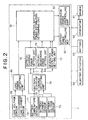
- Fig.2 is a block diagram illustrating the power controlling mechanism of the hybrid excavator 1.
- the block diagram shown in Fig.2 consists of the engine 61, a generator 62, a battery 63 to store surplus power generated by the generator 62 and to supply an electric actuator 64 with power appropriately, the electric actuator 64, and a power controlling mechanism 7, wherein the power supply from the battery 63 to the electric actuator 64 and that from the generator 62 to the electric actuator 64 or the battery 63 are made through DC (direct current) voltage lines.
- the electric actuator 64 represents either the integrated actuator Al for boom, the integrated actuator A2 for arm or the integrated actuator A3 for bucket etc., only one out of which being illustrated in Fig.2.
- the power controlling mechanism 7 shown in Fig.2 comprises a battery temperature sensor 71, a battery current sensor 72, a battery voltage sensor 73, a battery state-of-charge detecting unit 74, a battery-charging power setting unit 75, a battery-discharging power setting unit 76, a generator output power setting unit 77, a load voltage sensor 78, a load current sensor 79, a load power detecting unit 80, a generator / battery power distribution determining unit 81, a battery power controlling unit 82, and a generator power controlling unit 83.
- the battery temperature sensor 71 detects temperature of the battery 63 and outputs a battery temperature TEMP b as a detection result at the battery state-of-charge detecting unit 74, the battery-charging power setting unit 75, and the battery-discharging power setting unit 76.
- the battery current sensor 72 detects output current of the battery 63 and outputs an output current I b as a detection result at the battery state-of-charge detecting unit 74.
- the battery voltage sensor 73 also detects voltage between terminals of the battery 63 and outputs a voltage between terminals V b as a detection result at the battery state-of-charge detecting unit 74.
- the battery state-of-charge detecting unit 74 calculates power of the battery 63 using the output current I b of the battery 63 inputted from the battery current sensor 72 and the voltage V b between terminals of the battery 63 inputted from the battery voltage sensor 73, and then calculates charge quantity J of the battery 63 based on the calculated power.
- the battery state-of-charge detecting unit 74 then operates the following expression to calculate a ratio of charge quantity J to a maximum charge quantity J max of the battery 63, that is a state-of-charge SOC (%), and then outputs the SOC as a calculation result at the battery-charging power setting unit 75, the battery-discharging power setting unit 76, and the generator output power setting unit 77.
- SOC J J max ⁇ 100
- the SOC of the battery 63 is calculated correcting the voltage V b between terminals by the temperature TEMP b of the battery 63 detected at the battery temperature sensor 71 because the voltage V b detected at the battery voltage sensor 73 depends on temperature.
- charge quantity J of the battery 63 may be calculated accumulating voltages V b between terminals or output currents I b of the battery 63, instead of accumulating powers.
- the battery-charging power setting unit 75 determines maximum value of the charging power for the battery 63 using the temperature TEMP b of the battery 63 inputted from the battery temperature sensor 71 and the state-of-charge SOC of the battery 63 inputted from the battery state-of-charge SOC detecting unit 74, and outputs the maximum charging power P bc as a determination result at the generator / battery power distribution determining unit 81.
- the battery-charging power setting unit 75 takes predefined charging power setting value corresponding to the temperature TEMP b and the state-of-charge SOC out of the table. The battery-charging power setting unit 75 then determines the taken setting value as a maximum value of charging power (maximum charging power P bc ) of the battery 63 and outputs P bc at the generator / battery power distribution determining unit 81.
- the battery-discharging power setting unit 76 determines maximum value of the discharging power for the battery 63 using the temperature TEMP b of the battery 63 inputted from the battery temperature sensor 71 and the state-of-charge SOC of the battery 63 inputted from the battery state-of-charge SOC detecting unit 74, and outputs the maximum discharging power P bd as a determination result at the generator / battery power distribution determining unit 81.
- the battery-discharging power setting unit 76 takes predefined discharging power setting value corresponding to the temperature TEMP b and the state-of-charge SOC out of the table.
- the battery-discharging power setting unit 76 determines the taken setting value as a maximum value of discharging power (maximum discharging power P bd ) of the battery 63 and outputs P bd at the generator / battery power distribution determining unit 81.
- the generator output power setting unit 77 determines upper limit value (upper limit P gu of the generator output) and lower limit value (lower limit P gl of the generator output) of the output power of the generator 62 using the state-of-charge SOC of the battery 63 inputted from the battery state-of charge detecting unit 74, and outputs the upper limit P gu of the generator output and the lower limit P gl of the generator output as a determination result at the generator / battery power distribution determining unit 81.
- the generator output power setting unit 77 takes predefined upper limit value of the generator output corresponding to the state-of-charge SOC out of the table, and determines the taken upper limit value as an upper limit value of the output power of the generator 62 (upper limit P gu of the generator output).
- the generator output power setting unit 77 Based on the state-of-charge SOC of the battery 63, the generator output power setting unit 77 takes predefined lower limit value of the generator output corresponding to the state-of-charge SOC out of the table, and determines the taken lower limit value as a lower limit value of the output power of the generator 62 (lower limit P gl of the generator output). Then, the generator output power setting unit 77 outputs determined upper limit P gu of the generator output and lower limit P gl of the generator output at the generator / battery power distribution determining unit 81.
- the load voltage sensor 78 detects voltage at an input unit of the electric actuator 64, and outputs load voltage V L as a detection result at the load power detecting unit 80.
- the load current sensor 79 detects current at the input unit of the electric actuator 64, and outputs load current I L as a detection result at the load power detecting unit 80.
- the load power detecting unit 80 operates the following expression to detect required power P L for the electric actuator 64 using the load voltage V L inputted from the load voltage sensor 78 and the load current I L inputted from the load current sensor 79, and then outputs the P L as a detection result at the generator / battery power distribution determining unit 81.
- P L V L ⁇ I L
- the generator / battery power distribution determining unit 81 determines battery power P b and generator power P g based on the required power P L for the electric actuator 64 inputted from the load power detecting unit 80, the maximum charging power P bc inputted from the battery-charging power setting unit 75, the maximum discharging power P bd inputted from the battery-discharging power setting unit 76, the upper limit P gu of the generator output and the lower limit P gl of the generator output inputted from the generator output power setting unit 77.
- the generator / battery power distribution determining unit 81 then outputs a command signal including the battery power P b as a determination result at the battery power controlling unit 82 while outputs another command signal including the generator power P b as a determination result at the generator power controlling unit 83.
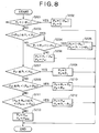
- the processing above will hereinafter be described in detail referring to the flowchart of Fig. 8.
- the battery power controlling unit 82 controls charge / discharge of the battery 63 to the battery power P b included in the command signal inputted from the generator / battery power distribution determining unit 81.
- the generator power controlling unit 83 also controls generation of the generator 62 to the generator power P g included in the command signal inputted from the generator / battery power distribution determining unit 81.
- Fig.7 is a flowchart showing a process of the power controlling method
- Fig.8 is a flowchart showing a process of the power distribution determining processing between the generator and the battery shown in the flowchart of Fig.7
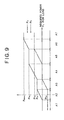
- Fig.9 is an illustration of the power distribution determining processing between the generator and the battery, wherein the solid line represents the generator power P g while the alternate long and short dash line the battery power P b .
- step S101 the battery state-of-charge detecting unit 74 calculates state-of-charge SOC of the battery 63 using the output current I b of the battery 63 inputted from the battery current sensor 72 and the voltage V b between terminals of the battery 63 inputted from the battery voltage sensor 73, with the voltage V b between terminals being corrected by the temperature TEMP b of the battery 63 inputted from the battery temperature sensor 71.
- the battery state-of-charge detecting unit 74 then outputs the state-of-charge SOC as a calculation result at the battery-charging power setting unit 75, the battery-discharging power setting unit 76, and the generator output power setting unit 77.
- step S102 the battery-charging power setting unit 75 determines maximum value of the charging power of the battery 63 using the temperature TEMP b of the battery 63 inputted from the battery temperature sensor 71 and the state-of-charge SOC of the battery 63 inputted from the battery state-of-charge detecting unit 74, and then outputs the maximum charging power P bc at the generator / battery power distribution determining unit 81.
- step S103 the battery-discharging power setting unit 76 determines maximum value of the discharging power of the battery 63 using the temperature TEMP b of the battery 63 inputted from the battery temperature sensor 71 and the state-of-charge SOC of the battery 63 inputted from the battery state-of-charge detecting unit 74, and then outputs the maximum discharging power P bd at the generator / battery power distribution determining unit 81.
- step S104 the generator output power setting unit 77 determines upper limit value (upper limit P gu of the generator output) and lower limit value (lower limit P gl of the generator output) of the output power of the generator 62 using the state-of-charge SOC of the battery 63 inputted from the battery state-of-charge detecting unit 74, and outputs the upper limit P gu of the generator output and the lower limit P gl of the generator output as a determination result at the generator / battery power distribution determining unit 81.
- upper limit value upper limit P gu of the generator output
- lower limit value lower limit P gl of the generator output
- step S105 the load power detecting unit 80 detects required power P L for the electric actuator 64 using the load voltage V L inputted from the load voltage sensor 78 and the load current I L inputted from the load current sensor 79, and then outputs the P L as a detection result at the generator / battery power distribution determining unit 81.
- step S106 the generator / battery power distribution determining unit 81 determines generator power P g and battery power P b , and then outputs a command signal including the generator power P g as a determination result at the generator power controlling unit 83 while outputs another command signal including the battery power P b as a determination result at the battery power controlling unit 83. That is, the generator / battery power distribution determining unit 81 executes a power distribution determining processing between the generator and the battery (refer to Fig.8).
- step S107 The battery power controlling unit 82 controls charge / discharge of the battery 63 to the battery power P b indicated by the command signal inputted from the generator / battery power distribution determining unit 81.
- the generator power controlling unit 83 controls generation of the generator 62 to the generator power P g indicated by the command signal inputted from the generator / battery power distribution determining unit 81.
- step S201 the generator / battery power distribution determining unit 81 judges whether or not the required power P L for the electric actuator 64 is smaller than the negative value of the maximum charging power P bc of the battery 63 (P L ⁇ - P bc ). In case the required power p L is smaller than the negative value of the maximum charging power p bc (step S201: YES), the process moves to step 202 while in case the required power P L is not smaller than the negative value of the maximum charging power P bc (step S201: NO), the process moves to step 203.
- step S202 the generator / battery power distribution determining unit 81 determines the battery power P b of the battery 63 and the generator power P b' of the generator 62 as "- P b " and "0" respectively, and then finishes the power distribution determining processing. That is, the battery 63 will be charged by the maximum charging power P bc .
- step S203 the generator / battery power distribution determining unit 81 judges whether or not the required power P L for the electric actuator 64 is within the range of being bigger than the negative value of the maximum charging power P bc of the battery 63 and smaller than the lower limit P gl of the generator power (-P bc ⁇ P L ⁇ P gl ).
- step S203: YES the process moves to step S204 while in case the required power P L is not within the range (step S203: NO), to step S207.
- step S204 the generator / battery power distribution determining unit 81 judges whether or not the negative value of the maximum charging power P bc of the battery 63 is bigger than the value gotten by subtracting the lower limit P gl of the generator power from the required power P L for the electric actuator 64 (P L - P gl ⁇ P bc ).
- step S204: YES the process moves to step S205 while in case the negative value of the maximum charging power P bc of the battery 63 is not bigger than the other value (step S204: NO), to step S206.
- step S205 the generator / battery power distribution determining unit 81 determines the battery power P b of the battery 63 and the generator power P g of the generator 62 as "- P bc " " and "P L - (- P bc )" respectively (section A2 in Fig.9), and then finishes the power distribution determining processing. That is, the battery 63 will be charged by the maximum charging power P bc , slack of power required to charge the battery by the maximum charging power P bc being taken up with the generator 62.
- the reason the generator power P g of the generator 62 falls below the lower limit P gl of the power of the generator 62 is that the generator 62 should work under the lower limit P gl of the generator power to prevent the battery 63 from being charged by power over the maximum charging power P bc of the battery 63 which may occurs in case the power P g of the generator 62 is arranged to the lower limit P gl of the generator power.
- step S206 the generator / battery power distribution determining unit 81 determines the battery power P b of the battery 63 and the generator power P g of the generator 62 as "P L - P gl " and "P gl “ respectively (section A3 in Fig.9), and then finishes the power distribution determining processing. That is, the generator power P g of the generator 62 will be controlled to the lower limit P gl of the power of the generator 62, surplus of the power generated by the generator 62 charging the battery 63.
- step S207 the generator / battery power distribution determining unit 81 judges whether or not the required power P L for the electric actuator 64 is within the range of bigger than the lower limit P gl of the generator power and being the upper limit P gu of the generator power or less (P gl ⁇ P L ⁇ P gu ). In case the required power P L is within the range (step S207: YES), the process moves to step S208 while in case the required power P L is not within the range (step S207: NO), to step S209.
- step S208 the generator / battery power distribution determining unit 81 determines the battery power P b of the battery 63 and the generator power P g of the generator 62 as "0" and "P L " respectively (section A4 in Fig 9), and then finishes the power distribution determining processing. That is, the generator power P g of the generator 62 will be within the range of the lower limit P gl of the generator power or more and being smaller than the upper limit P gu of the generator power, the battery 63 neither charging nor discharging.
- step S209 the generator / battery power distribution determining unit 81 judges whether or not the required power P L for the electric actuator 64 is within the range of being bigger than the upper limit P gu of the generator power and being the value or more gotten by adding the maximum discharging power P bd of the battery 63 to the upper limit P gu of the generator power (P gu ⁇ P L ⁇ P gu + P bd ).
- the process moves to step S210 while in case the required power P L is not within the range (step S209: NO), to step S211.
- step S210 the generator / battery power distribution determining unit 81 determines the battery power P b of the battery 63 and the generator power P g of the generator 62 as "P L - P gu " and "P gu " respectively (section A5 in Fig.9), and then finishes the power distribution determining processing. That is, the power P g generated by the generator 62 will be limited to the upper limit P gu of the generator power, and slack of generation power "P L - P gu " by the generator 62 will be taken up with the battery 63. Moreover, the discharging power of the battery 63 is the maximum discharging power P bd or less.
- step S211 the generator / battery power distribution determining unit 81 judges whether or not the required power P L for the electric actuator 64 is within the range of being the value gotten by adding the maximum discharging power P bd of the battery 63 to the upper limit P gu of the generator power and being smaller than the value or more gotten by adding the maximum discharging power P bd of the battery 63 to a maximum generator power P gmax (P gu +P bd ⁇ P L ⁇ P gmax + P bd ).
- the process moves to step S212 while in case the required power P L is not within the range (step S211: NO), to step S213.
- the maximum generator power P gmax is the maximum value of the output power of the generator 62 depending on the performance of the engine 61 and the generator 62.
- step S212 the generator / battery power distribution determining unit 81 determines the battery power P b of the battery 63 and the generator power P g of the generator 62 as "P bd " and "P L - P bd " respectively (section A6 in Fig.9), and then finishes the power distribution determining processing. That is, the battery 63 is controlled to discharge at the maximum discharging power P bd , while the generator 62 is controlled to generate power of "P L - P bd ".
- the generator 62 works to generate power over the upper limit P gu of the generator power so as to supply the electric actuator 64 with the required power P L for the electric actuator 64 from the generator 62 and the battery 63.
- the generator / battery power distribution determining unit 81 determines the battery power P b of the battery 63 and the generator power P g of the generator 62 as "P bd " and "P gmax " respectively (section A7 in Fig.9), and then finishes the power distribution determining processing. That is, the battery 63 is controlled to discharge at the maximum discharging power P bd , while the generator 62 is controlled to generate power of the maximum generator power P gmax . In this case, all of the required power P L for the electric actuator 64 is not supplied for the electric actuator 64.
- the battery 63 is controlled to discharge at the maximum discharging power P bd or less e.g. not exceeding its discharging capacity, and also to charge at the maximum charging power P bc or less e.g. not exceeding its charging capacity, so it is possible to prevent performance deterioration of the battery 63 due to charging / discharging over the battery capacity.
- the output power of the generator 62 is controlled to being within the range between the lower limit P gl of the generator power and the upper limit P gu of the generator power, efficiencies of the engine 61 and the generator 62 being favorable therebetween (except for section A2, A6 and A7 in Fig. 9), so the fuel consumption of the engine 61 is improved.
- the maximum charging power P bc and the maximum discharging power P bd of the battery 63 are set according to its state-of charge even though the charging / discharging capacity of the battery 63 varies depending on its state-of-charge.
- a power controller for hybrid excavator according to a second embodiment of the present invention will be described below referring to the accompanying drawings.
- the hybrid excavator 1 in the first embodiment described using Fig.1 is available as a hybrid excavator to which a power controller according to the second embodiment is applied.
- Fig. 10 is a block diagram illustrating a power controlling mechanism according to the second embodiment. Elements substantially equal to those in the first embodiment are provided with the same symbols.
- the block diagram shown in Fig. 10 consists of an engine 61, a generator 62, a battery 63, an electric actuator 64, and a power controlling mechanism 9. Power supply from the battery 63 to the electric actuator 64 and that from the generator 62 to the electric actuator 64 or the battery 63 are made through DC voltage lines.
- the electric actuator 64 represents either an integrated actuator A1 for boom, an integrated actuator A2 for arm or a integrated actuator A3 for bucket etc., only one out of which being illustrated in Fig. 10.
- the power controlling mechanism 9 shown in Fig. 10 comprises a battery temperature sensor 71, a battery current sensor 72, a battery voltage sensor 73, a battery state-of-charge detecting unit 74, a battery power-loss characteristics determining unit 91, a generator output power-loss characteristics determining unit 92, a load voltage sensor 78, a load current sensor 79, a load power detecting unit 80, a generator / battery power distribution determining unit 93, a battery power controlling unit 82, and a generator power controlling unit 83.
- Processing details of the battery temperature sensor 71, the battery current sensor 72, the battery voltage sensor 73, the battery state-of-charge detecting unit 74, the load voltage sensor 78, the load current sensor 79, the load power detecting unit 80, the battery power controlling unit 82, and the generator power controlling unit 83 are substantially equal to those described in the first embodiment.
- the battery power-loss characteristics determining unit 91 determines loss characteristics of the battery 63 against input power to the battery 63 using the temperature TEMP b of the battery 63 inputted from the battery temperature sensor 71 and the state-of-charge SOC of the battery 63 inputted from the battery state-of-charge detecting unit 74, and then outputs coefficients (a, b, c) of quadratic expression in an approximation of the determined characteristics by a quadratic expression at the generator / battery power distribution determining unit 93.
- (a, b, c) (0.0025, 0.2032, 0).
- P ⁇ 2 bross a ⁇ P ⁇ 2 b 2 + b ⁇ P ⁇ 2 b + c
- the battery power-loss characteristics determining unit 91 Based on the temperature TEMP b and state-of-charge SOC of the battery 63, the battery power-loss characteristics determining unit 91 then takes coefficients (a, b, c) corresponding to the temperature TEMP b and the state-of-charge SOC out of the table. The battery power-loss characteristics determining unit 91 outputs the taken coefficients (a, b, c) at the generator / battery power distribution determining unit 93.
- the generator / battery power distribution determining unit 93 determines input power P2 b of the battery 63 and output power P2 g of the generator 62.
- the generator / battery power distribution determining unit 93 outputs a command signal including the input power P2 b of the battery 63 as a determination result at the battery power controlling unit 82 while outputs a command signal including the output power P2 g of the generator 62 at the generator power controlling unit 83.
- Fig. 14 is a diagram illustrating the power distribution determining method.
- power consumption P2 gns represents the power consumed by the engine 61 while power loss P2 gross the power the engine 61 and the generator 62 lose, output power P2 g the power the generator 62 outputs, input power P2 b the power input to the battery 63, power loss P2 bross the power the battery 63 lose, and power consumption P2 L the power consumed by the electric actuator 64.
- an available charging power P2 bavl of the battery 63 which is available for driving the electric actuator 64 out of the input power P2 b of the battery 63, is represented with the following expression (2).
- P ⁇ 2 bavl P ⁇ 2 b - P ⁇ 2 bross
- efficiency ⁇ of the entire system shown in Fig. 14 is represented with the following expression (3).
- output power P2 g of the generator 62, input power P2 b of the battery 63, and power consumption P2 L of the electric actuator 64 satisfy the following relationship represented with the expression (6).
- P ⁇ 2 b P ⁇ 2 g - P ⁇ 2 L
- the following expression (7) is obtained by transforming the foregoing expression (3) using the foregoing expression (4), (5), and (6).
- ⁇ - a ⁇ P ⁇ 2 g 2 + 1 - b + 2 ⁇ a ⁇ P ⁇ 2 L ⁇ P ⁇ 2 g + b ⁇ P ⁇ 2 L - c - a ⁇ P ⁇ 2 g 2 ⁇ ⁇ P ⁇ 2 g 2 + 1 + ⁇ ⁇ P ⁇ 2 g + ⁇
- output power P2 g of the generator 62 is calculated substituting the power consumption (required power) P2 L of the electric actuator 64 detected by the load power detecting unit 80 for the foregoing expression (10). Furthermore, input power P2 b of the battery 62 is calculated substituting the power consumption P2 L of the electric actuator 64 and the output power P2 g for the foregoing expression (6).
- Efficiency ⁇ of the entire system is best improved and fuel consumption of the engine is also improved by controlling generation and charge by the generator 62 and the battery 63 respectively to the output power P2 g of the generator and the input power P2 b of the battery as calculated above.
- Fig. 15 is a flowchart showing a process of the power controlling method by the power controlling mechanism shown in Fig. 10.
- step S301 the battery state-of-charge detecting unit 74 calculates state-of-charge SOC of the battery 63 using the output current I b of the battery 63 inputted from the battery current sensor 72 and the voltage V b between terminals of the battery 63 inputted from the battery voltage sensor 73, with the voltage V b between terminals being corrected by the temperature TEMP b of the battery 63 inputted from the battery temperature sensor 71, and then outputs the state-of-charge SOC as a calculation result at the battery power-loss characteristics determining unit 91.
- the battery power-loss characteristics determining unit 91 determines coefficients (a, b, c) of quadratic expression in an approximation of loss characteristics of the battery 63 using the temperature TEMP b of the battery 63 inputted from the battery temperature sensor 71 and the state-of-charge SOC of the battery 63 inputted from the battery state-of-charge detecting unit 74, and then outputs the coefficients (a, b, c) as a determination result at the generator / battery power distribution determining unit 93.
- step S303 the generator output power-loss characteristics determining unit 92 determines coefficients ( ⁇ , ⁇ , ⁇ ) of quadratic expression in an approximation of loss characteristics of the engine 61 and the generator 62, and then outputs the coefficients ( ⁇ , ⁇ , ⁇ ) as a determination result at the generator / battery power distribution determining unit 93.
- step S304 the load power detecting unit 80 detects required power P2 L for the electric actuator 64 based on the load voltage inputted from the load voltage sensor 78 and the load current inputted from the load current sensor 79, and then outputs the required power P2 L at the generator / battery power distribution determining unit 93.
- step S305 the generator / battery power distribution determining unit 93 calculates output power P2 g of the generator by operating the foregoing expression (10) using the required power P2 L for the electric actuator 64, the coefficients (a, b, c) inputted from the battery power-loss characteristics determining unit 91, and the coefficients ( ⁇ , ⁇ , ⁇ ) inputted from the generator output power-loss characteristics determining unit 92. Then, the generator / battery power distribution determining unit 93 outputs a command signal including the calculated output power P2 g at the generator power controlling unit 83.
- the generator / battery power distribution determining unit 93 calculates input power P2 b of the battery 63 by operating the foregoing expression (6) using the required power P2 L for the electric actuator 64 and the calculated output power P2 g of the generator 62, and then outputs another command signal including the calculated input power P2 b at the battery power controlling unit 82.
- step S306 the battery power controlling unit 82 controls charge of the battery 63 to the input power P2 b indicated by the command signal input from the generator / battery power distribution determining unit 93.
- the generator power controlling unit 83 controls generation of the generator 62 to the input power P2 g indicated by the command signal inputted from the generator / battery power distribution determining unit 93.
- total energy loss of the hybrid construction machine is reduced and then fuel consumption of the engine is improved, wherein the output power of the generator 62 and the input power of the battery 61 are determined taking into consideration loss characteristics of the generator 62 and the engine 61 against output of the generator 62, and loss characteristics of the battery 61 against input power.
- the power controller described above is applicable to a hybrid construction machine such as a hybrid excavator and the like including a generator and an electrical energy storage unit.
Landscapes
- Engineering & Computer Science (AREA)
- Power Engineering (AREA)
- Transportation (AREA)
- Mechanical Engineering (AREA)
- Combustion & Propulsion (AREA)
- Chemical & Material Sciences (AREA)
- Sustainable Energy (AREA)
- Sustainable Development (AREA)
- Life Sciences & Earth Sciences (AREA)
- Civil Engineering (AREA)
- Structural Engineering (AREA)
- General Engineering & Computer Science (AREA)
- Mining & Mineral Resources (AREA)
- Automation & Control Theory (AREA)
- Charge And Discharge Circuits For Batteries Or The Like (AREA)
- Operation Control Of Excavators (AREA)
- Electric Propulsion And Braking For Vehicles (AREA)
- Control Of Charge By Means Of Generators (AREA)
- Supply And Distribution Of Alternating Current (AREA)
- Hybrid Electric Vehicles (AREA)
- Control Of Eletrric Generators (AREA)
Abstract
Description
- The present invention relates to a power controller for controlling output power of generator and charging / discharging power of electrical energy storage unit, both installed in hybrid construction machine.
- Engine for self-traveling has been installed in construction machine such as hydraulic excavators and the like, the engine operating as a power source to drive hydraulic pump and supply each hydraulic actuator such as rotating actuators, boom cylinders, arm cylinders etc. with hydraulic oil discharged from the hydraulic pump, to drive each portion. However, known construction machine using engine as power source suffer from problems in that they burn too much gas due to large load fluctuation and inordinate burden to the engine, and that they generate noise and / or exhaust gas emissions. Accordingly hybrid construction machine containing motors driven by combination of generator and electrical energy storage unit (battery) have been developed to overcome the foregoing deficiencies. As examples of the hybrid construction machine, there have been provided a series system one disclosed in
Japanese Patent Laid-Open Publication No. 2000-283107 Japanese Patent Laid-Open Publication No. Hei 10-42587 Laid-Open Publication No.2000-226183 - Generally in either system of the hybrid construction machine above, voltage between battery terminals has been measured and the battery state-of-charge SOC has been calculated based on the measurement results. Then, generator has been operated when the state-of-charge SOC become a specified value or less, while the generator has been halted, or the output of the generator has been reduced when the state-of-charge SOC become the specified value or more. With such control, the state-of-charge SOC of the battery has been kept within a specified range.
- However, the foregoing state-of-charge SOC based control have suffered from the problem in that halting generator, or reducing the output of the generator caused drop of efficiencies of engine and generator in case of small load and high state-of-charge SOC. In addition, the foregoing state-of-charge SOC based control in the same case above have also suffer from the problem in that there might be a situation that electric actuators might not be supplied with electric power required for its operation because of time-lag to restart engine once halted, and it was required to increase battery capacity to overcome the problem. Therefore, it was difficult to achieve the conditions simultaneously of supplying appropriate electric power required for electric actuator, controlling battery state-of-charge, operating engine and generator highly efficiently. For example, if it was prioritized to operate engine and generator highly efficiently, battery capacity was resulted in increase in case of small load of electric actuator, and therefore it was difficult to control battery state-of-charge SOC within a specified range. In contrast, if it was prioritized to control battery state-of-charge SOC within a specified range, output power fluctuation due to load fluctuation of engine and generator was resulted in increase, and therefore efficiencies of engine and generator drop.
- In addition, charging / discharging over battery capacity in case of low battery temperature would have been likely to cause the performance deterioration of the battery because of battery characteristics that charging / discharging capacity depend on its temperature. Further, controlling only based on battery state-of-charge SOC would have been likely to cause the increase of loss because losses of battery and generator vary with output powers of generator and battery respectively while internal loss of battery varies with input power of the battery.
- Accordingly, an object of the present invention is to provide a power controller for hybrid construction machine which makes it possible to prevent performance deterioration of its battery due to charging / discharging over the battery capacity as well as to improve fuel consumption of its engine. It is another object of the present invention to provide a power controller for hybrid construction machine, which makes it possible to improve fuel consumption of its engine.
- A power controller for hybrid construction machine of the present invention, including an engine, a generator which is driven by the engine, an electrical energy storage unit to store electric power generated by the generator, and one or more electric actuators driven by the generator and the electrical energy storage unit, is characterized by comprising a load power detecting means to detect required power for the one or more electric actuators; a charging power setting means to set maximum value of charging power of the electrical energy storage unit; a discharging power setting means to set maximum value of discharging power of the electrical energy storage unit; a generator output power setting means to set upper limit and lower limit value of the output power of the generator; a power distribution determining means to determine power distribution between the generator and the electrical energy storage unit based on the set value by the charging power setting means, the set value by the discharging power setting means, the set value by the generator output power setting means, and the required power as the detection result by the load power detecting means; a generator power controlling means to control output power of the generator based on the determined power distribution as the determination result by the power distribution determining means; and a power controlling means for electrical energy storage unit to control charging / discharging power of the electrical energy storage unit based on the determination result by the power distribution determining means.
- The power controller for hybrid construction machine above makes it possible to improve fuel consumption of the engine as well as to prevent performance deterioration of the electrical energy storage unit if upper limit and lower limit value of the generator are set within a range to operate the engine and the generator highly efficiently, and maximum value of charging / discharging power for the electrical energy storage unit is set so that the electrical energy storage unit is not charged / discharged over its capacity.
- The power controller for hybrid construction machine mentioned above is characterized by further comprising a state-of-charge detecting means to detect state-of-charge of the electrical energy storage unit, wherein the generator output power setting means sets upper limit and lower limit value of the output power of the generator based on the detected state-of-charge as the detection result by the state-of-charge detecting means. This power controller makes it possible to control output power of the generator and charging / discharging power of the electrical energy storage unit according to the state-of-charge of the electrical energy storage unit, wherein the upper limit and the lower limit value of output power of the generator are set according to the state-of-charge of the electrical energy storage unit.
- The power controller for hybrid construction machine mentioned above is characterized by further comprising a state-of-charge detecting means to detect state-of-charge of the electrical energy storage unit, wherein the charging power setting means sets maximum value of the charging power of the electrical energy storage unit based on the detection result by the state-of-charge detecting means, and the discharging power setting means sets maximum value of the discharging power of the electrical energy storage unit based on the detection result by the state-of-charge detecting means. This power controller makes it possible to prevent performance deterioration of the electrical energy storage unit due to charging / discharging over its capacity as a result of prevention of charging / discharging over the capacity regardless of the state-of-charge of the electrical energy storage unit, wherein maximum values of the charging power and the discharging power of the electrical energy storage unit are set according to its state-of-charge even though the charging / discharging capacity of the electrical energy storage unit varies depending on its state-of-charge.
- The power controller for hybrid construction machine mentioned above is characterized by further comprising a temperature detecting means to detect temperature of the electrical energy storage unit, wherein the charging power setting means sets maximum value of the charging power of the electrical energy storage unit based on the detected temperature as the detection result by the temperature detecting means, and the discharging power setting means sets maximum value of the discharging power of the electrical energy storage unit based on the detection result by the temperature detecting means. This power controller makes it possible to prevent performance deterioration of the electrical energy storage unit due to charging / discharging over its capacity as a result of prevention of charging / discharging over the capacity regardless of the temperature of the electrical energy storage unit, wherein maximum values of the charging power and the discharging power of the electrical energy storage unit are set according to its temperature even though the charging / discharging capacity of the electrical energy storage unit varies depending on its temperature.
- Another power controller for hybrid construction machine of the present invention, including an engine, a generator which is driven by the engine, an electrical energy storage unit to store electric power generated by the generator, and one or more electric actuators driven by the generator and the electrical energy storage unit, is characterized by comprising a load power detecting means to detect required power for the one or more electric actuators; a power distribution determining means to determine power distribution between the generator and the electrical energy storage unit to maximize power consumption efficiency by the engine, utilizing the required power detected by the load power detecting means, the loss characteristics of the generator and the engine against an output power of the generator, and the loss characteristics of the electrical energy storage unit against an input power of the electrical energy storage unit; a generator power controlling means to control output power of the generator based on the determined power distribution as the determination result by the power distribution determining means; and a power controlling means for electrical energy storage unit to control input power of the electrical energy storage unit based on the determination result by the power distribution determining means.
- The power controller for hybrid construction machine mentioned above makes it possible to improve fuel consumption of the engine caused by reducing total energy loss of the hybrid construction machine, wherein output power of the generator and charging / discharging power of the electrical energy storage unit are determined taking into consideration the loss characteristics of the generator and the engine against the output power of the generator, and the loss characteristics of the electrical energy storage unit against the input power of the electrical energy storage unit.
- The power controller for hybrid construction machine mentioned above is characterized by further comprising a temperature detecting means to detect temperature of the electrical energy storage unit; and a power loss characteristics determining means for electrical energy storage unit to determine the loss characteristics of the electrical energy storage unit against the input power of the electrical energy storage unit based on the detection result by the temperature detecting unit. This power controller makes it possible to improve fuel consumption of the engine caused by reducing energy loss regardless of the temperature of the electrical energy storage unit, wherein the loss characteristics above is determined according to the temperature of the electrical energy storage unit.
- The power controller for hybrid construction machine mentioned above is characterized by further comprising a state-of-charge detecting means to detect state-of-charge of the electrical energy storage unit; and a power loss characteristics determining means for electrical energy storage unit to determine the loss characteristics of the electrical energy storage unit against the input power of the electrical energy storage unit based on the detection result by the state-of-charge detecting unit. This power controller makes it possible to improve fuel consumption of the engine caused by reducing energy loss regardless of the state-of-charge of the electrical energy storage unit, wherein the loss characteristics above is determined according to the state-of-charge of the electrical energy storage unit.
-
- Fig. 1 is a view showing a frame format of an outline configuration of a hybrid excavator to which a power controlling mechanism of a first embodiment of the present invention is applied.
- Fig.2 is a block diagram illustrating the power controlling mechanism of the hybrid excavator shown in Fig. 1.
- Fig. 3 is a graph showing charging power characteristics of a battery installed in the hybrid excavator shown in Fig. 1 against its state-of-charge SOC.
- Fig.4 is a graph showing discharging power characteristics of a battery installed in the hybrid excavator shown in Fig.1 against its state-of-charge SOC.
- Fig. 5 is a graph showing upper limit characteristics of a generator output against the state-of-charge SOC of the battery installed in the hybrid excavator shown in Fig.1.
- Fig.6 is a graph showing lower limit characteristics of a generator output against the state-of-charge SOC of the battery installed in the hybrid excavator shown in Fig. 1.
- Fig. 7 is a flowchart showing a process of the power controlling method by the power controlling mechanism shown in Fig. 2.
- Fig.8 is a flowchart showing a process of the power distribution determining processing between the generator and the battery shown in the flowchart of Fig.7.
- Fig.9 is an additional illustration of the power distribution determining processing shown in the flowchart of Fig.8.
- Fig.10 is a block diagram illustrating another power controlling mechanism of a hybrid excavator according to a second embodiment of the present invention.
- Fig.11 is a graph showing power loss characteristics of the battery installed in the hybrid excavator shown in Fig.1 against its input power.
- Fig.12 is a graph showing power loss characteristics of the battery installed in the hybrid excavator shown in Fig.1 against its input power.
- Fig.13 is a graph showing power loss characteristics of the generator and the battery installed in the hybrid excavator shown in Fig.1 against the output power of the generator.
- Fig.14 is a diagram illustrating the power distribution determining method by the power controlling mechanism shown in Fig. 10.
- Fig. 15 is a flowchart showing a process of the power controlling method by the power controlling mechanism shown in Fig. 10.
- The present invention will be more fully understood from the following description of preferred embodiments when reference is made to the accompanying drawings. Though a series system hybrid excavator is described below as an example of a hybrid construction machine, the present invention is also applicable for various types of hybrid construction machine such as parallel system ones etc.
- A power controller for hybrid excavator according to a first embodiment of the present invention will be described below referring to the accompanying drawings.
- At first, a hybrid excavator to which a power controller according to the first embodiment is applied will be described referring to Fig 1. It should be noted that Fig.1 is a view showing a frame format of an outline configuration of a hybrid excavator.
- In Fig.1, a
hybrid excavator 1 comprises a lowertraveling body 2, an upper rotatingbody 3 which is connected rotatably to the center portion of the upper surface of thelower traveling body 2, and anexcavating attachment 4 which is connected to the front portion of the upper rotatingbody 3. - The lower traveling
body 2 includes a pair of crawler frames 21 arranged at the both ends in parallel, acrawler 22 configured rotatably around each crawler frame 21 to contact on the ground surface planarly, a motion reducer 23 and a motor 24 to drive in rotation thecrawler 22. The lowertraveling body 2 composed as described above drives in forward and reverse, revolves, rotates theentire hybrid excavator 1, driving in rotation eachcrawler 22 forward and backward respectively through the motion reducer 23 by the motor 24. - A
pivot 5 as rotating axis is configured orthogonal to the lower travelingbody 2 at the center portion of the upper surface of the lower travelingbody 2. The rotatingframe 31 that forms part of the upper rotatingbody 3 is connected to the upper portion of thepivot 5 pivotally. At the upper surface of the rotatingframe 31, there is configured acabin 32 for operator's cockpit and amachine housing 34 covered with aprotective cover 33 as well as one end of aboom 41 and aboom cylinder 42 of theexcavating attachment 4 axially up and down. - In the
machine housing 34, there is a rotatingmotor 35 and a rotating motion reducer 36 as well as an integrated actuator Al for boom comprising aboom motor 37 and aboom pump 38 in an integrated manner. Therotating motor 35 drives in rotating motion the rotatingframe 31 through therotating motion reducer 36 with thepivot 5 being a guided center. The integrated actuator A1 is connected to theboom cylinder 42 through an unillustrated hydraulic pipe, and drives the end side of theboom 41 up and down. - At the end of the
boom 41, anarm 43 is connected pivotally. At the end of thearm 43, abucket 44 is connected pivotally. In addition, theboom 41 and thearm 43 are connected to each other through anarm cylinder 45, while thearm 43 and thebucket 44 are connected to each other through abucket cylinder 46. For thesecylinders arm motor 47a and anarm pump 47b in an integrated manner while the integrated actuator A3 comprises abucket motor 48a and abucket pump 48b in an integrated manner. Each actuator A2, A3 moves forward and backward each cylinder rod of thecylinder arm 43 and thebucket 44 respectively axially up and down. - In the
machine housing 34, there are installed anengine 61, agenerator 62 to generate AC power according to speed (engine power) of theengine 61, as well as a battery 63 (an electrical energy storage unit) etc. - Next, a power controlling mechanism of the
hybrid excavator 1 having the configuration above will be described referring to Fig. 2. It should be noted that Fig.2 is a block diagram illustrating the power controlling mechanism of thehybrid excavator 1. - The block diagram shown in Fig.2 consists of the
engine 61, agenerator 62, abattery 63 to store surplus power generated by thegenerator 62 and to supply anelectric actuator 64 with power appropriately, theelectric actuator 64, and apower controlling mechanism 7, wherein the power supply from thebattery 63 to theelectric actuator 64 and that from thegenerator 62 to theelectric actuator 64 or thebattery 63 are made through DC (direct current) voltage lines. Theelectric actuator 64 represents either the integrated actuator Al for boom, the integrated actuator A2 for arm or the integrated actuator A3 for bucket etc., only one out of which being illustrated in Fig.2. - The
power controlling mechanism 7 shown in Fig.2 comprises abattery temperature sensor 71, abattery current sensor 72, abattery voltage sensor 73, a battery state-of-charge detecting unit 74, a battery-chargingpower setting unit 75, a battery-dischargingpower setting unit 76, a generator outputpower setting unit 77, aload voltage sensor 78, a loadcurrent sensor 79, a loadpower detecting unit 80, a generator / battery powerdistribution determining unit 81, a batterypower controlling unit 82, and a generatorpower controlling unit 83. - The
battery temperature sensor 71 detects temperature of thebattery 63 and outputs a battery temperature TEMPb as a detection result at the battery state-of-charge detecting unit 74, the battery-chargingpower setting unit 75, and the battery-dischargingpower setting unit 76. Thebattery current sensor 72 detects output current of thebattery 63 and outputs an output current Ib as a detection result at the battery state-of-charge detecting unit 74. Thebattery voltage sensor 73 also detects voltage between terminals of thebattery 63 and outputs a voltage between terminals Vb as a detection result at the battery state-of-charge detecting unit 74. - The battery state-of-
charge detecting unit 74 calculates power of thebattery 63 using the output current Ib of thebattery 63 inputted from thebattery current sensor 72 and the voltage Vb between terminals of thebattery 63 inputted from thebattery voltage sensor 73, and then calculates charge quantity J of thebattery 63 based on the calculated power. The battery state-of-charge detecting unit 74 then operates the following expression to calculate a ratio of charge quantity J to a maximum charge quantity Jmax of thebattery 63, that is a state-of-charge SOC (%), and then outputs the SOC as a calculation result at the battery-chargingpower setting unit 75, the battery-dischargingpower setting unit 76, and the generator outputpower setting unit 77.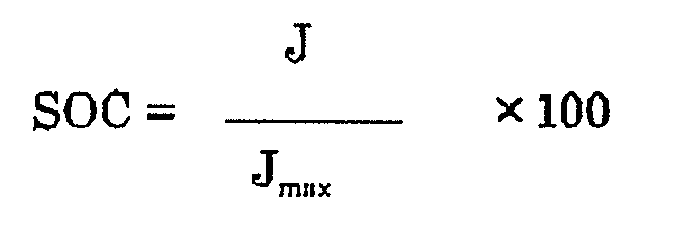
- It should be noted that the SOC of the
battery 63 is calculated correcting the voltage Vb between terminals by the temperature TEMPb of thebattery 63 detected at thebattery temperature sensor 71 because the voltage Vb detected at thebattery voltage sensor 73 depends on temperature. - In addition to above, charge quantity J of the
battery 63 may be calculated accumulating voltages Vb between terminals or output currents Ib of thebattery 63, instead of accumulating powers. - The battery-charging
power setting unit 75 determines maximum value of the charging power for thebattery 63 using the temperature TEMPb of thebattery 63 inputted from thebattery temperature sensor 71 and the state-of-charge SOC of thebattery 63 inputted from the battery state-of-chargeSOC detecting unit 74, and outputs the maximum charging power Pbc as a determination result at the generator / battery powerdistribution determining unit 81. - For details, there are stored predefined values of charging power of the
battery 63 against state-of-charge and temperature of thebattery 63 in a table (a memory unit) of the battery-chargingpower setting unit 75 as shown in Fig.3. In addition, values of charging power above are set not to exceed the charging capacity of thebattery 63. Based on the temperature TEMPb and the state-of-charge SOC of thebattery 63, the battery-chargingpower setting unit 75 takes predefined charging power setting value corresponding to the temperature TEMPb and the state-of-charge SOC out of the table. The battery-chargingpower setting unit 75 then determines the taken setting value as a maximum value of charging power (maximum charging power Pbc) of thebattery 63 and outputs Pbc at the generator / battery powerdistribution determining unit 81. - The battery-discharging
power setting unit 76 determines maximum value of the discharging power for thebattery 63 using the temperature TEMPb of thebattery 63 inputted from thebattery temperature sensor 71 and the state-of-charge SOC of thebattery 63 inputted from the battery state-of-chargeSOC detecting unit 74, and outputs the maximum discharging power Pbd as a determination result at the generator / battery powerdistribution determining unit 81. - For details, there are stored predefined values of discharging power of the
battery 63 against state-of-charge and temperature of thebattery 63 in a table (a memory unit) of the battery-dischargingpower setting unit 76 as shown in Fig.4. In addition, values of discharging power above are set not to exceed the discharging capacity of thebattery 63. Based on the temperature TEMPb and the state-of-charge SOC of thebattery 63, the battery-dischargingpower setting unit 76 takes predefined discharging power setting value corresponding to the temperature TEMPb and the state-of-charge SOC out of the table. The battery-dischargingpower setting unit 76 then determines the taken setting value as a maximum value of discharging power (maximum discharging power Pbd) of thebattery 63 and outputs Pbd at the generator / battery powerdistribution determining unit 81. - The generator output
power setting unit 77 determines upper limit value (upper limit Pgu of the generator output) and lower limit value (lower limit Pgl of the generator output) of the output power of thegenerator 62 using the state-of-charge SOC of thebattery 63 inputted from the battery state-ofcharge detecting unit 74, and outputs the upper limit Pgu of the generator output and the lower limit Pgl of the generator output as a determination result at the generator / battery powerdistribution determining unit 81. - For details, there are stored predefined upper limit values of the generator output against state-of-charge of the
battery 63 and predefined lower limit values of the generator output against state-of-charge of thebattery 63 in a table (a memory unit) of the generator outputpower setting unit 77 as shown in Fig. 5 and Fig.6 respectively. In addition, upper limit values and lower limit values above are set to make efficiencies of theengine 61 and thegenerator 62 favorable. Based on the state-of-charge SOC of thebattery 63, the generator outputpower setting unit 77 takes predefined upper limit value of the generator output corresponding to the state-of-charge SOC out of the table, and determines the taken upper limit value as an upper limit value of the output power of the generator 62 (upper limit Pgu of the generator output). Further, Based on the state-of-charge SOC of thebattery 63, the generator outputpower setting unit 77 takes predefined lower limit value of the generator output corresponding to the state-of-charge SOC out of the table, and determines the taken lower limit value as a lower limit value of the output power of the generator 62 (lower limit Pgl of the generator output). Then, the generator outputpower setting unit 77 outputs determined upper limit Pgu of the generator output and lower limit Pgl of the generator output at the generator / battery powerdistribution determining unit 81. - The
load voltage sensor 78 detects voltage at an input unit of theelectric actuator 64, and outputs load voltage VL as a detection result at the loadpower detecting unit 80. The loadcurrent sensor 79 detects current at the input unit of theelectric actuator 64, and outputs load current IL as a detection result at the loadpower detecting unit 80. - The load
power detecting unit 80 operates the following expression to detect required power PL for theelectric actuator 64 using the load voltage VL inputted from theload voltage sensor 78 and the load current IL inputted from the loadcurrent sensor 79, and then outputs the PL as a detection result at the generator / battery powerdistribution determining unit 81.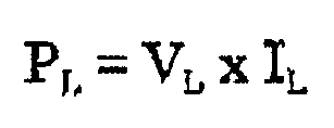
- The generator / battery power
distribution determining unit 81 determines battery power Pb and generator power Pg based on the required power PL for theelectric actuator 64 inputted from the loadpower detecting unit 80, the maximum charging power Pbc inputted from the battery-chargingpower setting unit 75, the maximum discharging power Pbd inputted from the battery-dischargingpower setting unit 76, the upper limit Pgu of the generator output and the lower limit Pgl of the generator output inputted from the generator outputpower setting unit 77. The generator / battery powerdistribution determining unit 81 then outputs a command signal including the battery power Pb as a determination result at the batterypower controlling unit 82 while outputs another command signal including the generator power Pb as a determination result at the generatorpower controlling unit 83. The processing above will hereinafter be described in detail referring to the flowchart of Fig. 8. - The battery
power controlling unit 82 controls charge / discharge of thebattery 63 to the battery power Pb included in the command signal inputted from the generator / battery powerdistribution determining unit 81. The generatorpower controlling unit 83 also controls generation of thegenerator 62 to the generator power Pg included in the command signal inputted from the generator / battery powerdistribution determining unit 81. - Further, a power controlling method in the
power controlling mechanism 7, which has the foregoing configuration, will be described referring to Fig.7, Fig.8 and Fig.9. It should be noted that Fig.7 is a flowchart showing a process of the power controlling method, that Fig.8 is a flowchart showing a process of the power distribution determining processing between the generator and the battery shown in the flowchart of Fig.7. Fig.9 is an illustration of the power distribution determining processing between the generator and the battery, wherein the solid line represents the generator power Pg while the alternate long and short dash line the battery power Pb. - In step S101, the battery state-of-
charge detecting unit 74 calculates state-of-charge SOC of thebattery 63 using the output current Ib of thebattery 63 inputted from thebattery current sensor 72 and the voltage Vb between terminals of thebattery 63 inputted from thebattery voltage sensor 73, with the voltage Vb between terminals being corrected by the temperature TEMPb of thebattery 63 inputted from thebattery temperature sensor 71. The battery state-of-charge detecting unit 74 then outputs the state-of-charge SOC as a calculation result at the battery-chargingpower setting unit 75, the battery-dischargingpower setting unit 76, and the generator outputpower setting unit 77. - In step S102, the battery-charging
power setting unit 75 determines maximum value of the charging power of thebattery 63 using the temperature TEMPb of thebattery 63 inputted from thebattery temperature sensor 71 and the state-of-charge SOC of thebattery 63 inputted from the battery state-of-charge detecting unit 74, and then outputs the maximum charging power Pbc at the generator / battery powerdistribution determining unit 81. - In step S103, the battery-discharging
power setting unit 76 determines maximum value of the discharging power of thebattery 63 using the temperature TEMPb of thebattery 63 inputted from thebattery temperature sensor 71 and the state-of-charge SOC of thebattery 63 inputted from the battery state-of-charge detecting unit 74, and then outputs the maximum discharging power Pbd at the generator / battery powerdistribution determining unit 81. - In step S104, the generator output
power setting unit 77 determines upper limit value (upper limit Pgu of the generator output) and lower limit value (lower limit Pgl of the generator output) of the output power of thegenerator 62 using the state-of-charge SOC of thebattery 63 inputted from the battery state-of-charge detecting unit 74, and outputs the upper limit Pgu of the generator output and the lower limit Pgl of the generator output as a determination result at the generator / battery powerdistribution determining unit 81. - In step S105, the load
power detecting unit 80 detects required power PL for theelectric actuator 64 using the load voltage VL inputted from theload voltage sensor 78 and the load current IL inputted from the loadcurrent sensor 79, and then outputs the PL as a detection result at the generator / battery powerdistribution determining unit 81. - In step S106, the generator / battery power
distribution determining unit 81 determines generator power Pg and battery power Pb, and then outputs a command signal including the generator power Pg as a determination result at the generatorpower controlling unit 83 while outputs another command signal including the battery power Pb as a determination result at the batterypower controlling unit 83. That is, the generator / battery powerdistribution determining unit 81 executes a power distribution determining processing between the generator and the battery (refer to Fig.8). - In step S107, The battery
power controlling unit 82 controls charge / discharge of thebattery 63 to the battery power Pb indicated by the command signal inputted from the generator / battery powerdistribution determining unit 81. In contrast, the generatorpower controlling unit 83 controls generation of thegenerator 62 to the generator power Pg indicated by the command signal inputted from the generator / battery powerdistribution determining unit 81. - Next, the power distribution determining processing between the generator and the battery by the
power controlling mechanism 7 will be described referring to Fig. 8. - In step S201, the generator / battery power
distribution determining unit 81 judges whether or not the required power PL for theelectric actuator 64 is smaller than the negative value of the maximum charging power Pbc of the battery 63 (PL < - Pbc). In case the required power p L is smaller than the negative value of the maximum charging power pbc (step S201: YES), the process moves to step 202 while in case the required power PL is not smaller than the negative value of the maximum charging power Pbc (step S201: NO), the process moves to step 203. - In step S202, the generator / battery power
distribution determining unit 81 determines the battery power Pb of thebattery 63 and the generator power Pb' of thegenerator 62 as "- Pb" and "0" respectively, and then finishes the power distribution determining processing. That is, thebattery 63 will be charged by the maximum charging power Pbc. - In step S203, the generator / battery power
distribution determining unit 81 judges whether or not the required power PL for theelectric actuator 64 is within the range of being bigger than the negative value of the maximum charging power Pbc of thebattery 63 and smaller than the lower limit Pgl of the generator power (-Pbc ≦ PL < Pgl). In case the required power PL is within the range (step S203: YES), the process moves to step S204 while in case the required power PL is not within the range (step S203: NO), to step S207. - Following the steps above, in step S204, the generator / battery power
distribution determining unit 81 judges whether or not the negative value of the maximum charging power Pbc of thebattery 63 is bigger than the value gotten by subtracting the lower limit Pgl of the generator power from the required power PL for the electric actuator 64 (PL- Pgl < Pbc). In case the negative value of the maximum charging power Pbc of thebattery 63 is bigger than the other value (step S204: YES), the process moves to step S205 while in case the negative value of the maximum charging power Pbc of thebattery 63 is not bigger than the other value (step S204: NO), to step S206. - In step S205, the generator / battery power
distribution determining unit 81 determines the battery power Pb of thebattery 63 and the generator power Pg of thegenerator 62 as "- Pbc" " and "PL - (- Pbc)" respectively (section A2 in Fig.9), and then finishes the power distribution determining processing. That is, thebattery 63 will be charged by the maximum charging power Pbc, slack of power required to charge the battery by the maximum charging power Pbc being taken up with thegenerator 62. The reason the generator power Pg of thegenerator 62 falls below the lower limit Pgl of the power of thegenerator 62 is that thegenerator 62 should work under the lower limit Pgl of the generator power to prevent thebattery 63 from being charged by power over the maximum charging power Pbc of thebattery 63 which may occurs in case the power Pg of thegenerator 62 is arranged to the lower limit Pgl of the generator power. - In step S206, the generator / battery power
distribution determining unit 81 determines the battery power Pb of thebattery 63 and the generator power Pg of thegenerator 62 as "PL - Pgl " and "Pgl" respectively (section A3 in Fig.9), and then finishes the power distribution determining processing. That is, the generator power Pg of thegenerator 62 will be controlled to the lower limit Pgl of the power of thegenerator 62, surplus of the power generated by thegenerator 62 charging thebattery 63. - In step S207, the generator / battery power
distribution determining unit 81 judges whether or not the required power PL for theelectric actuator 64 is within the range of bigger than the lower limit Pgl of the generator power and being the upper limit Pgu of the generator power or less (Pgl ≦ PL < Pgu). In case the required power PL is within the range (step S207: YES), the process moves to step S208 while in case the required power PL is not within the range (step S207: NO), to step S209. - In step S208, the generator / battery power
distribution determining unit 81 determines the battery power Pb of thebattery 63 and the generator power Pg of thegenerator 62 as "0" and "PL" respectively (section A4 in Fig 9), and then finishes the power distribution determining processing. That is, the generator power Pg of thegenerator 62 will be within the range of the lower limit Pgl of the generator power or more and being smaller than the upper limit Pgu of the generator power, thebattery 63 neither charging nor discharging. - In step S209, the generator / battery power
distribution determining unit 81 judges whether or not the required power PL for theelectric actuator 64 is within the range of being bigger than the upper limit Pgu of the generator power and being the value or more gotten by adding the maximum discharging power Pbd of thebattery 63 to the upper limit Pgu of the generator power (Pgu ≦ PL < Pgu + Pbd). In case the required power PL is within the range (step S209: YES), the process moves to step S210 while in case the required power PL is not within the range (step S209: NO), to step S211. - In step S210, the generator / battery power
distribution determining unit 81 determines the battery power Pb of thebattery 63 and the generator power Pg of thegenerator 62 as "PL - Pgu" and "Pgu" respectively (section A5 in Fig.9), and then finishes the power distribution determining processing. That is, the power Pg generated by thegenerator 62 will be limited to the upper limit Pgu of the generator power, and slack of generation power "PL - Pgu" by thegenerator 62 will be taken up with thebattery 63. Moreover, the discharging power of thebattery 63 is the maximum discharging power Pbd or less. - In step S211, the generator / battery power
distribution determining unit 81 judges whether or not the required power PL for theelectric actuator 64 is within the range of being the value gotten by adding the maximum discharging power Pbd of thebattery 63 to the upper limit Pgu of the generator power and being smaller than the value or more gotten by adding the maximum discharging power Pbd of thebattery 63 to a maximum generator power Pgmax (Pgu+Pbd ≤ PL < Pgmax + Pbd). In case the required power PL is within the range (step S211: YES), the process moves to step S212 while in case the required power PL is not within the range (step S211: NO), to step S213. The maximum generator power Pgmax is the maximum value of the output power of thegenerator 62 depending on the performance of theengine 61 and thegenerator 62. - In step S212, the generator / battery power
distribution determining unit 81 determines the battery power Pb of thebattery 63 and the generator power Pg of thegenerator 62 as "Pbd" and "PL - Pbd" respectively (section A6 in Fig.9), and then finishes the power distribution determining processing. That is, thebattery 63 is controlled to discharge at the maximum discharging power Pbd, while thegenerator 62 is controlled to generate power of "PL - Pbd". Thegenerator 62 works to generate power over the upper limit Pgu of the generator power so as to supply theelectric actuator 64 with the required power PL for theelectric actuator 64 from thegenerator 62 and thebattery 63. - In step 213, the generator / battery power
distribution determining unit 81 determines the battery power Pb of thebattery 63 and the generator power Pg of thegenerator 62 as "Pbd" and "Pgmax" respectively (section A7 in Fig.9), and then finishes the power distribution determining processing. That is, thebattery 63 is controlled to discharge at the maximum discharging power Pbd, while thegenerator 62 is controlled to generate power of the maximum generator power Pgmax. In this case, all of the required power PL for theelectric actuator 64 is not supplied for theelectric actuator 64. - In accordance with the
power controlling mechanism 7 for thehybrid excavator 1 according to the first embodiment of the present invention, thebattery 63 is controlled to discharge at the maximum discharging power Pbd or less e.g. not exceeding its discharging capacity, and also to charge at the maximum charging power Pbc or less e.g. not exceeding its charging capacity, so it is possible to prevent performance deterioration of thebattery 63 due to charging / discharging over the battery capacity. - In addition, the output power of the
generator 62 is controlled to being within the range between the lower limit Pgl of the generator power and the upper limit Pgu of the generator power, efficiencies of theengine 61 and thegenerator 62 being favorable therebetween (except for section A2, A6 and A7 in Fig. 9), so the fuel consumption of theengine 61 is improved. - Further, it is possible to prevent performance deterioration of the
battery 63 due to charging / discharging over its capacity as a result of prevention of charging / discharging over the capacity regardless of the state-of-charge of thebattery 63, wherein the maximum charging power Pbc and the maximum discharging power Pbd of thebattery 63 are set according to its state-of charge even though the charging / discharging capacity of thebattery 63 varies depending on its state-of-charge. It is also possible to prevent performance deterioration of thebattery 63 due to charging / discharging over its capacity as a result of prevention of charging / discharging over the capacity regardless of the temperature of thebattery 63, wherein the maximum charging power Pbc and the maximum discharging power Pbd of thebattery 63 are set according to its temperature even though the charging / discharging capacity of thebattery 63 varies depending on its temperature. - A power controller for hybrid excavator according to a second embodiment of the present invention will be described below referring to the accompanying drawings. The
hybrid excavator 1 in the first embodiment described using Fig.1 is available as a hybrid excavator to which a power controller according to the second embodiment is applied. - At first, a power controlling mechanism of a hybrid excavator according to the second embodiment will be described referring to Fig. 10. It should be noted that Fig. 10 is a block diagram illustrating a power controlling mechanism according to the second embodiment. Elements substantially equal to those in the first embodiment are provided with the same symbols.
- The block diagram shown in Fig. 10 consists of an
engine 61, agenerator 62, abattery 63, anelectric actuator 64, and apower controlling mechanism 9. Power supply from thebattery 63 to theelectric actuator 64 and that from thegenerator 62 to theelectric actuator 64 or thebattery 63 are made through DC voltage lines. Theelectric actuator 64 represents either an integrated actuator A1 for boom, an integrated actuator A2 for arm or a integrated actuator A3 for bucket etc., only one out of which being illustrated in Fig. 10. - The
power controlling mechanism 9 shown in Fig. 10 comprises abattery temperature sensor 71, abattery current sensor 72, abattery voltage sensor 73, a battery state-of-charge detecting unit 74, a battery power-losscharacteristics determining unit 91, a generator output power-losscharacteristics determining unit 92, aload voltage sensor 78, a loadcurrent sensor 79, a loadpower detecting unit 80, a generator / battery powerdistribution determining unit 93, a batterypower controlling unit 82, and a generatorpower controlling unit 83. Processing details of thebattery temperature sensor 71, thebattery current sensor 72, thebattery voltage sensor 73, the battery state-of-charge detecting unit 74, theload voltage sensor 78, the loadcurrent sensor 79, the loadpower detecting unit 80, the batterypower controlling unit 82, and the generatorpower controlling unit 83 are substantially equal to those described in the first embodiment. - The battery power-loss
characteristics determining unit 91 determines loss characteristics of thebattery 63 against input power to thebattery 63 using the temperature TEMPb of thebattery 63 inputted from thebattery temperature sensor 71 and the state-of-charge SOC of thebattery 63 inputted from the battery state-of-charge detecting unit 74, and then outputs coefficients (a, b, c) of quadratic expression in an approximation of the determined characteristics by a quadratic expression at the generator / battery powerdistribution determining unit 93. - For details, there are stored coefficients (a, b, c) of quadratic expression for state-of-charge SOC and temperature TEMPb of the
battery 63 individually, which are obtained by an approximation of characteristics of power loss P2bross of thebattery 63 against input power P2b to thebattery 63 by a quadratic expression represented with the following expression, in a table (a memory unit) of the battery power-losscharacteristics determining unit 91 as shown in Fig. 11 and Fig. 12, both of which are precedently obtained by executing experiments etc. In Fig. 11, (a, b, c) = (0.0025, 0.2032, 0).
- Based on the temperature TEMPb and state-of-charge SOC of the
battery 63, the battery power-losscharacteristics determining unit 91 then takes coefficients (a, b, c) corresponding to the temperature TEMPb and the state-of-charge SOC out of the table. The battery power-losscharacteristics determining unit 91 outputs the taken coefficients (a, b, c) at the generator / battery powerdistribution determining unit 93. - There are stored coefficients (α, β, γ) of quadratic expression, which are obtained by an approximation of characteristics of power loss P2gross of the engine and the
generator 62 against output power P2g of thegenerator 62 by a quadratic expression represented with the following expression, in a table (a memory unit) of the generator output power-losscharacteristics determining unit 92 as shown in Fig. 13, which is precedently obtained by executing experiments etc. Then, the battery power-losscharacteristics determining unit 91 outputs the precedently stored coefficients (α , β, γ) at the generator / battery powerdistribution determining unit 93. In Fig. 13, (α , β, γ) = (0.00478, 0.0873, 12.303).
- Based on the coefficients (a, b, c) input from the battery power-loss
characteristics determining unit 91, the coefficients (α, β , γ) inputted from the generator output power-losscharacteristics determining unit 92, and the required power P2L for theelectric actuator 64 inputted from the loadpower detecting unit 80, the generator / battery powerdistribution determining unit 93 determines input power P2b of thebattery 63 and output power P2g of thegenerator 62. Then, the generator / battery powerdistribution determining unit 93 outputs a command signal including the input power P2b of thebattery 63 as a determination result at the batterypower controlling unit 82 while outputs a command signal including the output power P2g of thegenerator 62 at the generatorpower controlling unit 83. - The power distribution determining method by the generator / battery power
distribution determining unit 93 will hereinafter be described referring to Fig. 14. It should be noted that Fig. 14 is a diagram illustrating the power distribution determining method. In Fig. 14, power consumption P2gns represents the power consumed by theengine 61 while power loss P2gross the power theengine 61 and thegenerator 62 lose, output power P2g the power thegenerator 62 outputs, input power P2b the power input to thebattery 63, power loss P2bross the power thebattery 63 lose, and power consumption P2L the power consumed by theelectric actuator 64. - Total power loss P2tross in the system shown in Fig.14 is represented with the following expression (1).

- In addition, an available charging power P2bavl of the
battery 63, which is available for driving theelectric actuator 64 out of the input power P2b of thebattery 63, is represented with the following expression (2).
- Further, efficiency η of the entire system shown in Fig. 14 is represented with the following expression (3).

- As described above, characteristics of power loss P2bross against input power P2b of the
battery 63 and characteristics of power loss P2gross of the engine and the generator against output power P2g of thegenerator 62 are approximated by quadratic expressions represented with the following expressions (4) and (5) respectively.

- In addition, output power P2g of the
generator 62, input power P2b of thebattery 63, and power consumption P2L of theelectric actuator 64 satisfy the following relationship represented with the expression (6).
- The following expression (7) is obtained by transforming the foregoing expression (3) using the foregoing expression (4), (5), and (6).

- Output power P2b' of the generator that maximizes the η obtained by the foregoing expression (7) is obtained by the following expression (8) under conditions P2g≧0 and P2b≧0.

- This expression (8) leads to a relationship represented with the following expression (9).

where


- A solution represented by the following expression (10) is obtained by solving the foregoing expression (9).

- Further, output power P2g of the
generator 62 is calculated substituting the power consumption (required power) P2L of theelectric actuator 64 detected by the loadpower detecting unit 80 for the foregoing expression (10). Furthermore, input power P2b of thebattery 62 is calculated substituting the power consumption P2L of theelectric actuator 64 and the output power P2g for the foregoing expression (6). - Efficiency η of the entire system is best improved and fuel consumption of the engine is also improved by controlling generation and charge by the
generator 62 and thebattery 63 respectively to the output power P2g of the generator and the input power P2b of the battery as calculated above. - In addition, a power controlling method in the
power controlling mechanism 9, which has the foregoing configuration, will hereinafter be described referring to Fig. 15. It should be noted that Fig. 15 is a flowchart showing a process of the power controlling method by the power controlling mechanism shown in Fig. 10. - In step S301, the battery state-of-
charge detecting unit 74 calculates state-of-charge SOC of thebattery 63 using the output current Ib of thebattery 63 inputted from thebattery current sensor 72 and the voltage Vb between terminals of thebattery 63 inputted from thebattery voltage sensor 73, with the voltage Vb between terminals being corrected by the temperature TEMPb of thebattery 63 inputted from thebattery temperature sensor 71, and then outputs the state-of-charge SOC as a calculation result at the battery power-losscharacteristics determining unit 91. - In step S302, the battery power-loss
characteristics determining unit 91 determines coefficients (a, b, c) of quadratic expression in an approximation of loss characteristics of thebattery 63 using the temperature TEMPb of thebattery 63 inputted from thebattery temperature sensor 71 and the state-of-charge SOC of thebattery 63 inputted from the battery state-of-charge detecting unit 74, and then outputs the coefficients (a, b, c) as a determination result at the generator / battery powerdistribution determining unit 93. - In step S303, the generator output power-loss
characteristics determining unit 92 determines coefficients (α , β, γ) of quadratic expression in an approximation of loss characteristics of theengine 61 and thegenerator 62, and then outputs the coefficients (α, β, γ) as a determination result at the generator / battery powerdistribution determining unit 93. - In step S304, the load
power detecting unit 80 detects required power P2L for theelectric actuator 64 based on the load voltage inputted from theload voltage sensor 78 and the load current inputted from the loadcurrent sensor 79, and then outputs the required power P2L at the generator / battery powerdistribution determining unit 93. - In step S305, the generator / battery power
distribution determining unit 93 calculates output power P2g of the generator by operating the foregoing expression (10) using the required power P2L for theelectric actuator 64, the coefficients (a, b, c) inputted from the battery power-losscharacteristics determining unit 91, and the coefficients (α, β, γ ) inputted from the generator output power-losscharacteristics determining unit 92. Then, the generator / battery powerdistribution determining unit 93 outputs a command signal including the calculated output power P2g at the generatorpower controlling unit 83. In addition, the generator / battery powerdistribution determining unit 93 calculates input power P2b of thebattery 63 by operating the foregoing expression (6) using the required power P2L for theelectric actuator 64 and the calculated output power P2g of thegenerator 62, and then outputs another command signal including the calculated input power P2b at the batterypower controlling unit 82. - In step S306, the battery
power controlling unit 82 controls charge of thebattery 63 to the input power P2b indicated by the command signal input from the generator / battery powerdistribution determining unit 93. In contrast, the generatorpower controlling unit 83 controls generation of thegenerator 62 to the input power P2g indicated by the command signal inputted from the generator / battery powerdistribution determining unit 93. - In accordance with the
power controlling mechanism 9 for thehybrid excavator 1 according to the second embodiment of the present invention, total energy loss of the hybrid construction machine is reduced and then fuel consumption of the engine is improved, wherein the output power of thegenerator 62 and the input power of thebattery 61 are determined taking into consideration loss characteristics of thegenerator 62 and theengine 61 against output of thegenerator 62, and loss characteristics of thebattery 61 against input power. - Although preferred embodiments for the present invention are described above, the invention is not restrictive to the present embodiments and various design changes may come within the meaning and range of equivalency of the claims.
- The power controller described above is applicable to a hybrid construction machine such as a hybrid excavator and the like including a generator and an electrical energy storage unit.
- This application is a divisional application of
European patent application no. 02722833.7 EP-A-1383224 . The original claims of the parent application are repeated below in the present specification and form part of the content of this divisional application as filed. - 1. A power controller for hybrid construction machine including an engine, a generator which is driven by said engine, an electrical energy storage unit to store electric power generated by said generator, and one or more electric actuators driven by said generator and said electrical energy storage unit, characterized by comprising:
- a load power detecting means to detect required power for said one or more electric actuators;
- a charging power setting means to set maximum value of charging power of said electrical energy storage unit;
- a discharging power setting means to set maximum value of discharging power of said electrical energy storage unit;
- a generator output power setting means to set upper limit and lower limit value of output power of said generator;
- a power distribution determining means to determine power distribution between said generator and said electrical energy storage unit based on the set value by said charging power setting means, the set value by said discharging power setting means, the set value by said generator output power setting means, and the detection result by said load power detecting means;
- a generator power controlling means to control the output power of said generator based on the determination result by said power distribution determining means; and
- a power controlling means for electrical energy storage unit to control charging / discharging power of said electrical energy storage unit based on the determination result by said power distribution determining means.
- 2. The power controller for hybrid construction machine according to
Claim 1, characterized by further comprising a state-of-charge detecting means to detect state-of-charge of said electrical energy storage unit, wherein said generator output power setting means sets upper limit and lower limit value of the output power of said generator based on the detection result by said state-of-charge detecting means. - 3. The power controller for hybrid construction machine according to
Claim 1, characterized by further comprising a state-of-charge detecting means to detect state-of-charge of said electrical energy storage unit, wherein said charging power setting means sets maximum value of the charging power of said electrical energy storage unit based on the detection result by said state-of-charge detecting means, and said discharging power setting means sets maximum value of the discharging power of said electrical energy storage unit based on the detection result by said state-of-charge detecting means. - 4. The power controller for hybrid construction machine according to
Claim 1, characterized by further comprising a temperature detecting means to detect temperature of said electrical energy storage unit, wherein said charging power setting means sets maximum value of the charging power of said electrical energy storage unit based on the detection result by said temperature detecting means, and said discharging power setting means sets maximum value of the discharging power of said electrical energy storage unit based on the detection result by said temperature detecting means. - 5. A power controller for hybrid construction machine including an engine, a generator which is driven by said engine, an electrical energy storage unit to store electric power generated by said generator, and one or more electric actuators driven by said generator and said electrical energy storage unit, characterized by comprising:
- a load power detecting means to detect required power for said one or more electric actuators;
- a power distribution determining means to determine power distribution between said generator and said electrical energy storage unit to maximize power consumption efficiency by said engine, utilizing the required power detected by said load power detecting means, loss characteristics of said generator and said engine against an output power of said generator, and loss characteristics of said electrical energy storage unit against an input power of said electrical energy storage unit;
- a generator power controlling means to control the output power of said generator based on the determination result by said power distribution determining means; and
- a power controlling means for electrical energy storage unit to control the input power of said electrical energy storage unit based on the determination result by said power distribution determining means.
- 6. The power controller for hybrid construction machine according to
Claim 5, characterized by further comprising:- a temperature detecting means to detect temperature of said electrical energy storage unit; and
- a power loss characteristics determining means for electrical energy storage unit to determine the loss characteristics of said electrical energy storage unit against the input power of said electrical energy storage unit based on the detection result by said temperature detecting unit.
- 7. The power controller for hybrid construction machine according to
Claim 5, characterized by further comprising:- a state-of-charge detecting means to detect state-of-charge of said electrical energy storage unit; and
- a power loss characteristics determining means for electrical energy storage unit to determine the loss characteristics of said electrical energy storage unit against the input power of said electrical energy storage unit based on the detection result by said state-of-charge detecting unit.
Claims (3)
- A power controller for hybrid construction machine including an engine, a generator which is driven by said engine, an electrical energy storage unit to store electric power generated by said generator, and one or more electric actuators driven by said generator and said electrical energy storage unit, characterized by comprising:a load power detecting means to detect required power for said one or more electric actuators;a power distribution determining means to determine power distribution between said generator and said electrical energy storage unit to maximize power consumption efficiency by said engine, utilizing the required power detected by said load power detecting means, loss characteristics of said generator and said engine against an output power of said generator, and loss characteristics of said electrical energy storage unit against an input power of said electrical energy storage unit;a generator power controlling means to control the output power of said generator based on the determination result by said power distribution determining means; anda power controlling means for electrical energy storage unit to control the input power of said electrical energy storage unit based on the determination result by said power distribution determining means.
- The power controller for hybrid construction machine according to Claim 1, characterized by further comprising:a temperature detecting means to detect temperature of said electrical energy storage unit; anda power loss characteristics determining means for electrical energy storage unit to determine the loss characteristics of said electrical energy storage unit against the input power of said electrical energy storage unit based on the detection result by said temperature detecting unit.
- The power controller for hybrid construction machine according to Claim 1, characterized by further comprising:a state-of-charge detecting means to detect state-of-charge of said electrical energy storage unit; anda power loss characteristics determining means for electrical energy storage unit to determine the loss characteristics of said electrical energy storage unit against the input power of said electrical energy storage unit based on the detection result by said state-of-charge detecting unit.
Applications Claiming Priority (2)
| Application Number | Priority Date | Filing Date | Title |
|---|---|---|---|
| JP2001130498A JP3859982B2 (en) | 2001-04-27 | 2001-04-27 | Power control device for hybrid construction machine |
| EP02722833A EP1383224B1 (en) | 2001-04-27 | 2002-04-26 | Hybrid construction equipment power control apparatus |
Related Parent Applications (1)
| Application Number | Title | Priority Date | Filing Date |
|---|---|---|---|
| EP02722833A Division EP1383224B1 (en) | 2001-04-27 | 2002-04-26 | Hybrid construction equipment power control apparatus |
Publications (2)
| Publication Number | Publication Date |
|---|---|
| EP1918154A2 true EP1918154A2 (en) | 2008-05-07 |
| EP1918154A3 EP1918154A3 (en) | 2009-01-21 |
Family
ID=18978861
Family Applications (2)
| Application Number | Title | Priority Date | Filing Date |
|---|---|---|---|
| EP02722833A Expired - Lifetime EP1383224B1 (en) | 2001-04-27 | 2002-04-26 | Hybrid construction equipment power control apparatus |
| EP07116490A Withdrawn EP1918154A3 (en) | 2001-04-27 | 2002-04-26 | Power controller for hybrid construction machine |
Family Applications Before (1)
| Application Number | Title | Priority Date | Filing Date |
|---|---|---|---|
| EP02722833A Expired - Lifetime EP1383224B1 (en) | 2001-04-27 | 2002-04-26 | Hybrid construction equipment power control apparatus |
Country Status (7)
| Country | Link |
|---|---|
| US (1) | US7069673B2 (en) |
| EP (2) | EP1383224B1 (en) |
| JP (1) | JP3859982B2 (en) |
| KR (1) | KR100510222B1 (en) |
| AT (1) | ATE382503T1 (en) |
| DE (1) | DE60224380T2 (en) |
| WO (1) | WO2002089290A1 (en) |
Families Citing this family (83)
| Publication number | Priority date | Publication date | Assignee | Title |
|---|---|---|---|---|
| JP3613236B2 (en) * | 2001-12-03 | 2005-01-26 | コベルコ建機株式会社 | Work machine |
| JP4047110B2 (en) * | 2002-09-11 | 2008-02-13 | 株式会社小松製作所 | Construction machinery |
| US7196430B2 (en) * | 2003-02-12 | 2007-03-27 | Tai-Her Yang | Partial-powered series hybrid driving system |
| US7487023B2 (en) * | 2005-10-27 | 2009-02-03 | Kobelco Construction Machinery Co., Ltd. | Construction machine |
| JP2007155586A (en) * | 2005-12-07 | 2007-06-21 | Sumitomo Heavy Ind Ltd | Working machine and method for starting operation of working machine |
| DE102006009063A1 (en) * | 2006-02-27 | 2007-08-30 | Liebherr-Werk Nenzing Gmbh, Nenzing | Method and device for controlling a hydraulic drive system |
| US7696719B2 (en) | 2006-03-07 | 2010-04-13 | Fujitsu Ten Limited | Power control apparatus, power control method |
| US7640084B2 (en) * | 2006-03-09 | 2009-12-29 | Deere & Company | Method and system for adaptively controlling a hybrid vehicle |
| US7466087B2 (en) * | 2006-03-09 | 2008-12-16 | Deere & Company | Method and system for adaptively controlling a hybrid vehicle |
| JP4952031B2 (en) * | 2006-04-14 | 2012-06-13 | トヨタ自動車株式会社 | Power supply device, input / output restriction setting method in power supply device, vehicle and control method thereof |
| JP4607053B2 (en) * | 2006-05-31 | 2011-01-05 | 本田技研工業株式会社 | Engine-driven generator |
| EP2031135B1 (en) * | 2006-06-01 | 2016-07-06 | Takeuchi Mfg, Co., Ltd | Working vehicle |
| JP4678353B2 (en) * | 2006-09-29 | 2011-04-27 | コベルコ建機株式会社 | Hybrid work machine |
| JP2008121659A (en) * | 2006-10-20 | 2008-05-29 | Kobelco Contstruction Machinery Ltd | Hybrid work machine |
| JP5055948B2 (en) * | 2006-10-20 | 2012-10-24 | コベルコ建機株式会社 | Hybrid work machine |
| US7920942B2 (en) * | 2007-03-01 | 2011-04-05 | Wisconsin Alumni Research Foundation | Control of combined storage and generation in distributed energy resources |
| US7715950B2 (en) * | 2007-03-01 | 2010-05-11 | Wisconsin Alumni Research Foundation | Non-inverter based distributed energy resource for use in a dynamic distribution system |
| US7787272B2 (en) | 2007-03-01 | 2010-08-31 | Wisconsin Alumni Research Foundation | Inverter based storage in dynamic distribution systems including distributed energy resources |
| JP5002004B2 (en) * | 2007-03-23 | 2012-08-15 | 株式会社小松製作所 | Power generation control method for hybrid construction machine and hybrid construction machine |
| CN101636543B (en) * | 2007-03-28 | 2012-03-07 | 株式会社小松制作所 | Hybrid construction machine controlling method, and hybrid construction machine |
| US9242633B2 (en) * | 2007-05-10 | 2016-01-26 | Volvo Construction Equipment Ab | Method and a control system for controlling a work machine |
| JP5085202B2 (en) | 2007-06-26 | 2012-11-28 | 住友重機械エンジニアリングサービス株式会社 | Hybrid power supply |
| US8299756B2 (en) * | 2007-11-01 | 2012-10-30 | General Electric Company | System and method for battery control |
| US8360180B2 (en) * | 2007-12-31 | 2013-01-29 | Caterpillar Inc. | System for controlling a hybrid energy system |
| JP5076936B2 (en) * | 2008-02-05 | 2012-11-21 | トヨタ自動車株式会社 | Hybrid vehicle |
| US20090312885A1 (en) * | 2008-06-11 | 2009-12-17 | Buiel Edward R | Management system for drilling rig power supply and storage system |
| JP4609567B2 (en) * | 2008-10-29 | 2011-01-12 | コベルコ建機株式会社 | Hybrid work machine |
| JP5401992B2 (en) * | 2009-01-06 | 2014-01-29 | コベルコ建機株式会社 | Power source device for hybrid work machine |
| US9231439B2 (en) * | 2009-03-27 | 2016-01-05 | Schneider Electric It Corporation | System and method for estimating an efficiency of a power device |
| CN102421648A (en) * | 2009-05-12 | 2012-04-18 | El-弗瑞斯特公司 | Energy system for a hybrid vehicle |
| US8297392B2 (en) * | 2009-09-25 | 2012-10-30 | Caterpillar Inc. | Hybrid energy management system |
| JP5703587B2 (en) * | 2010-04-14 | 2015-04-22 | コベルコ建機株式会社 | Hybrid work machine |
| JP5355493B2 (en) * | 2010-05-14 | 2013-11-27 | カヤバ工業株式会社 | Hybrid construction machinery |
| US20110295433A1 (en) * | 2010-06-01 | 2011-12-01 | Caterpillar, Inc. | System and method for providing power to a hydraulic system |
| WO2012050133A1 (en) * | 2010-10-15 | 2012-04-19 | 日立建機株式会社 | Construction machine |
| US9349532B2 (en) * | 2010-11-25 | 2016-05-24 | Volvo Construction Equipment Ab | Turning joint for electric excavator |
| WO2012085614A1 (en) * | 2010-12-22 | 2012-06-28 | Renault Trucks | Method for controlling a hybrid traction assembly and hybrid vehicle controlled according to such a method |
| JP5509433B2 (en) * | 2011-03-22 | 2014-06-04 | 日立建機株式会社 | Hybrid construction machine and auxiliary control device used therefor |
| US9067501B2 (en) | 2011-04-01 | 2015-06-30 | Caterpillar Inc. | System and method for adjusting balance of operation of hydraulic and electric actuators |
| KR101635653B1 (en) * | 2011-04-08 | 2016-07-01 | 현대중공업 주식회사 | Electric excavator system |
| CN104480985B (en) | 2011-04-29 | 2017-10-27 | 哈尼施费格尔技术公司 | Control the dredge operation of industrial machinery |
| US8909434B2 (en) | 2011-06-29 | 2014-12-09 | Caterpillar, Inc. | System and method for controlling power in machine having electric and/or hydraulic devices |
| US8606448B2 (en) | 2011-06-29 | 2013-12-10 | Caterpillar Inc. | System and method for managing power in machine having electric and/or hydraulic devices |
| CN104247143B (en) * | 2011-10-26 | 2018-01-26 | 住友重机械工业株式会社 | Excavator |
| CN103890279B (en) * | 2011-10-26 | 2016-07-06 | 住友重机械工业株式会社 | The control method of hybrid earth mover and hybrid earth mover |
| US9188033B2 (en) | 2012-01-04 | 2015-11-17 | Ini Power Systems, Inc. | Flexible fuel generator and methods of use thereof |
| US9175601B2 (en) | 2012-01-04 | 2015-11-03 | Ini Power Systems, Inc. | Flex fuel field generator |
| US8810053B2 (en) | 2012-02-29 | 2014-08-19 | Ini Power Systems, Inc. | Method and apparatus for efficient fuel consumption |
| JP5970898B2 (en) * | 2012-03-26 | 2016-08-17 | コベルコ建機株式会社 | Power transmission device and hybrid construction machine equipped with the same |
| JP5928065B2 (en) * | 2012-03-27 | 2016-06-01 | コベルコ建機株式会社 | Control device and construction machine equipped with the same |
| JP5632419B2 (en) * | 2012-04-25 | 2014-11-26 | 住友重機械搬送システム株式会社 | Hybrid power supply device for crane and control method of hybrid power supply device for crane |
| JP6019956B2 (en) * | 2012-09-06 | 2016-11-02 | コベルコ建機株式会社 | Power control device for hybrid construction machinery |
| JP6013857B2 (en) * | 2012-09-28 | 2016-10-25 | 株式会社神戸製鋼所 | Secondary battery charge / discharge controller for construction machinery |
| USD733052S1 (en) | 2012-12-20 | 2015-06-30 | Ini Power Systems, Inc. | Flexible fuel generator |
| JP6051857B2 (en) * | 2012-12-28 | 2016-12-27 | コベルコ建機株式会社 | Construction machinery |
| JP6127550B2 (en) * | 2013-02-05 | 2017-05-17 | コベルコ建機株式会社 | Construction machinery |
| FR3004862B1 (en) * | 2013-04-17 | 2018-10-12 | Valeo Systemes De Controle Moteur | METHOD FOR CONTROLLING AN ELECTRIC COMPRESSOR FOR SUPERIMUMING A THERMAL MOTOR |
| CN105339682B (en) | 2013-04-19 | 2017-06-13 | 派克汉尼芬公司 | The method of the hydraulic valve failure in detection hydraulic system |
| US9670943B2 (en) | 2013-04-22 | 2017-06-06 | Parker-Hannifin Corporation | Method for controlling pressure in a hydraulic actuator |
| JP6127825B2 (en) | 2013-08-07 | 2017-05-17 | コベルコ建機株式会社 | Power storage device charge / discharge control device for construction machinery |
| KR101703484B1 (en) | 2013-08-27 | 2017-02-06 | 가부시키가이샤 고베 세이코쇼 | Power control device and hybrid construction machine provided with same |
| JP6197527B2 (en) * | 2013-09-24 | 2017-09-20 | コベルコ建機株式会社 | Hybrid construction machinery |
| FR3013151B1 (en) * | 2013-11-13 | 2017-12-22 | Renault Sas | METHOD FOR MANAGING THE AVAILABLE POWER OF A BATTERY |
| JP6401241B2 (en) * | 2014-03-06 | 2018-10-10 | 住友建機株式会社 | Excavator |
| JP6490668B2 (en) * | 2014-03-31 | 2019-03-27 | 住友建機株式会社 | Excavator |
| JP6159681B2 (en) | 2014-05-07 | 2017-07-05 | 日立建機株式会社 | Hybrid work machine |
| US9382675B2 (en) * | 2014-06-16 | 2016-07-05 | Caterpillar Paving Products Inc. | Electric powered systems for paving machines |
| US9909534B2 (en) | 2014-09-22 | 2018-03-06 | Ini Power Systems, Inc. | Carbureted engine having an adjustable fuel to air ratio |
| CN105667497B (en) * | 2014-11-19 | 2018-03-06 | 上海汽车集团股份有限公司 | The Poewr control method and device of power drive system |
| US10458095B2 (en) * | 2015-01-07 | 2019-10-29 | Volvo Construction Equipment Ab | Control method for controlling an excavator and excavator comprising a control unit implementing such a control method |
| JP6488759B2 (en) * | 2015-02-26 | 2019-03-27 | コベルコ建機株式会社 | Hybrid construction machinery |
| USD827572S1 (en) | 2015-03-31 | 2018-09-04 | Ini Power Systems, Inc. | Flexible fuel generator |
| DE102015006454A1 (en) * | 2015-05-19 | 2016-11-24 | Man Truck & Bus Ag | Method and control device for recuperation of energy in a hybrid vehicle |
| JP6381491B2 (en) * | 2015-07-07 | 2018-08-29 | 日立建機株式会社 | Construction machine control equipment |
| US10030609B2 (en) | 2015-11-05 | 2018-07-24 | Ini Power Systems, Inc. | Thermal choke, autostart generator system, and method of use thereof |
| US10023195B2 (en) | 2016-08-11 | 2018-07-17 | Caterpillar Inc. | Powertrain operation and regulation |
| WO2018061166A1 (en) * | 2016-09-29 | 2018-04-05 | 日立建機株式会社 | Hybrid construction machine |
| US11511642B2 (en) | 2019-04-05 | 2022-11-29 | Oshkosh Corporation | Electric concrete vehicle systems and methods |
| EP4567279A3 (en) | 2019-10-11 | 2025-11-12 | Oshkosh Corporation | Operational modes for hybrid fire fighting vehicle |
| DE102020108856A1 (en) * | 2020-03-31 | 2021-09-30 | Liebherr-Hydraulikbagger Gmbh | Mobile work machine |
| WO2022015086A1 (en) * | 2020-07-17 | 2022-01-20 | 두산인프라코어 주식회사 | Hybrid power distribution system for construction machine |
| JP7389064B2 (en) * | 2021-01-14 | 2023-11-29 | ヤンマーホールディングス株式会社 | construction machinery |
| FR3123518A1 (en) * | 2021-05-26 | 2022-12-02 | Psa Automobiles Sa | METHOD FOR ENERGY MANAGEMENT OF A LITHIUM-ION HOUSEHOLD BATTERY |
Family Cites Families (18)
| Publication number | Priority date | Publication date | Assignee | Title |
|---|---|---|---|---|
| DE3817218A1 (en) * | 1987-06-11 | 1988-12-22 | Mannesmann Ag | HYDRAULIC CONTROL SYSTEM FOR A HYDRAULIC EXCAVATOR |
| EP0638690B1 (en) * | 1993-02-09 | 1999-09-08 | Hitachi Construction Machinery Co., Ltd. | Hydraulic driving device for a construction machine |
| JPH0711851A (en) | 1993-06-25 | 1995-01-13 | Nobuo Suzuki | Window with lattice |
| JPH0711851U (en) * | 1993-07-29 | 1995-02-21 | 神鋼電機株式会社 | Power supply for auxiliary machinery system of engine generator |
| JP3329991B2 (en) | 1995-07-03 | 2002-09-30 | 本田技研工業株式会社 | Electric vehicle control device |
| JP3018956B2 (en) * | 1995-09-28 | 2000-03-13 | 三菱自動車工業株式会社 | Variable output control device for power output of hybrid electric vehicle |
| JP3536581B2 (en) * | 1997-04-16 | 2004-06-14 | 日産自動車株式会社 | Power generation control device for hybrid electric vehicle |
| DE19745849A1 (en) * | 1997-10-16 | 1999-04-22 | Bosch Gmbh Robert | Power distribution device for motor vehicles |
| JPH11343642A (en) * | 1998-06-01 | 1999-12-14 | Kobe Steel Ltd | Battery drive type working machine |
| JP3877901B2 (en) | 1999-03-31 | 2007-02-07 | コベルコ建機株式会社 | Excavator |
| JP2001003398A (en) * | 1999-06-25 | 2001-01-09 | Kobe Steel Ltd | Hybrid construction machine |
| JP3828678B2 (en) | 1999-06-25 | 2006-10-04 | 株式会社神戸製鋼所 | Control device for hybrid construction machine |
| KR100466766B1 (en) * | 1999-06-25 | 2005-01-24 | 코벨코 겐키 가부시키가이샤 | Hybrid construction machinery and control device of the construction machinery |
| JP2001016891A (en) * | 1999-06-29 | 2001-01-19 | Kobe Steel Ltd | Construction machine |
| JP2001011901A (en) | 1999-06-30 | 2001-01-16 | Kobe Steel Ltd | Work information processing device of hybrid construction machine |
| JP4520649B2 (en) * | 2001-02-06 | 2010-08-11 | 株式会社小松製作所 | Hybrid construction machine |
| JP4082935B2 (en) * | 2002-06-05 | 2008-04-30 | 株式会社小松製作所 | Hybrid construction machine |
| US6745117B1 (en) * | 2003-05-16 | 2004-06-01 | Deere & Company | Power-limiting control method and system for a work vehicle |
-
2001
- 2001-04-27 JP JP2001130498A patent/JP3859982B2/en not_active Expired - Lifetime
-
2002
- 2002-04-26 EP EP02722833A patent/EP1383224B1/en not_active Expired - Lifetime
- 2002-04-26 US US10/475,095 patent/US7069673B2/en not_active Expired - Lifetime
- 2002-04-26 EP EP07116490A patent/EP1918154A3/en not_active Withdrawn
- 2002-04-26 AT AT02722833T patent/ATE382503T1/en not_active IP Right Cessation
- 2002-04-26 KR KR10-2003-7014028A patent/KR100510222B1/en not_active Expired - Lifetime
- 2002-04-26 DE DE60224380T patent/DE60224380T2/en not_active Expired - Lifetime
- 2002-04-26 WO PCT/JP2002/004232 patent/WO2002089290A1/en not_active Ceased
Non-Patent Citations (1)
| Title |
|---|
| None * |
Also Published As
| Publication number | Publication date |
|---|---|
| JP3859982B2 (en) | 2006-12-20 |
| JP2002325379A (en) | 2002-11-08 |
| DE60224380D1 (en) | 2008-02-14 |
| KR20040015170A (en) | 2004-02-18 |
| EP1383224A4 (en) | 2005-12-14 |
| US20040148817A1 (en) | 2004-08-05 |
| US7069673B2 (en) | 2006-07-04 |
| ATE382503T1 (en) | 2008-01-15 |
| EP1918154A3 (en) | 2009-01-21 |
| EP1383224B1 (en) | 2008-01-02 |
| DE60224380T2 (en) | 2009-01-02 |
| EP1383224A1 (en) | 2004-01-21 |
| KR100510222B1 (en) | 2005-08-30 |
| WO2002089290A1 (en) | 2002-11-07 |
Similar Documents
| Publication | Publication Date | Title |
|---|---|---|
| EP1383224B1 (en) | Hybrid construction equipment power control apparatus | |
| CN102803036B (en) | The control method of hybrid-type working machine and work mechanism | |
| CN1125738C (en) | hybrid electric vehicle with reduced auxiliary power to batteries during regenerative braking | |
| JP5225779B2 (en) | Charge / discharge control method | |
| EP4279661A1 (en) | Construction machine | |
| JPH0795703A (en) | Generation controller for hybrid vehicle | |
| KR20140018335A (en) | Hybrid working machine and method of controlling hybrid working machine | |
| JP2007071197A (en) | Hybrid type hydraulic working machine | |
| US20200199848A1 (en) | Construction Machine | |
| JP3908679B2 (en) | Power control device for hybrid drive construction machine | |
| JP2001003397A (en) | Controller of hybrid construction machine | |
| US10329737B2 (en) | Hybrid construction machine | |
| CN106605028B (en) | Hybrid construction machinery | |
| JPH05153703A (en) | Power distribution device for series hybrid vehicles | |
| CN105940161A (en) | Shovel | |
| JP2001003396A (en) | Controller for hybrid construction machine | |
| JP2002322926A (en) | Engine controller for hybrid construction machine | |
| JP2011135686A (en) | Device and method for controlling hybrid system | |
| JP4953291B2 (en) | Fuel cell vehicle | |
| EP4230470B1 (en) | System and method for controlling output of a system powered by a battery and a fuel-cell | |
| JP5353079B2 (en) | Vehicle power supply | |
| JP3018956B2 (en) | Variable output control device for power output of hybrid electric vehicle | |
| JP2025037648A (en) | Electric Construction Machinery | |
| KR20230026224A (en) | Battery charging system, battery charging method and working machine | |
| WO2025205088A1 (en) | Work machine and method |
Legal Events
| Date | Code | Title | Description |
|---|---|---|---|
| PUAI | Public reference made under article 153(3) epc to a published international application that has entered the european phase |
Free format text: ORIGINAL CODE: 0009012 |
|
| AC | Divisional application: reference to earlier application |
Ref document number: 1383224 Country of ref document: EP Kind code of ref document: P |
|
| AK | Designated contracting states |
Kind code of ref document: A2 Designated state(s): AT BE CH CY DE DK ES FI FR GB GR IE IT LI LU MC NL PT SE TR |
|
| PUAL | Search report despatched |
Free format text: ORIGINAL CODE: 0009013 |
|
| RIC1 | Information provided on ipc code assigned before grant |
Ipc: E02F 9/20 20060101ALI20081208BHEP Ipc: B60L 11/12 20060101ALI20081208BHEP Ipc: H02J 7/34 20060101ALI20081208BHEP Ipc: B60L 11/18 20060101AFI20080403BHEP Ipc: H02J 7/16 20060101ALI20081208BHEP |
|
| AK | Designated contracting states |
Kind code of ref document: A3 Designated state(s): AT BE CH CY DE DK ES FI FR GB GR IE IT LI LU MC NL PT SE TR |
|
| 17P | Request for examination filed |
Effective date: 20090720 |
|
| AKX | Designation fees paid |
Designated state(s): DE FR GB IT |
|
| 17Q | First examination report despatched |
Effective date: 20110609 |
|
| STAA | Information on the status of an ep patent application or granted ep patent |
Free format text: STATUS: THE APPLICATION IS DEEMED TO BE WITHDRAWN |
|
| 18D | Application deemed to be withdrawn |
Effective date: 20190207 |