EP1918141A2 - Door trim for vehicle - Google Patents
Door trim for vehicle Download PDFInfo
- Publication number
- EP1918141A2 EP1918141A2 EP07119289A EP07119289A EP1918141A2 EP 1918141 A2 EP1918141 A2 EP 1918141A2 EP 07119289 A EP07119289 A EP 07119289A EP 07119289 A EP07119289 A EP 07119289A EP 1918141 A2 EP1918141 A2 EP 1918141A2
- Authority
- EP
- European Patent Office
- Prior art keywords
- door trim
- sub seal
- vehicle
- end portion
- door
- Prior art date
- Legal status (The legal status is an assumption and is not a legal conclusion. Google has not performed a legal analysis and makes no representation as to the accuracy of the status listed.)
- Granted
Links
Images


Classifications
-
- B—PERFORMING OPERATIONS; TRANSPORTING
- B60—VEHICLES IN GENERAL
- B60R—VEHICLES, VEHICLE FITTINGS, OR VEHICLE PARTS, NOT OTHERWISE PROVIDED FOR
- B60R13/00—Elements for body-finishing, identifying, or decorating; Arrangements or adaptations for advertising purposes
- B60R13/02—Internal Trim mouldings ; Internal Ledges; Wall liners for passenger compartments; Roof liners
- B60R13/0237—Side or rear panels
- B60R13/0243—Doors
-
- B—PERFORMING OPERATIONS; TRANSPORTING
- B60—VEHICLES IN GENERAL
- B60J—WINDOWS, WINDSCREENS, NON-FIXED ROOFS, DOORS, OR SIMILAR DEVICES FOR VEHICLES; REMOVABLE EXTERNAL PROTECTIVE COVERINGS SPECIALLY ADAPTED FOR VEHICLES
- B60J10/00—Sealing arrangements
- B60J10/20—Sealing arrangements characterised by the shape
- B60J10/24—Sealing arrangements characterised by the shape having tubular parts
-
- B—PERFORMING OPERATIONS; TRANSPORTING
- B60—VEHICLES IN GENERAL
- B60J—WINDOWS, WINDSCREENS, NON-FIXED ROOFS, DOORS, OR SIMILAR DEVICES FOR VEHICLES; REMOVABLE EXTERNAL PROTECTIVE COVERINGS SPECIALLY ADAPTED FOR VEHICLES
- B60J10/00—Sealing arrangements
- B60J10/30—Sealing arrangements characterised by the fastening means
-
- B—PERFORMING OPERATIONS; TRANSPORTING
- B60—VEHICLES IN GENERAL
- B60J—WINDOWS, WINDSCREENS, NON-FIXED ROOFS, DOORS, OR SIMILAR DEVICES FOR VEHICLES; REMOVABLE EXTERNAL PROTECTIVE COVERINGS SPECIALLY ADAPTED FOR VEHICLES
- B60J10/00—Sealing arrangements
- B60J10/50—Sealing arrangements characterised by means for prevention or reduction of noise, e.g. of rattling or vibration of windows
-
- B—PERFORMING OPERATIONS; TRANSPORTING
- B60—VEHICLES IN GENERAL
- B60J—WINDOWS, WINDSCREENS, NON-FIXED ROOFS, DOORS, OR SIMILAR DEVICES FOR VEHICLES; REMOVABLE EXTERNAL PROTECTIVE COVERINGS SPECIALLY ADAPTED FOR VEHICLES
- B60J10/00—Sealing arrangements
- B60J10/80—Sealing arrangements specially adapted for opening panels, e.g. doors
- B60J10/86—Sealing arrangements specially adapted for opening panels, e.g. doors arranged on the opening panel
- B60J10/87—Sealing arrangements specially adapted for opening panels, e.g. doors arranged on the opening panel with additional seals on the panel side
-
- B—PERFORMING OPERATIONS; TRANSPORTING
- B60—VEHICLES IN GENERAL
- B60R—VEHICLES, VEHICLE FITTINGS, OR VEHICLE PARTS, NOT OTHERWISE PROVIDED FOR
- B60R13/00—Elements for body-finishing, identifying, or decorating; Arrangements or adaptations for advertising purposes
- B60R13/06—Sealing strips
-
- B—PERFORMING OPERATIONS; TRANSPORTING
- B60—VEHICLES IN GENERAL
- B60R—VEHICLES, VEHICLE FITTINGS, OR VEHICLE PARTS, NOT OTHERWISE PROVIDED FOR
- B60R13/00—Elements for body-finishing, identifying, or decorating; Arrangements or adaptations for advertising purposes
- B60R13/02—Internal Trim mouldings ; Internal Ledges; Wall liners for passenger compartments; Roof liners
- B60R2013/0287—Internal Trim mouldings ; Internal Ledges; Wall liners for passenger compartments; Roof liners integrating other functions or accessories
Definitions
- the present invention relates to a door trim for vehicle provided with a sub seal that seals the gap between a door trim body and a scuff plate.
- the sub seal 100 is mounted to the lower edge portion of the door trim 106 with a fitting 104 such as a clip or staple, but the end portion 100a of the sub seal 100 not supported by the fitting 104 hangs downward, which causes a problem that the hanging end is seen when the door is opened/closed and is not desirable in appearance.
- a fitting 104 such as a clip or staple
- the present invention was made in view of the above circumstances and has an object to improve the appearance of the end portion of the sub seal in the door trim for vehicle in which the sub seal is mounted to the door trim body. Also, another object of the present invention is to prevent the end portion of the sub seal from hanging downward.
- a first invention is a door trim for vehicle in which a sub seal that seals the gap between a door trim body and a scuff plate is mounted, the door trim body being provided with an insertion hole into which at least one of both ends of the sub seal is inserted.
- the end portion of the sub seal since the end portion of the sub seal is inserted into the insertion hole formed at the door trim body, the end portion of the sub seal can be concealed. Therefore, without applying separate processing or the like to the end portion of the sub seal, the section of the end portion of the sub seal is prevented from being exposed to the outside and seen by passengers.
- the end portion of the sub seal is inserted into the insertion hole formed at the door trim body, the end portion of the sub seal is supported by the insertion hole. Therefore, the end portion of the sub seal is prevented from hanging downward.
- the end portion of the sub seal can be concealed from the view of the passengers with an extremely simple process.
- a second invention is the door trim for vehicle of the first invention in which the sub seal is mounted over a corner portion connecting the lower edge portion and the side edge portion of the door trim body.
- the sub seal follow the corner portion connecting the lower edge portion and the side edge portion of the door trim body. That is because since the end portion of the sub seal is inserted into the insertion hole, the end portion of the sub seal is supported by the insertion hole so that it does not hang downward. Therefore, even if the sub seal is mounted over the corner portion, the end portion of the sub seal does not hang downward. Therefore, the appearance of the subseal is improved.
- the appearance of the end portion of the sub seal can be improved. Also, the end portion of the sub seal can be prevented from hanging downward.
- FIG. 1 is an entire view of a door trim
- FIG. 2 is an enlarged perspective view of an A part of the door trim shown in FIG. 1;
- FIG. 3 is a B-B line sectional view of the door trim shown in FIG. 1;
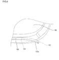
- FIG. 4 is a perspective view illustrating an end portion of a sub seal in a conventional door trim.
- FIG. 1 is an entire view of a door trim 10 according to this embodiment.
- the door trim 10 is mounted as an interior material on a interior side of a door inner panel 50 of a vehicle.
- the door trim 10 has a door trim body 12 molded in a board shape from a synthetic resin material, and the door trim body 12 is equipped with various devices such as an arm rest portion 14 used as an arm rest for a passenger, a speaker 16, a door pocket 18, an inside handle 20, an ornament 22 and the like.
- FIG. 2 is an enlarged perspective view of an A part of the door trim 10 shown in FIG. 1.
- a stepped portion 30 is formed at a lower edge portion 12a of the door trim body 12.
- the stepped portion 30 is formed in a stepped state.
- the stepped portion30 is depressed from a surface portion 12d of the door trim body 12.
- the stepped portion 30 is formed in an elongated state in the longitudinal direction of the vehicle (right and left direction in FIGS. land 2).
- the stepped portion 30 is formed over a corner portion 12c.
- the corner portion 12c is connecting a lower edge portion 12a and right and left side edge portions 12b of the door trim body 12.
- a lengthy sub seal 24 that seals the gap between the door trim body 12 and a scuff plate 40 is mounted on the stepped portion 30.
- the sub seal 24 is a pipe-like member molded from an elastic material such as urethane rubber.
- the sub seal 24 can be molded by an extrusion molding machine, for example.
- the sub seal 24 is mounted by a fitting such as a clip 26 on the stepped portion 30 (See FIG. 3).
- FIG. 3 is a B-B line sectional view of the door trim 10 shown in FIG. 1.
- FIG. 3 illustrates a state where the door trim body 12 is mounted to the interior side of the door inner panel 50 in the vehicle and the sub seal 24 seals the gap between the door trim body 12 and the scuff plate 40.
- a rocker panel 60 constitutes a lower frame of a door-opening of the vehicle.
- the rocker panel 60 is comprised of a rocker outer panel 62 and a rocker inner panel 64.
- the rocker outer panel 62 and the rocker outer panel 64 are bonded at their respective flange portions 62a, 64a.
- a scuff plate 40 covers the flange portions 62a, 64a.
- the scuff plate 40 is molded in the plate shape from a rigid synthetic resin or the like.
- a floor mat 42 is disposed above the rocker inner panel 64, and the scuff plate 40 is disposed so that an outer edge portion 42a of the floor mat 42 in the car width direction is held by an inner edge portion 40a of the scuff plate 40 from above.
- the sub seal 24 has a hollow section substantially in the triangular shape, and a distal end portion 24c of the substantially triangular section of the sub seal 24 is brought into contact with a vertical wall portion 40b formed substantially at the center in the car width direction of the scuff plate 40.
- a weather strip 51 is mounted around the vehicle door.
- the weather strip 51 is mounted surrounding the outside of the sub seal 24. Therefore, the periphery of the vehicle door is sealed doubly by the weather strip 51 and the sub seal 24.
- a vertical wall portion 30a is formed so as to rise toward the interior side of the vehicle.
- the vertical wall portion 30a is formed at the rear end of the stepped portion 30 formed at the lower edge portion 12a of the door trim body 12.
- An insertion hole 32 is provided at the vertical wall portion 30a, and an end portion 24a on the rear side of the vehicle in the sub seal 24 is inserted into the insertion hole 32.
- the door trim 10 of this embodiment since the end portion 24a of the sub seal 24 is inserted into the insertion hole 32, a end face 24b of the end portion 24a of the sub seal 24 is prevented from being exposed to the outside and being seen by passengers. As a result, the door trim 10 with a good appearance and high commercial value can be realized.
- the door trim 10 with the end portion 24a concealed and having a good appearance can be manufactured without increasing the manufacturing cost of the door trim 10.
- the end portion 24a of the sub seal 24 is inserted into the insertion hole 32 and the end portion 24a of the sub seal 24 is supported by the insertion hole 32 in this structure. Thus, the end portion 24a of the sub seal 24 is prevented from hanging downward.
- the sub seal 24 follow along the curved shape of a corner portion 12c connecting the lower edge portion 12a and the side edge portion 12b of the door trim body 12. That is because the end portion 24a of the sub seal 24 is strongly supported by the insertion hole 32.
- corner portion 12c on the rear side of the vehicle ('A' part in FIG. 1) has been described, but the configuration is substantially the same for the corner portion 12c on the front side of the vehicle.
- the sub seal 24 is mounted on the stepped portion 30 with the clip 26 , but not limited to that.
- Means for mounting the sub seal 24 is not particularly limited but the sub seal 24 can be mounted by a metal staple, an engaging claw made of a resin or the like, for example. Alternatively, the sub seal 24 can be mounted onto the surface of the stepped portion 30 with an adhesive.
- stepped portion 30 is provided at the lower edge portion 12a of the door trim body 12 and the sub seal 24 is mounted on the stepped portion 30, but not limited to that.
- the sub seal 24 is mounted to the surface portion 12d of the door trim body 12 and the insertion hole 32 is provided in the vertical wall portion formed so as to rise from the surface portion 12d toward the interior side of the vehicle is also included in the technical scope of the present invention.
Landscapes
- Engineering & Computer Science (AREA)
- Mechanical Engineering (AREA)
- Vehicle Interior And Exterior Ornaments, Soundproofing, And Insulation (AREA)
- Seal Device For Vehicle (AREA)
Abstract
Description
- The present invention relates to a door trim for vehicle provided with a sub seal that seals the gap between a door trim body and a scuff plate.
- As a seal structure around a door when a vehicle door is closed, such a structure has been known that a sub seal made from a lengthy urethane rubber or the like is mounted at a lower edge portion of the door trim for vehicle and the sub seal is brought into contact with a scuff plate disposed on an upper face of a rocker panel of the vehicle (See
Japanese Patent Laid-Open No. 2000-289465 Japanese Utility Model Laid-Open No. 63-16235 Japanese Utility Model Laid-Open No. 63-44821 - However, in the conventional seal structure around the door, terminal of a
lengthy sub seal 100 mounted along the lower edge portion of adoor trim 106 is not processed. Therefore, as shown in FIG. 4, when the vehicle door is opened/closed, a passenger sees ahollow section 102 exposed at anend portion 100a of thesub seal 100, which is not desirable in appearance. There can be methods for closing thehollow section 102 by rounding theend portion 100a of thesub seal 100 or by blocking it with heat welding or the like, but a processing process for theend portion 100a separately from a molding process of thesub seal 100 becomes necessary in this case, which causes a problem of rise in manufacturing costs of thesub seal 100. - Also, in the conventional seal structure around the door, the
sub seal 100 is mounted to the lower edge portion of thedoor trim 106 with afitting 104 such as a clip or staple, but theend portion 100a of thesub seal 100 not supported by thefitting 104 hangs downward, which causes a problem that the hanging end is seen when the door is opened/closed and is not desirable in appearance. - The present invention was made in view of the above circumstances and has an object to improve the appearance of the end portion of the sub seal in the door trim for vehicle in which the sub seal is mounted to the door trim body. Also, another object of the present invention is to prevent the end portion of the sub seal from hanging downward.
- A first invention is a door trim for vehicle in which a sub seal that seals the gap between a door trim body and a scuff plate is mounted, the door trim body being provided with an insertion hole into which at least one of both ends of the sub seal is inserted.
- According to the first invention, since the end portion of the sub seal is inserted into the insertion hole formed at the door trim body, the end portion of the sub seal can be concealed. Therefore, without applying separate processing or the like to the end portion of the sub seal, the section of the end portion of the sub seal is prevented from being exposed to the outside and seen by passengers.
- Also, according to the first invention, since the end portion of the sub seal is inserted into the insertion hole formed at the door trim body, the end portion of the sub seal is supported by the insertion hole. Therefore, the end portion of the sub seal is prevented from hanging downward.
- Moreover, according to the first invention, only by providing an insertion hole in the door trim body, the end portion of the sub seal can be concealed from the view of the passengers with an extremely simple process.
- A second invention is the door trim for vehicle of the first invention in which the sub seal is mounted over a corner portion connecting the lower edge portion and the side edge portion of the door trim body.
- According to the second invention, it is possible to have the sub seal follow the corner portion connecting the lower edge portion and the side edge portion of the door trim body. That is because since the end portion of the sub seal is inserted into the insertion hole, the end portion of the sub seal is supported by the insertion hole so that it does not hang downward. Therefore, even if the sub seal is mounted over the corner portion, the end portion of the sub seal does not hang downward. Therefore, the appearance of the subseal is improved.
- According to the present invention, in the door trim for vehicle in which the sub seal is mounted to the door trim body, the appearance of the end portion of the sub seal can be improved. Also, the end portion of the sub seal can be prevented from hanging downward.
- FIG. 1 is an entire view of a door trim;
- FIG. 2 is an enlarged perspective view of an A part of the door trim shown in FIG. 1;
- FIG. 3 is a B-B line sectional view of the door trim shown in FIG. 1; and
- FIG. 4 is a perspective view illustrating an end portion of a sub seal in a conventional door trim.
- Illustrative embodiment of the present invention will be described below in detail referring to the attached drawings.
- FIG. 1 is an entire view of a
door trim 10 according to this embodiment. - The
door trim 10 is mounted as an interior material on a interior side of a doorinner panel 50 of a vehicle. Thedoor trim 10 has adoor trim body 12 molded in a board shape from a synthetic resin material, and thedoor trim body 12 is equipped with various devices such as anarm rest portion 14 used as an arm rest for a passenger, aspeaker 16, adoor pocket 18, aninside handle 20, anornament 22 and the like. - FIG. 2 is an enlarged perspective view of an A part of the
door trim 10 shown in FIG. 1. - As shown in FIGS. 1 and 2, a
stepped portion 30 is formed at alower edge portion 12a of thedoor trim body 12.
Thestepped portion 30 is formed in a stepped state. The stepped portion30 is depressed from asurface portion 12d of the door trim body 12.Thestepped portion 30 is formed in an elongated state in the longitudinal direction of the vehicle (right and left direction in FIGS. land 2). - Also the
stepped portion 30 is formed over acorner portion 12c. Thecorner portion 12c is connecting alower edge portion 12a and right and leftside edge portions 12b of thedoor trim body 12. Alengthy sub seal 24 that seals the gap between thedoor trim body 12 and ascuff plate 40 is mounted on thestepped portion 30. - The
sub seal 24 is a pipe-like member molded from an elastic material such as urethane rubber. Thesub seal 24 can be molded by an extrusion molding machine, for example. Thesub seal 24 is mounted by a fitting such as aclip 26 on the stepped portion 30 (See FIG. 3). - FIG. 3 is a B-B line sectional view of the
door trim 10 shown in FIG. 1. FIG. 3 illustrates a state where thedoor trim body 12 is mounted to the interior side of the doorinner panel 50 in the vehicle and thesub seal 24 seals the gap between thedoor trim body 12 and thescuff plate 40. - As shown in FIG. 3, a
rocker panel 60 constitutes a lower frame of a door-opening of the vehicle. Therocker panel 60 is comprised of a rockerouter panel 62 and a rockerinner panel 64. The rockerouter panel 62 and the rockerouter panel 64 are bonded at theirrespective flange portions - As shown in FIG. 3, at the upper part of the
rocker panel 60, ascuff plate 40 covers theflange portions scuff plate 40 is molded in the plate shape from a rigid synthetic resin or the like. Afloor mat 42 is disposed above the rockerinner panel 64, and thescuff plate 40 is disposed so that anouter edge portion 42a of thefloor mat 42 in the car width direction is held by aninner edge portion 40a of thescuff plate 40 from above. - As shown in FIG. 3, the
sub seal 24 has a hollow section substantially in the triangular shape, and adistal end portion 24c of the substantially triangular section of thesub seal 24 is brought into contact with avertical wall portion 40b formed substantially at the center in the car width direction of thescuff plate 40. By this arrangement, when the vehicle door is closed, the sub seal 24 seals the gap between thedoor trim body 12 and thescuff plate 40. As a result, intrusion of dusts or water from outside into the compartment and noises such as a road noise are blocked by thesub seal 24. In general, aweather strip 51 is mounted around the vehicle door. Theweather strip 51 is mounted surrounding the outside of thesub seal 24. Therefore, the periphery of the vehicle door is sealed doubly by theweather strip 51 and thesub seal 24. - As shown in FIG. 2, a
vertical wall portion 30a is formed so as to rise toward the interior side of the vehicle. Thevertical wall portion 30a is formed at the rear end of thestepped portion 30 formed at thelower edge portion 12a of thedoor trim body 12. - An
insertion hole 32 is provided at thevertical wall portion 30a, and anend portion 24a on the rear side of the vehicle in thesub seal 24 is inserted into theinsertion hole 32. - Therefore, according to the
door trim 10 of this embodiment, since theend portion 24a of thesub seal 24 is inserted into theinsertion hole 32, aend face 24b of theend portion 24a of thesub seal 24 is prevented from being exposed to the outside and being seen by passengers. As a result, thedoor trim 10 with a good appearance and high commercial value can be realized. - Also, it is only necessary to provide the
insertion hole 32 in thedoor trim body 12, and processing to conceal theend portion 24a of thesub seal 24 can be realized with an extremely simple process. Therefore, thedoor trim 10 with theend portion 24a concealed and having a good appearance can be manufactured without increasing the manufacturing cost of thedoor trim 10. - Also, the
end portion 24a of thesub seal 24 is inserted into theinsertion hole 32 and theend portion 24a of thesub seal 24 is supported by theinsertion hole 32 in this structure. Thus, theend portion 24a of thesub seal 24 is prevented from hanging downward. - Also, according to the
door trim 10 of this embodiment, it is possible to have thesub seal 24 follow along the curved shape of acorner portion 12c connecting thelower edge portion 12a and theside edge portion 12b of thedoor trim body 12.
That is because theend portion 24a of thesub seal 24 is strongly supported by theinsertion hole 32. - Therefore, even if the
sub seal 24 is mounted over thecorner portion 12c, theend portion 24a of thesub seal 24 curved upward is prevented from hanging downward by an elastic return force. - In the above embodiment, the
corner portion 12c on the rear side of the vehicle ('A' part in FIG. 1) has been described, but the configuration is substantially the same for thecorner portion 12c on the front side of the vehicle. - With embodiments of the present invention described above with reference to the accompanying drawings, it is to be understood that the invention is not limited to those precise embodiments, and the embodiments as below, for example, can be within the scope of the present invention.
- (1) In the aboveembodiment, an example in which both end
portions 24a of thesub seal 24 are inserted into theinsertion hole 32, respectively, provided at the doortrim body 12 was shown, but not limited to that. For example, a case where only one of theend portions 24a of thesub seal 24 is inserted into theinsertion hole 32 is also included in the technical scope of the present invention. - (2) In the above embodiment, an example in which the
sub seal 24 is mounted on the steppedportion 30 with theclip 26 was shown, but not limited to that. Means for mounting thesub seal 24 is not particularly limited but thesub seal 24 can be mounted by a metal staple, an engaging claw made of a resin or the like, for example. Alternatively, thesub seal 24 can be mounted onto the surface of the steppedportion 30 with an adhesive. - (3) In the above embodiment, an example in which the
sub seal 24 is molded in a hollow pipe shape was shown, but not limited to that. Thesub seal 24 may be molded in the solid state. - (4) In the above embodiment, an example in which the stepped
portion 30 is provided at thelower edge portion 12a of the doortrim body 12 and thesub seal 24 is mounted on the steppedportion 30, but not limited to that. For example, a case where thesub seal 24 is mounted to thesurface portion 12d of the doortrim body 12 and theinsertion hole 32 is provided in the vertical wall portion formed so as to rise from thesurface portion 12d toward the interior side of the vehicle is also included in the technical scope of the present invention.
Claims (2)
- A door trim for vehicle in which a sub seal that seals the gap between a door trim body and a scuff plate is mounted,
wherein an insertion hole is provided at said door trim body, into which at least one of both ends of said sub seal is inserted. - The door trim for vehicle according to claim 1, wherein said sub seal is mounted over a corner portion connecting a lower edge portion and a side edge portion of said door trim body.
Applications Claiming Priority (1)
| Application Number | Priority Date | Filing Date | Title |
|---|---|---|---|
| JP2006295909A JP4788967B2 (en) | 2006-10-31 | 2006-10-31 | Vehicle door trim |
Publications (3)
| Publication Number | Publication Date |
|---|---|
| EP1918141A2 true EP1918141A2 (en) | 2008-05-07 |
| EP1918141A3 EP1918141A3 (en) | 2009-04-08 |
| EP1918141B1 EP1918141B1 (en) | 2010-10-06 |
Family
ID=39155222
Family Applications (1)
| Application Number | Title | Priority Date | Filing Date |
|---|---|---|---|
| EP07119289A Active EP1918141B1 (en) | 2006-10-31 | 2007-10-25 | Door trim for vehicle |
Country Status (5)
| Country | Link |
|---|---|
| US (1) | US7788853B2 (en) |
| EP (1) | EP1918141B1 (en) |
| JP (1) | JP4788967B2 (en) |
| CN (1) | CN101173587B (en) |
| DE (1) | DE602007009620D1 (en) |
Families Citing this family (14)
| Publication number | Priority date | Publication date | Assignee | Title |
|---|---|---|---|---|
| DE102006049679B4 (en) * | 2006-10-18 | 2010-08-12 | Johnson Controls Interiors Gmbh & Co. Kg | Vehicle door with sealing plane and a sealing element whose ends overlap |
| JP5229533B2 (en) * | 2007-12-05 | 2013-07-03 | トヨタ紡織株式会社 | Door grip mounting structure |
| DE102008007244B4 (en) * | 2008-02-01 | 2010-12-23 | BSH Bosch und Siemens Hausgeräte GmbH | Refrigeration device with a hollow profile-shaped sealing element |
| JP5369520B2 (en) * | 2008-07-14 | 2013-12-18 | トヨタ紡織株式会社 | Vehicle door trim |
| JP5488883B2 (en) * | 2009-10-16 | 2014-05-14 | トヨタ紡織株式会社 | Interior materials for vehicles |
| JP5725820B2 (en) * | 2010-12-02 | 2015-05-27 | 鬼怒川ゴム工業株式会社 | Corner weather forming part of door weather strip |
| JP5915880B2 (en) * | 2011-08-02 | 2016-05-11 | トヨタ紡織株式会社 | Door trim |
| US8814254B1 (en) * | 2012-08-22 | 2014-08-26 | Fifth Wheel Cap LLC | Protective cap for opening in vehicle bed |
| JP6268437B2 (en) * | 2014-06-10 | 2018-01-31 | トヨタ車体株式会社 | Vehicle sliding door structure |
| JP2017077850A (en) * | 2015-10-22 | 2017-04-27 | 本田技研工業株式会社 | Door seal structure |
| CN108263180B (en) * | 2016-12-30 | 2021-04-13 | 佛吉亚汽车内部系统公司 | Personal motor vehicle with reconfigurable passenger compartment |
| US10399513B2 (en) * | 2017-04-10 | 2019-09-03 | Toyota Motor Engineering & Manufacturing North America, Inc. | Vehicle doors including door trim assemblies and vehicles including same |
| USD1037960S1 (en) * | 2022-04-14 | 2024-08-06 | Zhejiang Geely Holding Group Co., Ltd. | Vehicle door panel |
| USD1063756S1 (en) * | 2022-05-10 | 2025-02-25 | Mullen Technologies, Inc. | Vehicle door |
Family Cites Families (15)
| Publication number | Priority date | Publication date | Assignee | Title |
|---|---|---|---|---|
| DE2802140A1 (en) | 1978-01-19 | 1979-07-26 | Daimler Benz Ag | MOTOR CAR WITH AT LEAST ONE DOOR |
| JPS6148850U (en) * | 1984-09-04 | 1986-04-02 | ||
| JPS6316235U (en) | 1986-07-18 | 1988-02-03 | ||
| JPS6344821U (en) | 1986-09-10 | 1988-03-25 | ||
| JPH0622589Y2 (en) * | 1988-10-28 | 1994-06-15 | 西川ゴム工業株式会社 | Door seal device |
| JPH03224846A (en) * | 1990-01-30 | 1991-10-03 | Kinugawa Rubber Ind Co Ltd | End part structure of weather strip |
| US5906409A (en) | 1995-06-06 | 1999-05-25 | Chrysler Corporation | Vehicle door assembly |
| JP3624579B2 (en) | 1996-10-04 | 2005-03-02 | いすゞ自動車株式会社 | Automobile having door seal structure |
| DE29720053U1 (en) * | 1997-11-12 | 1999-03-18 | Meteor Gummiwerke K. H. Bädje GmbH & Co, 31167 Bockenem | Seal connector, seal end piece and seal |
| JP2000289465A (en) | 1999-04-05 | 2000-10-17 | Toyota Motor Corp | Door seal structure |
| US7077450B2 (en) | 2001-09-10 | 2006-07-18 | Nishikawa Rubber Co., Ltd. | Sound-absorbing material for vehicle's lower portion |
| US6997505B2 (en) | 2003-12-30 | 2006-02-14 | Lear Corporation | Modular door trim panel assembly having an integrated seal and method of manufacturing same |
| US7059659B2 (en) * | 2004-07-26 | 2006-06-13 | Lear Corporation | Vehicle door barrier panel having removable attachment tabs |
| CN1730307A (en) * | 2004-08-06 | 2006-02-08 | 丰田合成株式会社 | Weather strips |
| US7240956B2 (en) * | 2005-08-08 | 2007-07-10 | Cadillac Products Automotive Company | Bend flaps for trim panel mounted watershields |
-
2006
- 2006-10-31 JP JP2006295909A patent/JP4788967B2/en active Active
-
2007
- 2007-10-24 US US11/923,073 patent/US7788853B2/en active Active
- 2007-10-25 DE DE602007009620T patent/DE602007009620D1/en active Active
- 2007-10-25 EP EP07119289A patent/EP1918141B1/en active Active
- 2007-10-30 CN CN2007101652017A patent/CN101173587B/en active Active
Also Published As
| Publication number | Publication date |
|---|---|
| CN101173587B (en) | 2013-02-20 |
| JP4788967B2 (en) | 2011-10-05 |
| EP1918141A3 (en) | 2009-04-08 |
| US20080256875A1 (en) | 2008-10-23 |
| JP2008110712A (en) | 2008-05-15 |
| EP1918141B1 (en) | 2010-10-06 |
| US7788853B2 (en) | 2010-09-07 |
| DE602007009620D1 (en) | 2010-11-18 |
| CN101173587A (en) | 2008-05-07 |
Similar Documents
| Publication | Publication Date | Title |
|---|---|---|
| EP1918141B1 (en) | Door trim for vehicle | |
| US8978306B2 (en) | Vehicle seal system | |
| JP5087592B2 (en) | Lower structure of vehicle door | |
| JP6700900B2 (en) | Sealing material for automobile doors | |
| EP2137020A1 (en) | Glass run with integrated upper reveal | |
| JP3054843B2 (en) | Weather strip mounting structure | |
| JP3793690B2 (en) | Automotive door seal structure and parting seal used in the door seal structure | |
| JP4184134B2 (en) | Body side weather strip mounting structure | |
| JP4944431B2 (en) | Grip structure for interior parts | |
| JP6513996B2 (en) | Vehicle door | |
| US8550537B2 (en) | Automotive vehicle passage seal | |
| JP3893675B2 (en) | Opening trim assembly structure | |
| JP2008074187A (en) | Interior parts for automobile | |
| JP2009029297A (en) | Automobile door trim | |
| JP4585112B2 (en) | Car side visor with double seal | |
| JPH0146327B2 (en) | ||
| JP2007152977A (en) | Weather strip for automobile | |
| JP4238704B2 (en) | Weather strip | |
| JP2024022307A (en) | vehicle door | |
| JP2025008581A (en) | Weather stripping | |
| JP3916818B2 (en) | Automobile seal structure | |
| JP2016135644A (en) | Door structure of vehicle | |
| JP2019108127A (en) | Vehicle door | |
| KR20000034557A (en) | Door trim flow prevention structure of automobile | |
| JP2017100613A (en) | Door glass attaching structure |
Legal Events
| Date | Code | Title | Description |
|---|---|---|---|
| PUAI | Public reference made under article 153(3) epc to a published international application that has entered the european phase |
Free format text: ORIGINAL CODE: 0009012 |
|
| AK | Designated contracting states |
Kind code of ref document: A2 Designated state(s): AT BE BG CH CY CZ DE DK EE ES FI FR GB GR HU IE IS IT LI LT LU LV MC MT NL PL PT RO SE SI SK TR |
|
| AX | Request for extension of the european patent |
Extension state: AL BA HR MK RS |
|
| RIN1 | Information on inventor provided before grant (corrected) |
Inventor name: SERIFU, MITSURU,C/O TOYOTA BOSHOKU KABUSHIKI KAISH Inventor name: NARIMATSU, TETSUYA,C/O TOYOTA BOSHOKU KABUSHIKI KA |
|
| RAP1 | Party data changed (applicant data changed or rights of an application transferred) |
Owner name: TOYOTA BOSHOKU KABUSHIKI KAISHA |
|
| PUAL | Search report despatched |
Free format text: ORIGINAL CODE: 0009013 |
|
| AK | Designated contracting states |
Kind code of ref document: A3 Designated state(s): AT BE BG CH CY CZ DE DK EE ES FI FR GB GR HU IE IS IT LI LT LU LV MC MT NL PL PT RO SE SI SK TR |
|
| AX | Request for extension of the european patent |
Extension state: AL BA HR MK RS |
|
| 17P | Request for examination filed |
Effective date: 20090513 |
|
| AKX | Designation fees paid |
Designated state(s): DE |
|
| GRAP | Despatch of communication of intention to grant a patent |
Free format text: ORIGINAL CODE: EPIDOSNIGR1 |
|
| GRAS | Grant fee paid |
Free format text: ORIGINAL CODE: EPIDOSNIGR3 |
|
| GRAA | (expected) grant |
Free format text: ORIGINAL CODE: 0009210 |
|
| RIN1 | Information on inventor provided before grant (corrected) |
Inventor name: NARIMATSU, TETSUYA,C/O TOYOTA BOSHOKU KABUSHIKI KA Inventor name: SERIFU, MITSURU,C/O TOYOTA BOSHOKU KABUSHIKI KAISH |
|
| AK | Designated contracting states |
Kind code of ref document: B1 Designated state(s): DE |
|
| REF | Corresponds to: |
Ref document number: 602007009620 Country of ref document: DE Date of ref document: 20101118 Kind code of ref document: P |
|
| PLBE | No opposition filed within time limit |
Free format text: ORIGINAL CODE: 0009261 |
|
| STAA | Information on the status of an ep patent application or granted ep patent |
Free format text: STATUS: NO OPPOSITION FILED WITHIN TIME LIMIT |
|
| 26N | No opposition filed |
Effective date: 20110707 |
|
| REG | Reference to a national code |
Ref country code: DE Ref legal event code: R097 Ref document number: 602007009620 Country of ref document: DE Effective date: 20110707 |
|
| PGFP | Annual fee paid to national office [announced via postgrant information from national office to epo] |
Ref country code: DE Payment date: 20250902 Year of fee payment: 19 |