EP1918126B1 - Wheel having hubcap clamp mounted to improve wheel balance and method of balancing a wheel using a hubcap clamp - Google Patents
Wheel having hubcap clamp mounted to improve wheel balance and method of balancing a wheel using a hubcap clamp Download PDFInfo
- Publication number
- EP1918126B1 EP1918126B1 EP07119556.4A EP07119556A EP1918126B1 EP 1918126 B1 EP1918126 B1 EP 1918126B1 EP 07119556 A EP07119556 A EP 07119556A EP 1918126 B1 EP1918126 B1 EP 1918126B1
- Authority
- EP
- European Patent Office
- Prior art keywords
- hubcap
- wheel
- hub
- flange
- clamp
- Prior art date
- Legal status (The legal status is an assumption and is not a legal conclusion. Google has not performed a legal analysis and makes no representation as to the accuracy of the status listed.)
- Active
Links
Images



Classifications
-
- B—PERFORMING OPERATIONS; TRANSPORTING
- B60—VEHICLES IN GENERAL
- B60B—VEHICLE WHEELS; CASTORS; AXLES FOR WHEELS OR CASTORS; INCREASING WHEEL ADHESION
- B60B7/00—Wheel cover discs, rings, or the like, for ornamenting, protecting, venting, or obscuring, wholly or in part, the wheel body, rim, hub, or tyre sidewall, e.g. wheel cover discs, wheel cover discs with cooling fins
- B60B7/06—Fastening arrangements therefor
- B60B7/14—Fastening arrangements therefor comprising screw-threaded means
-
- B—PERFORMING OPERATIONS; TRANSPORTING
- B60—VEHICLES IN GENERAL
- B60B—VEHICLE WHEELS; CASTORS; AXLES FOR WHEELS OR CASTORS; INCREASING WHEEL ADHESION
- B60B7/00—Wheel cover discs, rings, or the like, for ornamenting, protecting, venting, or obscuring, wholly or in part, the wheel body, rim, hub, or tyre sidewall, e.g. wheel cover discs, wheel cover discs with cooling fins
- B60B7/0013—Hub caps
-
- B—PERFORMING OPERATIONS; TRANSPORTING
- B60—VEHICLES IN GENERAL
- B60B—VEHICLE WHEELS; CASTORS; AXLES FOR WHEELS OR CASTORS; INCREASING WHEEL ADHESION
- B60B7/00—Wheel cover discs, rings, or the like, for ornamenting, protecting, venting, or obscuring, wholly or in part, the wheel body, rim, hub, or tyre sidewall, e.g. wheel cover discs, wheel cover discs with cooling fins
- B60B7/0026—Wheel cover discs, rings, or the like, for ornamenting, protecting, venting, or obscuring, wholly or in part, the wheel body, rim, hub, or tyre sidewall, e.g. wheel cover discs, wheel cover discs with cooling fins characterised by the surface
- B60B7/0066—Wheel cover discs, rings, or the like, for ornamenting, protecting, venting, or obscuring, wholly or in part, the wheel body, rim, hub, or tyre sidewall, e.g. wheel cover discs, wheel cover discs with cooling fins characterised by the surface the dominant aspect being the surface structure
-
- B—PERFORMING OPERATIONS; TRANSPORTING
- B60—VEHICLES IN GENERAL
- B60B—VEHICLE WHEELS; CASTORS; AXLES FOR WHEELS OR CASTORS; INCREASING WHEEL ADHESION
- B60B7/00—Wheel cover discs, rings, or the like, for ornamenting, protecting, venting, or obscuring, wholly or in part, the wheel body, rim, hub, or tyre sidewall, e.g. wheel cover discs, wheel cover discs with cooling fins
- B60B7/06—Fastening arrangements therefor
- B60B7/061—Fastening arrangements therefor characterised by the part of the wheels to which the discs, rings or the like are mounted
- B60B7/066—Fastening arrangements therefor characterised by the part of the wheels to which the discs, rings or the like are mounted to the hub
-
- B—PERFORMING OPERATIONS; TRANSPORTING
- B64—AIRCRAFT; AVIATION; COSMONAUTICS
- B64C—AEROPLANES; HELICOPTERS
- B64C25/00—Alighting gear
- B64C25/32—Alighting gear characterised by elements which contact the ground or similar surface
- B64C25/34—Alighting gear characterised by elements which contact the ground or similar surface wheeled type, e.g. multi-wheeled bogies
- B64C25/36—Arrangements or adaptations of wheels, tyres or axles in general
Definitions
- the present invention is directed to a wheel having a hubcap connected thereto by a clamp and to a method of clamping a hubcap to a wheel, and, more specifically, toward a wheel having a hubcap clamp mounted in a manner that improves wheel balance and toward a method of positioning a hubcap and clamp to improve wheel balance.
- a wheel having a uniform distribution of mass will spin evenly and can be referred to as balanced. If the mass is not evenly distributed, the wheel will tend to vibrate and/or wobble at high rates of rotation.
- Many wheels, including aircraft wheels, have mass variations caused by the manufacturing process, or by valves or other elements on the wheel that make the distribution of mass on the wheel asymmetric. Wheels are therefore often balanced by adding small weights thereto to compensate for such asymmetries.
- Aircraft wheels may include inflation and safety relief valves that tend to make the distribution of weight uneven. Thus, weights may be added to these wheels during the balancing process to counterbalance the mass of the valves.
- a tire pressure indicator system (TPIS) may also be added to an aircraft wheel after it is balanced. To offset the mass of the TPIS, counterweights are often provided with the TPIS that can be installed opposite the TPIS to substantially maintain wheel balance. Thus a wheel with an inflation valve, a safety valve, a TPIS and a TPIS counterweight is relatively evenly balanced.
- a hubcap may be installed on the wheel after balancing.
- the mass distribution of hubcap itself can be estimated, and it is known to control the orientation of the hubcap with respect to the wheel.
- a hubcap 200 may be provided with projecting pins 202 on a flange 204 which pins are received in openings 206 on a wheel flange 208 to ensure that the hubcap 200 is mounted in a desired angular relationship with the wheel 210.
- the openings 206 in the wheel flange can concentrate stress in an undesirable manner, and it would be beneficial to eliminate such openings.
- the clamp (not illustrated in Fig. 14 ) used to attach the hubcap to the wheel does not have a symmetric mass distribution. Instead, the closure portion of the clamp has more mass than other portions of the clamp. Installing such a clamp on a wheel therefore reduces the balance of the wheel. And, because the clamp can be installed with the closure mechanism in any orientation, the effect of the clamp on the balance of a wheel is difficult to predict.
- DE 36 11 038 describes a wheel unit that comprises a one-piece alloy wheel with a wheel disc provided with a central hub part and with a rim supporting a tire.
- the wheel unit described by DE 36 11 038 also comprises a covering plate, which can be attached to the outside of the wheel disc.
- a first aspect of which is a method of mounting a hubcap on a wheel that has an axis of rotation, an annular hub surrounding the axis of rotation, and an annular web projecting from the annular hub toward a wheel outer periphery.
- the wheel hub includes a first periphery extending along the circumference of a circle surrounding the axis of rotation and a second periphery spaced from the circumference of the circle.
- a hubcap is provided that has a top wall and a cylindrical sidewall extending from the top wall, and the cylindrical sidewall has an end edge spaced from the top wall and a circumferential flange projecting from the cylindrical side wall.
- the circumferential flange in turn has a sidewall and an alignment tab projecting from the sidewall.
- the hubcap alignment tab is aligned with the second periphery, the hubcap sidewall is placed against the hub with the alignment tab over the second periphery, and the hubcap is clamped to the wheel.
- FIG. 1 Another aspect of the invention is a wheel having an axis of rotation, a cylindrical hub surrounding the axis of rotation, and an annular web projecting from the cylindrical hub toward a wheel outer periphery.
- the cylindrical hub includes a first periphery extending along the circumference of a circle surrounding the axis of rotation and a second periphery spaced from the circumference of the circle.
- the wheel also includes a hubcap having a top wall and a cylindrical side wall extending from the top wall, and the cylindrical sidewall has an end edge spaced from the top wall and a circumferential flange projecting from the cylindrical side wall.
- the circumferential flange includes an alignment tab overlying the hub second periphery.
- a clamp is mounted around the hub and the hubcap circumferential flange to hold the hubcap on the wheel, the clamp includes a gap, and the tab is received in the gap.
- a further aspect of the invention comprises a wheel having an axis of rotation, a cylindrical hub surrounding the axis of rotation and an annular web projecting from the cylindrical hub toward a wheel outer periphery.
- a hub flange is spaced from the annular web and projects away from the axis of rotation.
- the hub flange includes a projecting tab.
- a hubcap for mounting on the wheel has a top wall and a cylindrical side wall extending from the top wall.
- the cylindrical sidewall has an end edge spaced from the top wall and a circumferential flange projecting from the cylindrical side wall.
- the circumferential flange in turn, has a first periphery extending along the circumference of a circle and a second periphery spaced from the circumference of the circle.
- the projecting tab is aligned with the hubcap second periphery when the hubcap is mounted on the wheel.
- a clamp is also provided that encircles the hub flange and the hubcap circumferential flange to hold the hubcap on the wheel.
- the clamp has a gap in which the tab is received.
- Fig. 1 is a sectional elevational view of a wheel having a hubcap according to an embodiment of the present invention
- Fig. 2 is an end elevational view of the hubcap of Fig. 1 ;
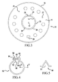
- Fig. 3 is a front elevational view of the wheel of Fig. 1 with the hubcap removed;
- Fig. 4 is a side elevational view of a clamp for holding the hubcap of Fig. 1 on a wheel;
- Fig. 5 is a sectional elevational view taken along line V-V of Fig. 4 ;
- Fig. 6 is a sectional elevational view taken in the direction of line VI-VI in Fig. 1 ;
- Fig. 7 is an elevational view of a hub flange of a wheel according to a second embodiment of the present invention.
- Fig. 8 is an end elevational view of a hubcap usable with the wheel of Fig. 7 ;
- Fig. 9 is an elevational view of a hub flange of a wheel according to a third embodiment of the present invention.
- Fig. 10 is an end elevational view of a hubcap usable with the wheel of Fig. 9 ;
- Fig. 11 is an end elevational view of an alternate hubcap usable with the wheel illustrated in Fig. 3 ;
- Fig. 12 is an elevational view of a wheel having a projecting tab according to a further embodiment of the present invention.
- Fig. 13 is an end elevational a hubcap usable with the wheel of Fig. 12 ;
- Fig. 14 is a sectional elevational view of a conventional hubcap and wheel.
- Figures 1 and 3 illustrate a wheel 10 having an axis of rotation 12 and a hub 14 surrounding the axis of rotation 12.
- An annular web 16 extends from the hub 14 and forms the main body of wheel 10.
- a rim 18 at the outer edge of annular web 16 is illustrated in Fig. 3 .
- Hub 14 includes a hub flange 20 that is spaced from annular web 16 and which extends away from the axis of rotation 12.
- Hub flange 20 has a generally circular periphery, specifically a first peripheral portion 22 that lies on a circle 24 surrounding axis of rotation 12 and a second peripheral portion 26 that is spaced from the circle.
- second periphery 26 is flat or linear and lies along a chord of circle 24.
- Hub flange 20 also includes a first sidewall 28 facing away from annular web 16.
- An inflation valve is mountable at opening 25, a safety relief valve is mountable at opening 27, and a TPIS is mountable at location 29.
- Figures 1 and 2 illustrate a hubcap 30 having a top wall 32 and a sidewall 34 extending from the top wall and terminating at an end edge 36.
- a circumferential flange 38 projects from the sidewall 34 and includes a sidewall 40; an alignment tab 42 projects from sidewall 40.
- Alignment tab 42 is not limited to having a rectangular cross section; an alternate configuration of an alignment tab 70, usable with the wheel of Fig. 3 , is illustrated in Fig. 11 .
- Alignment tab 70 in this configuration has a circular cross section.
- Figs. 4 and 5 illustrate a clamp 50 for holding hubcap 30 on wheel 10.
- Clamp 50 is generally circular and has a V-shaped cross section forming a groove 51 as illustrated in Fig. 5 .
- Clamp 50 has first and second ends 52, 54 that are normally spaced by a gap 56, and first and second fingers 58, 60, projecting from first and second ends 52, 54, respectively.
- a threaded fastener 62 passes through each of first and second fingers 58, 60 and a nut 64 is tightened on threaded fastener 62 to draw first and second ends 52, 54 toward one another and thereby reduce size of gap 56 and the diameter of the clamp 50.
- alignment tab 42 is configured and positioned such that sidewall 40 of hubcap 30 cannot be brought into contact with first sidewall 28 of wheel 10 over its full circumference unless alignment tab 42 is aligned with the second periphery 26 of wheel hub 14. In any other angular relationship, alignment tab 42 will contact wheel hub sidewall 28 and prevent hubcap 30 from being secured to wheel 10 in a proper manner. In this manner, a desired orientation between the hubcap 30 and wheel 10 can be obtained without the use of projecting pins and bores in the hub flange as was previously often necessary.
- clamp 50 With hubcap 30 held against wheel hub 14, clamp 50 is placed around the perimeters of hubcap circumferential flange 38 and hub flange 20 so that portions of the circumferential flange 38 and hub flange 20 are received in groove 51.
- the gap 56 of clamp 50 must be aligned with tab 42 for the clamp 50 to fit properly around the hubcap 30; the alignment tab 42 will help prevent clamp 50 from being attached to hubcap 30 properly if not aligned in this manner.
- Nut 64 and threaded fastener 62 are then tightened to draw the first and second ends 52, 54 of clamp 50 toward one another to reduce the size of gap 56, reduce the diameter or opening size of clamp 50 and to secure hubcap 30 to wheel hub 14.
- the length of threaded fastener may be selected so that threaded fastener 62 is not long enough to connect the first and second ends 52, 54 of the clamp if the clamp is not positioned with tab 42 in gap 56.
- TPIS counterweights are installed at a position opposed to location 29 to balance the mass of the TPIS.
- the later addition of the hubcap clamp with threaded fastener 60 then unbalances the wheel to a certain degree.
- the present inventors have determined that the asymmetric mass of the hubcap clamp threaded fastener 60 can be used to adequately balance the mass of the TPIS without the need for additional TPIS balancing weights if the fastener is installed at a known location with respect to the TPIS. This arrangement results in a lower mass for the wheel and therefore contributes to fuel savings.
- the mass and placement of the inflation valve at location 25 and the safety valve at location 27 and the asymmetric mass of the hubcap can also be taken into account in a well known manner when determining the position for the hubcap clamp.
- FIG. 7 and 8 A second embodiment of the invention is illustrated in Figures 7 and 8 , wherein like reference numerals are used to identify elements common to the first embodiment, and elements different than but related to elements of the first embodiment are identified with like references numerals and primes.
- the second periphery 26' of wheel hub flange 20 is arcuate and cooperates with an arcuate alignment tab 42' on hubcap 30 of Figure 8 .
- Figure 9 illustrates a third embodiment of the invention wherein like reference numerals are used to identify elements common to the first embodiment, and elements different than but related to elements of the first embodiment are identified with like references numerals and double primes.
- a W-shaped second periphery 26" cooperates with a W-shaped alignment tab 42" to ensure a desired alignment between the hub flange 20 and the hubcap 30.
- Other second peripheries having shapes complimentary to the shape of a hubcap alignment tab could be used without exceeding the scope of this invention.
- an alignment tab is formed on a hubcap while an aircraft wheel is provided with a peripheral portion that accommodates the tab on the hubcap.
- the present invention can also be practiced with an alignment tab on a wheel and a suitable hubcap having a portion alignable with the tab.
- a wheel 80 includes an axis of rotation 82, a projecting web 84, a hub 85 and a hub flange 86, the hub flange 86 provided with a projecting alignment tab 88.
- a hubcap 90 illustrated in Fig. 13 , includes a top wall 92, a sidewall 94 terminating in an end edge 96 and a circumferential flange 98.
- Circumferential flange 98 has a first peripheral portion 100 overlying a circle 1010 and a second peripheral portion 102 spaced from the circle 101.
- second portion 102 is linear.
- hubcap 90 must be positioned so that second peripheral portion 102 is aligned with projecting tab 88 on hub flange 86 in order for the hubcap 90 to be installed.
- Hubcap 90 is clamped to wheel 80 with tab 88 located in the gap of a clamp (not shown) in the same manner as the previously described embodiments.
Landscapes
- Engineering & Computer Science (AREA)
- Mechanical Engineering (AREA)
- Aviation & Aerospace Engineering (AREA)
- Connection Of Plates (AREA)
- Clamps And Clips (AREA)
- Brushless Motors (AREA)
Description
- The present invention is directed to a wheel having a hubcap connected thereto by a clamp and to a method of clamping a hubcap to a wheel, and, more specifically, toward a wheel having a hubcap clamp mounted in a manner that improves wheel balance and toward a method of positioning a hubcap and clamp to improve wheel balance.
- A wheel having a uniform distribution of mass will spin evenly and can be referred to as balanced. If the mass is not evenly distributed, the wheel will tend to vibrate and/or wobble at high rates of rotation. Many wheels, including aircraft wheels, have mass variations caused by the manufacturing process, or by valves or other elements on the wheel that make the distribution of mass on the wheel asymmetric. Wheels are therefore often balanced by adding small weights thereto to compensate for such asymmetries.
- Aircraft wheels may include inflation and safety relief valves that tend to make the distribution of weight uneven. Thus, weights may be added to these wheels during the balancing process to counterbalance the mass of the valves. A tire pressure indicator system (TPIS) may also be added to an aircraft wheel after it is balanced. To offset the mass of the TPIS, counterweights are often provided with the TPIS that can be installed opposite the TPIS to substantially maintain wheel balance. Thus a wheel with an inflation valve, a safety valve, a TPIS and a TPIS counterweight is relatively evenly balanced.
- A hubcap may be installed on the wheel after balancing. The mass distribution of hubcap itself can be estimated, and it is known to control the orientation of the hubcap with respect to the wheel. As illustrated in
Figure 14 , ahubcap 200 may be provided with projectingpins 202 on aflange 204 which pins are received inopenings 206 on awheel flange 208 to ensure that thehubcap 200 is mounted in a desired angular relationship with thewheel 210. However, it has been found that theopenings 206 in the wheel flange can concentrate stress in an undesirable manner, and it would be beneficial to eliminate such openings. - Moreover, the clamp (not illustrated in
Fig. 14 ) used to attach the hubcap to the wheel does not have a symmetric mass distribution. Instead, the closure portion of the clamp has more mass than other portions of the clamp. Installing such a clamp on a wheel therefore reduces the balance of the wheel. And, because the clamp can be installed with the closure mechanism in any orientation, the effect of the clamp on the balance of a wheel is difficult to predict. - It is generally desirable to reduce the weight of aircraft components. It would therefore be desirable to reduce the number of weights required to balance an aircraft wheel and to reduce the imbalance imparted to an aircraft wheel by an asymmetrical hubcap clamp.
-
DE 36 11 038 describes a wheel unit that comprises a one-piece alloy wheel with a wheel disc provided with a central hub part and with a rim supporting a tire. The wheel unit described byDE 36 11 038 - These and other problems are addressed by the present invention, a first aspect of which is a method of mounting a hubcap on a wheel that has an axis of rotation, an annular hub surrounding the axis of rotation, and an annular web projecting from the annular hub toward a wheel outer periphery. The wheel hub includes a first periphery extending along the circumference of a circle surrounding the axis of rotation and a second periphery spaced from the circumference of the circle. A hubcap is provided that has a top wall and a cylindrical sidewall extending from the top wall, and the cylindrical sidewall has an end edge spaced from the top wall and a circumferential flange projecting from the cylindrical side wall. The circumferential flange in turn has a sidewall and an alignment tab projecting from the sidewall. The hubcap alignment tab is aligned with the second periphery, the hubcap sidewall is placed against the hub with the alignment tab over the second periphery, and the hubcap is clamped to the wheel.
- Another aspect of the invention is a wheel having an axis of rotation, a cylindrical hub surrounding the axis of rotation, and an annular web projecting from the cylindrical hub toward a wheel outer periphery. The cylindrical hub includes a first periphery extending along the circumference of a circle surrounding the axis of rotation and a second periphery spaced from the circumference of the circle. The wheel also includes a hubcap having a top wall and a cylindrical side wall extending from the top wall, and the cylindrical sidewall has an end edge spaced from the top wall and a circumferential flange projecting from the cylindrical side wall. The circumferential flange includes an alignment tab overlying the hub second periphery. A clamp is mounted around the hub and the hubcap circumferential flange to hold the hubcap on the wheel, the clamp includes a gap, and the tab is received in the gap.
- A further aspect of the invention comprises a wheel having an axis of rotation, a cylindrical hub surrounding the axis of rotation and an annular web projecting from the cylindrical hub toward a wheel outer periphery. A hub flange is spaced from the annular web and projects away from the axis of rotation. The hub flange includes a projecting tab. A hubcap for mounting on the wheel has a top wall and a cylindrical side wall extending from the top wall. The cylindrical sidewall has an end edge spaced from the top wall and a circumferential flange projecting from the cylindrical side wall. The circumferential flange, in turn, has a first periphery extending along the circumference of a circle and a second periphery spaced from the circumference of the circle. The projecting tab is aligned with the hubcap second periphery when the hubcap is mounted on the wheel. A clamp is also provided that encircles the hub flange and the hubcap circumferential flange to hold the hubcap on the wheel. The clamp has a gap in which the tab is received.
- These and other aspects and features of embodiments of the present invention will be better understood after reading the following detailed description in connection with the attached drawings wherein:
-
Fig. 1 is a sectional elevational view of a wheel having a hubcap according to an embodiment of the present invention; -
Fig. 2 is an end elevational view of the hubcap ofFig. 1 ; -
Fig. 3 is a front elevational view of the wheel ofFig. 1 with the hubcap removed; -
Fig. 4 is a side elevational view of a clamp for holding the hubcap ofFig. 1 on a wheel; -
Fig. 5 is a sectional elevational view taken along line V-V ofFig. 4 ; -
Fig. 6 is a sectional elevational view taken in the direction of line VI-VI inFig. 1 ; -
Fig. 7 is an elevational view of a hub flange of a wheel according to a second embodiment of the present invention; -
Fig. 8 is an end elevational view of a hubcap usable with the wheel ofFig. 7 ; -
Fig. 9 is an elevational view of a hub flange of a wheel according to a third embodiment of the present invention; -
Fig. 10 is an end elevational view of a hubcap usable with the wheel ofFig. 9 ; -
Fig. 11 is an end elevational view of an alternate hubcap usable with the wheel illustrated inFig. 3 ; -
Fig. 12 is an elevational view of a wheel having a projecting tab according to a further embodiment of the present invention; -
Fig. 13 is an end elevational a hubcap usable with the wheel ofFig. 12 ; and -
Fig. 14 is a sectional elevational view of a conventional hubcap and wheel. - Referring now to the drawings, wherein the showings are for purposes of illustrating preferred embodiments of the invention only, and not for the purpose of limiting same,
Figures 1 and3 illustrate awheel 10 having an axis ofrotation 12 and ahub 14 surrounding the axis ofrotation 12. Anannular web 16 extends from thehub 14 and forms the main body ofwheel 10. Arim 18 at the outer edge ofannular web 16 is illustrated inFig. 3 .Hub 14 includes ahub flange 20 that is spaced fromannular web 16 and which extends away from the axis ofrotation 12.Hub flange 20 has a generally circular periphery, specifically a firstperipheral portion 22 that lies on acircle 24 surrounding axis ofrotation 12 and a secondperipheral portion 26 that is spaced from the circle. In this embodiment,second periphery 26 is flat or linear and lies along a chord ofcircle 24.Hub flange 20 also includes afirst sidewall 28 facing away fromannular web 16. An inflation valve is mountable at opening 25, a safety relief valve is mountable at opening 27, and a TPIS is mountable atlocation 29. -
Figures 1 and 2 illustrate ahubcap 30 having atop wall 32 and asidewall 34 extending from the top wall and terminating at anend edge 36. Acircumferential flange 38 projects from thesidewall 34 and includes asidewall 40; analignment tab 42 projects fromsidewall 40.Alignment tab 42 is not limited to having a rectangular cross section; an alternate configuration of analignment tab 70, usable with the wheel ofFig. 3 , is illustrated inFig. 11 .Alignment tab 70 in this configuration has a circular cross section. -
Figs. 4 and 5 illustrate aclamp 50 for holdinghubcap 30 onwheel 10.Clamp 50 is generally circular and has a V-shaped cross section forming agroove 51 as illustrated inFig. 5 .Clamp 50 has first and second ends 52, 54 that are normally spaced by agap 56, and first andsecond fingers fastener 62 passes through each of first andsecond fingers nut 64 is tightened on threadedfastener 62 to draw first and second ends 52, 54 toward one another and thereby reduce size ofgap 56 and the diameter of theclamp 50. - As will be appreciated from
Fig. 6 ,alignment tab 42 is configured and positioned such thatsidewall 40 ofhubcap 30 cannot be brought into contact withfirst sidewall 28 ofwheel 10 over its full circumference unlessalignment tab 42 is aligned with thesecond periphery 26 ofwheel hub 14. In any other angular relationship,alignment tab 42 will contactwheel hub sidewall 28 and preventhubcap 30 from being secured towheel 10 in a proper manner. In this manner, a desired orientation between thehubcap 30 andwheel 10 can be obtained without the use of projecting pins and bores in the hub flange as was previously often necessary. Withhubcap 30 held againstwheel hub 14,clamp 50 is placed around the perimeters of hubcapcircumferential flange 38 andhub flange 20 so that portions of thecircumferential flange 38 andhub flange 20 are received ingroove 51. Thegap 56 ofclamp 50 must be aligned withtab 42 for theclamp 50 to fit properly around thehubcap 30; thealignment tab 42 will help preventclamp 50 from being attached tohubcap 30 properly if not aligned in this manner.Nut 64 and threadedfastener 62 are then tightened to draw the first and second ends 52, 54 ofclamp 50 toward one another to reduce the size ofgap 56, reduce the diameter or opening size ofclamp 50 and to securehubcap 30 towheel hub 14. The length of threaded fastener may be selected so that threadedfastener 62 is not long enough to connect the first and second ends 52, 54 of the clamp if the clamp is not positioned withtab 42 ingap 56. - Generally, TPIS counterweights are installed at a position opposed to
location 29 to balance the mass of the TPIS. The later addition of the hubcap clamp with threadedfastener 60, however, then unbalances the wheel to a certain degree. The present inventors have determined that the asymmetric mass of the hubcap clamp threadedfastener 60 can be used to adequately balance the mass of the TPIS without the need for additional TPIS balancing weights if the fastener is installed at a known location with respect to the TPIS. This arrangement results in a lower mass for the wheel and therefore contributes to fuel savings. The mass and placement of the inflation valve atlocation 25 and the safety valve atlocation 27 and the asymmetric mass of the hubcap can also be taken into account in a well known manner when determining the position for the hubcap clamp. - A second embodiment of the invention is illustrated in
Figures 7 and 8 , wherein like reference numerals are used to identify elements common to the first embodiment, and elements different than but related to elements of the first embodiment are identified with like references numerals and primes. In this embodiment, the second periphery 26' ofwheel hub flange 20 is arcuate and cooperates with an arcuate alignment tab 42' onhubcap 30 ofFigure 8 . -
Figure 9 illustrates a third embodiment of the invention wherein like reference numerals are used to identify elements common to the first embodiment, and elements different than but related to elements of the first embodiment are identified with like references numerals and double primes. In this embodiment, a W-shapedsecond periphery 26" cooperates with a W-shapedalignment tab 42" to ensure a desired alignment between thehub flange 20 and thehubcap 30. Other second peripheries having shapes complimentary to the shape of a hubcap alignment tab could be used without exceeding the scope of this invention. - As described hereinabove, an alignment tab is formed on a hubcap while an aircraft wheel is provided with a peripheral portion that accommodates the tab on the hubcap. However, the present invention can also be practiced with an alignment tab on a wheel and a suitable hubcap having a portion alignable with the tab. With reference to
Fig. 12 , awheel 80 includes an axis ofrotation 82, a projectingweb 84, a hub 85 and ahub flange 86, thehub flange 86 provided with a projectingalignment tab 88. A hubcap 90, illustrated inFig. 13 , includes atop wall 92, asidewall 94 terminating in anend edge 96 and acircumferential flange 98.Circumferential flange 98 has a firstperipheral portion 100 overlying a circle 1010 and a secondperipheral portion 102 spaced from thecircle 101. InFig. 13 ,second portion 102 is linear. In this embodiment, hubcap 90 must be positioned so that secondperipheral portion 102 is aligned with projectingtab 88 onhub flange 86 in order for the hubcap 90 to be installed. Hubcap 90 is clamped towheel 80 withtab 88 located in the gap of a clamp (not shown) in the same manner as the previously described embodiments. - The present invention has been described herein in terms of several presently preferred embodiments. Obvious additions and modifications to these embodiments will become apparent to those skilled in the relevant art upon a reading of the foregoing disclosure. It is intended that all such obvious additions and modifications form a part of the present invention to the extent they fall within the scope of the several claims appended hereto.
Claims (8)
- A method of mounting a hubcap (30) on a wheel (10), the method comprising:aligning the hubcap (30) with the wheel (10), the wheel comprising an axis of rotation (12), an annular hub (14) surrounding the axis of rotation, and an annular web (16) projecting from the annular hub toward a wheel outer periphery, and the hub comprising a first periphery (22) extending along the circumference of a circle (24) surrounding the axis of rotation and a second periphery (26, 26', 26") spaced from the circumference of the circle and a hub flange (20) projecting from the hub and spaced from the annular web, wherein the first periphery and the second periphery are located on the hub flange, and the hubcap comprising a top wall (32) and a hubcap cylindrical sidewall (34) extending from the top wall, the hubcap cylindrical sidewall comprising an end edge (36) spaced from the top wall and a hubcap circumferential flange (38) projecting from the hubcap cylindrical sidewall, the hubcap circumferential flange comprising a hubcap circumferential flange sidewall (40) and a hubcap alignment tab (42, 42', 42", 70) projecting from the flange sidewall (40), wherein aligning the hubcap with the wheel comprises aligning the hubcap alignment tab with the second periphery;placing the flange sidewall (40) against the hub and the alignment tab over the second periphery, wherein placing the flange sidewall against the hub comprises placing the sidewall against the hub flange (20); andclamping the hubcap to the wheel with a clamp (50) defining a gap (56), wherein clamping the hubcap to the wheel with the clamp comprises placing the clamp around the hub flange (20) and the hubcap circumferential flange (38), and wherein the tab (42, 42', 42", 70) is received in the gap.
- The method of claim 1, wherein the hub flange (20) includes a hub flange sidewall (28) and placing the hubcap circumferential flange sidewall (40) against the hub flange (20) comprises placing the hubcap circumferential flange sidewall against the hub flange sidewall.
- The method of claim 1, wherein the hubcap circumferential flange (38) is spaced from the end edge (36) and placing the hubcap circumferential flange sidewall (40) against the hub flange sidewall (28) comprises inserting the end edge into the hub.
- The method of claim 1, wherein the clamp (50) comprises first and second ends (52, 54) and a closure element (62, 64) for drawing the first end toward the second end, and wherein clamping the hubcap (30) to the wheel (10) comprises:placing the clamp (50) around the hubcap circumferential flange (38) and the hub flange (20) with the alignment tab (42, 42', 42", 70) between the clamp and the first end and the clamp second end; anddrawing the first end toward the second end with the closure element.
- The method of claim 1, wherein the clamp (50) defines a gap (56) and a closure element (62, 64) for reducing a diameter of the clamp, and wherein clamping the hubcap (30) to the wheel (10) comprises:placing the clamp around the hubcap circumferential flange (38) and the hub flange (20) with the alignment tab (42, 42', 42", 70) in the gap; andreducing the diameter of the clamp with the closure element.
- The method of claim 5, wherein reducing the diameter of the clamp with the closure element comprises reducing the size of the gap with the closure element.
- A system comprising:a wheel (10) comprising an axis of rotation (12), the wheel comprising:a cylindrical hub (14) surrounding the axis of rotation (12), wherein the cylindrical hub (14) comprises a hub flange (20), a first periphery (22) extending along the circumference of a circle (24) surrounding the axis of rotation (12), and a second periphery (26, 26', 26") spaced from the circumference of the circle (24), wherein the first periphery and the second periphery are located on the hub flange; andan annular web (16) projecting from the cylindrical hub (14) toward a wheel outer periphery (18);a hubcap (30) comprising a top wall (32) and a hubcap cylindrical side wall (34) extending from the top wall (32), the hubcap cylindrical sidewall (34) comprising an end edge (36) spaced from the top wall (32) and a hubcap circumferential flange (38) projecting from the cylindrical side wall (36), the circumferential flange (38) further including an alignment tab (42, 42', 42", 10) overlying the hub second periphery (26, 26', 26"); and a clamp (50) around the hub flange (20) of the hub (14) and the hubcap circumferential flange (38) holding the hubcap (30) on the wheel (10), the clamp (50) including a gap (56) and the tab (42, 42', 42", 70) being received in the gap (56).
- A system comprising:a wheel (80) comprising an axis of rotation (82) and a cylindrical hub (85) surrounding the axis of rotation (82) and including an annular web (84) projecting from the cylindrical hub (85) toward a wheel outer periphery and a hub flange (86) spaced from the annular web (84) and projecting away from the axis of rotation, the hub flange (86) including a projecting tab (88);a hubcap (90) comprising a top wall (92) and a hubcap cylindrical side wall (94) extending from the top wall (92), the cylindrical sidewall (94) comprising an edge (96) spaced from the top wall (92) and a circumferential flange (98) projecting from the cylindrical side wall (94), the circumferential flange (98) comprising a first periphery (100) extending along the circumference of a circle (101) and a second periphery (102) spaced from the circumference of the circle (101), the projecting tab (88) being aligned with the hubcap second periphery (102); anda clamp (50) around the hub flange (86) and the hubcap circumferential flange (98) holding the hubcap (90) on the wheel (80), the clamp (50) including a gap (56) and the tab (88) being received in the gap (56).
Applications Claiming Priority (1)
| Application Number | Priority Date | Filing Date | Title |
|---|---|---|---|
| US11/589,191 US7712842B2 (en) | 2006-10-30 | 2006-10-30 | Wheel having hubcap clamp mounted to improve wheel balance and method of balancing a wheel using a hubcap clamp |
Publications (3)
| Publication Number | Publication Date |
|---|---|
| EP1918126A2 EP1918126A2 (en) | 2008-05-07 |
| EP1918126A3 EP1918126A3 (en) | 2010-06-02 |
| EP1918126B1 true EP1918126B1 (en) | 2013-04-24 |
Family
ID=39169009
Family Applications (1)
| Application Number | Title | Priority Date | Filing Date |
|---|---|---|---|
| EP07119556.4A Active EP1918126B1 (en) | 2006-10-30 | 2007-10-29 | Wheel having hubcap clamp mounted to improve wheel balance and method of balancing a wheel using a hubcap clamp |
Country Status (2)
| Country | Link |
|---|---|
| US (1) | US7712842B2 (en) |
| EP (1) | EP1918126B1 (en) |
Families Citing this family (3)
| Publication number | Priority date | Publication date | Assignee | Title |
|---|---|---|---|---|
| FR3019097B1 (en) * | 2014-03-28 | 2018-07-06 | Continental Automotive France | ELECTRONIC UNIT FOR MEASURING OPERATING PARAMETERS OF A VEHICLE WHEEL |
| US10562342B2 (en) * | 2016-06-17 | 2020-02-18 | Goodrich Corporation | Aircraft wheel hub cap attachment flange stress relieving pockets |
| US11845347B2 (en) | 2021-05-12 | 2023-12-19 | David Alan Copeland | Precision charging control of an untethered vehicle with a modular vehicle charging roadway |
Family Cites Families (20)
| Publication number | Priority date | Publication date | Assignee | Title |
|---|---|---|---|---|
| US292306A (en) * | 1884-01-22 | Joint for air-pipes | ||
| US1954140A (en) * | 1931-10-14 | 1934-04-10 | Lyon George Albert | Construction for ornamenting rims |
| US2159881A (en) * | 1934-11-21 | 1939-05-23 | Kelsey Hayes Wheel Co | Wheel cover |
| FR971608A (en) * | 1947-09-16 | 1951-01-19 | ||
| JPS5543916U (en) * | 1978-09-18 | 1980-03-22 | ||
| US4270805A (en) * | 1979-04-06 | 1981-06-02 | Spisak Edward G | Wheel and hub cap assembly |
| US4447092A (en) * | 1980-01-22 | 1984-05-08 | Ni Industries, Inc. | Wheel trim retention |
| US4470638A (en) * | 1982-09-30 | 1984-09-11 | Bartco Industries, Inc. | Hubcap attachment |
| DE3611038A1 (en) | 1985-10-19 | 1987-04-23 | Int Technical Research S A H | Light alloy wheel with a covering plate |
| JPH031802U (en) * | 1989-05-29 | 1991-01-10 | ||
| JPH0332903A (en) * | 1989-06-30 | 1991-02-13 | Kanai Hiroyuki | Wheel cap |
| US5020861A (en) * | 1990-03-08 | 1991-06-04 | The Boeing Company | Aircraft wheel hubcap |
| US5303800A (en) * | 1992-09-23 | 1994-04-19 | Kenneth Persson | Closed lubrication system for wheel hub bearings |
| US6152537A (en) * | 1997-08-25 | 2000-11-28 | Phoenix Usa, Inc. | System for attaching a wheel liner to a wheel using a clip |
| US6378954B1 (en) * | 2000-10-16 | 2002-04-30 | John G. Polka | Method and apparatus for covering the distal end of an axle of a wheel |
| US6467852B1 (en) * | 2000-11-09 | 2002-10-22 | John G. Polka | Attachment for retaining a covering over the axle hub of a wheel |
| US20040160115A1 (en) * | 2003-02-13 | 2004-08-19 | Allsop M. Sid | Hub cap having an air valve for bearing cavity pressurization |
| US7438367B2 (en) * | 2003-02-13 | 2008-10-21 | Allsop M Sid | Hub cap having an air valve for bearing cavity pressurization |
| US6758531B1 (en) * | 2003-05-10 | 2004-07-06 | Skf Usa Inc. | Hub and hubcap |
| DE10347800A1 (en) * | 2003-10-10 | 2005-05-19 | Aldo Vanetta | Method for mounting a tire on a rim and balance weight element for attachment to a rim |
-
2006
- 2006-10-30 US US11/589,191 patent/US7712842B2/en active Active
-
2007
- 2007-10-29 EP EP07119556.4A patent/EP1918126B1/en active Active
Also Published As
| Publication number | Publication date |
|---|---|
| US7712842B2 (en) | 2010-05-11 |
| EP1918126A3 (en) | 2010-06-02 |
| US20080100128A1 (en) | 2008-05-01 |
| EP1918126A2 (en) | 2008-05-07 |
Similar Documents
| Publication | Publication Date | Title |
|---|---|---|
| US4561035A (en) | Method and apparatus for clamping and balancing rotatable members | |
| EP2260215B1 (en) | Outboard hub barrel mounted rotor | |
| US7249804B2 (en) | Wheel balancing weight with half-clip | |
| EP1918126A2 (en) | Wheel having hubcap clamp mounted to improve wheel balance and method of balancing a wheel using a hubcap clamp | |
| US20050104439A1 (en) | Wheel weight with body having recess and clip secured therein | |
| US5074578A (en) | Wheel camber and brake caliper adjustment shim | |
| US6238006B1 (en) | Vehicle wheel having a balance weight retention shoulder | |
| AU2007314153A1 (en) | Wheel construction | |
| US12403731B2 (en) | Tire valve | |
| US7178390B1 (en) | Mounting assembly for tire pressure transducer | |
| US10823252B2 (en) | Device for enabling alterations in the extension of vehicle shocks | |
| EP1773607B1 (en) | Tire/wheel assembly | |
| JP2007510135A5 (en) | ||
| JP2007510135A (en) | Method of attaching tire to wheel rim and counterbalance weight attached to wheel rim | |
| CN101516641B (en) | Units for supporting the axles of microcars | |
| US4522612A (en) | Balanced pulley construction | |
| JP3557600B2 (en) | Correction and assembling method of imbalance of tire wheel assembly | |
| US20080060425A1 (en) | Methods and systems for balancing spoked wheels using weight behind a single spoke | |
| US7098780B2 (en) | Device for fixing a tire monitoring system module to a wheel | |
| US7077006B2 (en) | High-accuracy wheel spacer | |
| JP2009092105A (en) | Vehicular wheel, manufacturing method of vehicular wheel, and wheel weight balance adjustment method of vehicular wheel | |
| CN100359216C (en) | Cylinder head gasket including edge-to-edge stop ring | |
| US12168368B2 (en) | Wheel spacer disc for motor vehicles | |
| CN111361354B (en) | Steel wheel and vehicle having the same | |
| RU2657599C1 (en) | Self-adhesive balancing weight for a wheel of a vehicle |
Legal Events
| Date | Code | Title | Description |
|---|---|---|---|
| PUAI | Public reference made under article 153(3) epc to a published international application that has entered the european phase |
Free format text: ORIGINAL CODE: 0009012 |
|
| 17P | Request for examination filed |
Effective date: 20071029 |
|
| AK | Designated contracting states |
Kind code of ref document: A2 Designated state(s): AT BE BG CH CY CZ DE DK EE ES FI FR GB GR HU IE IS IT LI LT LU LV MC MT NL PL PT RO SE SI SK TR |
|
| AX | Request for extension of the european patent |
Extension state: AL BA HR MK RS |
|
| PUAL | Search report despatched |
Free format text: ORIGINAL CODE: 0009013 |
|
| RIC1 | Information provided on ipc code assigned before grant |
Ipc: B64C 25/36 20060101ALI20100419BHEP Ipc: B60B 7/00 20060101AFI20080320BHEP |
|
| AK | Designated contracting states |
Kind code of ref document: A3 Designated state(s): AT BE BG CH CY CZ DE DK EE ES FI FR GB GR HU IE IS IT LI LT LU LV MC MT NL PL PT RO SE SI SK TR |
|
| AX | Request for extension of the european patent |
Extension state: AL BA HR MK RS |
|
| 17Q | First examination report despatched |
Effective date: 20100621 |
|
| AKX | Designation fees paid |
Designated state(s): DE FR GB |
|
| RIC1 | Information provided on ipc code assigned before grant |
Ipc: B60B 7/00 20060101AFI20121127BHEP Ipc: B64C 25/36 20060101ALI20121127BHEP |
|
| GRAP | Despatch of communication of intention to grant a patent |
Free format text: ORIGINAL CODE: EPIDOSNIGR1 |
|
| GRAS | Grant fee paid |
Free format text: ORIGINAL CODE: EPIDOSNIGR3 |
|
| GRAA | (expected) grant |
Free format text: ORIGINAL CODE: 0009210 |
|
| AK | Designated contracting states |
Kind code of ref document: B1 Designated state(s): DE FR GB |
|
| REG | Reference to a national code |
Ref country code: GB Ref legal event code: FG4D |
|
| REG | Reference to a national code |
Ref country code: DE Ref legal event code: R096 Ref document number: 602007029959 Country of ref document: DE Effective date: 20130620 |
|
| PLBE | No opposition filed within time limit |
Free format text: ORIGINAL CODE: 0009261 |
|
| STAA | Information on the status of an ep patent application or granted ep patent |
Free format text: STATUS: NO OPPOSITION FILED WITHIN TIME LIMIT |
|
| 26N | No opposition filed |
Effective date: 20140127 |
|
| REG | Reference to a national code |
Ref country code: DE Ref legal event code: R097 Ref document number: 602007029959 Country of ref document: DE Effective date: 20140127 |
|
| REG | Reference to a national code |
Ref country code: FR Ref legal event code: PLFP Year of fee payment: 10 |
|
| REG | Reference to a national code |
Ref country code: FR Ref legal event code: PLFP Year of fee payment: 11 |
|
| REG | Reference to a national code |
Ref country code: FR Ref legal event code: PLFP Year of fee payment: 12 |
|
| P01 | Opt-out of the competence of the unified patent court (upc) registered |
Effective date: 20230525 |
|
| PGFP | Annual fee paid to national office [announced via postgrant information from national office to epo] |
Ref country code: DE Payment date: 20251028 Year of fee payment: 19 |
|
| PGFP | Annual fee paid to national office [announced via postgrant information from national office to epo] |
Ref country code: GB Payment date: 20251023 Year of fee payment: 19 |
|
| PGFP | Annual fee paid to national office [announced via postgrant information from national office to epo] |
Ref country code: FR Payment date: 20251027 Year of fee payment: 19 |