EP1917162B1 - Closing device for a filler neck disposed on a container - Google Patents
Closing device for a filler neck disposed on a container Download PDFInfo
- Publication number
- EP1917162B1 EP1917162B1 EP06761281A EP06761281A EP1917162B1 EP 1917162 B1 EP1917162 B1 EP 1917162B1 EP 06761281 A EP06761281 A EP 06761281A EP 06761281 A EP06761281 A EP 06761281A EP 1917162 B1 EP1917162 B1 EP 1917162B1
- Authority
- EP
- European Patent Office
- Prior art keywords
- situated
- closing device
- seal
- closure element
- container
- Prior art date
- Legal status (The legal status is an assumption and is not a legal conclusion. Google has not performed a legal analysis and makes no representation as to the accuracy of the status listed.)
- Not-in-force
Links
Images


Classifications
-
- B—PERFORMING OPERATIONS; TRANSPORTING
- B65—CONVEYING; PACKING; STORING; HANDLING THIN OR FILAMENTARY MATERIAL
- B65D—CONTAINERS FOR STORAGE OR TRANSPORT OF ARTICLES OR MATERIALS, e.g. BAGS, BARRELS, BOTTLES, BOXES, CANS, CARTONS, CRATES, DRUMS, JARS, TANKS, HOPPERS, FORWARDING CONTAINERS; ACCESSORIES, CLOSURES, OR FITTINGS THEREFOR; PACKAGING ELEMENTS; PACKAGES
- B65D90/00—Component parts, details or accessories for large containers
- B65D90/10—Manholes; Inspection openings; Covers therefor
-
- B—PERFORMING OPERATIONS; TRANSPORTING
- B60—VEHICLES IN GENERAL
- B60P—VEHICLES ADAPTED FOR LOAD TRANSPORTATION OR TO TRANSPORT, TO CARRY, OR TO COMPRISE SPECIAL LOADS OR OBJECTS
- B60P3/00—Vehicles adapted to transport, to carry or to comprise special loads or objects
- B60P3/22—Tank vehicles
- B60P3/224—Tank vehicles comprising auxiliary devices, e.g. for unloading or level indicating
- B60P3/226—Arrangements of access openings or covers therefor
-
- B—PERFORMING OPERATIONS; TRANSPORTING
- B65—CONVEYING; PACKING; STORING; HANDLING THIN OR FILAMENTARY MATERIAL
- B65D—CONTAINERS FOR STORAGE OR TRANSPORT OF ARTICLES OR MATERIALS, e.g. BAGS, BARRELS, BOTTLES, BOXES, CANS, CARTONS, CRATES, DRUMS, JARS, TANKS, HOPPERS, FORWARDING CONTAINERS; ACCESSORIES, CLOSURES, OR FITTINGS THEREFOR; PACKAGING ELEMENTS; PACKAGES
- B65D90/00—Component parts, details or accessories for large containers
- B65D90/54—Gates or closures
- B65D90/58—Gates or closures having closure members sliding in the plane of the opening
- B65D90/582—Gates or closures having closure members sliding in the plane of the opening having a rotational motion
- B65D90/585—Gates or closures having closure members sliding in the plane of the opening having a rotational motion around an axis perpendicular to the valve port
Definitions
- the invention relates to a closing device for arranged on a container A filler neck, according to the preamble of claim 1, in particular arranged on a rail or road vehicle and designed for loading with powdery or granular bulk solids container.
- WO 02/074581 A1 is a arranged on a rail or road vehicle and for loading powdery or granular bulk materials a hopper (silo) feedable container known, for example, has two spaced at the top of each other and in each case via a passage opening in communication with the interior of the container filler neck , which are each provided with a closing device arranged thereon.
- the individual closing device comprises a cover hood which is mounted on the outside of the filler neck and can be pivoted relative thereto and, in the interior, a closure element pivotable relative to the passage opening about the vertical axis of a pivoting device.
- the cover (weather protection) arranged on the filler neck is first removed or pivoted open relative to the filler neck, and then the inner closure element is manually pivoted about the vertical axis of the pivoting device by means of additional aids. Subsequently, a loading head connected to a silo container is introduced into the passage opening of the filler neck or into the interior of the container and after loading removed again.
- a loading head connected to a silo container is introduced into the passage opening of the filler neck or into the interior of the container and after loading removed again.
- the invention has for its object to provide for the arranged on a container of the type mentioned filler neck for operating the outside and inside arranged closure elements designed closing device, which overcomes the disadvantages of the mentioned prior art and with suitable means with respect to the Filler oriented and controlled relative movement of the two closure elements and an exact sealing of the same with respect to the filler neck ensures.
- the closing device is characterized in that at least one seal has a pressure chamber oriented in the circumferential direction and in communication with at least one connecting member and a supply line, which can be pressurized in the closed position and pressure-relieved for the open position of the closing elements.
- the closing device With the closing device according to the invention a controllable and largely automatic pivoting movement of the two closure elements and by means of the pressurizable seals or lowering and pressing of the outer closure element by means of a compression spring to a manhole seal an exact sealing and thus a high degree of automation of the loading process is achieved.
- the pivoting movement of the two closure elements can also by sending a the Closing device activating signal, for example, done by a non-stationary transmitter.
- closure elements are arranged on the vertical axis and operatively connected so that they are simultaneously and pivotally relative to the passage opening of the filler neck.
- seals arranged in the closure element or in the insert body of the filler neck are exchangeably inserted in the correspondingly formed recesses and fastened by at least one screw connection arranged on the circumference of the seal.
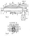
- Fig.1 shows the schematically illustrated silo container of a bulk material loading station, not shown in detail, in particular for powdery or granular bulk materials.
- the silo container 1, a arranged on a rail vehicle 10 container 5 is supplied for loading with the bulk material.
- the container 5 can be arranged on a loading station can be fed to the road vehicle.
- the in Fig.1 container 5 shown in view has, for example, two in the axial direction at a distance from each other arranged filler neck 3, which in each case for introducing a arranged on the silo 1 loading head 2 are formed.
- the single filler neck 3 is about a in Fig.1 not shown passage opening with the container interior 6 in connection.
- For closing and opening the passage opening is at each filler neck 3 a with respect to the container interior 6 or to the container wall 7 on the outside and an inside arranged and in Fig.1 not shown in detail closure element provided.
- the closure elements are each at an in Fig.1 arranged pivoting device 30 and pivotable about a vertical axis in the horizontal plane relative to the passage opening of the filler neck 3.
- the pivoting movement of the closure elements for the outside and inside opening or closing of the passage opening is preferably carried out simultaneously.
- the outside of the container 5 arranged and attached to the pivoting device 30 closure element is preferably designed as a weather protection.
- a power source 16 and an actuatable electrical switching device 26 operating unit 15 is arranged at the one end of the rail vehicle 10 on the platform 9 .
- the compressed air tank 17 and the power source 16 and the switching device 26 are arranged in a housing 18 and are each supplied via a power supply, not shown, with compressed air or electrical energy.
- a source of energy is for example a compressed air cylinder with a volume of 50 l and 200 bar.
- line channel 19 is arranged at the lockable housing 18 a further reaching to the top of the container 5 line channel 19 is arranged.
- the power source 16 and the switching device 26 and on the other hand with the filler neck 3 and with the pivoting device 30 related pneumatic and electrical supply lines are arranged.
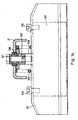
- Fig.2 shows the illustrated in schematic plan view rail vehicle 10 with the container 5 and the two spaced apart filler neck 3. Furthermore, one recognizes the arranged on the platform 9 control unit 15 with the. Housing 18.
- the power source 16 and the switching device 26 is arranged, which are each connected to the power supply to a not shown supply system of the loading station.
- the compressed air tank 17 is connected via a arranged in the duct 19 supply line 20 and arranged thereon connection lines 21, 22 and connecting members 27,28 with the two closure elements in connection.
- the power source 16 is connected for example via an electrical supply line 23 with a preferably arranged on top of the container 5 control unit 25 in connection.
- control unit 25 is connected via an electrical line 24 to the pivoting device 30 in connection.
- the closure elements of the two filler neck 3 are preferably actuated simultaneously to open and / or close the passage openings. However, a separate, pressure-controlled actuation of the closure elements is also possible.
- Figure 3 shows a portion of the partially sectioned container 5 with the attached to the container wall 7 and shown in view filler neck 3.
- the filler neck 3 comprises a welded into the container wall 7 pipe socket 40 and an insertable into the pipe socket 40 and provided with a support ring 44 insert body 45. Furthermore, one recognizes the filler neck 3 associated pivoting device 30 for the two pivotable in the horizontal plane closure elements 35 and 60.
- the outside of the filler neck 3 and arranged by means of screws 33 and spacers 32 on a first pivot arm 31 of the pivoting device 30 first closure element 35th is preferably designed as a weatherproof cover.
- a ventilation filter 34 is further arranged on the first closure element 35.
- the second closure element 60 arranged on the inside on the filler neck 3 is mounted with an intermediate member 62 on a second pivot arm 61 of the pivoting device 30.
- pivoting device 30 In the Figure 3 in view shown and mounted in a fixed to the container wall 7 head piece 85 pivoting device 30 with the individual elements will later in conjunction with Figure 6 described in detail.
- the filler neck 3 is shown in section and recognizes a portion of the container 5 with the pipe socket 40 disposed thereon and the first engaged therewith and mounted on the first pivot arm 31 first shutter member 35 and the second pivot arm 61 operatively connected second shutter member 60th the second pivot arm 61, the intermediate member 62 is arranged for mounting the closure member 60 and secured by screws 63,64.
- the first closure element 35 is attached to the spacer sleeves 32 and screws 33 on the first pivot arm 31 and operatively connected thereto.
- the first closure element 35 has an annular body 37 and a covering hood 36 arranged and fastened thereto.
- the covering hood 36 is preferably designed as a relatively flat conical roof-shaped weather protection.
- ventilation filter 34 is arranged and fixed with means not shown.
- the ring body 37 is further provided for receiving a circular ring formed as a seal 50 'with a circumferentially oriented recess 38.
- seal 50 ' can be acted upon with compressed air and is connected via at least one connection piece 55 arranged thereon and via a pipe section 27' and the connecting member 27 designed as a pipe bend to the compressed air supply line 20 (FIG. Fig.2 ) connected line 21 in conjunction.
- the in Figure 4 illustrated and fixed to the container wall 7 of the container 5 pipe socket 40 has a cylindrical cavity 41 which is formed for receiving the provided with the through hole 4 and a support ring 44 insert body 45.
- the insert body 45 is secured to the pipe socket 40 by means of screws 42 distributed on the circumference of the support ring 44.
- the insert body 45 has a through opening 4 forming cylindrical Inner wall 46 and a conically widening in the direction of the first closure element 35 formed inner wall 46 '.
- On the second closure element 60 side facing the insert body 45 is provided with a circumferentially oriented and formed to receive a seal 50 recess 49.
- seal 50 is also acted upon by compressed air and is arranged on at least one connection piece 55 arranged thereon and via a first bore 48 arranged in the insert body 45 and a second bore 47 oriented transversely thereto with the bearing ring 44 and as Screw socket formed connecting member 28 with the to the compressed air supply line 20 ( Fig.2 ) connected line 22 in conjunction.
- the first bore 48 is closed at the upper end by a screwed into the support ring 44 sealing plug 48 '.
- Figure 5 shows an in Figure 4 denoted by a circle A and shown on a larger scale and in section portion of the pipe socket 40 with the disposed in the cylindrical cavity 41 and provided with the recess 49 for the seal 50 insert body 45.
- the in Figure 5 shown in the profile cross-section and provided with a pressure chamber 54 seal 50 comprises two spaced apart side walls 52 and 52 ', a same interconnecting upper bottom 53 and a spaced therefrom lower bottom 51.
- the lower bottom 51 is in the direction of the pressure chamber 54th formed to be curved inside and pressurized the pressure chamber 54 for sealing engagement with the facing element (support ring 44 and closing element 60) elastically deformable.
- the pressure chamber 54 is connected via a connecting piece 55 penetrating bore 55 'with the provided in the insert body 45 and acted upon by compressed air bore 48 in connection.
- the arranged on the seal 50 connecting piece 55 is provided at one end with a arranged in the pressure chamber 54 contact washer 57 and at the other end by means of a screwed nut 56 at the between the bore 48 and the recess 49 of the insert body 45 provided intermediate wall 43 of the insert body 45 is attached.
- seal 50 'arranged on the first closure element 35 in the circular recess 38 and the seal 50 arranged on the second closure element 60 in the circular recess 49 are of essentially analogue design.
- Figure 6 shows as a first embodiment shown in view and partially in section pivoting device 30 which is mounted in the fixed to the container wall 7 of the container 5 head piece 85 and is operatively connected to a arranged in the container interior 6 rotary drive 65.
- the pivoting device 30 comprises a guide housing 80 arranged in the head piece 85 and designed for the coaxial mounting of an axle body 70.
- the guide housing 80 is mounted with a flange 81 on the head piece 85 and fastened by means of screws 83.
- a first bearing body 84 is arranged, which for storage and attachment of the first pivot arm 31 has a stepped portion 84 'and is held with a retaining ring 71 on the axle body 70.
- the first bearing body 84 with the first pivot arm 31 arranged thereon are operatively connected to the axle body 70 by means not shown, and are pivotable about the vertical axis Z thereof in the direction of the arrow Z '.
- In the guide housing 80 are not shown in detail and arranged in operative connection with a compression spring sealing elements, which are held at the upper end by a union nut 82 and at the lower end by a arranged on the axle 70 disc 76.
- a second bearing body 75 is arranged in a recess 86 of the head piece 85, which is held with a retaining ring 72 on the axle body 70 and for attaching the second pivot arm 61 with a stepped portion 75 'is provided.
- the manner not shown in detail via a journal 66 with the axle 70 of the pivoting device 30 operatively connected rotary drive 65 is secured by screws 67 to a support member 78.
- the retaining element 78 which is essentially U-shaped in the profile cross-section, comprises a base 77 and two sidewalls 79, 79 'integrally formed thereon and spaced apart from each other, and is fastened by means of screws 68 to the headpiece 85 provided with a side contact surface (not shown).
- the arranged on the second bearing body 75 and fixed second pivot arm 61 is about the vertical axis Z of the axle body 70 in the direction of arrow Z ', as in Figure 9 shown schematically, between the two side walls 79.79 'pivotally.
- auxiliary device 11 which comprises an attachment element 12 with arranged thereon lever 12 'and a support plate 13 with at least two pins 14 attached thereto, which provided for achieving a manual actuation of the pivoting device 30 in accordance with the first pivot arm 31 and, as in Figure 7 shown, spaced holes 8,8 'engage.
- FIG 7 is the filler neck 3 and the pipe socket 40 with the two operatively connected to the pivoting device 30 and shown in the closed position closure elements 35 and 60 shown in plan view.
- first pivot arm 31 On the pivoting device 30 of the operatively connected to the rotary drive 65 first pivot arm 31 is arranged. At the front end, the first pivot arm 31 is fastened to the cover hood 36 of the closure element 35 by means of two sections 31 'and 31 "and screws 33 which are spread apart from one another.
- the ventilation filter 34 is arranged between the two sections 31' and 31" and on the closure element 35 attached. Furthermore, one recognizes that on the first closure element 35 ( Figure 4 ) and shown schematically Pipe bend 27 with the line 21 as well as on the insert body 45 (FIG. Figure 4 ) of the pipe stub 40 arranged connecting member 28 with the line 22nd
- Fig.8 and Fig.9 is the filler neck 3 according Figure 7 shown in plan view, wherein according Figure 8 the first closing element 35 arranged on the first pivoting arm 31 of the pivoting device 30 and according to FIG Figure 9 the second closure element 60 arranged on the second pivot arm 61 of the pivoting device 30 are respectively pivoted in the open position relative to the passage opening 4 of the pipe stub 40.
- the pivoting device 30, which is operatively connected to the rotary drive 65 is designed such that the two closure elements 35 and 60 are pivotable in the double arrow direction R simultaneously and relative to the passage opening 4 of the pipe socket 40 by means of the two pivot arms 31 and 61 arranged thereon.
- the holding element 78 arranged on the head piece 85 for the rotary drive 65 is shown and it can be seen that the carrying arm 61 can be pivoted between the two side walls 79, 79 '.
- Figure 10 shows a second embodiment of the partially sectioned pivoting device 30 'for a drive 90 and it detects the attached to the container wall 7 of the container 5 head piece 85 and the guide housing 80 mounted therein for the axle body 70.
- the head piece 85 is the flange 81 and the union nut 82 provided guide housing 80, an intermediate piece 96 and a support plate 94 are arranged.
- the individual elements 80, 81 and 96, 94 are fastened to the head piece 85 by means of the screws 83.
- the first bearing body 84 is arranged, which is provided for the storage and attachment of the first pivot arm 31 with the stepped portion 84 'and held with the locking ring 71 on the axle body 70.
- the second bearing body 75 is arranged in the recess 86 of the head piece 85 and held with the retaining ring 72 on the axle body 70.
- the second pivot arm 61 is arranged and fixed.
- the two bearing bodies 84 and 75 are not shown in detail Means operatively connected to the axle body 70 and pivotable together with the respectively attached thereto pivot arms 31 and 61 about the vertical axis Z of the axle body 70 in the direction of arrow Z '.
- the drive means operatively connected to the first pivot arm 31 are arranged on the outside of the container 5 and mounted on the support plate 94.
- the drive means comprise a pneumatically or hydraulically or electrically controllable drive 90, which is arranged with a bearing block 95 on the pivoting device 30 'arranged and fixed support plate 94 and secured by means not shown.
- the drive 90 provided with an activatable piston rod 91 is operatively connected via a fork piece 92 and a pin 93 with the first pivot arm 31.
- FIG 11 is the filler neck 3 and the pipe socket 40 with the two with the pivoting device 30 'operatively connected and shown in the closed position closure elements 35 and 60 shown in plan view.
- Arranged on the pivoting device 30 ' is the first pivoting arm 31, which is operatively connected to the drive 90 and arranged with the two sections 31' and 31 "spread apart from one another and fastened to the cover 36 of the closure element 35. Between the two sections 31 'and 31" the venting filter 34 is arranged and fixed to the outer closure element 35.
- Figure 12 shows the filler neck 3 shown in plan view with the two arranged on the pivot arms 31 and 61 closure elements 35 and 60, which are shown pivoted as a result of the activated drive 90 relative to the pipe socket 40 and to the through hole 4.
- the swivel device 30 'operatively connected to the drive 90 is designed such that the two closure elements 35 and 60 are pivotable in the double-headed direction R simultaneously and relative to the through-opening 4 of the pipe socket 40 by means of the two swivel arms 31 and 61 arranged thereon.
- FIGS. 11 and 12 the pivot device 30 'shown in plan view and the support plate 94 with the bearing block 95 for the drive 90th
- Figure 12 is the axially displaceable piston rod 91 shown for the movement of the two pivot arms 31,61 and shutter members 35,60 in the end position.
- Fig. 13 shows a further embodiment of the inventive closing device, in which the outer closure elements 35 relative to the support ring 44 of the filler neck 3 in the vertical direction can be raised and lowered.
- the inner closure element 60 and the pivoting device 30 are identical to the embodiments described above.
- the filler neck 3 with the outer, liftable and liftable closure element 35 is shown in a schematic sectional view.
- the filler neck 3 comprises the pipe socket 40 welded into the container wall 7 and the insert body 45 which is provided with the bearing ring 44 and which on the side facing the first closure element 35 has a circular collar 104 arranged on the bearing ring 44 and projecting upwards having.
- the annular body 37 with the circumferentially oriented recess 38 can be seen, which is designed to receive a seal 105.
- a pneumatic cylinder 102 is arranged, the piston rod 106 projects vertically upwards.
- the upper end of the piston rod 106 is fastened to the first pivot arm 31 with a screw 101.
- the closure member 35 is operatively connected via the pneumatic cylinder 102 and the piston rod 106 with the first arm 31.
- a push-in fitting 107 is used in the FIG. 13 not shown compressed air supply of preferably designed as a short-stroke cylinder pneumatic cylinder.
- a compression spring 103 is arranged, which presses the closure element 35 away from the pivot arm 31 against the collar 104 of the support ring 44, so that the seal 105 of the closure element 35 on Collar 104 is pressed sealingly.
- FIG. 10 already described pivoting device is identical.
- the Fig. 14 shows a section of the outer closure element 35 according to the in FIG. 13 shown X direction.
- the pivot arm 31 shown in section has a pivot bearing 108 which serves to receive the screw 101, with which the piston rod 106 of the pneumatic cylinder 102 projecting vertically upwards is fastened.
- the compression spring 103 is arranged between the shutter member 35 facing the underside of the pivot arm 31 and the shutter member 35.
- the screw of the screw 101 and the spacer sleeve 109 of the pivot arm 31 is operatively connected to the closure member 35 via the piston rod 106 and the pneumatic cylinder 102.
- the pneumatic cylinder 102 shown in the example is a double-acting short-stroke pneumatic cylinder 102, which performs a switching function in cooperation with the compression spring 103.
- the piston rod 106 moves in the direction of the cylinder. Since the piston rod 106 is fixedly connected to the pivot arm 31, this movement causes a lifting of the closure element 35 against the restoring force of the compression spring 103 in the direction of the pivot arm 31.
- the closure member 35 away from the pivot arm 31 in the direction of Auflagerings 4. That is, via a compressed air control, not shown, the closure element 35 between an upper and lower position relative to the circular collar 104 of the support ring 44 can be raised and lowered.
- the outer closure element 35 When opening and closing the locking device according to FIG. 13 and 14 the outer closure element 35 is raised by means of the compressed air control. As a result, the seal 105 is no longer on the collar 104. Further, the pressure chamber 54 provided for sealing the lower shutter member 60 becomes 54 depressurizes the seal 50 whereby now the two closure elements 35, 60 are pivotable horizontally by means of the pivoting device 30 relative to the passage opening 4 of the filler neck 3. For closing the passage opening 4, the closure elements 35, 60 are positioned correspondingly over the passage opening 4 in the closed position. By venting the pneumatic cylinder 102, the outer closure member 35 is lowered. The compression spring 103 presses the closure element 35 down and thus also the seal 105 against the collar 104 of the support ring 44. Thus, the passage opening 4 is sealed from the outside. The pressure chamber 54 of the seal 50 is pressurized, whereby the lower closure member 60 closes the passage opening from the inside tight.
- seal 105 is preferably formed as a square square sealing cord and arranged interchangeable in the circular recess 38.
Landscapes
- Engineering & Computer Science (AREA)
- Mechanical Engineering (AREA)
- Health & Medical Sciences (AREA)
- Public Health (AREA)
- Transportation (AREA)
- Pressure Vessels And Lids Thereof (AREA)
- Closures For Containers (AREA)
- Filling Or Emptying Of Bunkers, Hoppers, And Tanks (AREA)
- Basic Packing Technique (AREA)
Abstract
Description
Die Erfindung bezieht sich auf eine Schliesseinrichtung für an einem Behälter A angeordnete Einfüllstutzen, gemäß dem Oberbegriff von Anspruch 1, insbesondere für einen auf einem Schienen- oder Strassenfahrzeug angeordneten und zum Beladen mit pulverförmigen oder körnigen Schüttgütern ausgebildeten Behälter.The invention relates to a closing device for arranged on a container A filler neck, according to the preamble of
Aus der Druckschrift
Der Erfindung liegt die Aufgabe zugrunde, für den an einem Behälter der eingangs genannten Gattung angeordneten Einfüllstutzen eine zur Betätigung der aussenseitig sowie innenseitig angeordneten Verschlusselemente ausgebildete Schliesseinrichtung zu schaffen, welche die Nachteile des erwähnten Standes der Technik überwindet und mit geeigneten Mitteln eine in Bezug auf den Einfüllstutzen orientierte und gesteuerte Relativbewegung der beiden Verschlusselemente sowie ein exaktes Abdichten derselben in Bezug auf den Einfüllstutzen gewährleistet.The invention has for its object to provide for the arranged on a container of the type mentioned filler neck for operating the outside and inside arranged closure elements designed closing device, which overcomes the disadvantages of the mentioned prior art and with suitable means with respect to the Filler oriented and controlled relative movement of the two closure elements and an exact sealing of the same with respect to the filler neck ensures.
Die erfindungsgemässe Schliesseinrichtung, ist dadurch gekennzeichnet, dass mindestens eine Dichtung eine in Umfangrichtung orientierte und mit mindestens einem Anschlussglied sowie einer Versorgungsleitung in Verbindung stehende Druckkammer aufweist, welche in der Schliess-Stellung druckbeaufschlagbar und für die Offen-Stellung der Verschlusselemente druckentlastbar ist.The closing device according to the invention is characterized in that at least one seal has a pressure chamber oriented in the circumferential direction and in communication with at least one connecting member and a supply line, which can be pressurized in the closed position and pressure-relieved for the open position of the closing elements.
Mit der erfindungsgemässen Schliesseinrichtung wird in vorteilhafter Weise eine ansteuerbare und weitgehend automatische Schwenkbewegung der beiden Verschlusselemente sowie mittels der druckbeaufschlagbaren Dichtungen bzw. Absenken und Andrücken des äusseren Verschlusselementes mittels einer Druckfeder an eine Mannlochdichtung ein exaktes Abdichten und somit eine weitgehende Automatisierung des Beladevorgangs erreicht. Die Schwenkbewegung der beiden Verschlusselemente kann auch durch Aussenden eines die Schliesseinrichtung aktivierenden Signals, beispielsweise von einem ortsungebundenen Sender erfolgen.With the closing device according to the invention a controllable and largely automatic pivoting movement of the two closure elements and by means of the pressurizable seals or lowering and pressing of the outer closure element by means of a compression spring to a manhole seal an exact sealing and thus a high degree of automation of the loading process is achieved. The pivoting movement of the two closure elements can also by sending a the Closing device activating signal, for example, done by a non-stationary transmitter.
Bei einer weiteren Ausgestaltung sind die Verschlusselemente derart an der vertikalen Achse angeordnet und damit wirkverbunden, dass diese simultan und relativ zu der Durchgangsöffnung des Einfüllstutzens schwenkbar sind.In a further embodiment, the closure elements are arranged on the vertical axis and operatively connected so that they are simultaneously and pivotally relative to the passage opening of the filler neck.
Es ist weiterhin vorteilhaft, dass die in dem Verschlusselement beziehungsweise in dem Einsatzkörper des Einfüllstutzens angeordneten Dichtungen in den entsprechend ausgebildeten Ausnehmungen auswechselbar eingesetzt und durch mindestens eine am Umfang der Dichtung angeordneten Schraubverbindung befestigt sind.It is furthermore advantageous that the seals arranged in the closure element or in the insert body of the filler neck are exchangeably inserted in the correspondingly formed recesses and fastened by at least one screw connection arranged on the circumference of the seal.
Weitere Merkmale, Vorteile sowie zweckmässige weitere Ausgestaltungen der Erfindung ergeben sich aus der nachstehenden Beschreibung und den Patentansprüchen.Other features, advantages and expedient further embodiments of the invention will become apparent from the following description and the claims.
Ausführungsbeispiele der Erfindung werden nachstehend anhand der Zeichnung beschrieben. Es zeigt:
- Fig.1
- ein in schematischer Ansicht dargestelltes und dem Silobehälter einer Schüttgut-Verladestation zugeführtes Schienenfahrzeug mit einem darauf angeordneten Behälter;
- Fig.2
- das in Draufsicht dargestellte Fahrzeug gemäss
Fig.1 mit dem Behälter und zwei daran im Abstand zueinander angeordneten Einfüllstutzen; - Fig.3
- den gemäss der Linie III-III in
Fig.1 teilweise im Schnitt dargestellten Behälter mit dem Einfüllstutzen und einer daran angeordneten Schwenkvorrichtung für zwei relativ zu dem Einfüllstutzen bewegbare Verschlusselemente; - Fig.4
- den im Schnitt dargestellten Einfüllstutzen gemäss
Fig.3 mit dem jeweils aussenseitig und innenseitig daran angeordneten Verschlusselement; - Fig.5
- ein in
Fig.4 durch einen Kreis A bezeichnetes und in grösserem Massstab dargestelltes Teilstück des Einfüllstutzens mit daran angeordneter Dichtung; - Fig.6
- ein in grösserem Massstab dargestelltes erstes Ausführungsbeispiel der teilweise im Schnitt dargestellten Schwenkvorrichtung für die Verschlusselemente;
- Fig.7
- den in schematischer Draufsicht dargestellten Einfüllstutzen mit der Schwenkvorrichtung und den beiden in geschlossener Stellung dargestellten Verschlusselementen;
- Fig.8
- den Einfüllstutzen gemäss
Fig.7 mit dem relativ dazu verschwenkten äusseren Verschlusselement; - Fig.9
- den Einfüllstutzen gemäss
Fig.7 mit dem relativ dazu verschwenkten inneren Verschlusselement; - Fig.10
- ein zweites Ausführungsbeispiel der aussenseitig an dem Behälter angeordneten Schwenkvorrichtung für die beiden Verschlusselemente;
- Fig.11
- den in schematischer Draufsicht dargestellten Einfüllstutzen gemäss
Fig.10 mit den in geschlossener Stellung dargestellten Verschlusselementen; - Fig.12
- den Einfüllstutzen gemäss
Fig.10 mit den beiden relativ dazu in die Offenstellung verschwenkten Verschlusselementen; - Fig.13
- eine Ausführungsvariante mit einem äusseren, anhebbaren Verschlusselement in einer schematischen Schnittzeichnung; und
- Fig.14
- einen Ausschnitt des äusseren im Schnitt
dargestellten Verschlusselementes 35 in der inFigur 13
- Fig.1
- a schematically illustrated and fed to the silo of a bulk material loading station rail vehicle with a container disposed thereon;
- Fig.2
- the vehicle shown in plan view
Fig.1 with the container and two spaced therefrom filler neck; - Figure 3
- according to the line III-III in
Fig.1 partly in section container with the filler neck and a pivoting device arranged thereon for two relative to the filler neck movable closure elements; - Figure 4
- the filler neck shown in section according to
Figure 3 with the closure element respectively arranged on the outside and inside thereof; - Figure 5
- a in
Figure 4 designated by a circle A and shown on a larger scale portion of the filler neck with seal arranged thereon; - Figure 6
- a shown on a larger scale first embodiment of the partially shown in section pivoting device for the closure elements;
- Figure 7
- the filler neck shown in schematic plan view with the pivoting device and the two closure elements shown in the closed position;
- Figure 8
- according to the filler neck
Figure 7 with the outer closure element pivoted relative thereto; - Figure 9
- according to the filler neck
Figure 7 with the inner closure element pivoted relative thereto; - Figure 10
- a second embodiment of the outside of the container arranged pivoting device for the two closure elements;
- Figure 11
- the filler neck shown in schematic plan view
Figure 10 with the closure elements shown in the closed position; - Figure 12
- according to the filler neck
Figure 10 with the two shutter elements pivoted relative to the open position; - Figure 13
- a variant with an outer, liftable closure element in a schematic sectional view; and
- Figure 14
- a section of the
outer closure element 35 shown in section in the inFIG. 13 shown X direction.
Der in
zum Einführen eines an dem Silobehälter 1 angeordneten Verladekopfes 2 ausgebildet sind. Der einzelne Einfüllstutzen 3 steht über eine in
in Bezug auf den Behälterinnenraum 6 beziehungsweise auf die Behälterwand 7 aussenseitig sowie ein innenseitig angeordnetes und in
for introducing a arranged on the
with respect to the
An dem einen Ende des Schienenfahrzeuges 10 ist auf der Plattform 9 eine schematisch dargestellte und mit einem Druckluftbehälter 17, einer Energiequelle 16 sowie einer betätigbaren elektrischen Schalteinrichtung 26 versehene Bedienungseinheit 15 angeordnet. Der Druckluftbehälter 17 und die Energiequelle 16 sowie die Schalteinrichtung 26 sind in einem Gehäuse 18 angeordnet und werden jeweils über einen nicht dargestellten Netzanschluss mit Druckluft beziehungsweise elektrischer Energie versorgt. Als Energiequelle dient beispielsweise eine Druckluftflasche mit einem Volumen von 50 l und 200 bar. An dem abschliessbar ausgebildeten Gehäuse 18 ist weiterhin ein bis oben auf den Behälter 5 reichender Leitungskanal 19 angeordnet. In dem Leitungskanal 19 sind einerseits mit dem Druckluftbehälter 17, der Energiequelle 16 und der Schalteinrichtung 26 und andererseits mit dem Einfüllstutzen 3 sowie mit der Schwenkvorrichtung 30 in Verbindung stehende pneumatische und elektrische Versorgungsleitungen angeordnet.At the one end of the
In
Das erste Verschlusselement 35 ist mit den Distanzbuchsen 32 und Schrauben 33 an dem ersten Schwenkarm 31 befestigt und damit wirkverbunden. Das erste Verschlusselement 35 hat einen Ringkörper 37 sowie eine daran angeordnete und befestigte Abdeckhaube 36. Die Abdeckhaube 36 ist vorzugsweise als relativ flacher kegeldachförmiger Wetterschutz ausgebildet. An der Abdeckhaube 36 ist der mit einem Stutzen 34' in die Durchgangsöffnung 4 ragende Belüftungsfilter 34 angeordnet und mit nicht dargestellten Mitteln befestigt. Der Ringkörper 37 ist weiterhin zur Aufnahme einer als zirkulärer Ring ausgebildeten Dichtung 50' mit einer in Umfangsrichtung orientierten Ausnehmung 38 versehen. Die in
Der in
Die in
An dieser Stelle wird darauf hingewiesen, dass die an dem ersten Verschlusselement 35 in der zirkulären Ausnehmung 38 angeordnete Dichtung 50' sowie die an dem zweiten Verschlusselement 60 in der zirkulären Ausnehmung 49 angeordnete Dichtung 50 im wesentlichen analog ausgebildet sind.It should be noted at this point that the seal 50 'arranged on the
An dem einen Ende des Achskörpers 70 ist ein erster Lagerkörper 84 angeordnet, welcher zur Lagerung und Befestigung des ersten Schwenkarms 31 ein abgesetztes Teilstück 84' aufweist und mit einem Sicherungsring 71 an dem Achskörper 70 gehalten ist. Der erste Lagerkörper 84 mit dem daran angeordneten ersten Schwenkarm 31 sind mit nicht dargestellten Mitteln mit dem Achskörper 70 wirkverbunden und miteinander um die vertikale Achse Z desselben in Pfeilrichtung Z' schwenkbar. In dem Führungsgehäuse 80 sind nicht näher dargestellte und mit einer Druckfeder in Wirkverbindung stehende Dichtelemente angeordnet, welche am oberen Ende durch eine Überwurfmutter 82 und am unteren Ende durch eine am Achskörper 70 angeordnete Scheibe 76 gehalten sind. An dem unteren Ende des Achskörpers 70 ist in einer Ausnehmung 86 des Kopfstücks 85 ein zweiter Lagerkörper 75 angeordnet, welcher mit einem Sicherungsring 72 an dem Achskörper 70 gehalten und zur Befestigung des zweiten Schwenkarms 61 mit einem abgesetzt ausgebildeten Teilstück 75' versehen ist.At the one end of the
Der in nicht näher dargestellter Weise über einen Achszapfen 66 mit dem Achskörper 70 der Schwenkvorrichtung 30 wirkverbundene Drehantrieb 65 ist mittels Schrauben 67 an einem Halteelement 78 befestigt. Das im Profilquerschnitt im wesentlichen U-förmig ausgebildete Halteelement 78 umfasst einen Boden 77 sowie zwei seitlich daran angeformte und im Abstand zueinander angeordnete Seitenwände 79,79' und ist mittels Schrauben 68 an dem mit einer nicht näher dargestellten seitlichen Anlagefläche versehenen Kopfstück 85 befestigt. Der an dem zweiten Lagerkörper 75 angeordnete und befestigte zweite Schwenkarm 61 ist um die vertikale Achse Z des Achskörpers 70 gemäss Pfeilrichtung Z', wie in
An dieser Stelle wird darauf hingewiesen, dass die um die vertikale Achse Z in Pfeilrichtung Z' orientierte Bewegung des Achskörpers 70 sowie die damit wirkverbundenen Elemente mittels des ansteuerbaren Drehantriebs 65 erfolgt. Bei etwaigen Störungen kann die Drehbewegung der Elemente auch mittels einer in
In
In
An dem einen Ende des Achskörpers 70 ist der erste Lagerkörper 84 angeordnet, welcher zur Lagerung und Befestigung des ersten Schwenkarms 31 mit dem abgesetzten Teilstück 84' versehen und mit dem Sicherungsring 71 an dem Achskörper 70 gehalten ist. An dem anderen Ende des Achskörpers 70 ist in der Ausnehmung 86 des Kopfstücks 85 der zweite Lagerkörper 75 angeordnet und mit dem Sicherungsring 72 an dem Achskörper 70 gehalten. An dem abgesetzten Teilstück 75' des Lagerkörpers 70 ist der zweite Schwenkarm 61 angeordnet und befestigt. Die beiden Lagerkörper 84 und 75 sind mit nicht näher dargestellten Mitteln mit dem Achskörper 70 wirkverbunden und zusammen mit den jeweils daran befestigten Schwenkarmen 31 und 61 um die vertikale Achse Z des Achskörpers 70 in Pfeilrichtung Z' schwenkbar.At the one end of the
Abweichend von dem ersten Ausführungsbeispiel gemäss
In
Weiterhin erkennt man in
In der
Die
Beim Öffnen und Schliessen der Schliesseinrichtung gemäss
Abweichend von dem in
Claims (16)
- A closing device for a container (5) in particular situated on a rail or road vehicle (10) and implemented for loading with powdered or granular bulk goods, the closing device comprising a filler neck (3), which is provided with a through opening (4) and is mounted to the container and connected to the container interior (6), the closing device further comprising a pivot device (30), as well as a first closure element (35) and a second closure element (60) for exterior and interior closing or opening of the through opening (4), and wherein the closure elements (35, 60) are pivotable horizontally around a shared vertical axis (Z) of the pivot device (30), which is operationally linked to activatable drive means (65, 90), in relation to the through opening (4) of the filler neck (3), and a seal (50. 50') is situated at one end of the filler neck or at the corresponding closing element, characterized in that at least one seal having a pressure chamber (54), which is oriented around the circumference and is connected to at least one connection element (27, 28) and a supply line (20), which may be impinged with pressure in the closed position and may be relieved of pressure for the open position of the closure elements (35, 60).
- The closing device according to Claim 1, characterized by a control unit (25), situated on the container (5) and activatable by a location-independent transmitter by transmitting a signal, which is operationally linked to the pivot device (30) for pivoting the two closure elements (35, 60) around the axis (Z).
- The closing device according to Claim 1 or 2, characterized by two pivot arms (31, 61), situated at a distance to one another on an axle body (70) of the pivot device (30) and each implemented for mounting the two closure elements (35, 60), which are simultaneously pivotable around the vertical axis (Z) of the axle body (70) by a rotational drive (65) situated in the container interior (6).
- The closing device according to Claim 1 or 2, characterized in that the two pivot arms (31, 61), each implemented for mounting two closing elements (35, 60), are mounted at a distance to each other on an axle body (70) of the pivot device (30) and are pivotable simultaneously around the vertical axis (Z) of the axle body (70) situated thereon by a drive (90) situated externally on the container (5)
- The closing device according to Claim 4, characterized in that the drive (90) is implemented as a pressure cylinder which may be impinged and relieved.
- The closing device according to one of Claims 1 through 5, characterized in that the filler neck (3) has a pipe neck (40) for coaxially receiving an insert body (45), which, on the side facing toward the first closure element (35), has a support ring (44) for a first seal (50', 105), and, on the side facing toward the second closure element (60), has a recess (49) oriented around the circumference for the second seal (50), which is provided with a circular pressure chamber (54).
- The closing device according to Claim 6, characterized in that the first closure element (35) comprises a cover hood (36), implemented as a weather guard shaped like a conical roof, and a ring body (37), which, on the side facing toward the support ring (44), has a recess (38) oriented around the circumference for the first seal (50', 105), which is either provided with a circular pressure chamber (54) or is implemented as a square four-edge sealing cord.
- The closing device according to Claim 6 or 7, characterized in that the seals (50, 50') provided with a pressure chamber (54) have multiple connection nozzles (55) situated distributed apart from one another around the circumference, using which the seals (50, 50') are fastened to the ring body (37) of the closure element (35) and/or to the insert body (45) of the pipe neck (40).
- The closing device according to Claim 6 or 7, characterized in that the seals (50, 50', 105) are situated replaceably in the recess (38) of the ring body (37) and/or in the recess (49) of the insert body (45).
- The closing device according to Claim 6 or 7, characterized in that the seals (50, 50') provided with a pressure chamber (54) are connected via multiple connection elements (27, 28), which are situated distributed apart from one another around the circumference, to the supply line (20).
- The closing device according to Claims 6 and 7, characterized in that the first closure element (35) comprises a cover hood (36), implemented as a weather guard shaped like a conical roof, and means (102, 103) are provided for vertically raising and lowering the closure element (35), the filler neck (3) having the pipe neck (40) for coaxially receiving the insert body (45), which, on the side facing toward the first closure element (35) has a collar (104), situated on the support ring (44) and projecting upward, for the first seal (105) situated in the recess (38) oriented around the circumference, and, on the side facing toward the second closure element (60), has the recess (49) oriented around the circumference for the second seal (50) provided with a circular pressure chamber (54).
- The closing device according to Claim 11, characterized in that the closure element (35) may be pressed against the collar (104) of the support ring (44) by the restoring force of a compression spring (103), and may be raised in relation to the support ring (44) in the direction of the pivot arm (31) using a short-stroke pneumatic cylinder (102).
- The closing device according to Claim 11, characterized in that a second seal (50) situated in the recess (49) of the insert body (45) has multiple connection nozzles (55), which are situated distributed apart from one another around the circumference and are connected to the pressure chamber (54), using which the seal (50) is fastened to the insert body (45) of the pipe neck (40).
- The closing device according to In 12 or 13, characterized in that the second seal (50) is situated replaceably in the recess (49) of the insert body (45)
- The closing device according to Claims 12 and 13, characterized in that the second seal (50) is connected to the supply line (20) via multiple connection elements (27) situated distributed apart from one another around the circumference.
- The closing device according to Claim 11, characterized in that the first seal (105) situated in the recess (38) of the closure element (45) is a circular sealing cord implemented as square in profile cross-section.
Applications Claiming Priority (3)
| Application Number | Priority Date | Filing Date | Title |
|---|---|---|---|
| CH13752005 | 2005-08-23 | ||
| CH19082005 | 2005-12-01 | ||
| PCT/CH2006/000430 WO2007022652A2 (en) | 2005-08-23 | 2006-08-14 | Closing device for a filler neck disposed on a container |
Publications (2)
| Publication Number | Publication Date |
|---|---|
| EP1917162A2 EP1917162A2 (en) | 2008-05-07 |
| EP1917162B1 true EP1917162B1 (en) | 2010-04-07 |
Family
ID=37402678
Family Applications (1)
| Application Number | Title | Priority Date | Filing Date |
|---|---|---|---|
| EP06761281A Not-in-force EP1917162B1 (en) | 2005-08-23 | 2006-08-14 | Closing device for a filler neck disposed on a container |
Country Status (6)
| Country | Link |
|---|---|
| US (1) | US8127959B2 (en) |
| EP (1) | EP1917162B1 (en) |
| AT (1) | ATE463386T1 (en) |
| CA (1) | CA2619757C (en) |
| DE (1) | DE502006006650D1 (en) |
| WO (1) | WO2007022652A2 (en) |
Cited By (1)
| Publication number | Priority date | Publication date | Assignee | Title |
|---|---|---|---|---|
| EP3738904A2 (en) | 2019-04-26 | 2020-11-18 | Feldbinder Spezialfahrzeugwerke GmbH | Dome cover for closing an opening of a container, container and vehicle therewith |
Families Citing this family (15)
| Publication number | Priority date | Publication date | Assignee | Title |
|---|---|---|---|---|
| US7484322B2 (en) | 2004-10-22 | 2009-02-03 | Mclaughlin Group, Inc. | Digging and backfill apparatus |
| US7837050B2 (en) * | 2006-10-06 | 2010-11-23 | McLaughlin Group, Inc | Collection tank |
| US20080244859A1 (en) * | 2007-04-03 | 2008-10-09 | Charles Robert Maybury | Vacuum system with improved mobility |
| US20140183194A1 (en) * | 2013-01-01 | 2014-07-03 | Steven Richard Ambriz | Closure safety interlock with lockout plate for pressure vessel |
| US20150137501A1 (en) * | 2013-07-02 | 2015-05-21 | Mac Trailer Manufacturing, Inc. | Trailer and method of manufacturing same |
| US9308852B2 (en) * | 2013-07-02 | 2016-04-12 | Mac Trailer Manufacturing, Inc. | Method of manufacturing a trailer |
| US9789916B1 (en) | 2013-10-16 | 2017-10-17 | Racehorse Investments, L.L.C. | Pneumatic tank trailer |
| US9616799B1 (en) | 2013-10-16 | 2017-04-11 | Racehorse Investments, L.L.C. | Pneumatic tank trailer |
| US9758083B1 (en) | 2013-10-16 | 2017-09-12 | Racehorse Investments, L.L.C. | Pneumatic tank trailer |
| CN104728440B (en) * | 2015-04-01 | 2017-01-11 | 中国石油集团渤海钻探工程有限公司 | High-pressure quick-opening manhole device |
| CN108584195A (en) * | 2017-12-08 | 2018-09-28 | 浙江山丰智能科技股份有限公司 | A kind of automatic open-close manhole cover and its application method |
| CN110482045B (en) * | 2019-09-03 | 2021-08-06 | 扬州北方空压机有限公司 | Manhole cover capable of being sealed quickly |
| US11801785B2 (en) | 2020-06-17 | 2023-10-31 | Vermeer Manufacturing Company | Vacuum excavator tank and door system |
| CN112193641A (en) * | 2020-10-21 | 2021-01-08 | 河北光德罐阀科技有限公司 | Automatic manhole device for tank body |
| CN113800136B (en) * | 2021-08-28 | 2023-09-12 | 安徽江淮扬天汽车股份有限公司 | Tank device of powder tank truck |
Family Cites Families (11)
| Publication number | Priority date | Publication date | Assignee | Title |
|---|---|---|---|---|
| US2818992A (en) * | 1955-08-15 | 1958-01-07 | Giles C Ekola | Releasable cover and seal for containers |
| US3178779A (en) * | 1962-06-28 | 1965-04-20 | North American Aviation Inc | Multi-cell inflatable seal |
| US3240038A (en) * | 1963-09-23 | 1966-03-15 | Ametek Inc | Inflatable washing machine door seal |
| US3325042A (en) * | 1964-11-04 | 1967-06-13 | American Sterilizer Co | Inflatable seal |
| GB1345290A (en) * | 1971-12-23 | 1974-01-30 | Dunlop Ltd | Inflatable seals |
| NL8303867A (en) * | 1983-11-10 | 1985-06-03 | Goudsche Machinefabriek Bv | FILL COVER CONSTRUCTION FOR A STEAM PACKING DEVICE. |
| IT1247672B (en) * | 1990-01-25 | 1994-12-28 | Olimpio Stocchiero | COVER WITH SEALING DEVICE FOR CONTAINERS |
| US6095365A (en) * | 1998-08-24 | 2000-08-01 | The Heil Company | Pivoting hatch cover assembly |
| EP1274604A1 (en) * | 2001-03-19 | 2003-01-15 | Stag AG | Closing device for a filler neck disposed on a container |
| US8070009B2 (en) * | 2004-01-23 | 2011-12-06 | Rmc Engineering Co., Inc. | Remotely activated tank hatch system |
| US7837050B2 (en) * | 2006-10-06 | 2010-11-23 | McLaughlin Group, Inc | Collection tank |
-
2006
- 2006-08-14 CA CA002619757A patent/CA2619757C/en active Active
- 2006-08-14 US US12/064,709 patent/US8127959B2/en not_active Expired - Fee Related
- 2006-08-14 DE DE502006006650T patent/DE502006006650D1/en active Active
- 2006-08-14 EP EP06761281A patent/EP1917162B1/en not_active Not-in-force
- 2006-08-14 WO PCT/CH2006/000430 patent/WO2007022652A2/en active Application Filing
- 2006-08-14 AT AT06761281T patent/ATE463386T1/en active
Cited By (2)
| Publication number | Priority date | Publication date | Assignee | Title |
|---|---|---|---|---|
| EP3738904A2 (en) | 2019-04-26 | 2020-11-18 | Feldbinder Spezialfahrzeugwerke GmbH | Dome cover for closing an opening of a container, container and vehicle therewith |
| EP3738904A3 (en) * | 2019-04-26 | 2020-12-30 | Feldbinder Spezialfahrzeugwerke GmbH | Dome cover for closing an opening of a container, container and vehicle therewith |
Also Published As
| Publication number | Publication date |
|---|---|
| ATE463386T1 (en) | 2010-04-15 |
| US20080190929A1 (en) | 2008-08-14 |
| CA2619757C (en) | 2010-02-02 |
| US8127959B2 (en) | 2012-03-06 |
| CA2619757A1 (en) | 2007-03-01 |
| DE502006006650D1 (en) | 2010-05-20 |
| WO2007022652A3 (en) | 2007-04-19 |
| WO2007022652A2 (en) | 2007-03-01 |
| EP1917162A2 (en) | 2008-05-07 |
| WO2007022652A9 (en) | 2008-02-28 |
Similar Documents
| Publication | Publication Date | Title |
|---|---|---|
| EP1917162B1 (en) | Closing device for a filler neck disposed on a container | |
| EP2329153A1 (en) | Apparatus driven by compressed air and equipped with dual piston function for use in body construction in the automotive industry | |
| DE4237790C2 (en) | Self-closing container closure | |
| DE102006016177A1 (en) | Vehicle body with active hood | |
| DE4404315C2 (en) | Feeding device for a pressurized shaft furnace | |
| DE3716436C2 (en) | ||
| EP0038978B1 (en) | Pressure control device with indicator for at least two vessels jointly connected under pressure | |
| EP3529526A1 (en) | Filling device for filling a fluid reservoir, and device for coupling the filling device to a filling duct of the fluid reservoir | |
| DE4441551C1 (en) | Device for lifting and emptying containers for recycling materials | |
| DE3721672C2 (en) | ||
| EP2036836B1 (en) | Cover device to close an opening in a container | |
| DE19812384A1 (en) | Fuel tank cap | |
| EP1493688B1 (en) | Refuse receptacle | |
| DE3533108C2 (en) | ||
| EP1847447B1 (en) | Posts for the loading aperture of a vehicle superstructure | |
| DE19908252A1 (en) | Car body structure with window body panel and windscreen/tailgate wiper unit forming modular component block | |
| DE4005984C2 (en) | ||
| DE2559390B2 (en) | COAL FILLER | |
| DE19931746B4 (en) | trailer hitch | |
| DE3645015C2 (en) | ||
| DE10008515A1 (en) | Actuator for motorized vehicle door has door handle with decoupling position in which it decouples drive device from door or vehicle body and opens door lock if closed | |
| EP0976670A1 (en) | Apparatus for the pneumatic conveyance of pulverized or granulated matter | |
| DE102011002551A1 (en) | Discharging device for discharging silo container in articulated lorry for transporting powder, grain or pellet-like bulk goods, has opening closed and opened by closing unit, such that goods are discharged from discharge part via opening | |
| DE202010007631U1 (en) | Outlet device for bulk material | |
| DE2830147C2 (en) | Reducing valve |
Legal Events
| Date | Code | Title | Description |
|---|---|---|---|
| PUAI | Public reference made under article 153(3) epc to a published international application that has entered the european phase |
Free format text: ORIGINAL CODE: 0009012 |
|
| 17P | Request for examination filed |
Effective date: 20080311 |
|
| AK | Designated contracting states |
Kind code of ref document: A2 Designated state(s): AT BE BG CH CY CZ DE DK EE ES FI FR GB GR HU IE IS IT LI LT LU LV MC NL PL PT RO SE SI SK TR |
|
| AX | Request for extension of the european patent |
Extension state: AL BA HR MK RS |
|
| GRAP | Despatch of communication of intention to grant a patent |
Free format text: ORIGINAL CODE: EPIDOSNIGR1 |
|
| DAX | Request for extension of the european patent (deleted) | ||
| GRAS | Grant fee paid |
Free format text: ORIGINAL CODE: EPIDOSNIGR3 |
|
| GRAA | (expected) grant |
Free format text: ORIGINAL CODE: 0009210 |
|
| AK | Designated contracting states |
Kind code of ref document: B1 Designated state(s): AT BE BG CH CY CZ DE DK EE ES FI FR GB GR HU IE IS IT LI LT LU LV MC NL PL PT RO SE SI SK TR |
|
| REG | Reference to a national code |
Ref country code: GB Ref legal event code: FG4D Free format text: NOT ENGLISH |
|
| REG | Reference to a national code |
Ref country code: CH Ref legal event code: EP |
|
| REG | Reference to a national code |
Ref country code: IE Ref legal event code: FG4D Free format text: LANGUAGE OF EP DOCUMENT: GERMAN |
|
| REF | Corresponds to: |
Ref document number: 502006006650 Country of ref document: DE Date of ref document: 20100520 Kind code of ref document: P |
|
| REG | Reference to a national code |
Ref country code: CH Ref legal event code: NV Representative=s name: SPIERENBURG & PARTNER AG, PATENT- UND MARKENANWAEL |
|
| REG | Reference to a national code |
Ref country code: NL Ref legal event code: T3 |
|
| PG25 | Lapsed in a contracting state [announced via postgrant information from national office to epo] |
Ref country code: SI Free format text: LAPSE BECAUSE OF FAILURE TO SUBMIT A TRANSLATION OF THE DESCRIPTION OR TO PAY THE FEE WITHIN THE PRESCRIBED TIME-LIMIT Effective date: 20100407 |
|
| LTIE | Lt: invalidation of european patent or patent extension |
Effective date: 20100407 |
|
| REG | Reference to a national code |
Ref country code: IE Ref legal event code: FD4D |
|
| PG25 | Lapsed in a contracting state [announced via postgrant information from national office to epo] |
Ref country code: SE Free format text: LAPSE BECAUSE OF FAILURE TO SUBMIT A TRANSLATION OF THE DESCRIPTION OR TO PAY THE FEE WITHIN THE PRESCRIBED TIME-LIMIT Effective date: 20100407 Ref country code: ES Free format text: LAPSE BECAUSE OF FAILURE TO SUBMIT A TRANSLATION OF THE DESCRIPTION OR TO PAY THE FEE WITHIN THE PRESCRIBED TIME-LIMIT Effective date: 20100718 Ref country code: LT Free format text: LAPSE BECAUSE OF FAILURE TO SUBMIT A TRANSLATION OF THE DESCRIPTION OR TO PAY THE FEE WITHIN THE PRESCRIBED TIME-LIMIT Effective date: 20100407 |
|
| PG25 | Lapsed in a contracting state [announced via postgrant information from national office to epo] |
Ref country code: FI Free format text: LAPSE BECAUSE OF FAILURE TO SUBMIT A TRANSLATION OF THE DESCRIPTION OR TO PAY THE FEE WITHIN THE PRESCRIBED TIME-LIMIT Effective date: 20100407 Ref country code: IS Free format text: LAPSE BECAUSE OF FAILURE TO SUBMIT A TRANSLATION OF THE DESCRIPTION OR TO PAY THE FEE WITHIN THE PRESCRIBED TIME-LIMIT Effective date: 20100807 Ref country code: LV Free format text: LAPSE BECAUSE OF FAILURE TO SUBMIT A TRANSLATION OF THE DESCRIPTION OR TO PAY THE FEE WITHIN THE PRESCRIBED TIME-LIMIT Effective date: 20100407 |
|
| PG25 | Lapsed in a contracting state [announced via postgrant information from national office to epo] |
Ref country code: PL Free format text: LAPSE BECAUSE OF FAILURE TO SUBMIT A TRANSLATION OF THE DESCRIPTION OR TO PAY THE FEE WITHIN THE PRESCRIBED TIME-LIMIT Effective date: 20100407 Ref country code: CY Free format text: LAPSE BECAUSE OF FAILURE TO SUBMIT A TRANSLATION OF THE DESCRIPTION OR TO PAY THE FEE WITHIN THE PRESCRIBED TIME-LIMIT Effective date: 20100526 Ref country code: GR Free format text: LAPSE BECAUSE OF FAILURE TO SUBMIT A TRANSLATION OF THE DESCRIPTION OR TO PAY THE FEE WITHIN THE PRESCRIBED TIME-LIMIT Effective date: 20100708 |
|
| PG25 | Lapsed in a contracting state [announced via postgrant information from national office to epo] |
Ref country code: PT Free format text: LAPSE BECAUSE OF FAILURE TO SUBMIT A TRANSLATION OF THE DESCRIPTION OR TO PAY THE FEE WITHIN THE PRESCRIBED TIME-LIMIT Effective date: 20100809 Ref country code: DK Free format text: LAPSE BECAUSE OF FAILURE TO SUBMIT A TRANSLATION OF THE DESCRIPTION OR TO PAY THE FEE WITHIN THE PRESCRIBED TIME-LIMIT Effective date: 20100407 Ref country code: EE Free format text: LAPSE BECAUSE OF FAILURE TO SUBMIT A TRANSLATION OF THE DESCRIPTION OR TO PAY THE FEE WITHIN THE PRESCRIBED TIME-LIMIT Effective date: 20100407 Ref country code: IE Free format text: LAPSE BECAUSE OF FAILURE TO SUBMIT A TRANSLATION OF THE DESCRIPTION OR TO PAY THE FEE WITHIN THE PRESCRIBED TIME-LIMIT Effective date: 20100407 |
|
| PLBE | No opposition filed within time limit |
Free format text: ORIGINAL CODE: 0009261 |
|
| STAA | Information on the status of an ep patent application or granted ep patent |
Free format text: STATUS: NO OPPOSITION FILED WITHIN TIME LIMIT |
|
| PG25 | Lapsed in a contracting state [announced via postgrant information from national office to epo] |
Ref country code: SK Free format text: LAPSE BECAUSE OF FAILURE TO SUBMIT A TRANSLATION OF THE DESCRIPTION OR TO PAY THE FEE WITHIN THE PRESCRIBED TIME-LIMIT Effective date: 20100407 Ref country code: RO Free format text: LAPSE BECAUSE OF FAILURE TO SUBMIT A TRANSLATION OF THE DESCRIPTION OR TO PAY THE FEE WITHIN THE PRESCRIBED TIME-LIMIT Effective date: 20100407 Ref country code: CZ Free format text: LAPSE BECAUSE OF FAILURE TO SUBMIT A TRANSLATION OF THE DESCRIPTION OR TO PAY THE FEE WITHIN THE PRESCRIBED TIME-LIMIT Effective date: 20100407 |
|
| 26N | No opposition filed |
Effective date: 20110110 |
|
| PG25 | Lapsed in a contracting state [announced via postgrant information from national office to epo] |
Ref country code: MC Free format text: LAPSE BECAUSE OF NON-PAYMENT OF DUE FEES Effective date: 20100831 |
|
| GBPC | Gb: european patent ceased through non-payment of renewal fee |
Effective date: 20100814 |
|
| PG25 | Lapsed in a contracting state [announced via postgrant information from national office to epo] |
Ref country code: IT Free format text: LAPSE BECAUSE OF NON-PAYMENT OF DUE FEES Effective date: 20100814 |
|
| PGRI | Patent reinstated in contracting state [announced from national office to epo] |
Ref country code: IT Effective date: 20110616 |
|
| PG25 | Lapsed in a contracting state [announced via postgrant information from national office to epo] |
Ref country code: GB Free format text: LAPSE BECAUSE OF NON-PAYMENT OF DUE FEES Effective date: 20100814 |
|
| PG25 | Lapsed in a contracting state [announced via postgrant information from national office to epo] |
Ref country code: HU Free format text: LAPSE BECAUSE OF FAILURE TO SUBMIT A TRANSLATION OF THE DESCRIPTION OR TO PAY THE FEE WITHIN THE PRESCRIBED TIME-LIMIT Effective date: 20101008 Ref country code: LU Free format text: LAPSE BECAUSE OF NON-PAYMENT OF DUE FEES Effective date: 20100814 Ref country code: BG Free format text: LAPSE BECAUSE OF FAILURE TO SUBMIT A TRANSLATION OF THE DESCRIPTION OR TO PAY THE FEE WITHIN THE PRESCRIBED TIME-LIMIT Effective date: 20100407 |
|
| PG25 | Lapsed in a contracting state [announced via postgrant information from national office to epo] |
Ref country code: TR Free format text: LAPSE BECAUSE OF FAILURE TO SUBMIT A TRANSLATION OF THE DESCRIPTION OR TO PAY THE FEE WITHIN THE PRESCRIBED TIME-LIMIT Effective date: 20100407 |
|
| PG25 | Lapsed in a contracting state [announced via postgrant information from national office to epo] |
Ref country code: BG Free format text: LAPSE BECAUSE OF FAILURE TO SUBMIT A TRANSLATION OF THE DESCRIPTION OR TO PAY THE FEE WITHIN THE PRESCRIBED TIME-LIMIT Effective date: 20100707 |
|
| REG | Reference to a national code |
Ref country code: FR Ref legal event code: PLFP Year of fee payment: 11 |
|
| REG | Reference to a national code |
Ref country code: FR Ref legal event code: PLFP Year of fee payment: 12 |
|
| PGFP | Annual fee paid to national office [announced via postgrant information from national office to epo] |
Ref country code: NL Payment date: 20170821 Year of fee payment: 12 |
|
| PGFP | Annual fee paid to national office [announced via postgrant information from national office to epo] |
Ref country code: CH Payment date: 20170808 Year of fee payment: 12 Ref country code: FR Payment date: 20170821 Year of fee payment: 12 Ref country code: DE Payment date: 20170829 Year of fee payment: 12 Ref country code: IT Payment date: 20170831 Year of fee payment: 12 |
|
| PGFP | Annual fee paid to national office [announced via postgrant information from national office to epo] |
Ref country code: BE Payment date: 20170817 Year of fee payment: 12 Ref country code: AT Payment date: 20170822 Year of fee payment: 12 |
|
| REG | Reference to a national code |
Ref country code: DE Ref legal event code: R119 Ref document number: 502006006650 Country of ref document: DE |
|
| REG | Reference to a national code |
Ref country code: CH Ref legal event code: PL |
|
| REG | Reference to a national code |
Ref country code: NL Ref legal event code: MM Effective date: 20180901 |
|
| REG | Reference to a national code |
Ref country code: AT Ref legal event code: MM01 Ref document number: 463386 Country of ref document: AT Kind code of ref document: T Effective date: 20180814 |
|
| PG25 | Lapsed in a contracting state [announced via postgrant information from national office to epo] |
Ref country code: LI Free format text: LAPSE BECAUSE OF NON-PAYMENT OF DUE FEES Effective date: 20180831 Ref country code: CH Free format text: LAPSE BECAUSE OF NON-PAYMENT OF DUE FEES Effective date: 20180831 Ref country code: AT Free format text: LAPSE BECAUSE OF NON-PAYMENT OF DUE FEES Effective date: 20180814 |
|
| REG | Reference to a national code |
Ref country code: BE Ref legal event code: MM Effective date: 20180831 |
|
| PG25 | Lapsed in a contracting state [announced via postgrant information from national office to epo] |
Ref country code: NL Free format text: LAPSE BECAUSE OF NON-PAYMENT OF DUE FEES Effective date: 20180901 |
|
| PG25 | Lapsed in a contracting state [announced via postgrant information from national office to epo] |
Ref country code: DE Free format text: LAPSE BECAUSE OF NON-PAYMENT OF DUE FEES Effective date: 20190301 Ref country code: IT Free format text: LAPSE BECAUSE OF NON-PAYMENT OF DUE FEES Effective date: 20180814 |
|
| PG25 | Lapsed in a contracting state [announced via postgrant information from national office to epo] |
Ref country code: FR Free format text: LAPSE BECAUSE OF NON-PAYMENT OF DUE FEES Effective date: 20180831 Ref country code: BE Free format text: LAPSE BECAUSE OF NON-PAYMENT OF DUE FEES Effective date: 20180831 |