EP1916927B1 - Zigarettenträger - Google Patents
Zigarettenträger Download PDFInfo
- Publication number
- EP1916927B1 EP1916927B1 EP06754643A EP06754643A EP1916927B1 EP 1916927 B1 EP1916927 B1 EP 1916927B1 EP 06754643 A EP06754643 A EP 06754643A EP 06754643 A EP06754643 A EP 06754643A EP 1916927 B1 EP1916927 B1 EP 1916927B1
- Authority
- EP
- European Patent Office
- Prior art keywords
- reinforcing means
- cigarette holder
- spring
- cigarette
- drive
- Prior art date
- Legal status (The legal status is an assumption and is not a legal conclusion. Google has not performed a legal analysis and makes no representation as to the accuracy of the status listed.)
- Not-in-force
Links
- 235000019504 cigarettes Nutrition 0.000 title claims abstract description 36
- 230000003014 reinforcing effect Effects 0.000 claims abstract description 28
- 239000000463 material Substances 0.000 claims description 3
- 229910000639 Spring steel Inorganic materials 0.000 claims description 2
- 238000004519 manufacturing process Methods 0.000 claims 3
- 230000015572 biosynthetic process Effects 0.000 claims 1
- 238000004804 winding Methods 0.000 description 7
- 239000000969 carrier Substances 0.000 description 3
- 230000002787 reinforcement Effects 0.000 description 2
- 239000012744 reinforcing agent Substances 0.000 description 2
- 229910000831 Steel Inorganic materials 0.000 description 1
- 230000006835 compression Effects 0.000 description 1
- 238000007906 compression Methods 0.000 description 1
- 238000011109 contamination Methods 0.000 description 1
- 230000001419 dependent effect Effects 0.000 description 1
- 210000003746 feather Anatomy 0.000 description 1
- -1 ferrous metals Chemical class 0.000 description 1
- 238000012423 maintenance Methods 0.000 description 1
- 239000002184 metal Substances 0.000 description 1
- 229910052751 metal Inorganic materials 0.000 description 1
- 239000007769 metal material Substances 0.000 description 1
- 230000006641 stabilisation Effects 0.000 description 1
- 238000011105 stabilization Methods 0.000 description 1
- 239000010959 steel Substances 0.000 description 1
- 239000012780 transparent material Substances 0.000 description 1
- 230000001960 triggered effect Effects 0.000 description 1
Images

Classifications
-
- E—FIXED CONSTRUCTIONS
- E06—DOORS, WINDOWS, SHUTTERS, OR ROLLER BLINDS IN GENERAL; LADDERS
- E06B—FIXED OR MOVABLE CLOSURES FOR OPENINGS IN BUILDINGS, VEHICLES, FENCES OR LIKE ENCLOSURES IN GENERAL, e.g. DOORS, WINDOWS, BLINDS, GATES
- E06B9/00—Screening or protective devices for wall or similar openings, with or without operating or securing mechanisms; Closures of similar construction
- E06B9/56—Operating, guiding or securing devices or arrangements for roll-type closures; Spring drums; Tape drums; Counterweighting arrangements therefor
- E06B9/62—Counterweighting arrangements
-
- A—HUMAN NECESSITIES
- A47—FURNITURE; DOMESTIC ARTICLES OR APPLIANCES; COFFEE MILLS; SPICE MILLS; SUCTION CLEANERS IN GENERAL
- A47F—SPECIAL FURNITURE, FITTINGS, OR ACCESSORIES FOR SHOPS, STOREHOUSES, BARS, RESTAURANTS OR THE LIKE; PAYING COUNTERS
- A47F1/00—Racks for dispensing merchandise; Containers for dispensing merchandise
- A47F1/04—Racks or containers with arrangements for dispensing articles, e.g. by means of gravity or springs
- A47F1/12—Racks or containers with arrangements for dispensing articles, e.g. by means of gravity or springs dispensing from the side of an approximately horizontal stack
- A47F1/125—Racks or containers with arrangements for dispensing articles, e.g. by means of gravity or springs dispensing from the side of an approximately horizontal stack with an article-pushing device
Definitions
- the invention relates to a cigarette holder for self-service shops with the features in the preamble of the main claim.
- Cigarette carriers of this kind can be found in checkout zones of self-service shops. Preferably, they are arranged there at or directly in front of cash desks. Such cigarette carriers usually have, in order to avoid inventory differences, grille on. Customers can remove cigarette packets and cigarette packs from these cigarette carriers. For this purpose, the shutter grille are each open.
- a cigarette carrier is for example from the German utility model DE 202 14 425 U1 known.
- the object of the present invention is to show a better cigarette carrier.
- the invention solves this problem with the features in the main claim.
- Each drive unit has sufficient space for receiving at least one reinforcing means.
- the shutter is advantageously to open automatically by means of a provided at the checkout control, close or hold at a certain height.
- a stop at a certain height or an "emergency stop" of the closure grid is necessary. This can be triggered by the cashier from the cash register. Maintaining a certain height, if necessary, an "emergency stop" position can be achieved by means of the reinforcement of the drive unit.
- the drive unit is provided for opening, closing and holding the shutter. By reinforcing the drive unit may even be reduced in its power even the drive. In the case of a mechanical reinforcement and an electronically operated drive unit, the energy requirement of the drive can be additionally reduced. This saves costs.
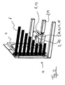
- Fig. 1 shows a cigarette carrier 1 with means 2 for receiving and Nachschieben cigarette packs, so-called chutes, and means 3 for receiving and Nachschieben cigarette packs, so-called feed chutes.
- Each cigarette carrier 1 is preferably accessible from both sides for both customers and employees of a self-service shop.
- the number and arrangement of the devices 2, 3 is arbitrary. In a preferred embodiment, the number of devices 2, 3 is the same and the arrangement of the devices 2, 3 as in Fig. 1 represented, arranged in mirror image.
- the devices 2 for the cigarette boxes are in this case arranged above the means 3 for the cigarette packs.
- Each cigarette carrier has at its front and back 4, 5 a shutter grid 6.
- the shutter 6 is partially in Fig. 2 shown.
- For driving each shutter grid 6 is at least one drive 15 provided. This is expediently provided below the device 3.
- Each drive 15 is arranged fixed to recordings 8.
- the at least one preferably electromotive-acting drive 15 drives the shutter grid 6.
- Each shutter grid 6 is guided in tracks 7, wherein the tracks 12 are equipped with curved areas 11.
- Each drive unit 9 has a drive 15, drive wheels 13 and drive arms 14.
- the drive wheels 13 are arranged in the curved regions 11 of the tracks 7.
- the drive 15 causes a rotation of the drive wheels 13 and the drive arms 14, so that the shutter grid 6 can be moved to the desired height along the tracks 7.
- the drive 15 may be formed for example by a motor. Other drives are also conceivable.
- the reinforcing means 10 can be driven mechanically or electronically.
- the reinforcing means 10 is provided in the vicinity of the drive 15.
- the reinforcing means 10 must be able to absorb and store the energy when the shutter grid 6 is lowered. Furthermore, the reinforcing agent 10 has to release this energy again when the closure grid is opened.
- a spring 16 fulfills this task. Feathers have the property to deform elastically under the action of external forces and release the energy absorbed by spring back again.
- the reinforcing means 10 is in the form of a spring 16.
- this is a cylindrical helical compression spring made of flat steel use.
- the spring 16 has in this case windings 18, which are close to each other depending on the state or have a distance from each other.
- the shutter grid 6 is in the closed position and is then lowered to open, the spring 16 stretches by the rotational movement of the drive wheels 13 and the drive arms 14. In this tensioned state, the windings 18 of the spring 16 are arranged without spacing. Upon renewed closing of the closure grid 6, the energy stored in the spring 16 can be released again by the opposite direction of rotation of the drive wheels 13 and the drive arms 14. The distance between the individual windings 18 increases again.
- the reinforcing means 10, like the drive 15, is connected to the cigarette carrier 1 at a receptacle 12.
- the receptacles 8, 12 can also be formed by a receptacle for both the drive 15 and for the reinforcing means 10.
- a stationary connection with one of the drive arms 14 on one side and the drive 15 on the other side is essential in the use of a mechanical reinforcing means 10.
- This connection can be formed for example by a shaft. Other connections are also conceivable.
- each reinforcing means 10, in particular the spring 16 has a housing 17. This serves as protection of the spring 16, but also for safety during the assembly or maintenance of the cigarette carrier 1. A contamination of the spring 16 is also ensured.
- the housing 17 may be formed of a variety of materials.
- the housing 17 is made of a transparent material.
- the spring 16 consists of a radial inner part 19 with an inner opening 20 for receiving, for example, a shaft.
- a winding 18 is arranged around the outer radius of the inner part 19.
- This winding 18 is formed of a durable material, preferably a spring steel. But also non-ferrous metals or non-metallic materials are conceivable.
- the length of the winding 18 and the thickness of the flat wire 22 and thus the diameter are dependent on the length of the tracks 7 at which the shutter grid 6 is guided and the mass of the shutter grid 6 itself.
- the winding 18 has a stabilization 21. This can be formed for example in the form of an outer, closed ring. Other designs are also conceivable.
- Fig. 2 an advantageous arrangement of the reinforcing means 10 is shown on the drive unit 9.
- the reinforcing means 10, in particular a spring 16, is arranged directly next to the drive 15.
- the drive arms 14 are located to the left of the drive 15 and to the right of the reinforcing means 10.
Landscapes
- Engineering & Computer Science (AREA)
- Structural Engineering (AREA)
- Architecture (AREA)
- Civil Engineering (AREA)
- Pinball Game Machines (AREA)
- Vending Machines For Individual Products (AREA)
- Wrapping Of Specific Fragile Articles (AREA)
- Toys (AREA)
Description
- Die Erfindung bezieht sich auf einen Zigarettenträger für SB-Geschäfte mit den Merkmalen im Oberbegriff des Hauptanspruchs.
- Zigarettenträger dieser Art finden sich in Kassenzonen von SB-Geschäften. Vorzugsweise sind sie dort an oder unmittelbar vor Kassentischen angeordnet. Solche Zigarettenträger weisen meist, um Inventurdifferenzen zu vermeiden, Verschlussgitter auf. Kunden können an diesen Zigarettenträgem Zigarettenschachteln und Zigarettenpackungen entnehmen. Hierfür sind die Verschlussgitter jeweils geöffnet. Ein solcher Zigarettenträger ist beispielsweise aus der deutschen Gebrauchsmusterschrift
DE 202 14 425 U1 bekannt. - Die Aufgabe der vorliegenden Erfindung liegt darin, einen besseren Zigarettenträger aufzuzeigen.
- Die Erfindung löst diese Aufgabe mit den Merkmalen im Hauptanspruch.
- Jede Antriebseinheit weist genügend Platz für die Aufnahme wenigstens eines Verstärkungsmittels auf.
- Durch die Verstärkung der Antriebseinheit mittels eines Verstärkungsmittels ist das Halten des Verschlussgitters an einer gewünschten Position gewährleistet. Das Verschlussgitter ist vorteilhafterweise selbsttätig mittels einer an der der Kasse vorgesehenen Steuerung zu öffnen, zu schließen oder an einer bestimmten Höhe zu halten. Unter Umständen ist ein Halt an einer bestimmten Höhe oder ein "Not Halt" des Verschlussgitters notwendig. Dies kann durch die Kassiererin von der Kasse ausgelöst werden. Das Einhalten einer bestimmten Höhe falls notwendig einer "Not Halt"-Position kann mittels der Verstärkung der Antriebseinheit erreicht werden.
- Die Antriebseinheit ist für das Öffnen, Schließen und Halten des Verschlussgitters vorgesehen. Durch eine Verstärkung der Antriebseinheit kann unter Umständen sogar der Antrieb in seiner Leistung verringert werden. Im Falle einer mechanischen Verstärkung und einer elektronisch betriebenen Antriebseinheit lässt sich zusätzlich der Energiebedarf des Antriebs reduzieren. Das erspart Kosten.
- Nachfolgend ist die Erfindung anhand eines Ausführungsbeispiels näher erläutert. Es zeigt:
- Fig. 1
- einen Zigarettenträger mit Einrichtungen und einer Antriebseinheit für ein Verschlussgitter sowie
- Fig. 2
- einen Ausschnitt des in
Fig. 1 dargestellten Zigarettenträgers mit einer Antriebseinheit und mit einem Verstärkungsmittel. -
Fig. 1 zeigt einen Zigarettenträger 1 mit Einrichtungen 2 zum Aufnehmen und Nachschieben von Zigarettenschachteln, so genannten Schütten, und Einrichtungen 3 zum Aufnehmen und Nachschieben von Zigarettenpackungen, so genannten Vorschubschächten. Jeder Zigarettenträger 1 ist vorzugsweise von beiden Längsseiten sowohl für Kunden als auch für Mitarbeiter eines SB-Geschäftes zugänglich. Die Anzahl und die Anordnung der Einrichtungen 2, 3 ist frei wählbar. In einer bevorzugten Ausführung ist die Anzahl der Einrichtungen 2, 3 gleich und die Anordnung der Einrichtungen 2, 3 wie inFig. 1 dargestellt, spiegelbildlich angeordnet. Die Einrichtungen 2 für die Zigarettenschachteln sind hierbei oberhalb der Einrichtungen 3 für die Zigarettenpackungen angeordnet. - Jeder Zigarettenträger weist an seiner Vorder- und Rückseite 4, 5 ein Verschlussgitter 6 auf. Das Verschlussgitter 6 ist ausschnittsweise in
Fig. 2 dargestellt. Zum Antreiben jedes Verschlussgitters 6 ist wenigstens ein Antrieb 15 vorgesehen. Dieser ist zweckmäßigerweise unterhalb der Einrichtung 3 vorgesehen. Jeder Antrieb 15 ist an Aufnahmen 8 ortfest angeordnet. Der wenigstens eine vorzugsweise elektromotorisch wirkende Antrieb 15 treibt das Verschlussgitter 6 an. Jedes Verschlussgitter 6 ist in Bahnen 7 geführt, wobei die Bahnen 12 mit Krümmungsbereichen 11 ausgestatteten sind. - Jede Antriebseinheit 9 weist einen Antrieb 15, Antriebsräder 13 und Antriebsarme 14 auf. Die Antriebsräder 13 sind in den Krümmungsbereichen 11 der Bahnen 7 angeordnet. Der Antrieb 15 bewirkt eine Rotation der Antriebsräder 13 und der Antriebsarme 14, so dass das Verschlussgitter 6 in die gewünschte Höhe entlang der Bahnen 7 bewegt werden kann. Hierbei kann der Antrieb 15 beispielsweise durch einen Motor gebildet sein. Andere Antriebe sind auch denkbar.
- Um das Verschlussgitter 6 in einer gewünschten Position zu halten, weist die Antriebseinheit 9 ein, in
Fig. 2 näher dargestelltes, Verstärkungsmittel 10 auf. Das Verstärkungsmittel 10 kann mechanisch oder elektronisch angetrieben werden. Vorzugsweise ist das Verstärkungsmittel 10 in der Nähe des Antriebs 15 vorgesehen. - Das Verstärkungsmittel 10 muss in der Lage sein, die Energie beim Herunterlassen des Verschlussgitters 6 aufzunehmen und zu speichern. Weiterhin hat das Verstärkungsmittel 10 diese Energie beim Öffnen des Verschlussgitters wieder abzugeben.
- Eine Feder 16 erfüllt diese Aufgabe. Federn haben die Eigenschaft sich unter der Einwirkung äußerer Kräfte elastisch zu verformen und die dabei aufgenommene Energie durch Rückfederung wieder abzugeben.
- Daher weist das Verstärkungsmittel 10 in einer bevorzugten mechanischen Variante die Form einer Feder 16 auf. Vorzugsweise findet hierbei eine zylindrische Schraubendruckfeder aus Flachstahl Einsatz. Die Feder 16 weist hierbei Wicklungen 18 auf, die je nach Zustand eng aneinander liegen oder einen Abstand zueinander aufweisen.
- Befindet sich das Verschlussgitter 6 in geschlossener Position und wird dann zum Öffnen heruntergelassen, spannt sich die Feder 16 durch die rotierende Bewegung der Antriebsräder 13 und der Antriebsarme 14. In diesem gespannten Zustand sind die Wicklungen 18 der Feder 16 ohne Abstand zueinander angeordnet. Bei erneutem Schließen des Verschlussgitters 6 kann durch die entgegengesetzte Rotationsrichtung der Antriebsräder 13 und der Antriebsarme 14 die in der Feder 16 gespeicherte Energie wieder abgegeben werden. Der Abstand zwischen den einzelnen Wicklungen 18 vergrößert sich wieder.
- Das Verstärkungsmittel 10 ist, wie der Antrieb 15, an einer Aufnahme 12 mit dem Zigarettenträger 1 verbunden. Die Aufnahmen 8, 12 können auch durch eine Aufnahme sowohl für den Antrieb 15 als auch für das Verstärkungsmittel 10 gebildet sein.
- Weiterhin muss die Möglichkeit gegeben sein, dass die Drehbewegung der Antriebsräder 13 und der Antriebsarme 14 auf das Verstärkungsmittel 10 übertragen werden kann. Eine ortsfeste Verbindung mit einem der Antriebsarme 14 auf der einen Seite und dem Antrieb 15 auf der anderen Seite ist bei dem Einsatz eines mechanischen Verstärkungsmittels 10 unabdingbar. Diese Verbindung kann beispielsweise durch eine Welle gebildet sein. Andere Verbindungen sind auch denkbar.
- Vorzugsweise weist jedes Verstärkungsmittel 10, insbesondere die Feder 16, ein Gehäuse 17 auf. Dieses dient als Schutz der Feder 16, aber auch zur Sicherheit während der Bestückung oder der Wartung des Zigarettenträgers 1. Eine Verschmutzung der Feder 16 ist darüber hinaus gewährleistet. Das Gehäuse 17 kann aus den verschiedensten Materialien gebildet werden. Vorzugsweise ist das Gehäuse 17 aus einem durchsichtigen Material gefertigt.
- Die Feder 16 besteht aus einem radialen Innenteil 19 mit einer inneren Öffnung 20 zur Aufnahme auf beispielsweise eine Welle. Um den äußeren Radius des Innenteils 19 ist eine Wicklung 18 angeordnet. Diese Wicklung 18 ist aus einem dauerbeständigen Material, vorzugsweise einem Federstahl, gebildet. Aber auch Nichteisenmetalle oder nichtmetallische Werkstoffe sind denkbar. Die Länge der Wicklung 18 und die Stärke des Flachdrahts 22 und somit der Durchmesser sind abhängig von der Länge der Bahnen 7 an denen das Verschlussgitter 6 geführt wird und von der Masse des Verschlussgitters 6 selbst. Vorzugsweise weist die Wicklung 18 eine Stabilisierung 21 auf. Diese kann beispielsweise in Form eines äußeren, verschlossenen Ringes gebildet sein. Andere Ausführungen sind auch denkbar.
- In
Fig. 2 ist eine vorteilhafte Anordnung des Verstärkungsmittels 10 an der Antriebseinheit 9 aufgezeigt. Das Verstärkungsmittel 10, insbesondere eine Feder 16, ist direkt neben dem Antrieb 15 angeordnet. Die Antriebsarme 14 befinden sich links vom Antrieb 15 und rechts von dem Verstärkungsmittel 10.
Claims (10)
- Zigarettenträger für SB-Geschäfte mit einer Einrichtung (2) zum Aufnehmen und Nachschieben von Zigarettenschachteln, sowie einer Einrichtung (3) zum Aufnehmen und Nachschieben von Zigarettenpackungen, wobei der Zigarettenträger (1) durch wenigstens ein vorzugsweise elektromotorisch angetriebenes Verschlussgitter (6) verschließbar ist, wobei das Verschlussgitter (6) an Bahnen (7) geführt ist und wobei die wenigstens eine Antriebseinheit (9), die an einer Aufnahme (8) ortsfest angeordnet ist, das Verschlussgitter (6) auf eine gewünschte Höhen bringt, dadurch gekennzeichnet, dass die wenigstens eine Antriebseinheit (9) mit wenigstens einem Verstärkungsmittel zum Halten des Verschlussgitters an einer gewünschten Position (10) ausgestattet ist.
- Zigarettenträger nach Anspruch 1 dadurch gekennzeichnet, dass die Antriebseinheit (9) Antriebsräder (13) und Antriebsarme (14) aufweist, wobei die Antriebsräder (13) jeweils an den Enden der Antriebsarme (14) angeordnet sind.
- Zigarettenträger nach den Ansprüchen 1 oder 2 dadurch gekennzeichnet, dass das wenigstens eine Verstärkungsmittel (10) mechanisch oder elektronisch angetrieben ist.
- Zigarettenträger nach einem der Ansprüche 1 bis 3 dadurch gekennzeichnet, dass das wenigstens eine Verstärkungsmittel (10) vorzugsweise durch eine Feder (16) gebildet ist.
- Zigarettenträger nach einem der Ansprüche 1 bis 4 dadurch gekennzeichnet, dass das wenigstens eine Verstärkungsmittel (10) vorzugsweise in der Nähe des Antriebs (15) angeordnet ist.
- Zigarettenträger nach einem der Ansprüche 1 bis 5 dadurch gekennzeichnet, dass das wenigstens eine Verstärkungsmittel (10), insbesondere die Feder (16), ein Gehäuse (17) aufweist.
- Zigarettenträger nach einem der Ansprüche 1 bis 6 dadurch gekennzeichnet, dass die Wicklungen (18) der Feder (16) vorzugsweise aus Flachdraht (22) gebildet sind.
- Verfahren zur Herstellung eines Zigarettenträgers mit einem Verstärkungsmittel dadurch gekennzeichnet, dass die bevorzugte Gestaltung des Verstärkungsmittels (10) in Form einer Feder (16), anhand der Länge der Bahnen (7) und/oder der Masse des Verschlussgitters (6) ausgelegt ist.
- Verfahren zur Herstellung eines Zigarettenträgers mit einem Verstärkungsmittel nach Anspruch 8 dadurch gekennzeichnet, dass für das Verstärkungsmittel 10 ein Material zum Einsatz kommt, das die Anforderungen dauerbeständig erfüllt.
- Verfahren zur Herstellung des Verstärkungsmittels nach Anspruch 9 dadurch gekennzeichnet, dass ein Federstahl Verwendung findet.
Applications Claiming Priority (2)
| Application Number | Priority Date | Filing Date | Title |
|---|---|---|---|
| DE102005034152A DE102005034152A1 (de) | 2005-07-19 | 2005-07-19 | Zigarettenträger |
| PCT/EP2006/006403 WO2007009571A1 (de) | 2005-07-19 | 2006-06-30 | Zigarettenträger |
Publications (2)
| Publication Number | Publication Date |
|---|---|
| EP1916927A1 EP1916927A1 (de) | 2008-05-07 |
| EP1916927B1 true EP1916927B1 (de) | 2009-06-17 |
Family
ID=37027031
Family Applications (1)
| Application Number | Title | Priority Date | Filing Date |
|---|---|---|---|
| EP06754643A Not-in-force EP1916927B1 (de) | 2005-07-19 | 2006-06-30 | Zigarettenträger |
Country Status (4)
| Country | Link |
|---|---|
| EP (1) | EP1916927B1 (de) |
| AT (1) | ATE433691T1 (de) |
| DE (2) | DE102005034152A1 (de) |
| WO (1) | WO2007009571A1 (de) |
Family Cites Families (8)
| Publication number | Priority date | Publication date | Assignee | Title |
|---|---|---|---|---|
| DE7407712U (de) * | 1974-08-01 | Reemtsma H & P | Verkaufsbehälter | |
| DE7723850U1 (de) * | 1977-07-30 | 1980-01-17 | B.A.T. Cigaretten-Fabriken Gmbh, 2000 Hamburg | Warentraeger |
| FR2621069B1 (fr) * | 1987-09-25 | 1989-12-22 | Somaco | Dispositif de securite de porte a rideau |
| DE29602537U1 (de) * | 1996-02-14 | 1996-04-11 | Wanzl Metallwarenfabrik Gmbh, 89340 Leipheim | Gehäuseartiger Warenträger |
| DE29820417U1 (de) * | 1998-08-12 | 1999-12-23 | Heinrich J. Kesseböhmer Draht- und Metallwarenfabrik, 49152 Bad Essen | Overhead-Warenausgabebehälter |
| DE10231021A1 (de) * | 2002-07-09 | 2004-01-22 | Aldi Gmbh & Co. Kg | Vorratsbehälter für verschiedene nach Wahl entnehmbare Artikel |
| DE20214425U1 (de) * | 2002-09-17 | 2002-11-21 | Wanzl Metallwarenfabrik Gmbh, 89340 Leipheim | Zigarettenträger für SB-Geschäfte |
| DE20314425U1 (de) * | 2003-09-17 | 2005-01-27 | Savage, Elke | Handtasche |
-
2005
- 2005-07-19 DE DE102005034152A patent/DE102005034152A1/de not_active Withdrawn
-
2006
- 2006-06-30 EP EP06754643A patent/EP1916927B1/de not_active Not-in-force
- 2006-06-30 DE DE502006004015T patent/DE502006004015D1/de not_active Expired - Fee Related
- 2006-06-30 WO PCT/EP2006/006403 patent/WO2007009571A1/de not_active Ceased
- 2006-06-30 AT AT06754643T patent/ATE433691T1/de not_active IP Right Cessation
Also Published As
| Publication number | Publication date |
|---|---|
| DE102005034152A1 (de) | 2007-01-25 |
| ATE433691T1 (de) | 2009-07-15 |
| EP1916927A1 (de) | 2008-05-07 |
| WO2007009571A1 (de) | 2007-01-25 |
| DE502006004015D1 (de) | 2009-07-30 |
Similar Documents
| Publication | Publication Date | Title |
|---|---|---|
| DE3517290A1 (de) | Einsatzfahrzeug, insbesondere feuerwehrfahrzeug | |
| EP1061013A1 (de) | Lagerregal | |
| EP3085856B1 (de) | Aufbewahrungssystem für fahrzeuge | |
| EP1803878A3 (de) | Dekompressionsverschluss | |
| DE102013013978A1 (de) | Werkzeugterminal mit konzentrischen Blechwänden | |
| DE102014000680A1 (de) | Kraftfahrzeugschloss mit Positionssicherung | |
| EP2907951B1 (de) | Gewerbliches Kühlregal | |
| EP2110220A2 (de) | Vorrichtung zur Herstellung von Formteilen, insbesondere von Schaumformteilen | |
| EP4019733B1 (de) | Durchgangsschleuse | |
| WO2020078492A1 (de) | Selbsteinzugsvorrichtung mit speicherladevorrichtung | |
| WO2007009571A1 (de) | Zigarettenträger | |
| EP2347680B1 (de) | Abdeckung für Kühltruhen sowie Kühltruhe | |
| DE202005011528U1 (de) | Zigarettenträger | |
| EP3318714A1 (de) | Artikel-ausgabesystem | |
| EP2510293B1 (de) | Schiebetürsystem für kühlgeräte | |
| EP1834549A1 (de) | Overhead-Warenausgabebehälter | |
| DE202017005797U1 (de) | Tragende Struktur für einen Multicopter | |
| CH440872A (de) | Schliessvorrichtung, insbesondere für Autoklaven | |
| DE10231021A1 (de) | Vorratsbehälter für verschiedene nach Wahl entnehmbare Artikel | |
| DE2502626A1 (de) | Warenschachteinrichtung fuer einen selbstverkaeufer | |
| DE29915018U1 (de) | Automatische Tür, insbesondere Schiebetür | |
| DE20109059U1 (de) | Fahrzeug, insbesondere Nutzfahrzeug | |
| DE102019208681A1 (de) | Verfahren zum Beladen eines Aufbewahrungssystems eines Kraftfahrzeuges mit Transportgütern | |
| DE202024106987U1 (de) | Kassentisch mit bewegbarem Förderbandgestell | |
| DE202016107335U1 (de) | Betätigungstechnik für Gebäudetüren |
Legal Events
| Date | Code | Title | Description |
|---|---|---|---|
| PUAI | Public reference made under article 153(3) epc to a published international application that has entered the european phase |
Free format text: ORIGINAL CODE: 0009012 |
|
| 17P | Request for examination filed |
Effective date: 20080219 |
|
| AK | Designated contracting states |
Kind code of ref document: A1 Designated state(s): AT BE BG CH CY CZ DE DK EE ES FI FR GB GR HU IE IS IT LI LT LU LV MC NL PL PT RO SE SI SK TR |
|
| GRAP | Despatch of communication of intention to grant a patent |
Free format text: ORIGINAL CODE: EPIDOSNIGR1 |
|
| GRAS | Grant fee paid |
Free format text: ORIGINAL CODE: EPIDOSNIGR3 |
|
| GRAA | (expected) grant |
Free format text: ORIGINAL CODE: 0009210 |
|
| AK | Designated contracting states |
Kind code of ref document: B1 Designated state(s): AT BE BG CH CY CZ DE DK EE ES FI FR GB GR HU IE IS IT LI LT LU LV MC NL PL PT RO SE SI SK TR |
|
| REG | Reference to a national code |
Ref country code: GB Ref legal event code: FG4D Free format text: NOT ENGLISH |
|
| REG | Reference to a national code |
Ref country code: CH Ref legal event code: EP |
|
| REG | Reference to a national code |
Ref country code: IE Ref legal event code: FG4D Free format text: LANGUAGE OF EP DOCUMENT: GERMAN |
|
| REF | Corresponds to: |
Ref document number: 502006004015 Country of ref document: DE Date of ref document: 20090730 Kind code of ref document: P |
|
| PG25 | Lapsed in a contracting state [announced via postgrant information from national office to epo] |
Ref country code: FI Free format text: LAPSE BECAUSE OF FAILURE TO SUBMIT A TRANSLATION OF THE DESCRIPTION OR TO PAY THE FEE WITHIN THE PRESCRIBED TIME-LIMIT Effective date: 20090617 Ref country code: LT Free format text: LAPSE BECAUSE OF FAILURE TO SUBMIT A TRANSLATION OF THE DESCRIPTION OR TO PAY THE FEE WITHIN THE PRESCRIBED TIME-LIMIT Effective date: 20090617 |
|
| PG25 | Lapsed in a contracting state [announced via postgrant information from national office to epo] |
Ref country code: LV Free format text: LAPSE BECAUSE OF FAILURE TO SUBMIT A TRANSLATION OF THE DESCRIPTION OR TO PAY THE FEE WITHIN THE PRESCRIBED TIME-LIMIT Effective date: 20090617 Ref country code: SI Free format text: LAPSE BECAUSE OF FAILURE TO SUBMIT A TRANSLATION OF THE DESCRIPTION OR TO PAY THE FEE WITHIN THE PRESCRIBED TIME-LIMIT Effective date: 20090617 Ref country code: SE Free format text: LAPSE BECAUSE OF FAILURE TO SUBMIT A TRANSLATION OF THE DESCRIPTION OR TO PAY THE FEE WITHIN THE PRESCRIBED TIME-LIMIT Effective date: 20090917 Ref country code: PL Free format text: LAPSE BECAUSE OF FAILURE TO SUBMIT A TRANSLATION OF THE DESCRIPTION OR TO PAY THE FEE WITHIN THE PRESCRIBED TIME-LIMIT Effective date: 20090617 |
|
| PGFP | Annual fee paid to national office [announced via postgrant information from national office to epo] |
Ref country code: DE Payment date: 20090707 Year of fee payment: 4 |
|
| NLV1 | Nl: lapsed or annulled due to failure to fulfill the requirements of art. 29p and 29m of the patents act | ||
| BERE | Be: lapsed |
Owner name: WANZL METALLWARENFABRIK G.M.B.H. Effective date: 20090630 |
|
| REG | Reference to a national code |
Ref country code: IE Ref legal event code: FD4D |
|
| PG25 | Lapsed in a contracting state [announced via postgrant information from national office to epo] |
Ref country code: MC Free format text: LAPSE BECAUSE OF NON-PAYMENT OF DUE FEES Effective date: 20090630 Ref country code: IE Free format text: LAPSE BECAUSE OF FAILURE TO SUBMIT A TRANSLATION OF THE DESCRIPTION OR TO PAY THE FEE WITHIN THE PRESCRIBED TIME-LIMIT Effective date: 20090617 Ref country code: CZ Free format text: LAPSE BECAUSE OF FAILURE TO SUBMIT A TRANSLATION OF THE DESCRIPTION OR TO PAY THE FEE WITHIN THE PRESCRIBED TIME-LIMIT Effective date: 20090617 Ref country code: RO Free format text: LAPSE BECAUSE OF FAILURE TO SUBMIT A TRANSLATION OF THE DESCRIPTION OR TO PAY THE FEE WITHIN THE PRESCRIBED TIME-LIMIT Effective date: 20090617 Ref country code: IS Free format text: LAPSE BECAUSE OF FAILURE TO SUBMIT A TRANSLATION OF THE DESCRIPTION OR TO PAY THE FEE WITHIN THE PRESCRIBED TIME-LIMIT Effective date: 20091017 Ref country code: ES Free format text: LAPSE BECAUSE OF FAILURE TO SUBMIT A TRANSLATION OF THE DESCRIPTION OR TO PAY THE FEE WITHIN THE PRESCRIBED TIME-LIMIT Effective date: 20090928 Ref country code: EE Free format text: LAPSE BECAUSE OF FAILURE TO SUBMIT A TRANSLATION OF THE DESCRIPTION OR TO PAY THE FEE WITHIN THE PRESCRIBED TIME-LIMIT Effective date: 20090617 |
|
| PG25 | Lapsed in a contracting state [announced via postgrant information from national office to epo] |
Ref country code: SK Free format text: LAPSE BECAUSE OF FAILURE TO SUBMIT A TRANSLATION OF THE DESCRIPTION OR TO PAY THE FEE WITHIN THE PRESCRIBED TIME-LIMIT Effective date: 20090617 Ref country code: NL Free format text: LAPSE BECAUSE OF FAILURE TO SUBMIT A TRANSLATION OF THE DESCRIPTION OR TO PAY THE FEE WITHIN THE PRESCRIBED TIME-LIMIT Effective date: 20090617 |
|
| PG25 | Lapsed in a contracting state [announced via postgrant information from national office to epo] |
Ref country code: BG Free format text: LAPSE BECAUSE OF FAILURE TO SUBMIT A TRANSLATION OF THE DESCRIPTION OR TO PAY THE FEE WITHIN THE PRESCRIBED TIME-LIMIT Effective date: 20090917 Ref country code: PT Free format text: LAPSE BECAUSE OF FAILURE TO SUBMIT A TRANSLATION OF THE DESCRIPTION OR TO PAY THE FEE WITHIN THE PRESCRIBED TIME-LIMIT Effective date: 20091017 |
|
| PLBE | No opposition filed within time limit |
Free format text: ORIGINAL CODE: 0009261 |
|
| STAA | Information on the status of an ep patent application or granted ep patent |
Free format text: STATUS: NO OPPOSITION FILED WITHIN TIME LIMIT |
|
| PG25 | Lapsed in a contracting state [announced via postgrant information from national office to epo] |
Ref country code: DK Free format text: LAPSE BECAUSE OF FAILURE TO SUBMIT A TRANSLATION OF THE DESCRIPTION OR TO PAY THE FEE WITHIN THE PRESCRIBED TIME-LIMIT Effective date: 20090617 |
|
| 26N | No opposition filed |
Effective date: 20100318 |
|
| PG25 | Lapsed in a contracting state [announced via postgrant information from national office to epo] |
Ref country code: BE Free format text: LAPSE BECAUSE OF NON-PAYMENT OF DUE FEES Effective date: 20090630 |
|
| REG | Reference to a national code |
Ref country code: FR Ref legal event code: ST Effective date: 20100531 |
|
| PG25 | Lapsed in a contracting state [announced via postgrant information from national office to epo] |
Ref country code: FR Free format text: LAPSE BECAUSE OF NON-PAYMENT OF DUE FEES Effective date: 20090817 |
|
| PG25 | Lapsed in a contracting state [announced via postgrant information from national office to epo] |
Ref country code: AT Free format text: LAPSE BECAUSE OF NON-PAYMENT OF DUE FEES Effective date: 20090630 |
|
| PG25 | Lapsed in a contracting state [announced via postgrant information from national office to epo] |
Ref country code: GR Free format text: LAPSE BECAUSE OF FAILURE TO SUBMIT A TRANSLATION OF THE DESCRIPTION OR TO PAY THE FEE WITHIN THE PRESCRIBED TIME-LIMIT Effective date: 20090918 |
|
| REG | Reference to a national code |
Ref country code: CH Ref legal event code: PL |
|
| GBPC | Gb: european patent ceased through non-payment of renewal fee |
Effective date: 20100630 |
|
| PG25 | Lapsed in a contracting state [announced via postgrant information from national office to epo] |
Ref country code: CH Free format text: LAPSE BECAUSE OF NON-PAYMENT OF DUE FEES Effective date: 20090630 Ref country code: LI Free format text: LAPSE BECAUSE OF NON-PAYMENT OF DUE FEES Effective date: 20090630 Ref country code: IT Free format text: LAPSE BECAUSE OF FAILURE TO SUBMIT A TRANSLATION OF THE DESCRIPTION OR TO PAY THE FEE WITHIN THE PRESCRIBED TIME-LIMIT Effective date: 20090617 |
|
| PG25 | Lapsed in a contracting state [announced via postgrant information from national office to epo] |
Ref country code: DE Free format text: LAPSE BECAUSE OF NON-PAYMENT OF DUE FEES Effective date: 20110101 Ref country code: LI Free format text: LAPSE BECAUSE OF NON-PAYMENT OF DUE FEES Effective date: 20100630 Ref country code: CH Free format text: LAPSE BECAUSE OF NON-PAYMENT OF DUE FEES Effective date: 20100630 Ref country code: LU Free format text: LAPSE BECAUSE OF NON-PAYMENT OF DUE FEES Effective date: 20090630 |
|
| PG25 | Lapsed in a contracting state [announced via postgrant information from national office to epo] |
Ref country code: HU Free format text: LAPSE BECAUSE OF FAILURE TO SUBMIT A TRANSLATION OF THE DESCRIPTION OR TO PAY THE FEE WITHIN THE PRESCRIBED TIME-LIMIT Effective date: 20091218 |
|
| PG25 | Lapsed in a contracting state [announced via postgrant information from national office to epo] |
Ref country code: GB Free format text: LAPSE BECAUSE OF NON-PAYMENT OF DUE FEES Effective date: 20100630 |
|
| PG25 | Lapsed in a contracting state [announced via postgrant information from national office to epo] |
Ref country code: TR Free format text: LAPSE BECAUSE OF FAILURE TO SUBMIT A TRANSLATION OF THE DESCRIPTION OR TO PAY THE FEE WITHIN THE PRESCRIBED TIME-LIMIT Effective date: 20090617 |
|
| PG25 | Lapsed in a contracting state [announced via postgrant information from national office to epo] |
Ref country code: CY Free format text: LAPSE BECAUSE OF FAILURE TO SUBMIT A TRANSLATION OF THE DESCRIPTION OR TO PAY THE FEE WITHIN THE PRESCRIBED TIME-LIMIT Effective date: 20090617 |