EP1916684A1 - Gas-insulated high-voltage circuit breaker - Google Patents
Gas-insulated high-voltage circuit breaker Download PDFInfo
- Publication number
- EP1916684A1 EP1916684A1 EP06405444A EP06405444A EP1916684A1 EP 1916684 A1 EP1916684 A1 EP 1916684A1 EP 06405444 A EP06405444 A EP 06405444A EP 06405444 A EP06405444 A EP 06405444A EP 1916684 A1 EP1916684 A1 EP 1916684A1
- Authority
- EP
- European Patent Office
- Prior art keywords
- throat
- gas
- circuit breaker
- section
- conically
- Prior art date
- Legal status (The legal status is an assumption and is not a legal conclusion. Google has not performed a legal analysis and makes no representation as to the accuracy of the status listed.)
- Withdrawn
Links
Images


Classifications
-
- H—ELECTRICITY
- H01—ELECTRIC ELEMENTS
- H01H—ELECTRIC SWITCHES; RELAYS; SELECTORS; EMERGENCY PROTECTIVE DEVICES
- H01H33/00—High-tension or heavy-current switches with arc-extinguishing or arc-preventing means
- H01H33/70—Switches with separate means for directing, obtaining, or increasing flow of arc-extinguishing fluid
- H01H33/7015—Switches with separate means for directing, obtaining, or increasing flow of arc-extinguishing fluid characterised by flow directing elements associated with contacts
- H01H33/7023—Switches with separate means for directing, obtaining, or increasing flow of arc-extinguishing fluid characterised by flow directing elements associated with contacts characterised by an insulating tubular gas flow enhancing nozzle
- H01H33/703—Switches with separate means for directing, obtaining, or increasing flow of arc-extinguishing fluid characterised by flow directing elements associated with contacts characterised by an insulating tubular gas flow enhancing nozzle having special gas flow directing elements, e.g. grooves, extensions
Definitions
- the invention relates to the field of high-voltage engineering, in particular gas-insulated high-voltage circuit breakers in electrical power distribution systems. It is based on a high-voltage circuit breaker in accordance with the precharacterizing clause of the patent claim 1.
- the main objective of such a circuit breaker is to disconnect a wide range of electric currents in a high-voltage network, whenever it is necessary.
- the underlying disconnection principle is to generate a switching arc between two arcing contacts, to extinguish the switching arc by blowing the arc axially through an insulation nozzle with a quenching gas at current zero and then to isolate the two arcing contacts with the quenching gas.
- the process of extinguishing the arc up to current zero is called the thermal interruption.
- the establishing of the interruption capability of a gap between the two arcing contacts after current zero is called thermal dielectric recovery. In the dielectric recovery phase, a dielectric breakdown may occur if the local electric field in the contact gap exceeds a threshold value.
- a circuit breaker of the afore-mentioned type is described in US 6, 646,850 B1 .
- the described circuit breaker comprises an insulation nozzle including a constriction point from which quenching gas flows in an outlet flow direction through one outlet flow channel having a number of areas which the quenching gas passes through successively.
- a first area facing the constriction point of the nozzle has a specific flow resistance which is less than that of the constriction point.
- a second, a third and a fourth area follow successively in the outlet flow direction, in which the specific flow resistance of the second and the fourth area, respectively, is greater than the specific flow resistance in the immediately preceding area in the outflow direction.
- an insulating nozzle besides a first throat also comprises a second throat which follows a conically increasing section of a gas outlet of the nozzle in the flow direction of the quenching gas. Furthermore during travelling of a second of two arcing contacts through the second throat the ratio of the effective cross section of the second throat to the cross section of the first throat is between 1 and 2.
- strong supersonic expansion in the gas outlet of the nozzle can be controlled such that the creation of dielectrically unfriendly regions are reduced and thus the dielectric recovery capability of the breaker is improved remarkably.
- the reduction of the dielectrically unfriendly regions is due to flow choking in the second nozzle and thus due to localizing regions with supersonic gas flow immediately behind the exit of the first throat.
- the density of the quenching gas thus is comparatively high which leads to an increase of the breakdown voltage of the breaker and thus to an improved dielectric recovery capability.
- Undesired transients in particular capacitive currents, can be interrupted successfully when the second arcing contact carries an annular body which is positioned in such a way that during opening of the circuit breaker the annular body releases the second throat later than the plug head the first throat.
- the contact arrangement of the prior art circuit breaker of fig.1 is extended along an axis 1 and is enclosed in a tubular housing 2 which is filled with an insulating gas, in particular on the basis of sulfur hexafluoride, nitrogen or carbon dioxide or a mixture comprising one or more of these gases.
- an insulating gas in particular on the basis of sulfur hexafluoride, nitrogen or carbon dioxide or a mixture comprising one or more of these gases.
- the insulating gas is pressurized up to some bar, for instance five to eight bar.
- a contact arrangement which comprises two switching pieces 3, 4, which can be moved relative to one another along the axis 1.
- Each switching piece 3 resp. 4 comprise in coaxial arrangement an arcing contact 5 resp. 6 and a main current contact 7 resp. 8 which surrounds the corresponding arcing contact.
- both arcing contacts 5, 6 are surrounded by a tubular insulating nozzle 9 which is fixedly secured to the tubularly designed main current contact 7 and which is preferably manufactured of a polymer on the basis of a polytetrafluorethylene (PTFE).
- PTFE polytetrafluorethylene
- the insulating nozzle comprises a gas inlet 10, a throat 11 which is immediately connected to the gas inlet and a gas outlet 12 which is immediately connected to the throat 11.
- the arcing contact 5 is fixedly arranged in the gas inlet 10 and is rigidly connected to the main current contact 7 by means of an annular disk 13 which separates an annular heating volume 14 from an annular compression room 15 of a piston-cylinder compression device.
- the gas inlet 10 comprises an annularly shaped and predominantly axially guided channel 16 which is positioned between the arcing contact 5 or an auxiliary nozzle (not shown) surrounding the contact 5 and a part of the insulating nozzle surrounding the arcing contact 5.
- the arcing contact 5 which is shaped as a tube receives a head 17 of the arcing contact 6 which is shaped as a plug.
- the switching pieces 3, 4 are disconnected by means of a drive (not shown) which moves the switching piece 3 to the left.
- a current to be interrupted commutates into a current path which includes the arcing contacts 5, 6.
- a switching arc 18 is struck when the arcing contacts 5, 6 are separated:
- the plug head 17 receives a first root of the arc 18, the annularly shaped right end of the arcing contact 5 receives the second root of the arc 18.
- the arc heats up and thus pressurizes the surrounding insulating gas which via channel 16 is guided into the heating volume 14 in which it is stored as quenching gas. Meanwhile the arcing contact 5 travels through the throat 11.
- a flow of pressurized quenching gas passes the nozzle 9 and blows the arc 18 beyond current zero until it extinguishes.
- the quenching gas from the heating volume 14 - if necessary additionally fed with quenching gas pressurized in the compression room 15 - then flows through the gas inlet 10 and the throat 11 in an expansion room 19 which includes the gas outlet 12.
- Dependent on the duration and the amplitude of a current to be interrupted the pressure in the heating volume 14 can reach a value which is a multiple, for instance the tenfold, of the pressure of the insulating gas in the housing 2.
- the velocity of the quenching gas flow in the throat 11 may reach at most Mach number 1.
- the mass flow through the nozzle 9 at a predetermined gas pressure in the gas inlet 10 resp. in the heating volume 14 is optimized (choked flow).
- the nozzle cross sectional area increases conically.
- the quenching gas expands into the expansion room 19.
- the velocity of the gas flow increases to supersonic velocity.
- the density and thus the dielectric strength of the quenching gas are small. The small dielectric strength of the quenching gas thus weakens the dielectric recovery capability of the circuit breaker considerably, that means that after current zero restriking may occur.
- the gas outlet 12 of the insulating nozzle 9 comprises a second throat 20 which follows a conically increasing section 21 in the flow direction of the quenching gas.
- the effective cross section A 2 of the throat 20 then is small enough to enable the creation of a choked flow in the second throat 20 and to generate high density subsonic gas in a dielectrically sensitive region B around the plug head 17.
- the region B is marked in the figures 2 to 5 with a box.
- the effective cross section of the throat 20 is large enough to create weakly supersonic flow only in the conically increasing section 21. Hot gas clogging is then avoided which otherwise can lead to failure of the thermal interruption.
- the throat 20 and the special selection of the ratio R locate a shock which is generated immediately behind the exit of the throat 11 in the conically increasing section 21, such that the dielectrically sensitive region B around the plug head 17 only receives a subsonic gas flow and thus comprises a favourable high density quenching gas.
- the gas density of the quenching gas in the dielectrically sensitive region B could be improved approximately a factor 2.
- the conically increasing section 21 is attached to the throat 11 resp. 20 with an annular edge 22 resp. 23.
- the section 21 then can have a constantly inclined surface which is steeply inclined against the axis 1.
- the dielectric recovery capability of this embodiment can be improved in that the surface of the conically increasing section continuously adapts to the surface of the throat 11 (fig.2, below axis 1). This gives a smoothly expanded contour and a smooth surface to the gas outlet 12, free of discontinuities, and enables an improved control of the expansion of the supersonic flow, which is created at the exit of the throat 11. Otherwise, flow detachment at the wall of the conically increasing section 21 may occur and the dielectrically sensitive region B near the plug head 17 can be submerged in the dielectrically unfavourable low density supersonic region of the gas flow.
- a conically decreasing section 24 which is immediately connected to the second throat 20.
- the connection between the conically increasing section 21 and the conically decreasing section 24 executes a connection section 25 with a concave surface.
- the gas outlet 12 of the nozzle 9 now comprises a smoothly divergent part 26 and a smoothly convergent part 27 which follows the divergent part 26 in the flow direction of the quenching gas.
- the convergent part 27 is used to choke the flow in order to confine the location of the normal shock wave in the divergent part 26.
- the surface of the conically increasing section 21 increases constantly and is steeply inclined against the axis 1.
- a connection section 25 with a cylindrical surface.
- the dielectrically sensitive region B around the plug head 17 comprises quenching gas with a higher gas density.
- the arcing contact 6 carries an annular body 28 which is positioned in such a way that during opening of the circuit breaker the annular body releases the throat 20 later than the plug head 17 the first throat 11.
- the annular body 28 prevents the formation of a flow of quenching gas through the throat 20 for a predetermined time after the plug head 17 has released the throat 11.
- a local pressure increase of about a factor 2 can be achieved in region B.
- the annular body 28 releases the throat 20 the gas flow is no more affected and the quenching gas can blow the arc 18 as afore-described.
- Such an additional local pressure increase in region B is beneficial in the case of switching transient capacitive currents.
Landscapes
- Circuit Breakers (AREA)
Abstract
The circuit breaker comprises in coaxial arrangement two arcing contacts (6) and a tubular insulating nozzle (9). The arcing contacts can be moved relative to one another along an axis (1) in a housing filled with an insulating gas. The nozzle (9) comprises a gas inlet (10), a first throat (11), which is connected to the gas inlet (10), and a gas outlet (12) with a conically increasing section (21) which is connected to the first throat (11). During opening one (6) of the arcing contacts passes the insulating nozzle (9) and receives a root of an arc (18) which is struck between the arcing contacts (5,6) and which heats up the insulating gas to a quenching gas that from the gas inlet (10) through the first throat (11) flows into an expansion room (19) including the gas outlet (12).
In order to improve the dielectric recovery capability of the breaker the gas outlet (12) comprises a second throat (20) which follows the conically increasing section (21) in the flow direction of the quenching gas, and during travelling of the second arcing contact (6) through the second throat (20) the ratio of the effective cross section of the second throat (20) to the cross section of the first throat (11) is greater than 1 and at most 2.
In order to improve the dielectric recovery capability of the breaker the gas outlet (12) comprises a second throat (20) which follows the conically increasing section (21) in the flow direction of the quenching gas, and during travelling of the second arcing contact (6) through the second throat (20) the ratio of the effective cross section of the second throat (20) to the cross section of the first throat (11) is greater than 1 and at most 2.
Description
- The invention relates to the field of high-voltage engineering, in particular gas-insulated high-voltage circuit breakers in electrical power distribution systems. It is based on a high-voltage circuit breaker in accordance with the precharacterizing clause of the
patent claim 1. - The main objective of such a circuit breaker is to disconnect a wide range of electric currents in a high-voltage network, whenever it is necessary. The underlying disconnection principle is to generate a switching arc between two arcing contacts, to extinguish the switching arc by blowing the arc axially through an insulation nozzle with a quenching gas at current zero and then to isolate the two arcing contacts with the quenching gas. The process of extinguishing the arc up to current zero is called the thermal interruption. The establishing of the interruption capability of a gap between the two arcing contacts after current zero is called thermal dielectric recovery. In the dielectric recovery phase, a dielectric breakdown may occur if the local electric field in the contact gap exceeds a threshold value.
- A circuit breaker of the afore-mentioned type is described in
US 6, 646,850 B1 . The described circuit breaker comprises an insulation nozzle including a constriction point from which quenching gas flows in an outlet flow direction through one outlet flow channel having a number of areas which the quenching gas passes through successively. A first area facing the constriction point of the nozzle has a specific flow resistance which is less than that of the constriction point. A second, a third and a fourth area follow successively in the outlet flow direction, in which the specific flow resistance of the second and the fourth area, respectively, is greater than the specific flow resistance in the immediately preceding area in the outflow direction. - Thus in the outflow channel areas having higher specific flow resistance and areas having a lower specific flow resistance alternate. The quenching gas in each case flows through an area having a higher specific flow resistance, in order then to expand in an area having a lower specific flow resistance. This results in a build-up behaviour which produces a number of quenching gas build-up pressure waves which follow one another in time in an area in which the switching arc is burning. This allows the time profile of the quenching gas pressure in the arcing area to be controlled, thus achieving a pressure profile which is optimized for arc quenching and for avoiding restriking of the arc.
- It is an object of the invention as described in the patent claims to specify a gas-insulated high-voltage circuit breaker having a simple design and at the same time an improved dielectric recovery capability.
- In the circuit breaker according to the invention an insulating nozzle besides a first throat also comprises a second throat which follows a conically increasing section of a gas outlet of the nozzle in the flow direction of the quenching gas.
Furthermore during travelling of a second of two arcing contacts through the second throat the ratio of the effective cross section of the second throat to the cross section of the first throat is between 1 and 2. For reason of these features strong supersonic expansion in the gas outlet of the nozzle can be controlled such that the creation of dielectrically unfriendly regions are reduced and thus the dielectric recovery capability of the breaker is improved remarkably. The reduction of the dielectrically unfriendly regions is due to flow choking in the second nozzle and thus due to localizing regions with supersonic gas flow immediately behind the exit of the first throat. In the.dielectrically sensitive regions around a plug head of the second arcing contact the density of the quenching gas thus is comparatively high which leads to an increase of the breakdown voltage of the breaker and thus to an improved dielectric recovery capability. - Undesired transients, in particular capacitive currents, can be interrupted successfully when the second arcing contact carries an annular body which is positioned in such a way that during opening of the circuit breaker the annular body releases the second throat later than the plug head the first throat.
- Further embodiments, advantages and applications of the invention are given in the drawings and in a part of the description which follows.
- There are shown schematically in:
- fig.1
- an axial section through a part of a contact arrangement of a gas-insulated high-voltage circuit breaker according to prior art including two arcing contacts and an insulating nozzle in the closed position of the circuit breaker (shown above an axis) and during opening of the circuit breaker (shown below the axis),
- fig.2
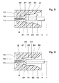
- an axial section through the nozzle and an arcing contact of a first embodiment (shown above the axis) and of a second embodiment (shown below the axis) of the high-voltage circuit breaker according to the invention,
- fig.3
- an axial section through the nozzle and an arcing contact of a third embodiment of the high-voltage circuit breaker according to the invention (shown above the axis) which is compared to the second embodiment according to fig.2 (shown below the axis).
- fig.4
- an axial section through the nozzle and an arcing contact of a fourth embodiment of the circuit breaker according to the invention (shown above the axis) which is compared to the first embodiment according to fig.2 (shown below the axis), and
- fig.5
- an axial section through the nozzle and an arcing contact of a fifth embodiment of the high-voltage circuit breaker according to the invention.
- In the figures same reference symbols are used for identical parts and repetitive reference symbols may be omitted.
- The contact arrangement of the prior art circuit breaker of fig.1 is extended along an
axis 1 and is enclosed in atubular housing 2 which is filled with an insulating gas, in particular on the basis of sulfur hexafluoride, nitrogen or carbon dioxide or a mixture comprising one or more of these gases. Typically the insulating gas is pressurized up to some bar, for instance five to eight bar. Enclosed in thehousing 2 is a contact arrangement which comprises twoswitching pieces axis 1. Eachswitching piece 3 resp. 4 comprise in coaxial arrangement an arcingcontact 5 resp. 6 and a maincurrent contact 7 resp. 8 which surrounds the corresponding arcing contact. In the closed position of the circuit breaker both arcingcontacts insulating nozzle 9 which is fixedly secured to the tubularly designed maincurrent contact 7 and which is preferably manufactured of a polymer on the basis of a polytetrafluorethylene (PTFE). - The insulating nozzle comprises a
gas inlet 10, athroat 11 which is immediately connected to the gas inlet and agas outlet 12 which is immediately connected to thethroat 11. The arcingcontact 5 is fixedly arranged in thegas inlet 10 and is rigidly connected to the maincurrent contact 7 by means of anannular disk 13 which separates anannular heating volume 14 from anannular compression room 15 of a piston-cylinder compression device. Thegas inlet 10 comprises an annularly shaped and predominantly axially guidedchannel 16 which is positioned between the arcingcontact 5 or an auxiliary nozzle (not shown) surrounding thecontact 5 and a part of the insulating nozzle surrounding the arcingcontact 5. - In the closed position of the circuit breaker (shown above axis 1) the arcing
contact 5 which is shaped as a tube receives ahead 17 of the arcingcontact 6 which is shaped as a plug. - In order to open the circuit breaker the
switching pieces switching piece 3 to the left. After the separation of the maincurrent contacts 7, 8 a current to be interrupted commutates into a current path which includes thearcing contacts arc 18 is struck when thearcing contacts plug head 17 receives a first root of thearc 18, the annularly shaped right end of the arcingcontact 5 receives the second root of thearc 18. The arc heats up and thus pressurizes the surrounding insulating gas which viachannel 16 is guided into theheating volume 14 in which it is stored as quenching gas. Meanwhile the arcingcontact 5 travels through thethroat 11. As soon as theplug head 17 releases the throat 11 a flow of pressurized quenching gas passes thenozzle 9 and blows thearc 18 beyond current zero until it extinguishes. The quenching gas from the heating volume 14 - if necessary additionally fed with quenching gas pressurized in the compression room 15 - then flows through thegas inlet 10 and thethroat 11 in anexpansion room 19 which includes thegas outlet 12. Dependent on the duration and the amplitude of a current to be interrupted the pressure in theheating volume 14 can reach a value which is a multiple, for instance the tenfold, of the pressure of the insulating gas in thehousing 2. The velocity of the quenching gas flow in thethroat 11 may reach at most Machnumber 1. The mass flow through thenozzle 9 at a predetermined gas pressure in the gas inlet 10 resp. in theheating volume 14 is optimized (choked flow). - As can be taken from fig. 1 in the
gas outlet 12 the nozzle cross sectional area increases conically. Thus downstream thethroat 11 the quenching gas expands into theexpansion room 19. Hereby the velocity of the gas flow increases to supersonic velocity. In regions of the expansion room in which the flow is supersonic the density and thus the dielectric strength of the quenching gas are small. The small dielectric strength of the quenching gas thus weakens the dielectric recovery capability of the circuit breaker considerably, that means that after current zero restriking may occur. - Such undesired restriking can be reduced with simple means when the
insulating nozzle 9 is designed as shown in the embodiments according to the figures 2 to 5. In all these embodiments thegas outlet 12 of the insulatingnozzle 9 comprises asecond throat 20 which follows a conically increasingsection 21 in the flow direction of the quenching gas. The ratio R of an effective cross section A2 of thesecond throat 20 to the cross section A1 of thefirst throat 11 during travelling of thearcing contact 6 through thethroat 20 exceeds 1 and is at most 2:
- r20 = radius of the
throat 20, - r11 = radius of the
throat 11, and - r6 = radius of the plug-shaped
arcing contact 6. - The effective cross section A2 of the
throat 20 then is small enough to enable the creation of a choked flow in thesecond throat 20 and to generate high density subsonic gas in a dielectrically sensitive region B around theplug head 17. The region B is marked in the figures 2 to 5 with a box. Specifically, the effective cross section of thethroat 20 is large enough to create weakly supersonic flow only in theconically increasing section 21. Hot gas clogging is then avoided which otherwise can lead to failure of the thermal interruption. Thus thethroat 20 and the special selection of the ratio R locate a shock which is generated immediately behind the exit of thethroat 11 in theconically increasing section 21, such that the dielectrically sensitive region B around theplug head 17 only receives a subsonic gas flow and thus comprises a favourable high density quenching gas. - In an embodiment of the high voltage circuit breaker with r6 = 10 mm, r11 = 12 mm, r20 = 18 mm, with a filling pressure of the insulating gas in the
housing 1 of about 7,5 bar and with a pressure of the quenching gas in theheating volume 14 of about 20 bar the gas density of the quenching gas in the dielectrically sensitive region B could be improved approximately afactor 2. - In the embodiment of the circuit breaker according to fig.2 (shown above axis 1) the
conically increasing section 21 is attached to thethroat 11 resp. 20 with anannular edge 22 resp. 23. Thesection 21 then can have a constantly inclined surface which is steeply inclined against theaxis 1. The dielectric recovery capability of this embodiment can be improved in that the surface of the conically increasing section continuously adapts to the surface of the throat 11 (fig.2, below axis 1). This gives a smoothly expanded contour and a smooth surface to thegas outlet 12, free of discontinuities, and enables an improved control of the expansion of the supersonic flow, which is created at the exit of thethroat 11. Otherwise, flow detachment at the wall of theconically increasing section 21 may occur and the dielectrically sensitive region B near theplug head 17 can be submerged in the dielectrically unfavourable low density supersonic region of the gas flow. - In the embodiment according to fig.3 (shown above axis 1) between the conically increasing
section 21 and thesecond throat 20 is arranged a conically decreasingsection 24 which is immediately connected to thesecond throat 20. The connection between the conically increasingsection 21 and theconically decreasing section 24 executes aconnection section 25 with a concave surface. Thegas outlet 12 of thenozzle 9 now comprises a smoothlydivergent part 26 and a smoothlyconvergent part 27 which follows thedivergent part 26 in the flow direction of the quenching gas. Theconvergent part 27 is used to choke the flow in order to confine the location of the normal shock wave in thedivergent part 26. Thedivergent part 26 is used to decelerate the subsonic flow which after a vertical shock at the inlet of thedivergent part 26 is created. The density of the quenching gas in the dielectrically sensitive region B around theplug head 17 thus can be improved additionally compared to the high-voltage circuit breaker of fig.2 (shown below axis 1) having a smoothly openedgas outlet 12. - In the embodiment according to fig.4 (shown above axis 1) the surface of the
conically increasing section 21 increases constantly and is steeply inclined against theaxis 1. Between theconically increasing section 21 and theconically decreasing section 24 is arranged aconnection section 25 with a cylindrical surface. For reason of the steep inclination of thesection 21 and if necessary also of thesection 24 the distance between the arcingcontacts plug head 17 comprises quenching gas with a higher gas density. Thus the dielectric recovery capability of this embodiment is comparatively high. - In the embodiment of the invention according to fig.5 the
arcing contact 6 carries anannular body 28 which is positioned in such a way that during opening of the circuit breaker the annular body releases thethroat 20 later than theplug head 17 thefirst throat 11. During an opening procedure theannular body 28 prevents the formation of a flow of quenching gas through thethroat 20 for a predetermined time after theplug head 17 has released thethroat 11. By means of the annular body 28 a local pressure increase of about afactor 2 can be achieved in region B. When theannular body 28 releases thethroat 20 the gas flow is no more affected and the quenching gas can blow thearc 18 as afore-described. Such an additional local pressure increase in region B is beneficial in the case of switching transient capacitive currents. -
- 1
- axis
- 2
- housing
- 3, 4
- switching pieces
- 5, 6
- arcing contacts
- 7, 8
- main current contacts
- 9
- insulating nozzle
- 10
- gas inlet
- 11
- first throat
- 12
- gas outlet
- 13
- annular disk
- 14
- heating volume
- 15
- compression room
- 16
- channel
- 17
- plug head
- 18
- arc
- 19
- expansion room
- 20
- second throat
- 21
- conically increasing section
- 22,23
- annular edges
- 24
- conically decreasing section
- 25
- connection section
- 26
- divergent part
- 27
- convergent part
- 28
- annular body
- B
- dielectrically sensitive region
- r6
- radius of the plug-shaped
arcing contact 6 - r11
- radius of the
throat 11 - r20
- radius of the
throat 20
Claims (8)
- High-voltage circuit breaker comprising in coaxial arrangement:two arcing contacts (5, 6) which can be moved relative to one another along an axis (1) in a housing (2) filled with an insulating gas, anda tubular insulating nozzle (9) with a gas inlet (10), a first throat (11) which is connected to the gas inlet (10) and a gas outlet (12) with a conically increasing section (21) which is connected to the first throat (11),wherein the first arcing contact (5) is fixedly arranged in the gas inlet (10) and receives a plug head (17) of the second arcing contact (6) in a closed position of the circuit breaker, and
wherein during opening of the circuit breaker the second arcing contact (6) passes the insulating nozzle (9) and receives a root of an arc (18) which is struck between the first (5) and the second arcing contact (6) and which heats up the insulating gas to a quenching gas that from the gas inlet (10) through the first throat (9) flows into an expansion room (19) including the gas outlet (12),
characterized in that the gas outlet (12) comprises a second throat (20) which follows the conically increasing section (21) in the flow direction of the quenching gas, and in that during travelling of the second arcing contact (6) through the second throat (20) the ratio of the effective cross section of the second throat (20) to the cross section of the first throat (11) is greater 1 and at most 2. - The circuit breaker according to claim 1, characterized in that for giving a smoothly expanded contour to the gas outlet (12) the surface of the conically increasing section (21) continuously adapts to the surface of the first throat (11).
- The circuit breaker according to claim 2, characterized in that the second throat (20) is immediately connected to the conically increasing section (21).
- The circuit breaker according to one of claims 1 or 2, characterized in that between the conically increasing section (21) and the second throat (20) is arranged a conically decreasing section (24) which is immediately connected to the second throat (20).
- The circuit breaker according to claim 4, characterized in that between the conically increasing section (21) and the conically decreasing section (24) is arranged a connection section (25) with a concave surface.
- The circuit breaker according to claim 4, characterized in that between the conically increasing section (21) and the conically decreasing section (24) is arranged a connection section (25) with a cylindrical surface.
- The circuit breaker according to claim 6, characterized in that the surface of the conically increasing section (21) increases constantly.
- The circuit breaker according to one of claims 1 to 7, characterized in that the second arcing contact (6) carries an annular body (28) which is positioned in such a way that during opening of the circuit breaker the annular body (28) releases the second throat (20) later than the plug head (17) the first throat (11).
Priority Applications (1)
| Application Number | Priority Date | Filing Date | Title |
|---|---|---|---|
| EP06405444A EP1916684A1 (en) | 2006-10-23 | 2006-10-23 | Gas-insulated high-voltage circuit breaker |
Applications Claiming Priority (1)
| Application Number | Priority Date | Filing Date | Title |
|---|---|---|---|
| EP06405444A EP1916684A1 (en) | 2006-10-23 | 2006-10-23 | Gas-insulated high-voltage circuit breaker |
Publications (1)
| Publication Number | Publication Date |
|---|---|
| EP1916684A1 true EP1916684A1 (en) | 2008-04-30 |
Family
ID=37762539
Family Applications (1)
| Application Number | Title | Priority Date | Filing Date |
|---|---|---|---|
| EP06405444A Withdrawn EP1916684A1 (en) | 2006-10-23 | 2006-10-23 | Gas-insulated high-voltage circuit breaker |
Country Status (1)
| Country | Link |
|---|---|
| EP (1) | EP1916684A1 (en) |
Cited By (2)
| Publication number | Priority date | Publication date | Assignee | Title |
|---|---|---|---|---|
| JP2015011875A (en) * | 2013-06-28 | 2015-01-19 | 株式会社東芝 | Gas circuit breaker |
| WO2017207763A1 (en) | 2016-06-03 | 2017-12-07 | Abb Schweiz Ag | Gas-insulated low- or medium-voltage load break switch |
Citations (3)
| Publication number | Priority date | Publication date | Assignee | Title |
|---|---|---|---|---|
| US3842226A (en) * | 1970-02-06 | 1974-10-15 | K Yoon | Circuit interrupter using a double-throat nozzle |
| EP0135158A2 (en) * | 1983-08-24 | 1985-03-27 | Hitachi, Ltd. | Gas-insulated circuit breaker |
| US4939322A (en) * | 1988-03-25 | 1990-07-03 | Hitachi, Ltd. | Puffer type circuit breaker |
-
2006
- 2006-10-23 EP EP06405444A patent/EP1916684A1/en not_active Withdrawn
Patent Citations (3)
| Publication number | Priority date | Publication date | Assignee | Title |
|---|---|---|---|---|
| US3842226A (en) * | 1970-02-06 | 1974-10-15 | K Yoon | Circuit interrupter using a double-throat nozzle |
| EP0135158A2 (en) * | 1983-08-24 | 1985-03-27 | Hitachi, Ltd. | Gas-insulated circuit breaker |
| US4939322A (en) * | 1988-03-25 | 1990-07-03 | Hitachi, Ltd. | Puffer type circuit breaker |
Cited By (7)
| Publication number | Priority date | Publication date | Assignee | Title |
|---|---|---|---|---|
| JP2015011875A (en) * | 2013-06-28 | 2015-01-19 | 株式会社東芝 | Gas circuit breaker |
| WO2017207763A1 (en) | 2016-06-03 | 2017-12-07 | Abb Schweiz Ag | Gas-insulated low- or medium-voltage load break switch |
| CN109564832A (en) * | 2016-06-03 | 2019-04-02 | Abb瑞士股份有限公司 | Gas-insulating type low pressure or in break load switch |
| CN109564832B (en) * | 2016-06-03 | 2020-09-01 | Abb瑞士股份有限公司 | Gas-insulated low or medium voltage load break switch |
| RU2738087C2 (en) * | 2016-06-03 | 2020-12-08 | Абб Швайц Аг | Gas isolated low or medium voltage load breaker |
| EP3764382A1 (en) | 2016-06-03 | 2021-01-13 | ABB Schweiz AG | Gas-insulated low- or medium-voltage load break switch |
| US10964498B2 (en) | 2016-06-03 | 2021-03-30 | Abb Schweiz Ag | Gas-insulated low- or medium-voltage load break switch |
Similar Documents
| Publication | Publication Date | Title |
|---|---|---|
| EP3465717B1 (en) | Gas-insulated low- or medium-voltage load break switch | |
| WO2013153112A1 (en) | Circuit breaker | |
| CN103000444A (en) | A self-energy SF6 circuit breaker double nozzle type arc extinguishing chamber and its arc extinguishing method | |
| EP1916684A1 (en) | Gas-insulated high-voltage circuit breaker | |
| US6483064B2 (en) | Insulating blast nozzle for a circuit breaker | |
| EP1973133A2 (en) | Circuit breaker using arc contact | |
| KR890002474B1 (en) | Gas-insulated circuit breaker | |
| US4958052A (en) | ARC severing and displacement method and apparatus for fault current interruption | |
| JPS61188825A (en) | Patshua type gas circuit breaker | |
| US10699862B2 (en) | Gas-insulated high-voltage switching device with improved main nozzle | |
| US11127551B2 (en) | Circuit breaker and method of performing a current breaking operation | |
| US20080135523A1 (en) | Self-blast circuit breaker with control body | |
| US4339641A (en) | Nozzle for a puffer-type circuit breaker | |
| JPH07105184B2 (en) | Compressed gas circuit breaker | |
| US4224490A (en) | Fluid blast circuit breaker | |
| US3821507A (en) | Circuit interrupters utilizing supersonic flow | |
| EP2827353A1 (en) | Electrical switching device | |
| EP3433869B1 (en) | Electrical circuit breaker device | |
| US2829221A (en) | Circuit breaker employing opposed fluid blasts | |
| JP7612893B2 (en) | Gas Circuit Breaker | |
| EP4383306B1 (en) | Interrupter unit for gas-insulated high or medium voltage device | |
| EP2837011B1 (en) | Circuit breaker | |
| EP3611745A1 (en) | Gas-insulated low- or medium-voltage load break switch | |
| JPH0439627Y2 (en) | ||
| JP2009054481A (en) | Gas circuit breaker |
Legal Events
| Date | Code | Title | Description |
|---|---|---|---|
| PUAI | Public reference made under article 153(3) epc to a published international application that has entered the european phase |
Free format text: ORIGINAL CODE: 0009012 |
|
| AK | Designated contracting states |
Kind code of ref document: A1 Designated state(s): AT BE BG CH CY CZ DE DK EE ES FI FR GB GR HU IE IS IT LI LT LU LV MC NL PL PT RO SE SI SK TR |
|
| AX | Request for extension of the european patent |
Extension state: AL BA HR MK RS |
|
| AKX | Designation fees paid | ||
| REG | Reference to a national code |
Ref country code: DE Ref legal event code: 8566 |
|
| STAA | Information on the status of an ep patent application or granted ep patent |
Free format text: STATUS: THE APPLICATION IS DEEMED TO BE WITHDRAWN |
|
| 18D | Application deemed to be withdrawn |
Effective date: 20081031 |