EP1916515A1 - Machine for inspecting glass containers - Google Patents
Machine for inspecting glass containers Download PDFInfo
- Publication number
- EP1916515A1 EP1916515A1 EP07118629A EP07118629A EP1916515A1 EP 1916515 A1 EP1916515 A1 EP 1916515A1 EP 07118629 A EP07118629 A EP 07118629A EP 07118629 A EP07118629 A EP 07118629A EP 1916515 A1 EP1916515 A1 EP 1916515A1
- Authority
- EP
- European Patent Office
- Prior art keywords
- container
- machine
- camera
- inspecting
- glass container
- Prior art date
- Legal status (The legal status is an assumption and is not a legal conclusion. Google has not performed a legal analysis and makes no representation as to the accuracy of the status listed.)
- Granted
Links
Images


Classifications
-
- B—PERFORMING OPERATIONS; TRANSPORTING
- B07—SEPARATING SOLIDS FROM SOLIDS; SORTING
- B07C—POSTAL SORTING; SORTING INDIVIDUAL ARTICLES, OR BULK MATERIAL FIT TO BE SORTED PIECE-MEAL, e.g. BY PICKING
- B07C5/00—Sorting according to a characteristic or feature of the articles or material being sorted, e.g. by control effected by devices which detect or measure such characteristic or feature; Sorting by manually actuated devices, e.g. switches
- B07C5/34—Sorting according to other particular properties
- B07C5/3404—Sorting according to other particular properties according to properties of containers or receptacles, e.g. rigidity, leaks, fill-level
- B07C5/3408—Sorting according to other particular properties according to properties of containers or receptacles, e.g. rigidity, leaks, fill-level for bottles, jars or other glassware
-
- G—PHYSICS
- G01—MEASURING; TESTING
- G01N—INVESTIGATING OR ANALYSING MATERIALS BY DETERMINING THEIR CHEMICAL OR PHYSICAL PROPERTIES
- G01N21/00—Investigating or analysing materials by the use of optical means, i.e. using sub-millimetre waves, infrared, visible or ultraviolet light
- G01N21/84—Systems specially adapted for particular applications
- G01N21/88—Investigating the presence of flaws or contamination
- G01N21/90—Investigating the presence of flaws or contamination in a container or its contents
- G01N21/9054—Inspection of sealing surface and container finish
Definitions
- the present invention relates to machines, which inspect glass containers for defects, and more particularly, to a system which inspects for cracks in translucent glass containers.
- Checks can range from sub millimeters to several hundred millimeters and can be oriented at any direction from vertical to horizontal. Glass is not a crystalline structure by nature, but most cracks propagate roughly along a plane of some orientation in space mostly determined by the shape of the glass at that location. For example, a crack that began as a vertical crack at the upper surface of the mouth primarily propagates in a vertical plane. Checks can appear in any orientation and on any portion of a container and can exist wholly within the glass or may penetrate to one or both surfaces. Checks are considered phase objects and do not absorb light like a solid objects does.
- Checks are primarily reflective in nature if their opposed surface separation is at least half a wavelength of light. However, very few checks with a smaller separation will reflect light and accordingly they will not likely be detectable by direct reflection methods, but they might have scattering points when they penetrate to the one or both surfaces of the container and will scatter light back to the sensors.
- finish checks refers to the portion of the bottle that defines the mouth, threads or beads, and the ring.
- the upper surface of the mouth is referred as the sealing surface.
- a conventional check detector consists of a series of continuously operating light spot light sources and associated photodetectors that are positioned so that known checks on a bottle rotating at an inspection station will reflect light from one of the sources to one of the photo-detectors. Signal processing of the photodetector outputs recovers the sharp peaks while rejecting lower frequency signal variations caused by ambient light, reflection from the bottle sidewall, etc.
- the containers 10 are transported along a conveyor 12 to an inspection station illustrated in Figure 1.
- the conveyor may be a linear belt or a turret type feed system.
- a container 10 is engaged by upper and lower rear pairs of idler rollers 14 and a front drive wheel 16 so that rotation of the drive wheel in the clockwise direction will rotate the container in the counterclockwise direction.
- There is conveyor dwell of sufficient duration at the inspection machine so that the container can be rotated more than 360 degrees while the inspection takes place.
- a container present sensor 18 will sense the presence of a container at the inspection station (the sensor can be upstream and the actual presence of the container at the inspection station could be defined by an encoder count following the sensing of the container by the upstream part present sensor).
- Light sources (Light Source #1/20 (see Figures 1 and 2) and Light Source #2/21) illuminate the finish portion of the container and a Camera/22 images the finish portion.
- FIG. 2 illustrates the operation of the Camera and Light Sources.
- a Computer 24 delivers On/Off signals to Light Source #1/20 and Light Source #2/21 and delivers Camera Trigger signals to the Camera/22.
- the Camera has a matrix array of elements (pixels) to receive an image of the finish portion of the container during the Camera's exposure period.
- the Camera could be a CCD, MOS or like camera which will store an image until the next Trigger Signal.
- a Trigger Signal is received, the existing image will be captured and transferred, as an "Acquisition", to the Computer so that it can be recorded and processed by the Computer.
- the Computer will issue a Reject Signal if a defect is identified.
- the Light Axis for each light source is horizontal and intersects the axis "A" of the container.
- Each Light Axis also lies in a vertical or "Z" plane (not shown) which intersects the axis "A" of the container, and is a positive plane in that it is in front of the container.
- the two light axes are orthogonal to each other and 45° to a vertical or "Z" plane including the Camera Detector Axis.
- the Detector Axis for the Camera/22 which is located in a negative "Z" plane in that it is behind the container, is approximately 45° from horizontal. With this relationship, the camera is looking at a dark field and seeing only light coming from the checks.
- the light sources and camera are supported by structure 28 that can be vertically displaced and horizontally displaced to reposition the system for different height/diameter containers.
- the machine will Transfer A Bottle To The Inspection Station/30. Following a time sufficient for the rotation of the bottle, by the drive wheel, to become stable, the Computer will Trigger The Camera/32. This starts the acquisition of the image.
- instructions may be time based rather than defining actual angles so that when something is to occur in an approximate ⁇ ° (60° angle in the preferred embodiment), an approximate time (number of pulses) may be selected which approximately corresponds to that angle, and where events are desired approximately every 7.5°, for example, the pulses could be divided by 8.
- the critical addition will be made in a manner that will maximize the data that indicates that a defect is present.
- the Critical Addition can represent for each pixel location, the highest intensity of the corresponding pixel in all six Acquisitions which will make up the Critical Addition. Then, when the Computer answers the inquiry Next Bottle?/44 in the affirmative, the next bottle can be processed.
- An image processing technique may be used to enhance the signal created by checks from signals created by mold features of the container.
- a reference or "mask image” can be created using a set of sample containers without defects running through the inspection setup (containers without defects are referred as "good ware” and containers with defects that need to be removed during the inspection as "bad ware”).
- good ware containers without defects
- bad ware containers with defects that need to be removed during the inspection
- a large number of images can be acquired and processed to create the mask image. These images contain almost all the possible variations of light reflection by mold marks, threads, seams, and curved surface of good ware.
- Mask image is created by combining all the good ware images. A mask image is created and is compared with the reference mask created with good ware. The difference between the image and the mask shows the signals created by check defects.
- Figure 6 illustrates the operation of the light sources.
- ⁇ is, in the preferred embodiment, defined so that the surface will be illuminated a small portion (25%) of the angle ⁇ °, e.g. by strobing the light sources for the entire time the camera is triggered. Checks that will cause a container to be rejected have been found to be imaged when the light sources are "on" only a small fraction of ⁇ °. This fraction can be empirically varied to achieve a desired result.
- imaging process has been disclosed with reference to checks in the finish area of the container, it can be used to inspect other selected areas of containers, for example to identify body or heel checks and other defects.
- Figure 7 is a timing diagram for an Acquisition comprised of light sources turned on ⁇ degrees for every ⁇ °(7.5° in the preferred embodiment) through ⁇ ° (60° in the preferred embodiment). The lower the ratio of ⁇ / ⁇ °, the less noise will be available to interfere with the desired signal.
- the light sources 20 and 21 shown schematically in Figure 1 are mirror images and are represented as segments of an arc. These segments may be arcuate in both vertical and horizontal directions relative to the light axes. However, it is not essential for the segments or light sources to be physically arcuate or curved, and other means may be provided to achieve the required direction or pattern of illumination.
- each light source 70 may be a flat panel or segment having vertical or generally upright columns and horizontal or generally horizontal rows of LEDs (not visible in Figure 9) with the individual LEDs oriented, i.e. inclined, so that their optical axes are directed in the required directions. Therefore, the flat panel is effectively optically equivalent to an arcuate or approximately part-conical segment.
- the light source 70 mounted on a flat panel 71, is perpendicular to the Light Axis and faces the finish of the container 10 which is shown in dotted lines.
- the segment has inner and outer (or three or four,..) columns of LEDs 72 with the central LEDs 74, which define the Light Axis, standing parallel to the Light Axis and with the remaining LEDs or rows of LEDs being progressively tilted toward the light axis as they proceed away from the Light Axis.
- the locations of the LEDs in each column may follow an arcuate path on or in the flat panel 71 as shown in Figure 8.
- the progressive tilting or bending of the individual LEDs is indicated by the darkened semicircles, and, in the upper and lower regions of the panel 71, by the displacement of the front faces of the LEDs (shown as full-line circles) relative to their mountings (shown as broken-line circles).
- the preferred location of the Light Axis is at the sealing surface 74 but it can be located from the sealing surface to the bottom of the finish.
- the ideal geometry that the preferred embodiment attempts to approach is that of conical illumination (the cone being horizontal with its apex at the finish), where the top and bottom of the cone are dark so that the camera will not see any direct reflections of light. Viewing the finish as a torus, this conical geometry allows the maximum light to be projected onto the finish with direct reflection. Only an anomaly in the finish (a check) will generate direct reflections to the camera.
- This apparatus has following advantages: because the area sensor, i.e. the camera, images an area of the bottle, it is possible to detect almost all the checks in that region. This makes the inspection independent of the specific orientation and location of the check, and thus enables "new" checks to be detected without changing the setup.
- the positioning of the area array sensors and light sources will not depend essentially on the geometry of the bottle. It will be easier to setup for most of the containers with little or no adjustments.
Landscapes
- Physics & Mathematics (AREA)
- Health & Medical Sciences (AREA)
- Life Sciences & Earth Sciences (AREA)
- Chemical & Material Sciences (AREA)
- Analytical Chemistry (AREA)
- Biochemistry (AREA)
- General Health & Medical Sciences (AREA)
- General Physics & Mathematics (AREA)
- Immunology (AREA)
- Pathology (AREA)
- Investigating Materials By The Use Of Optical Means Adapted For Particular Applications (AREA)
- Length Measuring Devices By Optical Means (AREA)
Abstract
Description
- The present invention relates to machines, which inspect glass containers for defects, and more particularly, to a system which inspects for cracks in translucent glass containers.
- In the glass container industry, small cracks or fracture in the glass are referred to as "check defects" or "checks". Checks can range from sub millimeters to several hundred millimeters and can be oriented at any direction from vertical to horizontal. Glass is not a crystalline structure by nature, but most cracks propagate roughly along a plane of some orientation in space mostly determined by the shape of the glass at that location. For example, a crack that began as a vertical crack at the upper surface of the mouth primarily propagates in a vertical plane. Checks can appear in any orientation and on any portion of a container and can exist wholly within the glass or may penetrate to one or both surfaces. Checks are considered phase objects and do not absorb light like a solid objects does. Checks are primarily reflective in nature if their opposed surface separation is at least half a wavelength of light. However, very few checks with a smaller separation will reflect light and accordingly they will not likely be detectable by direct reflection methods, but they might have scattering points when they penetrate to the one or both surfaces of the container and will scatter light back to the sensors.
- Most of these crack defects will drastically weaken the bottle, often causing it to rupture or to leak. Therefore, bottle manufactures like to remove these containers before they reach filing plants. Checks appearing near the mouth of the containers are called finish checks. In the glass bottle industry, the term "container finish" refers to the portion of the bottle that defines the mouth, threads or beads, and the ring. The upper surface of the mouth is referred as the sealing surface.
- Almost all commercially available check detectors work on the principle of reflected light. A conventional check detector consists of a series of continuously operating light spot light sources and associated photodetectors that are positioned so that known checks on a bottle rotating at an inspection station will reflect light from one of the sources to one of the photo-detectors. Signal processing of the photodetector outputs recovers the sharp peaks while rejecting lower frequency signal variations caused by ambient light, reflection from the bottle sidewall, etc.
- While commercially available check detectors are successfully deployed on most glass bottle production lines, there are several drawbacks to the approach. A few of those are: many point sensors are required for many possible reflection angles; some sensor angles are difficult to position; additional sensors and lights need to be added as more production defects appear; time consuming setup is required for each type of container; and the difficulty of reproducing the same setup from one inspection line to another.
-
- It is an object of the present invention to provide an apparatus for inspecting glass containers, which can detect vertical, horizontal, and any other angle cracks on a bottle which is user friendly and easily adjusted. Another object of this invention is to provide a detector that can detect known types of checks and also any new checks without specific setup requirements.
- According to the present invention, there is provided a machine for inspecting a glass container as defined in
claim 1. - The present invention will now be described with reference to the accompanying drawings which illustrate a presently preferred embodiment incorporating the principles of the invention, and in which:-
- Figure 1 is an oblique elevational schematic view of an inspection station of a machine for inspecting glass containers for checks and other defects, made in accordance with the teachings of the present invention.
- Figure 2 is a block diagram showing the operation of the pair of light sources and camera shown in Figure 1;
- Figure 3 is a schematic top view of the container at the inspection station showing the light axes of a pair of light sources and the camera;
- Figure 4 is a schematic elevational view showing the light axes of the light sources and camera shown in Figure 3;
- Figure 5 is a logic diagram illustrating the operation of the camera system of the inspection machine;
- Figure 6 is a logic diagram illustrating the operation of the lighting system of the inspection machine;
- Figure 7 is a timing diagram illustrating the operation of the light sources;
- Figure 8 is a side elevational view of one of the light sources; and
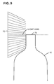
- Figure 9 is an elevational view showing how the LED's of one of the light sources are aimed toward the finish.
- In a machine for inspecting glass containers (bottles), the
containers 10 are transported along a conveyor 12 to an inspection station illustrated in Figure 1. The conveyor may be a linear belt or a turret type feed system. Acontainer 10 is engaged by upper and lower rear pairs ofidler rollers 14 and afront drive wheel 16 so that rotation of the drive wheel in the clockwise direction will rotate the container in the counterclockwise direction. There is conveyor dwell of sufficient duration at the inspection machine so that the container can be rotated more than 360 degrees while the inspection takes place. A containerpresent sensor 18 will sense the presence of a container at the inspection station (the sensor can be upstream and the actual presence of the container at the inspection station could be defined by an encoder count following the sensing of the container by the upstream part present sensor). Light sources (Light Source # 1/20 (see Figures 1 and 2) andLight Source # 2/21) illuminate the finish portion of the container and a Camera/22 images the finish portion. - Figure 2 illustrates the operation of the Camera and Light Sources. A
Computer 24 delivers On/Off signals toLight Source # 1/20 andLight Source # 2/21 and delivers Camera Trigger signals to the Camera/22. The Camera has a matrix array of elements (pixels) to receive an image of the finish portion of the container during the Camera's exposure period. The Camera could be a CCD, MOS or like camera which will store an image until the next Trigger Signal. When a Trigger Signal is received, the existing image will be captured and transferred, as an "Acquisition", to the Computer so that it can be recorded and processed by the Computer. The Computer will issue a Reject Signal if a defect is identified. - As can be seen from Figures 3 and 4, the Light Axis for each light source is horizontal and intersects the axis "A" of the container. Each Light Axis also lies in a vertical or "Z" plane (not shown) which intersects the axis "A" of the container, and is a positive plane in that it is in front of the container. The two light axes are orthogonal to each other and 45° to a vertical or "Z" plane including the Camera Detector Axis. The Detector Axis for the Camera/22, which is located in a negative "Z" plane in that it is behind the container, is approximately 45° from horizontal. With this relationship, the camera is looking at a dark field and seeing only light coming from the checks. The light sources and camera are supported by
structure 28 that can be vertically displaced and horizontally displaced to reposition the system for different height/diameter containers. - With reference to Figure 5, to start an inspection, the machine will Transfer A Bottle To The Inspection Station/30. Following a time sufficient for the rotation of the bottle, by the drive wheel, to become stable, the Computer will Trigger The Camera/32. This starts the acquisition of the image. The following explanation is provided in terms of angles for purposes of clarity, but it should be understood that, in a digitally controlled camera, instructions may be time based rather than defining actual angles so that when something is to occur in an approximate θ° (60° angle in the preferred embodiment), an approximate time (number of pulses) may be selected which approximately corresponds to that angle, and where events are desired approximately every 7.5°, for example, the pulses could be divided by 8. When the query "Has Bottle Rotated θ°?" /34 (θ° or a selected number of pulses corresponding approximately to that angle of rotation can be set) is answered in the affirmative, the Computer will Transfer And Record The Acquisition/36. Once the Camera is triggered, the Camera will capture data until the Camera is again triggered (following the rotation through θ°). When the Computer answers the query "Y Acquisitions?" in the negative, the Computer will again Trigger The Camera/32. When the computer answers the query "Y Acquisitions?" /38 in the affirmative ("Y' may be set and is six in the preferred embodiment), the Computer will Create An Image From Y Acquisitions To be Analyzed/40. The image created (a Critical Addition), where as in the preferred embodiment "Y" is six, will represent the entire (approximately) 360° surface of the finish and will be the Critical Addition of six acquisitions each imaging eight illuminations.
- The critical addition will be made in a manner that will maximize the data that indicates that a defect is present. The Critical Addition can represent for each pixel location, the highest intensity of the corresponding pixel in all six Acquisitions which will make up the Critical Addition. Then, when the Computer answers the inquiry Next Bottle?/44 in the affirmative, the next bottle can be processed.
- An image processing technique may be used to enhance the signal created by checks from signals created by mold features of the container. First, a reference or "mask image", can be created using a set of sample containers without defects running through the inspection setup (containers without defects are referred as "good ware" and containers with defects that need to be removed during the inspection as "bad ware"). To incorporate all the signals created by good ware from different molds that may contain slightly different structural variations, and small variations of signals due to vibrations and rotation, a large number of images can be acquired and processed to create the mask image. These images contain almost all the possible variations of light reflection by mold marks, threads, seams, and curved surface of good ware. Mask image is created by combining all the good ware images. A mask image is created and is compared with the reference mask created with good ware. The difference between the image and the mask shows the signals created by check defects.
- Figure 6 illustrates the operation of the light sources. When the Computer answers the query "Is Image Acquisition To Begin?" /52 in the affirmative, the Computer will Turn Lights "On" For Angle "α"/54 ("α" may be set and could be a defined number of pulses). When the Computer answers the query "Has Container Rotated "ϕ°"/56 in the affirmative (ϕ can be set) , and answers the query "Has Container Rotated θ°?" /58 in the negative, the light sources will again be turned "on". When this inquiry is answered in the affirmative (θ/ϕ pulses per acquisition), and the query Have "Y" Images Been Acquired?/60", in the negative the entire surface has not been imaged and the entire process can be repeated until "Y" images have been acquired (Y pulses per acquisition). Then, when the computer answers the inquiry "Has Next Container Been Sensed?" /62 in the affirmative, the entire process can be repeated for the next bottle. If the lights are to be on for the entire time that the camera is triggered (α can be set to equal θ°).
- To reduce noise, α is, in the preferred embodiment, defined so that the surface will be illuminated a small portion (25%) of the angle ϕ°, e.g. by strobing the light sources for the entire time the camera is triggered. Checks that will cause a container to be rejected have been found to be imaged when the light sources are "on" only a small fraction of ϕ°. This fraction can be empirically varied to achieve a desired result.
- While the imaging process has been disclosed with reference to checks in the finish area of the container, it can be used to inspect other selected areas of containers, for example to identify body or heel checks and other defects.
- Figure 7 is a timing diagram for an Acquisition comprised of light sources turned on α degrees for every ϕ°(7.5° in the preferred embodiment) through θ° (60° in the preferred embodiment). The lower the ratio of α/ϕ°, the less noise will be available to interfere with the desired signal.
- The
light sources - For example, as shown in Figures 8 and 9, in one realization, each
light source 70 may be a flat panel or segment having vertical or generally upright columns and horizontal or generally horizontal rows of LEDs (not visible in Figure 9) with the individual LEDs oriented, i.e. inclined, so that their optical axes are directed in the required directions. Therefore, the flat panel is effectively optically equivalent to an arcuate or approximately part-conical segment. - As shown in Figure 8, the
light source 70, mounted on aflat panel 71, is perpendicular to the Light Axis and faces the finish of thecontainer 10 which is shown in dotted lines. The segment has inner and outer (or three or four,..) columns ofLEDs 72 with thecentral LEDs 74, which define the Light Axis, standing parallel to the Light Axis and with the remaining LEDs or rows of LEDs being progressively tilted toward the light axis as they proceed away from the Light Axis. The locations of the LEDs in each column may follow an arcuate path on or in theflat panel 71 as shown in Figure 8. The progressive tilting or bending of the individual LEDs is indicated by the darkened semicircles, and, in the upper and lower regions of thepanel 71, by the displacement of the front faces of the LEDs (shown as full-line circles) relative to their mountings (shown as broken-line circles). The preferred location of the Light Axis is at the sealingsurface 74 but it can be located from the sealing surface to the bottom of the finish. The ideal geometry that the preferred embodiment attempts to approach is that of conical illumination (the cone being horizontal with its apex at the finish), where the top and bottom of the cone are dark so that the camera will not see any direct reflections of light. Viewing the finish as a torus, this conical geometry allows the maximum light to be projected onto the finish with direct reflection. Only an anomaly in the finish (a check) will generate direct reflections to the camera. - This apparatus has following advantages: because the area sensor, i.e. the camera, images an area of the bottle, it is possible to detect almost all the checks in that region. This makes the inspection independent of the specific orientation and location of the check, and thus enables "new" checks to be detected without changing the setup. The positioning of the area array sensors and light sources will not depend essentially on the geometry of the bottle. It will be easier to setup for most of the containers with little or no adjustments.
Claims (7)
- A machine for inspecting a glass container at an inspection station for defects comprising
means for rotating a glass container at the inspection station,
a light source for illuminating a selected portion of the glass container during rotation of the container,
said light source having a selected "on" time followed by a selected "off" time,
means for turning said light source "on" and "off" consecutively,
said container being rotatable through a defined angle of rotation while said light source is successively "on" and "off" a plurality of times,
a camera including a triggerable imaging portion for imaging the selected illuminated portion of the glass container,
said camera having an exposure time at least equal to the time required for the glass container to rotate through said defined angle of rotation,
means for triggering the imaging portion of said camera when the container is at the beginning and end of at least one of said defined angles of rotation so that the camera will image said selected portion of the container as said glass container rotates through a defined angle of rotation, and
means for capturing and transferring the image when the triggering means is triggered at the end of at least one of said defined angles of rotation. - A machine for inspecting a glass container according to claim 1, wherein the triggering means is triggered a plurality of times.
- A machine for inspecting a glass container according to claim 1 or 2, further comprising means for defining a critical addition of the plurality of recorded images, within a defined angle, for inspection for defects.
- A machine for inspecting glass containers at an inspection station according to claim 1, 2 or 3, wherein the selected portion is the finish portion of the glass container.
- A machine for inspecting glass containers at an inspection station according to any preceding claim, wherein the defect is a check.
- A machine for inspecting glass containers at an inspection station according to any preceding claim, wherein the angle defined by said defined angle of rotation is a portion of 360 degrees.
- A machine for inspecting glass containers at an inspection station according to any preceding claim, wherein said light source comprises a pair of orthogonal related LED panels.
Applications Claiming Priority (3)
| Application Number | Priority Date | Filing Date | Title |
|---|---|---|---|
| US11/585,767 US7626158B2 (en) | 2006-10-23 | 2006-10-23 | Machine for inspecting glass containers |
| US11/585,398 US7541572B2 (en) | 2006-10-23 | 2006-10-23 | Machine for inspecting rotating glass containers with light source triggered multiple times during camera exposure time |
| US11/585,388 US7816639B2 (en) | 2006-10-23 | 2006-10-23 | Machine for inspecting glass containers at an inspection station using an addition of a plurality of illuminations of reflected light |
Publications (2)
| Publication Number | Publication Date |
|---|---|
| EP1916515A1 true EP1916515A1 (en) | 2008-04-30 |
| EP1916515B1 EP1916515B1 (en) | 2014-09-17 |
Family
ID=38956360
Family Applications (1)
| Application Number | Title | Priority Date | Filing Date |
|---|---|---|---|
| EP07118629.0A Ceased EP1916515B1 (en) | 2006-10-23 | 2007-10-16 | Machine for inspecting glass containers |
Country Status (2)
| Country | Link |
|---|---|
| EP (1) | EP1916515B1 (en) |
| JP (1) | JP5425387B2 (en) |
Cited By (3)
| Publication number | Priority date | Publication date | Assignee | Title |
|---|---|---|---|---|
| EP2623962A1 (en) * | 2010-10-01 | 2013-08-07 | Kirin Techno-System Company, Limited | Inspection device and method for glass bottle |
| FR2991052A1 (en) * | 2012-05-28 | 2013-11-29 | Msc & Sgcc | OPTICAL METHOD FOR INSPECTING TRANSPARENT OR TRANSLUCENT CONTAINERS WITH VISUAL REASONS |
| EP2851677A1 (en) * | 2013-09-23 | 2015-03-25 | Gerresheimer Bünde GmbH | Multi-line scanning method |
Citations (5)
| Publication number | Priority date | Publication date | Assignee | Title |
|---|---|---|---|---|
| US4701612A (en) * | 1985-07-19 | 1987-10-20 | Owens-Illinois, Inc. | Inspection of container finish |
| US4945228A (en) | 1989-03-23 | 1990-07-31 | Owens-Illinois Glass Container Inc. | Inspection of container finish |
| US5200801A (en) | 1990-05-14 | 1993-04-06 | Owens-Illinois Glass Container Inc. | Inspection of container finish |
| US5895911A (en) * | 1998-01-22 | 1999-04-20 | Emhart Glass S.A. | Glass container body check detector |
| GB2350423A (en) * | 1999-05-25 | 2000-11-29 | Emhart Glass Sa | Container inspection machine |
Family Cites Families (5)
| Publication number | Priority date | Publication date | Assignee | Title |
|---|---|---|---|---|
| JPH07104290B2 (en) * | 1989-03-29 | 1995-11-13 | 日本電気株式会社 | Bottle inspection equipment |
| EP0456910A1 (en) * | 1990-05-14 | 1991-11-21 | Owens-Brockway Glass Container Inc. | Inspection of container finish |
| DE10027226C1 (en) * | 2000-05-31 | 2001-10-18 | Krones Ag | Transparent drinks bottle inspection method has single camera used to provide 2 images evaluated separately with variation of exposure timing between images |
| DE10257749B4 (en) * | 2002-12-10 | 2006-05-04 | Krones Ag | Device for inspecting filled and closed vessels |
| WO2006011803A2 (en) * | 2004-07-30 | 2006-02-02 | Eagle Vision Systems B.V. | Apparatus and method for checking of containers |
-
2007
- 2007-10-16 JP JP2007268737A patent/JP5425387B2/en not_active Expired - Fee Related
- 2007-10-16 EP EP07118629.0A patent/EP1916515B1/en not_active Ceased
Patent Citations (5)
| Publication number | Priority date | Publication date | Assignee | Title |
|---|---|---|---|---|
| US4701612A (en) * | 1985-07-19 | 1987-10-20 | Owens-Illinois, Inc. | Inspection of container finish |
| US4945228A (en) | 1989-03-23 | 1990-07-31 | Owens-Illinois Glass Container Inc. | Inspection of container finish |
| US5200801A (en) | 1990-05-14 | 1993-04-06 | Owens-Illinois Glass Container Inc. | Inspection of container finish |
| US5895911A (en) * | 1998-01-22 | 1999-04-20 | Emhart Glass S.A. | Glass container body check detector |
| GB2350423A (en) * | 1999-05-25 | 2000-11-29 | Emhart Glass Sa | Container inspection machine |
Cited By (6)
| Publication number | Priority date | Publication date | Assignee | Title |
|---|---|---|---|---|
| EP2623962A1 (en) * | 2010-10-01 | 2013-08-07 | Kirin Techno-System Company, Limited | Inspection device and method for glass bottle |
| EP2623962A4 (en) * | 2010-10-01 | 2017-05-03 | Kirin Techno-System Company, Limited | Inspection device and method for glass bottle |
| FR2991052A1 (en) * | 2012-05-28 | 2013-11-29 | Msc & Sgcc | OPTICAL METHOD FOR INSPECTING TRANSPARENT OR TRANSLUCENT CONTAINERS WITH VISUAL REASONS |
| WO2013178928A1 (en) * | 2012-05-28 | 2013-12-05 | Msc & Sgcc | Optical method for inspecting transparent or translucent containers bearing visual motifs |
| US9274062B2 (en) | 2012-05-28 | 2016-03-01 | Msc & Sgcc | Optical method for inspecting transparent or translucent containers bearing visual |
| EP2851677A1 (en) * | 2013-09-23 | 2015-03-25 | Gerresheimer Bünde GmbH | Multi-line scanning method |
Also Published As
| Publication number | Publication date |
|---|---|
| EP1916515B1 (en) | 2014-09-17 |
| JP5425387B2 (en) | 2014-02-26 |
| JP2008107348A (en) | 2008-05-08 |
Similar Documents
| Publication | Publication Date | Title |
|---|---|---|
| US7414716B2 (en) | Machine for inspecting glass containers | |
| US7626158B2 (en) | Machine for inspecting glass containers | |
| US7816639B2 (en) | Machine for inspecting glass containers at an inspection station using an addition of a plurality of illuminations of reflected light | |
| US7541572B2 (en) | Machine for inspecting rotating glass containers with light source triggered multiple times during camera exposure time | |
| EP1988386B1 (en) | Machine and method for inspecting glass containers | |
| EP0961113B1 (en) | Inspection of containers employing a single area array sensor and alternately strobed light sources | |
| JP4374051B2 (en) | Article visual inspection apparatus and surface inspection apparatus | |
| JP5419696B2 (en) | Optical inspection station for detecting light reflective defects | |
| US20060244959A1 (en) | Inspecting apparatus and method for foreign matter | |
| EP1988387B1 (en) | Machine for inspecting glass containers | |
| US7595870B2 (en) | Optical inspection of container walls | |
| US7876951B2 (en) | Machine for inspecting glass containers | |
| JP2011149935A (en) | Container inspection method and container inspection device | |
| EP1916514B1 (en) | Machine for inspecting glass containers | |
| EP1916515B1 (en) | Machine for inspecting glass containers | |
| JPH0634573A (en) | Bottle inspector | |
| JP2005241488A (en) | Imaging device for photographing direct view face and non-direct view face concurrently, and tablet inspecting imaging system applied with the same | |
| EP1988388B1 (en) | Machine for inspecting glass containers | |
| CN220019409U (en) | Milk glass bottle bottleneck crack detection device | |
| JP2002267612A (en) | Device and system for inspecting foreign matter in liquid filled in transparent container or the like | |
| JP2005070012A (en) | Foreign substance inspection method of liquid filled in container and its device | |
| JP4131463B2 (en) | Lighting equipment for container inspection | |
| JP2006153809A (en) | Inside face inspection device, and inspection device for inside face of can | |
| JP2021028640A (en) | Visual inspection method and surface inspection device | |
| JPH03255947A (en) | Method and device for detecting defect of transparent container |
Legal Events
| Date | Code | Title | Description |
|---|---|---|---|
| PUAI | Public reference made under article 153(3) epc to a published international application that has entered the european phase |
Free format text: ORIGINAL CODE: 0009012 |
|
| AK | Designated contracting states |
Kind code of ref document: A1 Designated state(s): AT BE BG CH CY CZ DE DK EE ES FI FR GB GR HU IE IS IT LI LT LU LV MC MT NL PL PT RO SE SI SK TR |
|
| AX | Request for extension of the european patent |
Extension state: AL BA HR MK RS |
|
| 17P | Request for examination filed |
Effective date: 20081002 |
|
| 17Q | First examination report despatched |
Effective date: 20081103 |
|
| AKX | Designation fees paid |
Designated state(s): DE FR GB IT |
|
| GRAP | Despatch of communication of intention to grant a patent |
Free format text: ORIGINAL CODE: EPIDOSNIGR1 |
|
| INTG | Intention to grant announced |
Effective date: 20140613 |
|
| GRAS | Grant fee paid |
Free format text: ORIGINAL CODE: EPIDOSNIGR3 |
|
| GRAA | (expected) grant |
Free format text: ORIGINAL CODE: 0009210 |
|
| AK | Designated contracting states |
Kind code of ref document: B1 Designated state(s): DE FR GB IT |
|
| REG | Reference to a national code |
Ref country code: GB Ref legal event code: FG4D |
|
| REG | Reference to a national code |
Ref country code: DE Ref legal event code: R096 Ref document number: 602007038565 Country of ref document: DE Effective date: 20141023 |
|
| RAP2 | Party data changed (patent owner data changed or rights of a patent transferred) |
Owner name: EMHART GLASS S.A. Owner name: APPLIED VISION CORPORATION |
|
| REG | Reference to a national code |
Ref country code: DE Ref legal event code: R082 Ref document number: 602007038565 Country of ref document: DE Representative=s name: RUSCHKE MADGWICK SEIDE & KOLLEGEN PATENTANWAEL, DE |
|
| REG | Reference to a national code |
Ref country code: DE Ref legal event code: R082 Ref document number: 602007038565 Country of ref document: DE Representative=s name: RUSCHKE MADGWICK SEIDE & KOLLEGEN PATENTANWAEL, DE Effective date: 20141223 Ref country code: DE Ref legal event code: R081 Ref document number: 602007038565 Country of ref document: DE Owner name: APPLIED VISION CORP., AKRON, US Free format text: FORMER OWNER: APPLIED VISION COMPANY, LLC, EMHART GLASS S.A., , CH Effective date: 20141223 Ref country code: DE Ref legal event code: R081 Ref document number: 602007038565 Country of ref document: DE Owner name: EMHART GLASS S.A., CH Free format text: FORMER OWNER: APPLIED VISION COMPANY, LLC, EMHART GLASS S.A., , CH Effective date: 20141223 Ref country code: DE Ref legal event code: R081 Ref document number: 602007038565 Country of ref document: DE Owner name: EMHART GLASS S.A., CH Free format text: FORMER OWNERS: APPLIED VISION COMPANY, LLC, AKRON, OHIO, US; EMHART GLASS S.A., CHAM, CH Effective date: 20141223 Ref country code: DE Ref legal event code: R081 Ref document number: 602007038565 Country of ref document: DE Owner name: APPLIED VISION CORP., AKRON, US Free format text: FORMER OWNERS: APPLIED VISION COMPANY, LLC, AKRON, OHIO, US; EMHART GLASS S.A., CHAM, CH Effective date: 20141223 |
|
| REG | Reference to a national code |
Ref country code: DE Ref legal event code: R097 Ref document number: 602007038565 Country of ref document: DE |
|
| PLBE | No opposition filed within time limit |
Free format text: ORIGINAL CODE: 0009261 |
|
| STAA | Information on the status of an ep patent application or granted ep patent |
Free format text: STATUS: NO OPPOSITION FILED WITHIN TIME LIMIT |
|
| 26N | No opposition filed |
Effective date: 20150618 |
|
| REG | Reference to a national code |
Ref country code: FR Ref legal event code: PLFP Year of fee payment: 9 |
|
| REG | Reference to a national code |
Ref country code: FR Ref legal event code: PLFP Year of fee payment: 10 |
|
| REG | Reference to a national code |
Ref country code: FR Ref legal event code: PLFP Year of fee payment: 11 |
|
| REG | Reference to a national code |
Ref country code: FR Ref legal event code: PLFP Year of fee payment: 12 |
|
| PGFP | Annual fee paid to national office [announced via postgrant information from national office to epo] |
Ref country code: DE Payment date: 20181029 Year of fee payment: 12 |
|
| PGFP | Annual fee paid to national office [announced via postgrant information from national office to epo] |
Ref country code: IT Payment date: 20181023 Year of fee payment: 12 Ref country code: GB Payment date: 20181029 Year of fee payment: 12 Ref country code: FR Payment date: 20181025 Year of fee payment: 12 |
|
| REG | Reference to a national code |
Ref country code: DE Ref legal event code: R119 Ref document number: 602007038565 Country of ref document: DE |
|
| PG25 | Lapsed in a contracting state [announced via postgrant information from national office to epo] |
Ref country code: DE Free format text: LAPSE BECAUSE OF NON-PAYMENT OF DUE FEES Effective date: 20200501 |
|
| GBPC | Gb: european patent ceased through non-payment of renewal fee |
Effective date: 20191016 |
|
| PG25 | Lapsed in a contracting state [announced via postgrant information from national office to epo] |
Ref country code: GB Free format text: LAPSE BECAUSE OF NON-PAYMENT OF DUE FEES Effective date: 20191016 Ref country code: IT Free format text: LAPSE BECAUSE OF NON-PAYMENT OF DUE FEES Effective date: 20191016 Ref country code: FR Free format text: LAPSE BECAUSE OF NON-PAYMENT OF DUE FEES Effective date: 20191031 |