EP1916483A2 - Modular panel for underfloor heating - Google Patents
Modular panel for underfloor heating Download PDFInfo
- Publication number
- EP1916483A2 EP1916483A2 EP07019534A EP07019534A EP1916483A2 EP 1916483 A2 EP1916483 A2 EP 1916483A2 EP 07019534 A EP07019534 A EP 07019534A EP 07019534 A EP07019534 A EP 07019534A EP 1916483 A2 EP1916483 A2 EP 1916483A2
- Authority
- EP
- European Patent Office
- Prior art keywords
- panel
- modular
- panel according
- modular panel
- mass
- Prior art date
- Legal status (The legal status is an assumption and is not a legal conclusion. Google has not performed a legal analysis and makes no representation as to the accuracy of the status listed.)
- Withdrawn
Links
Images

Classifications
-
- F—MECHANICAL ENGINEERING; LIGHTING; HEATING; WEAPONS; BLASTING
- F24—HEATING; RANGES; VENTILATING
- F24D—DOMESTIC- OR SPACE-HEATING SYSTEMS, e.g. CENTRAL HEATING SYSTEMS; DOMESTIC HOT-WATER SUPPLY SYSTEMS; ELEMENTS OR COMPONENTS THEREFOR
- F24D3/00—Hot-water central heating systems
- F24D3/12—Tube and panel arrangements for ceiling, wall, or underfloor heating
- F24D3/14—Tube and panel arrangements for ceiling, wall, or underfloor heating incorporated in a ceiling, wall or floor
-
- F—MECHANICAL ENGINEERING; LIGHTING; HEATING; WEAPONS; BLASTING
- F24—HEATING; RANGES; VENTILATING
- F24D—DOMESTIC- OR SPACE-HEATING SYSTEMS, e.g. CENTRAL HEATING SYSTEMS; DOMESTIC HOT-WATER SUPPLY SYSTEMS; ELEMENTS OR COMPONENTS THEREFOR
- F24D3/00—Hot-water central heating systems
- F24D3/12—Tube and panel arrangements for ceiling, wall, or underfloor heating
- F24D3/122—Details
- F24D3/127—Mechanical connections between panels
-
- E—FIXED CONSTRUCTIONS
- E04—BUILDING
- E04F—FINISHING WORK ON BUILDINGS, e.g. STAIRS, FLOORS
- E04F2290/00—Specially adapted covering, lining or flooring elements not otherwise provided for
- E04F2290/02—Specially adapted covering, lining or flooring elements not otherwise provided for for accommodating service installations or utility lines, e.g. heating conduits, electrical lines, lighting devices or service outlets
- E04F2290/023—Specially adapted covering, lining or flooring elements not otherwise provided for for accommodating service installations or utility lines, e.g. heating conduits, electrical lines, lighting devices or service outlets for heating
-
- Y—GENERAL TAGGING OF NEW TECHNOLOGICAL DEVELOPMENTS; GENERAL TAGGING OF CROSS-SECTIONAL TECHNOLOGIES SPANNING OVER SEVERAL SECTIONS OF THE IPC; TECHNICAL SUBJECTS COVERED BY FORMER USPC CROSS-REFERENCE ART COLLECTIONS [XRACs] AND DIGESTS
- Y02—TECHNOLOGIES OR APPLICATIONS FOR MITIGATION OR ADAPTATION AGAINST CLIMATE CHANGE
- Y02B—CLIMATE CHANGE MITIGATION TECHNOLOGIES RELATED TO BUILDINGS, e.g. HOUSING, HOUSE APPLIANCES OR RELATED END-USER APPLICATIONS
- Y02B30/00—Energy efficient heating, ventilation or air conditioning [HVAC]
Definitions
- the invention relates to a load-bearing molded modular element containing a tube for the flow of a heating or cooling medium, said element with other substantially identical elements laterally attachable and connectable by appropriate connection of the inner tubes, or by connection to the supply and return pipes to create a floor heating which is prefabricated for different types of floor coverings and for the creation of expansion joints.
- EP 0075143 A1 is a floor known which is composed of units of heat-conducting and / or heat-storing plastic which is contained in an outer trough-shaped metallic reinforcement. These units are laid on spacers which rest on the screed to create a gap through which, for example, air is performed and / or in which electrical cables, pipes, etc. can be laid. Below these units is the installation of pipes for heating or cooling water on prefabricated heat-insulating panels. The space between the units and the screed can be filled with heat-insulating material.
- a component which consists of a trough-shaped base element which contains a sheet metal with substantially vertically aligned Aussteifungs pursueln and having a cover.
- the tub and the stiffening wings are shaped so that they can accommodate a connected to a heating or cooling system, pipe.
- a component which consists of a metal trough which is filled with a material of the type for the production of subfloors and heating or cooling tubes. At the bottom of this tub an insulating panel is attached.
- the mentioned in these last two patent applications components have the disadvantage that they are laid with circumferential expansion joint which causes a restriction regarding the laying of the floor covering because a match between the joints of the floor covering and those of the components is required.
- a construction element for floors which essentially consists of a tub which contains a filling material with a plate-shaped reinforcing element and has a lid.
- These panel-like components are only suitable for a screed spaced installation, they are laid in a rigid, latticed structure of profiles which are mounted on adjustable spacer feet, thereby arise around each element circumferential expansion joints, further, the production of these components is relatively expensive.
- the invention has as its object to provide a device of the type described above which is suitable for the construction of floors with underfloor heating, has a rigid and dimensionally stable structure, is easy to assemble, time-saving under utilization of inert or recycled, low-cost material can be produced effortlessly be it directly on the screed or screed spaced on its own support structure can be laid, which further, after installation, the simple dismantling of individual components and interventions on the pipe circuit are possible.
- the invention proposes a device which is essentially made of a mixture of inert material with cementitious or synthetic binder or a mixture of granules of recycled plastic and synthetic resins; These mixtures can be poured or injected into a mold from which they are removed from the mold after hardening. Before pouring or injecting the mass into the mold, it may be filled with a, e.g. Metallic, provided reinforcement to which the heating / cooling tube is held. This reinforcement together with the pipe is poured into the mass which forms the panel, while the pipe ends project below or laterally out of the modular panel.
- a device which is essentially made of a mixture of inert material with cementitious or synthetic binder or a mixture of granules of recycled plastic and synthetic resins; These mixtures can be poured or injected into a mold from which they are removed from the mold after hardening. Before pouring or injecting the mass into the mold, it may be filled with a, e.g. Metallic, provided reinforcement to which the heating / cooling
- the modular panel has a simple or molded flange projecting on the circumference and adapted to make a connection by interference or engagement with the corresponding flange of the adjacent panel.
- This compound can be secured by pins or screws which are inserted into corresponding, possibly equipped with dowels or bushings, holes, these holes are provided on the projecting flanges in matching positions, it is also a compound under the circumferential flanges by means of adhesive, mortar or low-viscosity cement possible.
- said Flanges have a thickness which corresponds to half the thickness of the panel and thus, together with the overlying or hinged flange of the adjacent panel, the same strength of the connected panels.
- floor is dimensionally stable over its entire surface even if the individual panels do not rest with their entire lower surface or the corresponding peripheral area on the screed.
- the invention does not exclude that, circumferentially along the periphery of the panels, grooves are provided in which corresponding springs can be used; In this case, the panels are simply connected by lateral pushing together.
- connection of the tubes of the individual modular panels can be done in the lateral connection region of the panels by Ausschmiegungen are provided in the region of the laterally projecting tube ends.
- connection of the tubes can be done on the bottom in the space; In this case, the pipe ends protrude from the underside of the panels.
- the laying of the panels according to the invention can be carried out on a lattice-like structure of previously laid directly on the screed profiles, without precluding that the said grid structure can be laid on known height-adjustable, set up on the screed, spacer feet.
- the gap formed by this known type of laying can be made in known manner, e.g. used for the laying of cables, pipes and / or ducts.
- the panels of the invention form a basic structure which is suitable for laying any type of flooring, the expansion joints are easy to implement by the required clearance is provided in the joints between the modular panels without a mutual anchoring of the panels.
- layers or seals made of elastic material can be used between the mutual Bearing surfaces of the circumferentially protruding flanges of the modular panels.
- the reinforcement of the panel according to the invention may be latticed or rust-like or consist of a shaped sheet metal, the said reinforcements may be designed to receive the pipe with or without the use of fastening clips or clamps; it is not excluded that the functionality of the reinforcement should be replaced or assisted by known fiber or wire materials incorporated into the panel forming mixture prior to casting.
- the panel may be provided in the corresponding areas with reinforcing profiles, grids or reinforcing plates.
- the underside of the modular panel can be subsequently provided with a heat-insulating layer, without it being ruled out that this layer is applied in the casting or injection phase by being inserted into the mold or by injecting a foaming plastic is generated.
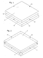
- Fig. 1 is a perspective view of a modular panel according to the invention which has a simple circumferentially connected by overlapping flange connectable.
- Fig. 2 is a perspective view of a modular panel according to the invention which has a circumferentially surrounding connectable by mutual engagement flange.
- Fig. 3 shows a perspective view of a part of a modular panel according to the invention which has a corresponding Ausschmiegung laterally in the region of the projecting pipe ends of the embedded in the panel heating / cooling pipe.
- Fig. 4 shows a cross-section through a modular panel according to the invention of the type shown in Fig. 2, the sectional plane being along one of the sections of the tube forming the panel forming the ends of which protrude to the underside of the panel.
- Fig. 5 shows partly in section the detail of the distance to the screed laid by U-profiles modular panels according to the invention, the connection of the two adjacent panels via simple circumferential circumferential flanges which overlap and are fastened by means of screw or pin, the connection between the pipe ends of the two panels takes place in the region of the distance profile, the space between screed and panels is filled by heat-insulating material.
- said modular panels are pritzen a mass of the type for the production of subfloors and thus mainly of inert material, cementitious and / or synthetic binder, from possible aggregates and fillers which improve the mechanical and / or thermally conductive properties of the material produced ; however, it does not preclude the use of blends of synthetic resins blended with granules of recycled plastics.
- the mechanical strength and the dimensional stability of the panels can be determined by fiber elements (glass fiber, Carbon fibers) or by wire-shaped elements (pieces of wire made of metal or plastic) which are interspersed in the mixture and / or improved by a single-layer or double-layered grid or grid-like reinforcement 3 or by a reinforcement of stretched, punched or perforated and deep-drawn sheet.
- the pipe 2 embedded in the mass forming the panel may be used for the passage of the heating or cooling medium thereon and / or fastened thereto by means of clamps or known clips 3a.
- the ends 2a of the tube 2 can protrude laterally (FIG. 3) or from the underside out of the panel 1 (FIGS. 4, 5). In the event that the ends 2a of the tube 2 project laterally, both of them can be arranged close to each other or spaced apart on the same side, on the panel extensions 1d can be provided in the corresponding area, it is not excluded that the individual ends protrude on different sides ,
- the connection between the pipe ends 2a against each other adjacent panels or between the pipe ends 2a and the flow and return pipes of the system are made by means of known coupling elements 6.
- the modular panel itself can be provided on the underside with a heat-insulating layer which can be applied after the manufacture of the panel or during its manufacturing phase by casting or by molding or which can be made by injecting a foaming plastic into the mold or into the mold ,
- the connecting flanges 1 a, 1 c which protrude circumferentially from the periphery of the modular panels 1 can have different shapes and different cross-sections in order to allow connection by simple overlapping (FIG. 5), the flanges can also have grooves or protruding ribs 1 c around a positive plug-in connection to build.
- the connection between the modular panels 1 can be secured by pins or screws 7 which on the circumferential flanges 1a, 1c in corresponding, provided with dowels or bushes, for example made of plastic, holes 1b are used.
- the invention does not exclude the use of adhesives, mortars or cementmilk to secure the connection between the panels 1, of course, expansion joints are provided by a certain clearance is provided between the panels in which eventually layers or seals of elastic material are used which Allow compensation movement between the laid panels 1.
- the modular panels 1 are laid on formed from metal profiles 5 grids which may be laid in a known manner on height-adjustable spacer feet which rest on the screed 8, the space between the panels 1 and the screed 8 for laying cables , Pipes, drains, air conditioning ducts and the like and / or used for laying a thermal barrier coating 4.
- the upper surface of the modular panels 1 according to the invention is suitable for the direct laying of any flooring, glued, anchored or floating type.
- the invention does not exclude that, in the case of a realized by pins or screws 7 connection between the connecting surfaces, a layer of elastic material is laid to compensate for any games and irregularities.
- the geometry of the connector may be formed such that angled surfaces are provided which favor an approximation between the composite panels.
Abstract
Description
Die Erfindung bezieht sich auf ein tragendes ausgeformtes modulares Element, welches ein Rohr für den Durchfluss eines Heiz- oder Kühlmediums enthält, wobei dieses Element mit anderen wesentlich identischen Elementen seitlich anbaubar und verbindbar ist um durch zweckmäßige Verbindung der inneren Rohre, bzw. durch Anschluss an die Vorlauf- und Rücklaufrohre eine Fußbodenheizung zu schaffen welche für unterschiedliche Arten von Bodenbelägen und für die Schaffung der Dehnungsfugen vorgefertigt ist.The invention relates to a load-bearing molded modular element containing a tube for the flow of a heating or cooling medium, said element with other substantially identical elements laterally attachable and connectable by appropriate connection of the inner tubes, or by connection to the supply and return pipes to create a floor heating which is prefabricated for different types of floor coverings and for the creation of expansion joints.
Aus der
Aus der
Aus der
Aus dem IT-Patentansuchen VI2004A000069 ist ein Bauelement bekannt welches aus einem wärmeisolierendem vorgeformten Paneel besteht um Heizungs/Kühlrohre aufzunehmen auf welchem eine Abdeckung, bestehend aus mindestens einer Metallplatte mit Zwischenlage mindestens eines Polyethylenlaminates, vorgesehen. Diese Bauelemente haben den Nachteil dass sie wenig ausgesteift und stabil sind und somit wenig geeignet für eine zum Estrich beabstandete Verlegung sind, weiters erstreckt sich auch in diesem Fall der Rohrkreislauf über mehrere modulare Paneele wodurch eventuelle nachtägliche Änderungen erschwert werden.From the IT patent application VI2004A000069 a device is known which consists of a heat-insulating preformed panel to accommodate heating / cooling tubes on which a cover consisting of at least one metal plate with intermediate layer of at least one polyethylene laminate provided. These components have the disadvantage that they are less stiffened and stable and thus are not very suitable for a screed spaced installation, further extends in this case, the pipe cycle over several modular panels whereby any nighttime changes are difficult.
Aus dem IT-Patentansuchen MI2004A002423 ist ein Bauelement für Fußböden bekannt welches wesentlich aus einer Wanne besteht welche ein Füllmaterial mit einem plattenförmigen Armierungselement enthält und einen Deckel aufweist. Diese paneelartigen Bauelemente sind ausschließlich für eine zum Estrich beabstandete Verlegung geeignet, sie werden in eine steife, gitterförmige Struktur aus Profilen verlegt welche auf einstellbaren Abstandsfüßen befestigt sind, dabei entstehen um jedes Element umlaufende Dehnungsfugen, weiters ist die Herstellung dieser Bauelemente relativ aufwändig.From the IT patent application MI2004A002423 a construction element for floors is known which essentially consists of a tub which contains a filling material with a plate-shaped reinforcing element and has a lid. These panel-like components are only suitable for a screed spaced installation, they are laid in a rigid, latticed structure of profiles which are mounted on adjustable spacer feet, thereby arise around each element circumferential expansion joints, further, the production of these components is relatively expensive.
Die Erfindung stellt sich die Aufgabe ein Bauelement der vorher beschriebenen Art zu schaffen welches für den Bau von Fußböden mit Fußbodenheizung geeignet ist, eine steife und formstabile Struktur hat, einfach zusammenbaubar ist, zeitsparend unter Verwertung von inertem oder wiederverwertetem, preisgünstigem Werkstoff herstellbar ist, mühelos sei es direkt auf dem Estrich oder vom Estrich beabstandet auf eigener Trägerstruktur verlegbar ist, wobei weiters, nach erfolgtem Verlegen, die einfache Abmontage einzelner Bauelemente und Eingriffe am Rohrkreislauf möglich sind.The invention has as its object to provide a device of the type described above which is suitable for the construction of floors with underfloor heating, has a rigid and dimensionally stable structure, is easy to assemble, time-saving under utilization of inert or recycled, low-cost material can be produced effortlessly be it directly on the screed or screed spaced on its own support structure can be laid, which further, after installation, the simple dismantling of individual components and interventions on the pipe circuit are possible.
Zur Lösung dieser Aufgabe schlägt die Erfindung ein Bauelement vor welches wesentlich aus einem Gemisch aus inertem Werkstoff mit zementartigem oder synthetischem Bindemittel oder aus einem Gemisch eines Granulats aus wiederverwertetem Kunststoff und aus synthetischen Kunstharzen, hergestellt wird; diese Gemische können in eine Form gegossen oder gespritzt werden aus welcher sie, nach Aushärtung, entformt werden. Vor dem Giesen oder Einspritzen der Masse in die Form, kann diese mit einer, z.B. metallischen, Bewehrung versehen werden an welcher das Heiz-/Kühlrohr gehalten wird. Diese Bewehrung samt Rohr wird in die Masse welche das Paneel bildet eingegossen, dabei ragen die Rohrenden unterhalb oder seitlich aus dem modularen Paneel hervor.To achieve this object, the invention proposes a device which is essentially made of a mixture of inert material with cementitious or synthetic binder or a mixture of granules of recycled plastic and synthetic resins; These mixtures can be poured or injected into a mold from which they are removed from the mold after hardening. Before pouring or injecting the mass into the mold, it may be filled with a, e.g. Metallic, provided reinforcement to which the heating / cooling tube is held. This reinforcement together with the pipe is poured into the mass which forms the panel, while the pipe ends project below or laterally out of the modular panel.
Erfindungsgemäß weist das modulare Paneel einen einfachen oder ausgeformten Flansch auf welcher am Umfang vorsteht und geeignet ist eine Verbindung durch Überlagerung oder Eingreifen am entsprechenden Flansch des anliegenden Paneels herzustellen. Diese Verbindung kann durch Zapfen oder Schrauben gesichert sein welche in entsprechende, eventuell mit Dübel oder Buchsen ausgestattete, Bohrungen eingesetzt sind, diese Bohrungen sind an den vorspringenden Flanschen in übereinstimmenden Positionen vorgesehen, es ist weiters eine Verbindung unter den umlaufenden Flanschen mittels Kleber, Mörtel oder dünnflüssigem Zement möglich. Vorteilhafterweise haben die besagten Flanschen eine Stärke welche der Hälfte der Stärke des Paneels entspricht und bilden somit, zusammen mit dem aufliegenden oder eingehängten Flansch des anliegenden Paneels, die selbe Stärke der verbundenen Paneele.According to the invention, the modular panel has a simple or molded flange projecting on the circumference and adapted to make a connection by interference or engagement with the corresponding flange of the adjacent panel. This compound can be secured by pins or screws which are inserted into corresponding, possibly equipped with dowels or bushings, holes, these holes are provided on the projecting flanges in matching positions, it is also a compound under the circumferential flanges by means of adhesive, mortar or low-viscosity cement possible. Advantageously, said Flanges have a thickness which corresponds to half the thickness of the panel and thus, together with the overlying or hinged flange of the adjacent panel, the same strength of the connected panels.
Der auf diese Weise zusammengesetzte Fußboden ist über seine gesamte Fläche formstabil auch wenn die einzelnen Paneele nicht mit ihrer gesamten unteren Fläche oder dem entsprechenden Umfangsbereich auf dem Estrich aufliegen. Die Erfindung schließt jedoch nicht aus dass, umlaufend entlang dem Umfang der Paneele, Nuten vorgesehen sind in welche entsprechende Federn eingesetzt werden können; in diesem Fall werden die Paneele einfach durch seitliches Zusammenschieben verbunden.The composite in this way floor is dimensionally stable over its entire surface even if the individual panels do not rest with their entire lower surface or the corresponding peripheral area on the screed. However, the invention does not exclude that, circumferentially along the periphery of the panels, grooves are provided in which corresponding springs can be used; In this case, the panels are simply connected by lateral pushing together.
Die Verbindung der Rohre der einzelnen modularen Paneele kann im seitlichen Verbindungsbereich der Paneele erfolgen indem im Bereich der seitlich vorstehenden Rohrenden Ausschmiegungen vorgesehen sind. Insbesondere im Fall einer vom Estrich distanzierten Verlegung der Paneele kann die Verbindung der Rohre an der Unterseite im Zwischenraum erfolgen; in diesem Fall ragen die Rohrenden an der Unterseite der Paneele hervor.The connection of the tubes of the individual modular panels can be done in the lateral connection region of the panels by Ausschmiegungen are provided in the region of the laterally projecting tube ends. In particular, in the case of a distance from the screed laying the panels, the connection of the tubes can be done on the bottom in the space; In this case, the pipe ends protrude from the underside of the panels.
Das Verlegen der erfindungsgemäßen Paneele kann auf einer gitterartigen Struktur aus vorher direkt auf dem Estrich verlegten Profilen erfolgen, ohne auszuschließen dass die besagte Gitterstruktur auf bekannten höhenverstellbaren, auf dem Estrich aufgestellten, Abstandsfüßen verlegt sein kann. Der durch diese bekannte Verlegeart gebildete Zwischenraum kann auf bekannte Weise z.B. für die Verlegung von Kabel, Rohre und/oder Kanäle genutzt werden.The laying of the panels according to the invention can be carried out on a lattice-like structure of previously laid directly on the screed profiles, without precluding that the said grid structure can be laid on known height-adjustable, set up on the screed, spacer feet. The gap formed by this known type of laying can be made in known manner, e.g. used for the laying of cables, pipes and / or ducts.
Die erfindungsgemäßen Paneele bilden eine Grundstruktur welche für das Verlegen jeglicher Art von Bodenbelag geeignet ist, die Dehnungsfugen sind einfach realisierbar indem im Bereich der Verbindungsfugen zwischen den modularen Paneelen das erforderliche Spiel vorgesehen wird ohne eine gegenseitige Verankerung der Paneele auszuführen. Zwischen den gegenseitigen Auflageflächen der umfangseitig abstehenden Flanschen der modularen Paneele können Schichten oder Dichtungen aus elastischen Werkstoff eingesetzt werden. Die Bewehrung des erfindungsgemäßen Paneels kann gitterförmig oder rostartig sein oder aus einem ausgeformten Blech bestehen, die besagten Bewehrungen können so ausgeführt sein dass sie das Rohr mit oder ohne Verwendung von Befestigungsklips oder Schellen aufnehmen; es wird nicht ausgeschlossen die Funktionstüchtigkeit der Bewehrung durch bekannte in das, das Paneel bildende, Gemisch vor dem Guss eingearbeitete faser- oder drahtförmige Werkstoffe zu ersetzen oder zu unterstützen.The panels of the invention form a basic structure which is suitable for laying any type of flooring, the expansion joints are easy to implement by the required clearance is provided in the joints between the modular panels without a mutual anchoring of the panels. Between the mutual Bearing surfaces of the circumferentially protruding flanges of the modular panels layers or seals made of elastic material can be used. The reinforcement of the panel according to the invention may be latticed or rust-like or consist of a shaped sheet metal, the said reinforcements may be designed to receive the pipe with or without the use of fastening clips or clamps; it is not excluded that the functionality of the reinforcement should be replaced or assisted by known fiber or wire materials incorporated into the panel forming mixture prior to casting.
Um die Ränder und/oder die Kanten und/oder jene Bereiche welche besonderen Belastungen ausgesetzt sind zu verstärken, kann das Paneel in den entsprechenden Bereichen mit Verstärkungsprofilen, Gitter oder Verstärkungsblechen versehen sein.In order to reinforce the edges and / or the edges and / or those areas which are subjected to particular stresses, the panel may be provided in the corresponding areas with reinforcing profiles, grids or reinforcing plates.
Die Unterseite des modularen Paneels kann nachträglich mit einer wärmedämmenden Schicht versehen werden, ohne dass ausgeschlossen wird dass diese Schicht in der Guss- oder Spritzphase angebracht wird indem sie in die Form eingelegt wird oder durch Einspritzen eines aufschäumenden Kunststoffes erzeugt wird.The underside of the modular panel can be subsequently provided with a heat-insulating layer, without it being ruled out that this layer is applied in the casting or injection phase by being inserted into the mold or by injecting a foaming plastic is generated.
Die Erfindung wird anschließend anhand einiger in den beigelegten Zeichnungen schematisch dargestellter erfindungsgemäßer modularer Paneele näher erklärt, dabei erfüllen die Zeichnungen rein erklärenden, nicht begrenzenden Zweck.The invention will be explained in more detail with reference to some schematically illustrated in the accompanying drawings modular panels according to the invention, the drawings meet purely explanatory, non-limiting purpose.
Die Fig. 1 ist eine perspektivische Darstellung eines modularen erfindungsgemäßen Paneels welches einen einfachen am Umfang umlaufenden durch Überlappung verbindbaren Flansch aufweist.Fig. 1 is a perspective view of a modular panel according to the invention which has a simple circumferentially connected by overlapping flange connectable.
Die Fig. 2 ist eine perspektivische Darstellung eines modularen erfindungsgemäßen Paneels welches einen am Umfang umlaufenden durch gegenseitiges Eingreifen verbindbaren Flansch aufweist.Fig. 2 is a perspective view of a modular panel according to the invention which has a circumferentially surrounding connectable by mutual engagement flange.
Die Fig. 3 zeigt in perspektivischer Darstellung einen Teil eines erfindungsgemäßen modularen Paneels welches seitlich im Bereich der vorstehenden Rohrenden des im Paneel eingebetteten Heizungs-/Kühlrohres eine entsprechende Ausschmiegung aufweist.Fig. 3 shows a perspective view of a part of a modular panel according to the invention which has a corresponding Ausschmiegung laterally in the region of the projecting pipe ends of the embedded in the panel heating / cooling pipe.
Die Fig. 4 zeigt einen Querschnitt durch ein erfindungsgemäßes modulares Paneel von der in Fig. 2 dargestellten Art, die Schnittebene verläuft entlang einem der Abschnitte des in die, das Paneel bildende, Masse eingebettete Rohres dessen Enden an der Unterseite des Paneels vorstehen.Fig. 4 shows a cross-section through a modular panel according to the invention of the type shown in Fig. 2, the sectional plane being along one of the sections of the tube forming the panel forming the ends of which protrude to the underside of the panel.
Die Fig. 5 zeigt teilweise im Schnitt das Detail der mit Abstand zum Estrich mittels U-Profile verlegten erfindungsgemäßen modularen Paneele, die Verbindung der zwei anliegenden Paneele erfolgt über einfache am Umfang umlaufende Flanschen welche sich überlappen und mittels Schraube oder Zapfen befestigt sind, die Verbindung zwischen den Rohrenden der beiden Paneele erfolgt im Bereich des Abstandsprofils, der Zwischenraum zwischen Estrich und Paneele ist von wärmedämmendem Material ausgefüllt.Fig. 5 shows partly in section the detail of the distance to the screed laid by U-profiles modular panels according to the invention, the connection of the two adjacent panels via simple circumferential circumferential flanges which overlap and are fastened by means of screw or pin, the connection between the pipe ends of the two panels takes place in the region of the distance profile, the space between screed and panels is filled by heat-insulating material.
Die modularen Paneele 1 für die Schaffung eines Fußbodens mit Fußbodenheizung, welcher direkt auf den Estrich 8 verlegt ist oder in distanzierter Position auf einer Roststruktur aus Abstandsprofilen 5 welche gegebenenfalls auf höhenverstellbaren bekannten Füßen aufliegen, verlegt ist, haben vorzugsweise quadratische oder rechteckige Form. Erfindungsgemäß sind die besagten modularen Paneele pritzen einer Masse von der Art zur Herstellung von Unterböden und somit vorwiegend aus inertem Material, aus zementartigem und/oder synthetischem Bindemittel , aus eventuellen Zuschlägen und Füller welche die mechanischen und/oder die wärmeleitenden Eigenschaften des Werkstoffes verbessern, hergestellt; es wird jedoch nicht der Einsatz von Mischungen aus synthetischen Harzen vermengt mit Granulaten aus wiederverwerteten Kunststoffen ausgeschlossen. Die mechanische Festigkeit und die Formstabilität der Paneele können durch Faserelemente (Glasfaser, Kohlenstofffasern) oder durch drahtförmige Elemente (Drahtstücke aus Metall oder aus Kunststoff) welche in das Gemisch eingestreut sind und/oder durch eine einlagige oder doppellagige rost- oder gitterartige Bewehrung 3 oder durch eine Bewehrung aus gestrecktem, ausgestanztem oder gelochtem und tiefgezogenem Blech verbessert werden. Im Falle einer Bewehrung kann das in die, das Paneel bildende, Masse eingebettete Rohr 2 für den Durchfluss des Heiz- oder Kühlmittels an dieser eingesetzt und/oder an dieser mittels Schellen oder bekannter Klips 3a befestigt sein.The
Die Enden 2a des Rohres 2 können seitlich (Fig. 3) oder von der Unterseite aus dem Paneel 1 ragen (Fig. 4, 5). Im Falle dass die Enden 2a des Rohres 2 seitlich hervorragen, können diese beide an der selben Seite nahe nebeneinander oder voneinander distanziert angeordnet sein, am Paneel können im entsprechenden Bereich Ausschmiegungen 1d vorgesehen sein, es wird nicht ausgeschlossen dass die einzelnen Enden an unterschiedlichen Seiten hervorragen. Die Verbindung zwischen den Rohrenden 2a gegeneinander anliegender Paneele oder zwischen den Rohrenden 2a und den Vorlauf- und Rücklaufrohren der Anlage, sind mittels bekannter Kupplungselemente 6 hergestellt.The
Das modulare Paneel selbst kann an der Unterseite mit einer wärmedämmenden Schicht versehen sein welche nach der Fertigung des Paneels oder während dessen Fertigungsphase durch Gießen oder durch Formpressen angebracht werden kann oder welche durch Einspritzen eines aufschäumenden Kunststoffes in die Gussform oder in die Pressform, gefertigt werden kann.The modular panel itself can be provided on the underside with a heat-insulating layer which can be applied after the manufacture of the panel or during its manufacturing phase by casting or by molding or which can be made by injecting a foaming plastic into the mold or into the mold ,
Die Verbindungsflanschen 1a, 1c welche umlaufend vom Umfang der modularen Paneele 1 abstehen können erfindungsgemäß unterschiedliche Form und unterschiedlichen Querschnitt aufweisen um eine Verbindung durch einfache Überlappung (Fig. 5) zu ermöglichen, die Flanschen können auch Rillen oder vorstehende Rippen 1c aufweisen um eine formschlüssige Steckverbindung zu bilden. Die Verbindung zwischen den modularen Paneelen 1 kann durch Zapfen oder Schrauben 7 gesichert werden welche an den umlaufenden Flanschen 1a, 1c in entsprechende, mit Dübel oder Buchsen z.B. aus Kunststoff versehene, Bohrungen 1b eingesetzt sind.According to the invention, the connecting
Die Erfindung schließt nicht die Anwendung von Klebern, Mörtel oder Zementmilch aus um die Verbindung zwischen den Paneelen 1 zu sichern, wobei natürlich Dehnungsfugen vorgesehen werden indem zwischen den Paneelen ein gewisses Spiel vorgesehen ist in welches eventuell Schichten oder Dichtungen aus elastischem Werkstoff eingesetzt werden welche eine Ausgleichbewegung zwischen den verlegten Paneelen 1 ermöglichen.The invention does not exclude the use of adhesives, mortars or cementmilk to secure the connection between the
Im Falle dass die modularen Paneele 1 auf, aus Metallprofilen 5 gebildeten Roste verlegt werden welche eventuell auf bekannte Art auf höhenverstellbaren Abstandsfüßen welche auf dem Estrich 8 aufliegen, verlegt werden, kann der Zwischenraum zwischen den Paneelen 1 und dem Estrich 8 für das Verlegen von Kabel, Rohre, Abflüsse, Klimatisierungskanäle und dergleichen und/oder für das Verlegen einer Wärmedämmschicht 4 genutzt werden.In the case that the
Die obere Fläche der modularen Paneele 1 ist erfindungsgemäß für das direkte Verlegen jedes beliebigen Bodenbelages, von der aufgeklebten, von der verankerten oder von der schwimmenden Art, geeignet.The upper surface of the
Die Erfindung schließt nicht aus dass, im Falle einer durch Zapfen oder Schrauben 7 realisierten Verbindung, zwischen den Verbindungsflächen eine Schicht elastischen Werkstoffes verlegt wird um eventuelle Spiele und Unregelmäßigkeiten auszugleichen. Im Falle der formschlüssigen Verbindung zwischen den umlaufenden Flanschen, kann die Geometrie der Steckverbindung derart ausgebildet sein dass angewinkelte Flächen vorgesehen sind welche ein Annähern zwischen den zusammengesetzten Paneelen begünstigen.The invention does not exclude that, in the case of a realized by pins or
Eventuell können auf dem, aus zusammengesetzten modularen erfindungsgemäßen Paneelen zusammengesetzten Boden, vor dem Verlegen des Bodenbelages, bekannte Produkte, z.B. der selbstnivellierenden Art welche mit dem, die Paneele bildenden, Werkstoff ausgezeichnet binden, ausgebracht werden.Possibly, on the composite of composite modular panels according to the invention prior to laying the floor covering, known products, such as the self-leveling type which with the, forming the panels forming material excellent bind, be applied.
Claims (10)
Applications Claiming Priority (1)
| Application Number | Priority Date | Filing Date | Title |
|---|---|---|---|
| IT000044A ITBZ20060044A1 (en) | 2006-10-25 | 2006-10-25 | MODULAR PANEL FOR THE CONSTRUCTION OF RADIANT PANELS |
Publications (2)
| Publication Number | Publication Date |
|---|---|
| EP1916483A2 true EP1916483A2 (en) | 2008-04-30 |
| EP1916483A3 EP1916483A3 (en) | 2013-04-10 |
Family
ID=39047610
Family Applications (1)
| Application Number | Title | Priority Date | Filing Date |
|---|---|---|---|
| EP07019534.2A Withdrawn EP1916483A3 (en) | 2006-10-25 | 2007-10-05 | Modular panel for underfloor heating |
Country Status (2)
| Country | Link |
|---|---|
| EP (1) | EP1916483A3 (en) |
| IT (1) | ITBZ20060044A1 (en) |
Cited By (5)
| Publication number | Priority date | Publication date | Assignee | Title |
|---|---|---|---|---|
| JP2009544873A (en) * | 2006-07-28 | 2009-12-17 | ヴォルカン,アルベルト | Solar panels, especially tiles |
| ES2383865A1 (en) * | 2012-03-08 | 2012-06-27 | Anguiano Poliuretanos, S.L. | Decorative radiator with integrated water circuit |
| DE102011000079A1 (en) * | 2011-01-11 | 2012-07-12 | Höppner Andrea | Structure plate i.e. moisture-permeable structure plate, for modularly configured surface temperature system during renovation work in old-building, has circle and/or ellipsoidal structural elements and/or structural element portions |
| ITTO20130862A1 (en) * | 2013-10-24 | 2015-04-25 | Ennetiesse Srl | RAISED FLOORING AND THERMOREGULATED PREFABRICATED ELEMENTS |
| US11569661B2 (en) | 2021-01-11 | 2023-01-31 | Watlow Electric Manufacturing Company | Masterless distributed dynamic load management |
Citations (3)
| Publication number | Priority date | Publication date | Assignee | Title |
|---|---|---|---|---|
| DE3425019A1 (en) * | 1984-07-06 | 1986-01-30 | Marbeton Kies- U. Betonwerk Marstetten Gmbh, 7971 Aitrach | Floor slab for a propped-up floor and a floor formed from floor slabs of this type |
| EP0886109A2 (en) * | 1997-06-16 | 1998-12-23 | Nägelebau GmbH & Co. | Method of operating an underfloor heating and means to carry out this method |
| WO2006064531A1 (en) * | 2004-12-17 | 2006-06-22 | Natale Quaglia | Floor panel and floor |
-
2006
- 2006-10-25 IT IT000044A patent/ITBZ20060044A1/en unknown
-
2007
- 2007-10-05 EP EP07019534.2A patent/EP1916483A3/en not_active Withdrawn
Patent Citations (3)
| Publication number | Priority date | Publication date | Assignee | Title |
|---|---|---|---|---|
| DE3425019A1 (en) * | 1984-07-06 | 1986-01-30 | Marbeton Kies- U. Betonwerk Marstetten Gmbh, 7971 Aitrach | Floor slab for a propped-up floor and a floor formed from floor slabs of this type |
| EP0886109A2 (en) * | 1997-06-16 | 1998-12-23 | Nägelebau GmbH & Co. | Method of operating an underfloor heating and means to carry out this method |
| WO2006064531A1 (en) * | 2004-12-17 | 2006-06-22 | Natale Quaglia | Floor panel and floor |
Non-Patent Citations (1)
| Title |
|---|
| "Beton", , 6. Juni 2004 (2004-06-06), XP055054743, Gefunden im Internet: URL:http://de.wikipedia.org/w/index.php?title=Beton&oldid=1452548 [gefunden am 2013-02-27] * |
Cited By (5)
| Publication number | Priority date | Publication date | Assignee | Title |
|---|---|---|---|---|
| JP2009544873A (en) * | 2006-07-28 | 2009-12-17 | ヴォルカン,アルベルト | Solar panels, especially tiles |
| DE102011000079A1 (en) * | 2011-01-11 | 2012-07-12 | Höppner Andrea | Structure plate i.e. moisture-permeable structure plate, for modularly configured surface temperature system during renovation work in old-building, has circle and/or ellipsoidal structural elements and/or structural element portions |
| ES2383865A1 (en) * | 2012-03-08 | 2012-06-27 | Anguiano Poliuretanos, S.L. | Decorative radiator with integrated water circuit |
| ITTO20130862A1 (en) * | 2013-10-24 | 2015-04-25 | Ennetiesse Srl | RAISED FLOORING AND THERMOREGULATED PREFABRICATED ELEMENTS |
| US11569661B2 (en) | 2021-01-11 | 2023-01-31 | Watlow Electric Manufacturing Company | Masterless distributed dynamic load management |
Also Published As
| Publication number | Publication date |
|---|---|
| EP1916483A3 (en) | 2013-04-10 |
| ITBZ20060044A1 (en) | 2008-04-26 |
Similar Documents
| Publication | Publication Date | Title |
|---|---|---|
| WO2002031290A1 (en) | Tile | |
| DE2352779A1 (en) | PANEL ELEMENT FOR A PRE-FABRICATED BUILDING AND SUCH A BUILDING | |
| EP2397322B1 (en) | Construction board with embedded pipeline conduit for a heating or cooling fluid | |
| WO2004008032A1 (en) | Method for producing heat exchanger elements, heat exchanger elements and method for assembling such elements | |
| DE60314459T2 (en) | CONSTRUCTION ELEMENT FOR CABINET CONSTRUCTION | |
| EP1916483A2 (en) | Modular panel for underfloor heating | |
| DE202006015397U1 (en) | Multilayer structure system e.g. for flooring of underfloor heating, has under and lateral plate formed construction unit for admission of pipes of under-floor heating and on surface of plate construction unit uncoupling mat is arranged | |
| DE19947349B4 (en) | Floor plate for animal husbandry and method of making the same | |
| EP0112272A2 (en) | Element and method of manufacturing said element | |
| CH617999A5 (en) | Plate-shaped structural element for radiant heating systems | |
| EP0655585B1 (en) | Heating element | |
| DE2361137A1 (en) | PREFABRICATED COMPONENT | |
| EP0464164B1 (en) | Prefabricated tile for an underfloor-air-conditioning system | |
| DE19920081C2 (en) | Wall element for a building and method for producing such a wall element | |
| DE19737097A1 (en) | Equipment to form balcony floor | |
| EP2927383A1 (en) | Formwork for walls which are to be built | |
| AT510162B1 (en) | FLOOR HEATING AND / OR COOLING SYSTEM | |
| DE19963984C2 (en) | Foundation for buildings, in particular for buildings | |
| DE202008005910U1 (en) | Mounting plate for fixing heating pipes | |
| DE102004034707A1 (en) | Core heating and hardening module for concrete slab is laid on top of reinforcement bars held on spacers in standard production pallet and consists of pipe in meandering arrangement | |
| DE3400483A1 (en) | Sandwich heat exchanger | |
| DE102010036439A1 (en) | Surface heating/cooling system for heating/cooling e.g. floor, has surface heating/cooling modules each including heat-conducting upper layer connected with heat-insulating lower layer by integrated heat-conducting carrier pipe | |
| EP2574852A2 (en) | Method for producing large-scale floor heating systems and floor heating systems produced according to this method | |
| WO2018132850A1 (en) | Floor | |
| DE20316204U1 (en) | Reinforcement arrangement for rigid, highly loadable surface coverings on flat surfaces, in particular for tile or tile coverings |
Legal Events
| Date | Code | Title | Description |
|---|---|---|---|
| PUAI | Public reference made under article 153(3) epc to a published international application that has entered the european phase |
Free format text: ORIGINAL CODE: 0009012 |
|
| AK | Designated contracting states |
Kind code of ref document: A2 Designated state(s): AT BE BG CH CY CZ DE DK EE ES FI FR GB GR HU IE IS IT LI LT LU LV MC MT NL PL PT RO SE SI SK TR |
|
| AX | Request for extension of the european patent |
Extension state: AL BA HR MK RS |
|
| PUAL | Search report despatched |
Free format text: ORIGINAL CODE: 0009013 |
|
| AK | Designated contracting states |
Kind code of ref document: A3 Designated state(s): AT BE BG CH CY CZ DE DK EE ES FI FR GB GR HU IE IS IT LI LT LU LV MC MT NL PL PT RO SE SI SK TR |
|
| AX | Request for extension of the european patent |
Extension state: AL BA HR MK RS |
|
| RIC1 | Information provided on ipc code assigned before grant |
Ipc: F24D 3/14 20060101ALI20130305BHEP Ipc: F24D 3/12 20060101ALI20130305BHEP Ipc: E04F 15/024 20060101ALI20130305BHEP Ipc: F24D 3/16 20060101AFI20130305BHEP |
|
| AKX | Designation fees paid |
Designated state(s): AT BE BG CH CY CZ DE DK EE ES FI FR GB GR HU IE IS IT LI LT LU LV MC MT NL PL PT RO SE SI SK TR |
|
| AXX | Extension fees paid |
Extension state: AL Payment date: 20071004 Extension state: BA Payment date: 20071004 Extension state: MK Payment date: 20071004 Extension state: HR Payment date: 20071004 Extension state: RS Payment date: 20071004 |
|
| STAA | Information on the status of an ep patent application or granted ep patent |
Free format text: STATUS: THE APPLICATION IS DEEMED TO BE WITHDRAWN |
|
| 18D | Application deemed to be withdrawn |
Effective date: 20131011 |