EP1916369A1 - Charnière à rappel automatique - Google Patents
Charnière à rappel automatique Download PDFInfo
- Publication number
- EP1916369A1 EP1916369A1 EP07119047A EP07119047A EP1916369A1 EP 1916369 A1 EP1916369 A1 EP 1916369A1 EP 07119047 A EP07119047 A EP 07119047A EP 07119047 A EP07119047 A EP 07119047A EP 1916369 A1 EP1916369 A1 EP 1916369A1
- Authority
- EP
- European Patent Office
- Prior art keywords
- piston
- hinge according
- plate
- flat
- hinge
- Prior art date
- Legal status (The legal status is an assumption and is not a legal conclusion. Google has not performed a legal analysis and makes no representation as to the accuracy of the status listed.)
- Granted
Links
Images

Classifications
-
- E—FIXED CONSTRUCTIONS
- E05—LOCKS; KEYS; WINDOW OR DOOR FITTINGS; SAFES
- E05D—HINGES OR SUSPENSION DEVICES FOR DOORS, WINDOWS OR WINGS
- E05D11/00—Additional features or accessories of hinges
- E05D11/10—Devices for preventing movement between relatively-movable hinge parts
- E05D11/1014—Devices for preventing movement between relatively-movable hinge parts for maintaining the hinge in only one position, e.g. closed
-
- E—FIXED CONSTRUCTIONS
- E05—LOCKS; KEYS; WINDOW OR DOOR FITTINGS; SAFES
- E05F—DEVICES FOR MOVING WINGS INTO OPEN OR CLOSED POSITION; CHECKS FOR WINGS; WING FITTINGS NOT OTHERWISE PROVIDED FOR, CONCERNED WITH THE FUNCTIONING OF THE WING
- E05F1/00—Closers or openers for wings, not otherwise provided for in this subclass
- E05F1/08—Closers or openers for wings, not otherwise provided for in this subclass spring-actuated, e.g. for horizontally sliding wings
- E05F1/10—Closers or openers for wings, not otherwise provided for in this subclass spring-actuated, e.g. for horizontally sliding wings for swinging wings, e.g. counterbalance
- E05F1/12—Mechanisms in the shape of hinges or pivots, operated by springs
- E05F1/1246—Mechanisms in the shape of hinges or pivots, operated by springs with a coil spring perpendicular to the pivot axis
- E05F1/1253—Mechanisms in the shape of hinges or pivots, operated by springs with a coil spring perpendicular to the pivot axis with a compression spring
-
- E—FIXED CONSTRUCTIONS
- E05—LOCKS; KEYS; WINDOW OR DOOR FITTINGS; SAFES
- E05D—HINGES OR SUSPENSION DEVICES FOR DOORS, WINDOWS OR WINGS
- E05D5/00—Construction of single parts, e.g. the parts for attachment
- E05D5/02—Parts for attachment, e.g. flaps
- E05D5/0246—Parts for attachment, e.g. flaps for attachment to glass panels
-
- E—FIXED CONSTRUCTIONS
- E05—LOCKS; KEYS; WINDOW OR DOOR FITTINGS; SAFES
- E05D—HINGES OR SUSPENSION DEVICES FOR DOORS, WINDOWS OR WINGS
- E05D5/00—Construction of single parts, e.g. the parts for attachment
- E05D5/10—Pins, sockets or sleeves; Removable pins
- E05D5/12—Securing pins in sockets, movably or not
- E05D5/128—Securing pins in sockets, movably or not the pin having a recess or through-hole engaged by a securing member
-
- E—FIXED CONSTRUCTIONS
- E05—LOCKS; KEYS; WINDOW OR DOOR FITTINGS; SAFES
- E05Y—INDEXING SCHEME ASSOCIATED WITH SUBCLASSES E05D AND E05F, RELATING TO CONSTRUCTION ELEMENTS, ELECTRIC CONTROL, POWER SUPPLY, POWER SIGNAL OR TRANSMISSION, USER INTERFACES, MOUNTING OR COUPLING, DETAILS, ACCESSORIES, AUXILIARY OPERATIONS NOT OTHERWISE PROVIDED FOR, APPLICATION THEREOF
- E05Y2900/00—Application of doors, windows, wings or fittings thereof
- E05Y2900/10—Application of doors, windows, wings or fittings thereof for buildings or parts thereof
- E05Y2900/13—Type of wing
- E05Y2900/132—Doors
Definitions
- the invention relates to a self-return hinge, particularly designed to be mounted on the edge of a panel, including a glass panel such as that of a shower door.
- a hinged glass door is known, supported by self-retracting hinges designed to automatically place the door in at least one predetermined position, including a closed position.
- the patent FR-76 05 743 belonging to the applicant, describes a hinge of this kind in which the return is obtained by action of a flat tip piston, biased by springs to a cam.
- the springs are mounted on a portion of the hinge attached to the glass plate.
- the cam is integral with the other part.
- One of the aims of the invention is to solve this problem.
- the invention relates to a self-return hinge comprising two plates articulated to each other, a first plate carrying two arms forming a yoke and a second plate carrying a piston, a trunnion with at least one flat being fixed to said clevis and said piston being elastically biased towards said flattened trunnion, characterized in that said piston is metallic, in that said second plate comprises a first and a second guide block distant from each other between which said piston is slidably mounted and guided, in that said first guide block is located between the two arms of the yoke and houses said flattened journal, in that one end of said piston located inside said first guide block has a flat surface cooperating with said flat and in that said spring is mounted between a shoulder of said piston and said second guide block.
- At least the flat surface of the piston which cooperates with the flat has undergone a curing treatment. This increases the service life of the hinge and, above all, it maintains an automatic closing position chosen and very constant over time.
- Another problem is that of sealing at the hinge itself.
- said first guide block comprises a rounded outer surface substantially coaxial with the axis of said flattened trunnion.
- first plate comprises a hollow with a substantially cylindrical surface facing said rounded outer surface, so as to define a curved laminar space, of small thickness and of a certain length between said first plate and said first guide block.
- Vent holes are drilled at the base of said screed arms.
- said recess and / or said substantially cylindrical surface are provided with a decompression groove.
- This adjustment stop is housed in a bore made in one of the arms of said yoke and a locking screw, engaged in a threaded portion of this bore urges the adjustment stop bearing against said flattened spigot.
- This adjustment stop may comprise a cylindrical portion provided with a bevelled surface.
- the beveled surface may be in the extension of a flat, facilitating the positioning of the abutment transversely to the trunnion.
- the hinge shown comprises two plates 12, 14 hinged to each other and a mounting plate 16 for covering the plate 14 to enclose a door panel, such as a glass panel 17.
- An indented cutout 18 is practiced in the glass panel along an edge thereof.
- the first plate 12 carries two arms 20, 22 forming a yoke, extending generally perpendicular to its plane. It also has two fixing holes. Two coaxial bores are made in the arms 20, 22.
- the bore 24 of the arm 20 has a greater diameter than the bore 26 of the arm 22, so that a flattened spigot 25 provided with a shoulder 27 corresponding to the difference in diameter of the bores, can be mounted between the arms of the yoke and attached thereto, as will be seen later.
- the second plate 14 carries a piston 28 which is resiliently biased towards said flattened pin.
- the second plate comprises a first and a second guide block 30, 32 spaced from each other and between which said piston 28 is mounted and guided in sliding.
- the first guide block 30 is, according to the example, molded with said second plate 14 near an edge thereof, and between two notches 36 in which engage the arms 20, 22 of the yoke.
- This guide block 30 comprises a bore 38 which houses said flattened spigot 25, more particularly the section thereof which comprises said flat 25a.
- the second guide block 32 is here fixed to the second plate 14. It has the general shape of a U whose parallel wings 40 come into contact with flats 42 made respectively along two columns 44 integral with said second plate 14.
- the posts allow the attachment of the mounting plate 16 to said second plate 14 while keeping it spaced therefrom so as to grip the glass panel 17.
- U-shaped flat seals 46 are interposed between the second plate 14 and the mounting plate 16 on the one hand and the glass panel 17, on the other hand.
- Two mounting screws 48 engaged in tapped holes 50 of the columns ensure the attachment of the second plate and the mounting plate on either side of the glass panel.
- Semi-cylindrical grooves 52, 53 are formed on the flats of the columns and on the parallel outer faces of the second guide block 32. In the mounting position, these grooves face each other in pairs to accommodate two pins 55 which immobilize the second guide block between the two balusters.
- the second guide block 14 is spaced from the first and comprises, on its base 57, perpendicular to the two flanges 40, a cylindrical hole 59 in which a portion of a rod 60 of the piston 28 slides.
- the other end of the piston comprises an enlarged head 62, here approximately rectangular contour and having a flat surface 64 perpendicular to the axis of the piston rod.
- This head is slidably mounted in a corresponding opening 66 of said first guide block, which opens into the bore 38 thereof.
- the flat surface 64 cooperates with the flattened portion 25a of the pin to define the closed position of the door.
- a spring 68 urges the piston towards the flattened pin. It is prestressedly mounted between a piston shoulder (defined between the rod and the head) and said second guide block 32, more particularly the base 57 thereof.
- the hinge is equipped with a single coil spring 68. More specifically, the spring 68 is engaged on the rod 60 of the piston, and preferably the diameter of this rod is substantially equal to the inner diameter of the spring. This ensures good spring guidance.
- the entire piston is monobloc and metallic.
- the flat surface 64 of the piston which cooperates with the flat has undergone a curing treatment of a known type, depending on the metal of which said piston is constituted.
- the stable position of closure of the door is adjustable as soon as the hinge is equipped with a fixed flat spigot 25.
- an adjustment stop 72 of the position of said pin 25 relative to the yoke is housed in a bore 74 formed in one of 22 arms of said yoke. This bore opens into the bore 26.
- a locking screw 76 engaged in a threaded portion of this bore, biases the position adjustment stop bearing against said flattened pin.
- the adjustment stop includes a cylindrical portion 78 provided with a bevelled surface 79. This beveled surface is extended by a flat surface 80.
- the bore opens out facing a groove 82 of the pin 25 so that the portion of the stop 78 having the flat part can engage in this groove.
- the mounted door is placed in the desired closed position.
- the piston head 62 is in contact with the flat 25a.
- the adjustment stop 72 is inserted into the bore 74 (for each hinge) so that the beveled portion 79 comes into contact with the cylindrical surface of the pin in the groove 82.
- the tightening of the screw 76 causes the locking of the pin in the yoke, under the action of said adjustment stop.
- said first guide block 30 has a rounded outer surface 80, substantially coaxial with the axis of said flanged spigot.
- the space between said rounded outer surface and the surface of said first plate 12 is constant regardless of the position of the hinge. This space can be as small as possible.
- said first plate comprises a hollow 82 with a substantially cylindrical surface facing said rounded outer surface 80 of the first guide block, so as to define a laminar space of small thickness, constant, d a certain length, between said first plate 12 and said first guide block 30.
- said recess and / or said substantially cylindrical surface of the guide block are provided with decompression grooves 86, 87 s extending between the two arms of the screed. Evacuation holes 89 are drilled at the base of said arms of the yoke.
- the fact that the piston is metallic makes it possible not only to avoid premature wear of the face 64 but also to avoid bending of the piston rod between its two guides, which also contributes to maintaining the Precision of the recall position, in time.
- first and second guide blocks are part of said second platen.
- this second plate can be obtained by molding, followed by a finishing machining of said guide blocks, enough simple to implement and ensuring good alignment accuracy of the piston guide bores.
Landscapes
- Engineering & Computer Science (AREA)
- Mechanical Engineering (AREA)
- Closing And Opening Devices For Wings, And Checks For Wings (AREA)
- Hinges (AREA)
- Holders For Sensitive Materials And Originals (AREA)
Abstract
Description
- L'invention se rapporte à une charnière à rappel automatique, plus particulièrement conçue pour être montée au bord d'un panneau, notamment un panneau de verre tel que celui d'une porte de douche.
- On connaît une porte en verre articulée, supportée par des charnières à rappel automatique conçues pour placer la porte automatiquement dans au moins une position prédéterminée, notamment une position de fermeture.
- Le brevet
FR-76 05 743 - Dans ce genre de charnière, on peut rencontrer certaines difficultés que l'invention se propose de surmonter.
- En premier lieu, il est souhaitable de garantir une position de fermeture de la porte qui soit bien déterminée et stable dans le temps, ce qui est essentiel pour l'étanchéité des cabines de douche, notamment depuis l'apparition des rampes d'hydromassage à jets horizontaux. Cette qualité dépend de la précision de la position de rappel, prédéterminée par le mécanisme décrit ci-dessus. Elle dépend aussi de la résistance à l'usure d'un tel mécanisme. A titre d'exemple, un rappel dont l'incertitude est de plus ou moins 3° entraîne une ouverture résiduelle de la porte de plus ou moins 40 mm environ, ce qui est insuffisant pour l'application envisagée.
- L'invention vise, entre autres à résoudre ce problème.
- Plus particulièrement, l'invention concerne une charnière à rappel automatique comportant deux platines articulées l'une à l'autre, une première platine portant deux bras formant chape et une seconde platine portant un piston, un tourillon à au moins un méplat étant fixé à ladite chape et ledit piston étant élastiquement sollicité vers ledit tourillon à méplat, caractérisée en ce que ledit piston est métallique, en ce que ladite seconde platine comporte un premier et un second bloc de guidage distants l'un de l'autre entre lesquels ledit piston est monté et guidé en coulissement, en ce que ledit premier bloc de guidage est situé entre les deux bras de la chape et abrite ledit tourillon à méplat, en ce qu'une extrémité dudit piston situé à l'intérieur de ce premier bloc de guidage comporte une surface plane coopérant avec ledit méplat et en ce que ledit ressort est monté entre un épaulement dudit piston et ledit second bloc de guidage.
- Avantageusement, au moins la surface plane du piston qui coopère avec le méplat a subi un traitement de durcissement. On augmente ainsi la durée de vie de la charnière et, surtout, on conserve une position de fermeture automatique choisie et bien constante dans le temps.
- Un autre problème est celui de l'étanchéité au niveau de la charnière elle-même.
- Selon une caractéristique avantageuse, ledit premier bloc de guidage comporte une surface extérieure arrondie, sensiblement coaxiale avec l'axe dudit tourillon à méplat.
- Ceci permet de garantir une distance aussi faible que possible entre ledit bloc de guidage et ladite première platine, sur toute la distance qui sépare les deux bras de la chape.
- Cette étanchéité peut encore être améliorée si ladite première platine comporte une creusure à surface sensiblement cylindrique faisant face à ladite surface extérieure arrondie, de façon à définir un espace laminaire courbe, de faible épaisseur et d'une certaine longueur entre ladite première platine et ledit premier bloc de guidage.
- Des trous d'évacuation sont percés à la base desdits bras de la chape.
- Avantageusement, ladite creusure et/ou ladite surface sensiblement cylindrique sont munies de gorge de décompression.
- Encore un autre problème est celui du réglage de la position de fermeture de la porte.
- Pour ce faire, on peut prévoir une butée de réglage de la position dudit tourillon à méplat par rapport à ladite chape. Cette butée de réglage est logée dans un perçage pratiqué dans l'un des bras de ladite chape et une vis de blocage, engagée dans une partie taraudée de ce perçage sollicite la butée de réglage en appui contre ledit tourillon à méplat.
- Cette butée de réglage peut comporter une partie cylindrique munie d'une surface biseautée.
- La surface biseautée peut être dans le prolongement d'un méplat, facilitant le positionnement de la butée transversalement au tourillon.
- L'invention sera mieux comprise et d'autres avantages apparaîtront plus clairement à la lumière de la description qui va suivre d'une charnière à rappel automatique conforme à son principe, donnée uniquement à titre d'exemple et faite en référence aux dessins annexés dans lesquels :
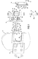
- la figure 1 est une vue en perspective éclatée d'une charnière conforme à l'invention ;
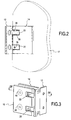
- la figure 2 représente une telle charnière associée à un panneau de verre ;
- la figure 3 est une vue en perspective de la charnière seule, vu de l'arrière de la figure 2 ;
- la figure 4 est une coupe IV-IV de la figure 3 ;
- la figure 5 est une vue en perspective de ladite première platine ; et
- la figure 6 est une vue de détail en perspective montrant la butée de réglage de position.
- La charnière représentée comporte deux platines 12, 14 articulées l'une à l'autre et une plaque de montage 16 destinée à recouvrir la platine 14 pour enserrer un panneau formant porte, tel qu'un panneau en verre 17. Une découpe échancrée 18 est pratiquée dans le panneau de verre le long d'un bord de celui-ci.
- La première platine 12 porte deux bras 20, 22 formant chape, s'étendant globalement perpendiculaire à son plan. Elle comporte aussi deux trous de fixation. Deux alésages coaxiaux sont pratiqués dans les bras 20, 22. L'alésage 24 du bras 20 a un diamètre plus grand que celui de l'alésage 26 du bras 22, de façon qu'un tourillon à méplat 25, muni d'un épaulement 27 correspondant à la différence de diamètre des alésages, puisse être monté entre les bras de la chape et fixé à celle-ci, comme on le verra plus loin.
- La seconde platine 14 porte un piston 28 qui est élastiquement sollicité vers ledit tourillon à méplat. De plus, la seconde platine comporte un premier et un second bloc de guidage 30, 32 distant l'un de l'autre et entre lesquels ledit piston 28 est monté et guidé en coulissement. Le premier bloc de guidage 30 est, selon l'exemple, venu de moulage avec ladite seconde platine 14 près d'un bord de celle-ci, et entre deux échancrures 36 dans lesquelles s'engagent les bras 20, 22 de la chape. Ce bloc de guidage 30 comporte un alésage 38 qui abrite ledit tourillon à méplat 25, plus particulièrement le tronçon de celui-ci qui comporte ledit méplat 25a. Après assemblage des deux platines 12, 14, ledit premier bloc de guidage 30 est situé entre les deux bras 20, 22 de la chape.
- Le second bloc de guidage 32 est ici fixé à la seconde platine 14. Il a la forme générale d'un U dont les ailes parallèles 40 viennent au contact de méplats 42 pratiqués respectivement le long de deux colonnettes 44 solidaires de ladite seconde platine 14. Les colonnettes permettent la fixation de la plaque de montage 16 à ladite seconde platine 14 tout en la maintenant espacée de celle-ci de façon à enserrer le panneau de verre 17. Des joints plats 46 en forme de U, par exemple en élastomère, sont intercalés entre la seconde platine 14 et la plaque de montage 16 d'une part et le panneau de verre 17, d'autre part. Deux vis de montage 48 engagées dans des taraudages 50 des colonnettes assurent la fixation de la seconde platine et de la plaque de montage de part et d'autre du panneau de verre.
- Des gorges semi-cylindriques 52, 53 sont pratiquées sur les méplats des colonnettes et sur les faces extérieures parallèles du second bloc de guidage 32. En position de montage, ces gorges se font face deux à deux pour accueillir deux goupilles 55 qui immobilisent le second bloc de guidage entre les deux colonnettes.
- Le second bloc de guidage 14 est espacé du premier et comporte, sur sa base 57, perpendiculaire aux deux ailes 40, un trou cylindrique 59 dans lequel coulisse une partie d'une tige 60 du piston 28.
- L'autre extrémité du piston comporte une tête 62 élargie, ici à contour approximativement rectangulaire et présentant une surface plane 64 perpendiculaire à l'axe de la tige de piston. Cette tête est montée en coulissement dans une ouverture 66 correspondante dudit premier bloc de guidage, qui débouche dans l'alésage 38 de celui-ci. La surface plane 64 coopère avec le méplat 25a du tourillon pour définir la position de fermeture de la porte.
- Pour ce faire, un ressort 68, ici hélicoïdal, sollicite le piston vers le tourillon à méplat. Il est monté avec précontrainte entre un épaulement du piston (défini entre la tige et la tête) et ledit second bloc de guidage 32, plus particulièrement la base 57 de celui-ci.
- De préférence, la charnière est équipée d'un unique ressort 68 hélicoïdal. Plus précisément, le ressort 68 est engagé sur la tige 60 du piston et, de préférence, le diamètre de cette tige est sensiblement égal au diamètre intérieur du ressort. Ceci garantit un bon guidage du ressort.
- Selon l'exemple, l'ensemble du piston est monobloc et métallique. De préférence, la surface plane 64 du piston qui coopère avec le méplat a subi un traitement de durcissement, d'un type connu, dépendant du métal dont est constitué ledit piston.
- Le fonctionnement est le suivant :
- lorsque la porte est installée avec deux charnières, chaque première platine étant fixée à une paroi fixe et chaque seconde platine 14 étant fixée au panneau mobile, le ressort 68 sollicite la tête du piston 28 contre le méplat 25a du tourillon 25, ce dernier étant immobilisé dans la chape. Pour chaque charnière, le bloc de guidage 30 tourne autour du tourillon 25 fixe. En conséquence, le panneau trouve une position stable (position fermée de la porte) lorsque la surface 64 est en appui contre le méplat 25a.
- Tout pivotement de la porte en éloignement de cette position stable entraîne un pivotement de la tête de piston 62 par rapport au méplat 25a et une compression supplémentaire du ressort 68 qui se traduit par un couple de rappel tendant à ramener la porte vers sa position de fermeture.
- Indépendamment de ce type de rappel automatique, la position stable de fermeture de la porte est réglable dès lors que la charnière est équipée d'un tourillon à méplat 25, fixe.
- En effet, une butée de réglage 72 de la position dudit tourillon 25 par rapport à la chape est logée dans un perçage 74 pratiqué dans l'un 22 des bras de ladite chape. Ce perçage débouche dans l'alésage 26. Une vis de blocage 76, engagée dans une partie taraudée de ce perçage, sollicite la butée de réglage de position en appui contre ledit tourillon à méplat.
- Comme on le voit sur la figure 6, la butée de réglage comporte une partie cylindrique 78 munie d'une surface biseautée 79. Cette surface biseautée est prolongée par un méplat 80.
- Le perçage débouche en regard d'une gorge 82 du tourillon 25 en sorte que la partie de la butée 78 comportant le méplat puisse s'engager dans cette gorge.
- Pour le réglage, la porte montée est placée dans la position de fermeture souhaitée. Pour chaque charnière, la tête de piston 62 est en contact avec le méplat 25a. On introduit la butée de réglage 72 dans le perçage 74 (pour chaque charnière) de façon que la partie biseautée 79 entre en contact avec la surface cylindrique du tourillon, dans la gorge 82. Le serrage de la vis 76 entraîne le blocage du tourillon dans la chape, sous l'action de ladite butée de réglage.
- D'autres caractéristiques de la charnière, indépendantes du rappel automatique, permettent d'améliorer l'étanchéité.
- Par exemple, ledit premier bloc de guidage 30 comporte une surface extérieure arrondie 80, sensiblement coaxiale avec l'axe dudit tourillon à méplat. L'espace entre ladite surface extérieure arrondie et la surface de ladite première platine 12 est constant quelle que soit la position de la charnière. Cet espace peut être aussi faible que possible. De plus, comme le montre l'exemple décrit, ladite première platine comporte une creusure 82 à surface sensiblement cylindrique faisant face à ladite surface extérieure arrondie 80 du premier bloc de guidage, de façon à définir un espace laminaire de faible épaisseur, constant, d'une certaine longueur, entre ladite première platine 12 et ledit premier bloc de guidage 30. A l'intérieur de cet espace laminaire, ladite creusure et/ou ladite surface sensiblement cylindrique du bloc de guidage son munies de gorges de décompression 86, 87 s'étendant entre les deux bras de la chape. Des trous d'évacuation 89 sont percés à la base desdits bras de la chape.
- Ainsi, si un jet d'eau sous pression vient frapper la charnière, la faible quantité d'eau qui pénètre dans l'espace laminaire perd son énergie dans celui-ci et s'écoule par les trous d'évacuation.
- Il est à noter que le fait que le piston soit métallique permet non seulement d'éviter une usure prématurée de la face 64 mais aussi d'éviter une flexion de la tige de piston entre ses deux guidages, ce qui contribue aussi au maintien de la précision de la position de rappel, dans le temps.
- Dans le cadre de l'invention on a pu stabiliser cette précision à 1/10 de degré.
- De plus, une autre caractéristique importante réside dans le fait que lesdits premier et second blocs de guidage font partie de ladite seconde platine. Dans la pratique, cette seconde platine peut être obtenue par moulage, suivi d'un usinage de finition desdits blocs de guidage, assez simple à mettre en oeuvre et garantissant une bonne précision d'alignement des alésages de guidage du piston.
Claims (12)
- Charnière à rappel automatique comportant deux platines articulées l'une à l'autre, une première platine (12) portant deux bras formant chape et une seconde platine (14) portant un piston métallique (28), un tourillon à au moins un méplat (25) étant fixé à ladite chape et ledit piston étant élastiquement sollicité vers ledit tourillon à méplat, caractérisée en ce que ledit piston est métallique, en ce que ladite seconde platine (14) comporte un premier et un second bloc de guidage (30, 32) distants l'un de l'autre entre lesquels ledit piston est monté et guidé en coulissement, en ce que ledit premier bloc de guidage (30) est situé entre les deux bras (20, 22) de la chape et abrite ledit tourillon à méplat (25), en ce qu'une extrémité dudit piston situé à l'intérieur de ce premier bloc de guidage comporte une surface plane (64) coopérant avec ledit méplat (25a) et en ce que ledit ressort (68) est monté entre un épaulement dudit piston et ledit second bloc de guidage.
- Charnière selon la revendication 1, caractérisée en ce qu'elle comporte un unique ressort hélicoïdal (68).
- Charnière selon la revendication 2, caractérisée en ce que ledit piston comporte une tige (60) sur laquelle est engagée ledit ressort.
- Charnière selon la revendication 3, caractérisée en ce que le diamètre de ladite tige (60) est sensiblement égal au diamètre intérieur dudit ressort (68).
- Charnière selon l'une des revendications précédentes, caractérisé en ce que ladite surface plane (64) du piston métallique qui coopère avec ledit méplat a subi un traitement de durcissement.
- Charnière selon l'une des revendications précédentes, caractérisée en ce que ledit premier bloc de guidage comporte une surface extérieure arrondie (80), sensiblement coaxiale avec l'axe dudit tourillon à méplat.
- Charnière selon la revendication 6, caractérisée en ce que ladite première platine comporte une creusure (82) à surface sensiblement cylindrique faisant face à ladite surface extérieure arrondie, de façon à définir un espace laminaire de faible épaisseur entre ladite première platine et ledit premier bloc de guidage.
- Charnière selon la revendication 7, caractérisée en ce que ladite creusure et/ou ladite surface sensiblement cylindrique sont munies de gorges de décompression (86, 87).
- Charnière selon l'une des revendications 6 à 8, caractérisée en ce que des trous d'évacuation (89) sont percés à la base desdits bras de la chape.
- Charnière selon l'une des revendications précédentes, caractérisée en ce qu'une butée de réglage (72) de la position dudit tourillon à méplat par rapport à ladite chape est logée dans un perçage (74) pratiqué dans l'un des bras de ladite chape et en ce qu'une vis de blocage (76), engagée dans une partie taraudée dudit perçage sollicite la butée de réglage de position en appui contre ledit tourillon à méplat.
- Charnière selon la revendication 10, caractérisée en ce que la butée de réglage comporte une partie cylindrique (78) munie d'une surface biseautée (79).
- Charnière selon la revendication 11, caractérisée en ce que ladite surface biseautée est prolongée par un méplat.
Applications Claiming Priority (1)
| Application Number | Priority Date | Filing Date | Title |
|---|---|---|---|
| FR0654442A FR2907488B1 (fr) | 2006-10-23 | 2006-10-23 | Charniere a rappel automatique. |
Publications (2)
| Publication Number | Publication Date |
|---|---|
| EP1916369A1 true EP1916369A1 (fr) | 2008-04-30 |
| EP1916369B1 EP1916369B1 (fr) | 2019-05-22 |
Family
ID=38110234
Family Applications (1)
| Application Number | Title | Priority Date | Filing Date |
|---|---|---|---|
| EP07119047.4A Active EP1916369B1 (fr) | 2006-10-23 | 2007-10-23 | Charnière à rappel automatique |
Country Status (3)
| Country | Link |
|---|---|
| EP (1) | EP1916369B1 (fr) |
| ES (1) | ES2736674T3 (fr) |
| FR (1) | FR2907488B1 (fr) |
Cited By (3)
| Publication number | Priority date | Publication date | Assignee | Title |
|---|---|---|---|---|
| WO2010046749A1 (fr) * | 2008-10-20 | 2010-04-29 | Kl-Beschlage Karl Loggen, Gmbh | Paumelle pour portes ou fenêtres |
| EP3409157A1 (fr) * | 2017-06-01 | 2018-12-05 | Bath Authority LLC dba DreamLine | Porte de profil de paroi articulée |
| EP4632181A1 (fr) * | 2024-03-15 | 2025-10-15 | Pauli + Sohn GmbH Metallwaren | Ligament articulaire |
Families Citing this family (3)
| Publication number | Priority date | Publication date | Assignee | Title |
|---|---|---|---|---|
| CN201110071Y (zh) * | 2007-10-31 | 2008-09-03 | 白宝鲲 | 玻璃门合页 |
| WO2014167544A2 (fr) * | 2013-04-12 | 2014-10-16 | In & Tec S.R.L. | Charnière pour le mouvement de rotation régulé d'une porte, en particulier d'une porte en verre |
| EP3417133B1 (fr) * | 2016-02-17 | 2023-08-16 | Polaris IP Pty Ltd | Charnière |
Citations (3)
| Publication number | Priority date | Publication date | Assignee | Title |
|---|---|---|---|---|
| US20020066161A1 (en) * | 2000-12-05 | 2002-06-06 | Fanny Chiang | Hinge auto-return device for a glass door |
| US20020116787A1 (en) | 2001-02-09 | 2002-08-29 | Craig Miller | Glass door hinge |
| US6704966B1 (en) * | 2002-10-30 | 2004-03-16 | Chin-Min Kao | Waterproof hinge structure for glass door |
Family Cites Families (1)
| Publication number | Priority date | Publication date | Assignee | Title |
|---|---|---|---|---|
| DE8609628U1 (de) * | 1986-04-09 | 1986-06-05 | Dr. Hahn GmbH & Co KG, 4050 Mönchengladbach | Band für Türen, Fenster und dgl. |
-
2006
- 2006-10-23 FR FR0654442A patent/FR2907488B1/fr not_active Expired - Fee Related
-
2007
- 2007-10-23 EP EP07119047.4A patent/EP1916369B1/fr active Active
- 2007-10-23 ES ES07119047T patent/ES2736674T3/es active Active
Patent Citations (3)
| Publication number | Priority date | Publication date | Assignee | Title |
|---|---|---|---|---|
| US20020066161A1 (en) * | 2000-12-05 | 2002-06-06 | Fanny Chiang | Hinge auto-return device for a glass door |
| US20020116787A1 (en) | 2001-02-09 | 2002-08-29 | Craig Miller | Glass door hinge |
| US6704966B1 (en) * | 2002-10-30 | 2004-03-16 | Chin-Min Kao | Waterproof hinge structure for glass door |
Cited By (4)
| Publication number | Priority date | Publication date | Assignee | Title |
|---|---|---|---|---|
| WO2010046749A1 (fr) * | 2008-10-20 | 2010-04-29 | Kl-Beschlage Karl Loggen, Gmbh | Paumelle pour portes ou fenêtres |
| EP3409157A1 (fr) * | 2017-06-01 | 2018-12-05 | Bath Authority LLC dba DreamLine | Porte de profil de paroi articulée |
| US10349784B2 (en) | 2017-06-01 | 2019-07-16 | Bath Authority Llc | Hinged wall profile door |
| EP4632181A1 (fr) * | 2024-03-15 | 2025-10-15 | Pauli + Sohn GmbH Metallwaren | Ligament articulaire |
Also Published As
| Publication number | Publication date |
|---|---|
| FR2907488A1 (fr) | 2008-04-25 |
| ES2736674T3 (es) | 2020-01-03 |
| EP1916369B1 (fr) | 2019-05-22 |
| FR2907488B1 (fr) | 2011-04-22 |
Similar Documents
| Publication | Publication Date | Title |
|---|---|---|
| EP1916369B1 (fr) | Charnière à rappel automatique | |
| EP0340161B1 (fr) | Charnière à ressort pour monture de lunettes | |
| EP0187729A1 (fr) | Vanne à obturateur sphérique | |
| US7690701B2 (en) | Walk-in bathtub adjustable door latch assembly | |
| FR2478718A1 (fr) | Dispositif a reglage automatique pour le blocage, en position fermee, d'une porte coulissante d'un vehicule automobile | |
| CH616511A5 (en) | Spring hinge for spectacles | |
| FR2654143A1 (fr) | Dispositif de verrouillage electromagnetique pour porte. | |
| FR2491602A1 (fr) | Dispositif de fermeture et de securite pour portes de refrigerateur industriel, chambre froide ou autres applications | |
| EP0867586B1 (fr) | Charnière pour portillon ou panneau pivotant, notamment pour panneau en verre | |
| FR2966546A1 (fr) | Vanne d'isolement commandee a etancheite renforcee | |
| EP2203618B1 (fr) | Dispositif d'ecartement d'un element ouvrant par rapport a un element fixe, notamment d'un vehicule automobile | |
| EP0792990B1 (fr) | Charnière pour porte ou panneau notamment pour panneau en verre | |
| FR2540172A1 (fr) | Dispositif pour la fermeture automatique des portes | |
| FR2893969A1 (fr) | Dispositif de verrouillage | |
| EP0226479B1 (fr) | Talonnière, notamment pour fixation de sécurité de ski | |
| FR2702886A1 (fr) | Appareil électrique à borne de connexion équipé d'un voyant, tel que bloc de jonction ou autre. | |
| FR2734308A1 (fr) | Dispositif de fermeture automatique destine a une porte et porte equipee de ce dispositif | |
| FR2622245A1 (fr) | Dispositif de fermeture d'imposte ou analogue | |
| EP3651171B1 (fr) | Appareil de coupure d'un courant électrique | |
| FR2877032A1 (fr) | Dispositif de maintien d'etancheite pour porte ou fenetre | |
| FR2493462A1 (fr) | Vanne melangeuse, notamment pour le domaine sanitaire | |
| WO2014016499A1 (fr) | Saxophone a actionnement de mecanisme de commande d'octave ameliore | |
| FR2948303A1 (fr) | Outil d'application d'un element adhesif sur une surface d'application | |
| FR2894610A1 (fr) | Dispositif d'ouverture et de fermeture d'un vantail de porte de type va-et-vient | |
| FR2755719A1 (fr) | Dispositif de fermeture d'un ouvrant a frappe, pour porte, fenetre ou analogue |
Legal Events
| Date | Code | Title | Description |
|---|---|---|---|
| PUAI | Public reference made under article 153(3) epc to a published international application that has entered the european phase |
Free format text: ORIGINAL CODE: 0009012 |
|
| AK | Designated contracting states |
Kind code of ref document: A1 Designated state(s): AT BE BG CH CY CZ DE DK EE ES FI FR GB GR HU IE IS IT LI LT LU LV MC MT NL PL PT RO SE SI SK TR |
|
| AX | Request for extension of the european patent |
Extension state: AL BA HR MK RS |
|
| 17P | Request for examination filed |
Effective date: 20081030 |
|
| AKX | Designation fees paid |
Designated state(s): AT BE BG CH CY CZ DE DK EE ES FI FR GB GR HU IE IS IT LI LT LU LV MC MT NL PL PT RO SE SI SK TR |
|
| 17Q | First examination report despatched |
Effective date: 20090204 |
|
| GRAP | Despatch of communication of intention to grant a patent |
Free format text: ORIGINAL CODE: EPIDOSNIGR1 |
|
| STAA | Information on the status of an ep patent application or granted ep patent |
Free format text: STATUS: GRANT OF PATENT IS INTENDED |
|
| INTG | Intention to grant announced |
Effective date: 20180628 |
|
| GRAJ | Information related to disapproval of communication of intention to grant by the applicant or resumption of examination proceedings by the epo deleted |
Free format text: ORIGINAL CODE: EPIDOSDIGR1 |
|
| STAA | Information on the status of an ep patent application or granted ep patent |
Free format text: STATUS: EXAMINATION IS IN PROGRESS |
|
| GRAP | Despatch of communication of intention to grant a patent |
Free format text: ORIGINAL CODE: EPIDOSNIGR1 |
|
| STAA | Information on the status of an ep patent application or granted ep patent |
Free format text: STATUS: GRANT OF PATENT IS INTENDED |
|
| INTG | Intention to grant announced |
Effective date: 20181128 |
|
| GRAS | Grant fee paid |
Free format text: ORIGINAL CODE: EPIDOSNIGR3 |
|
| GRAA | (expected) grant |
Free format text: ORIGINAL CODE: 0009210 |
|
| STAA | Information on the status of an ep patent application or granted ep patent |
Free format text: STATUS: THE PATENT HAS BEEN GRANTED |
|
| AK | Designated contracting states |
Kind code of ref document: B1 Designated state(s): AT BE BG CH CY CZ DE DK EE ES FI FR GB GR HU IE IS IT LI LT LU LV MC MT NL PL PT RO SE SI SK TR |
|
| REG | Reference to a national code |
Ref country code: GB Ref legal event code: FG4D Free format text: NOT ENGLISH |
|
| REG | Reference to a national code |
Ref country code: CH Ref legal event code: EP |
|
| REG | Reference to a national code |
Ref country code: IE Ref legal event code: FG4D Free format text: LANGUAGE OF EP DOCUMENT: FRENCH |
|
| REG | Reference to a national code |
Ref country code: DE Ref legal event code: R096 Ref document number: 602007058418 Country of ref document: DE |
|
| REG | Reference to a national code |
Ref country code: AT Ref legal event code: REF Ref document number: 1136313 Country of ref document: AT Kind code of ref document: T Effective date: 20190615 |
|
| REG | Reference to a national code |
Ref country code: NL Ref legal event code: FP |
|
| REG | Reference to a national code |
Ref country code: LT Ref legal event code: MG4D |
|
| PG25 | Lapsed in a contracting state [announced via postgrant information from national office to epo] |
Ref country code: LT Free format text: LAPSE BECAUSE OF FAILURE TO SUBMIT A TRANSLATION OF THE DESCRIPTION OR TO PAY THE FEE WITHIN THE PRESCRIBED TIME-LIMIT Effective date: 20190522 Ref country code: FI Free format text: LAPSE BECAUSE OF FAILURE TO SUBMIT A TRANSLATION OF THE DESCRIPTION OR TO PAY THE FEE WITHIN THE PRESCRIBED TIME-LIMIT Effective date: 20190522 Ref country code: SE Free format text: LAPSE BECAUSE OF FAILURE TO SUBMIT A TRANSLATION OF THE DESCRIPTION OR TO PAY THE FEE WITHIN THE PRESCRIBED TIME-LIMIT Effective date: 20190522 Ref country code: PT Free format text: LAPSE BECAUSE OF FAILURE TO SUBMIT A TRANSLATION OF THE DESCRIPTION OR TO PAY THE FEE WITHIN THE PRESCRIBED TIME-LIMIT Effective date: 20190922 |
|
| PG25 | Lapsed in a contracting state [announced via postgrant information from national office to epo] |
Ref country code: GR Free format text: LAPSE BECAUSE OF FAILURE TO SUBMIT A TRANSLATION OF THE DESCRIPTION OR TO PAY THE FEE WITHIN THE PRESCRIBED TIME-LIMIT Effective date: 20190823 Ref country code: LV Free format text: LAPSE BECAUSE OF FAILURE TO SUBMIT A TRANSLATION OF THE DESCRIPTION OR TO PAY THE FEE WITHIN THE PRESCRIBED TIME-LIMIT Effective date: 20190522 Ref country code: BG Free format text: LAPSE BECAUSE OF FAILURE TO SUBMIT A TRANSLATION OF THE DESCRIPTION OR TO PAY THE FEE WITHIN THE PRESCRIBED TIME-LIMIT Effective date: 20190822 |
|
| REG | Reference to a national code |
Ref country code: AT Ref legal event code: MK05 Ref document number: 1136313 Country of ref document: AT Kind code of ref document: T Effective date: 20190522 |
|
| REG | Reference to a national code |
Ref country code: ES Ref legal event code: FG2A Ref document number: 2736674 Country of ref document: ES Kind code of ref document: T3 Effective date: 20200103 |
|
| PG25 | Lapsed in a contracting state [announced via postgrant information from national office to epo] |
Ref country code: DK Free format text: LAPSE BECAUSE OF FAILURE TO SUBMIT A TRANSLATION OF THE DESCRIPTION OR TO PAY THE FEE WITHIN THE PRESCRIBED TIME-LIMIT Effective date: 20190522 Ref country code: AT Free format text: LAPSE BECAUSE OF FAILURE TO SUBMIT A TRANSLATION OF THE DESCRIPTION OR TO PAY THE FEE WITHIN THE PRESCRIBED TIME-LIMIT Effective date: 20190522 Ref country code: EE Free format text: LAPSE BECAUSE OF FAILURE TO SUBMIT A TRANSLATION OF THE DESCRIPTION OR TO PAY THE FEE WITHIN THE PRESCRIBED TIME-LIMIT Effective date: 20190522 Ref country code: CZ Free format text: LAPSE BECAUSE OF FAILURE TO SUBMIT A TRANSLATION OF THE DESCRIPTION OR TO PAY THE FEE WITHIN THE PRESCRIBED TIME-LIMIT Effective date: 20190522 Ref country code: RO Free format text: LAPSE BECAUSE OF FAILURE TO SUBMIT A TRANSLATION OF THE DESCRIPTION OR TO PAY THE FEE WITHIN THE PRESCRIBED TIME-LIMIT Effective date: 20190522 Ref country code: SK Free format text: LAPSE BECAUSE OF FAILURE TO SUBMIT A TRANSLATION OF THE DESCRIPTION OR TO PAY THE FEE WITHIN THE PRESCRIBED TIME-LIMIT Effective date: 20190522 |
|
| REG | Reference to a national code |
Ref country code: DE Ref legal event code: R097 Ref document number: 602007058418 Country of ref document: DE |
|
| PG25 | Lapsed in a contracting state [announced via postgrant information from national office to epo] |
Ref country code: IT Free format text: LAPSE BECAUSE OF FAILURE TO SUBMIT A TRANSLATION OF THE DESCRIPTION OR TO PAY THE FEE WITHIN THE PRESCRIBED TIME-LIMIT Effective date: 20190522 |
|
| PLBE | No opposition filed within time limit |
Free format text: ORIGINAL CODE: 0009261 |
|
| STAA | Information on the status of an ep patent application or granted ep patent |
Free format text: STATUS: NO OPPOSITION FILED WITHIN TIME LIMIT |
|
| PG25 | Lapsed in a contracting state [announced via postgrant information from national office to epo] |
Ref country code: TR Free format text: LAPSE BECAUSE OF FAILURE TO SUBMIT A TRANSLATION OF THE DESCRIPTION OR TO PAY THE FEE WITHIN THE PRESCRIBED TIME-LIMIT Effective date: 20190522 |
|
| 26N | No opposition filed |
Effective date: 20200225 |
|
| PG25 | Lapsed in a contracting state [announced via postgrant information from national office to epo] |
Ref country code: PL Free format text: LAPSE BECAUSE OF FAILURE TO SUBMIT A TRANSLATION OF THE DESCRIPTION OR TO PAY THE FEE WITHIN THE PRESCRIBED TIME-LIMIT Effective date: 20190522 |
|
| PG25 | Lapsed in a contracting state [announced via postgrant information from national office to epo] |
Ref country code: MC Free format text: LAPSE BECAUSE OF FAILURE TO SUBMIT A TRANSLATION OF THE DESCRIPTION OR TO PAY THE FEE WITHIN THE PRESCRIBED TIME-LIMIT Effective date: 20190522 Ref country code: SI Free format text: LAPSE BECAUSE OF FAILURE TO SUBMIT A TRANSLATION OF THE DESCRIPTION OR TO PAY THE FEE WITHIN THE PRESCRIBED TIME-LIMIT Effective date: 20190522 |
|
| REG | Reference to a national code |
Ref country code: CH Ref legal event code: PL |
|
| PG25 | Lapsed in a contracting state [announced via postgrant information from national office to epo] |
Ref country code: LU Free format text: LAPSE BECAUSE OF NON-PAYMENT OF DUE FEES Effective date: 20191023 Ref country code: CH Free format text: LAPSE BECAUSE OF NON-PAYMENT OF DUE FEES Effective date: 20191031 Ref country code: LI Free format text: LAPSE BECAUSE OF NON-PAYMENT OF DUE FEES Effective date: 20191031 |
|
| PG25 | Lapsed in a contracting state [announced via postgrant information from national office to epo] |
Ref country code: IE Free format text: LAPSE BECAUSE OF NON-PAYMENT OF DUE FEES Effective date: 20191023 |
|
| PG25 | Lapsed in a contracting state [announced via postgrant information from national office to epo] |
Ref country code: CY Free format text: LAPSE BECAUSE OF FAILURE TO SUBMIT A TRANSLATION OF THE DESCRIPTION OR TO PAY THE FEE WITHIN THE PRESCRIBED TIME-LIMIT Effective date: 20190522 |
|
| PG25 | Lapsed in a contracting state [announced via postgrant information from national office to epo] |
Ref country code: IS Free format text: LAPSE BECAUSE OF FAILURE TO SUBMIT A TRANSLATION OF THE DESCRIPTION OR TO PAY THE FEE WITHIN THE PRESCRIBED TIME-LIMIT Effective date: 20190922 |
|
| PG25 | Lapsed in a contracting state [announced via postgrant information from national office to epo] |
Ref country code: MT Free format text: LAPSE BECAUSE OF FAILURE TO SUBMIT A TRANSLATION OF THE DESCRIPTION OR TO PAY THE FEE WITHIN THE PRESCRIBED TIME-LIMIT Effective date: 20190522 Ref country code: HU Free format text: LAPSE BECAUSE OF FAILURE TO SUBMIT A TRANSLATION OF THE DESCRIPTION OR TO PAY THE FEE WITHIN THE PRESCRIBED TIME-LIMIT; INVALID AB INITIO Effective date: 20071023 |
|
| REG | Reference to a national code |
Ref country code: DE Ref legal event code: R082 Ref document number: 602007058418 Country of ref document: DE Representative=s name: CBDL PATENTANWAELTE GBR, DE Ref country code: DE Ref legal event code: R082 Ref document number: 602007058418 Country of ref document: DE Representative=s name: CBDL PATENTANWAELTE EGBR, DE |
|
| PGFP | Annual fee paid to national office [announced via postgrant information from national office to epo] |
Ref country code: NL Payment date: 20240925 Year of fee payment: 18 |
|
| PGFP | Annual fee paid to national office [announced via postgrant information from national office to epo] |
Ref country code: DE Payment date: 20241010 Year of fee payment: 18 |
|
| PGFP | Annual fee paid to national office [announced via postgrant information from national office to epo] |
Ref country code: BE Payment date: 20241016 Year of fee payment: 18 |
|
| PGFP | Annual fee paid to national office [announced via postgrant information from national office to epo] |
Ref country code: GB Payment date: 20241028 Year of fee payment: 18 |
|
| PGFP | Annual fee paid to national office [announced via postgrant information from national office to epo] |
Ref country code: ES Payment date: 20241108 Year of fee payment: 18 |
|
| PGFP | Annual fee paid to national office [announced via postgrant information from national office to epo] |
Ref country code: FR Payment date: 20251021 Year of fee payment: 19 |
|
| REG | Reference to a national code |
Ref country code: DE Ref legal event code: R119 Ref document number: 602007058418 Country of ref document: DE |
|
| REG | Reference to a national code |
Ref country code: NL Ref legal event code: MM Effective date: 20251101 |
|
| REG | Reference to a national code |
Ref country code: BE Ref legal event code: MM Effective date: 20251031 |
|
| GBPC | Gb: european patent ceased through non-payment of renewal fee |
Effective date: 20251023 |
|
| PG25 | Lapsed in a contracting state [announced via postgrant information from national office to epo] |
Ref country code: GB Free format text: LAPSE BECAUSE OF NON-PAYMENT OF DUE FEES Effective date: 20251023 |
|
| PG25 | Lapsed in a contracting state [announced via postgrant information from national office to epo] |
Ref country code: DE Free format text: LAPSE BECAUSE OF NON-PAYMENT OF DUE FEES Effective date: 20260501 |
|
| PG25 | Lapsed in a contracting state [announced via postgrant information from national office to epo] |
Ref country code: BE Free format text: LAPSE BECAUSE OF NON-PAYMENT OF DUE FEES Effective date: 20251031 |
|
| PG25 | Lapsed in a contracting state [announced via postgrant information from national office to epo] |
Ref country code: NL Free format text: LAPSE BECAUSE OF NON-PAYMENT OF DUE FEES Effective date: 20251101 |