EP1915086B1 - Dish washer with uv sterilization device therein - Google Patents
Dish washer with uv sterilization device therein Download PDFInfo
- Publication number
- EP1915086B1 EP1915086B1 EP06783628.8A EP06783628A EP1915086B1 EP 1915086 B1 EP1915086 B1 EP 1915086B1 EP 06783628 A EP06783628 A EP 06783628A EP 1915086 B1 EP1915086 B1 EP 1915086B1
- Authority
- EP
- European Patent Office
- Prior art keywords
- dish washer
- water
- emitting device
- washing
- sterilizing
- Prior art date
- Legal status (The legal status is an assumption and is not a legal conclusion. Google has not performed a legal analysis and makes no representation as to the accuracy of the status listed.)
- Not-in-force
Links
Images



Classifications
-
- A—HUMAN NECESSITIES
- A47—FURNITURE; DOMESTIC ARTICLES OR APPLIANCES; COFFEE MILLS; SPICE MILLS; SUCTION CLEANERS IN GENERAL
- A47L—DOMESTIC WASHING OR CLEANING; SUCTION CLEANERS IN GENERAL
- A47L15/00—Washing or rinsing machines for crockery or tableware
- A47L15/42—Details
- A47L15/4236—Arrangements to sterilize or disinfect dishes or washing liquids
- A47L15/4242—Arrangements to sterilize or disinfect dishes or washing liquids by using ultraviolet generators
-
- A—HUMAN NECESSITIES
- A47—FURNITURE; DOMESTIC ARTICLES OR APPLIANCES; COFFEE MILLS; SPICE MILLS; SUCTION CLEANERS IN GENERAL
- A47L—DOMESTIC WASHING OR CLEANING; SUCTION CLEANERS IN GENERAL
- A47L15/00—Washing or rinsing machines for crockery or tableware
- A47L15/0002—Washing processes, i.e. machine working principles characterised by phases or operational steps
- A47L15/0015—Washing processes, i.e. machine working principles characterised by phases or operational steps other treatment phases, e.g. steam or sterilizing phase
-
- A—HUMAN NECESSITIES
- A47—FURNITURE; DOMESTIC ARTICLES OR APPLIANCES; COFFEE MILLS; SPICE MILLS; SUCTION CLEANERS IN GENERAL
- A47L—DOMESTIC WASHING OR CLEANING; SUCTION CLEANERS IN GENERAL
- A47L15/00—Washing or rinsing machines for crockery or tableware
- A47L15/0018—Controlling processes, i.e. processes to control the operation of the machine characterised by the purpose or target of the control
- A47L15/0021—Regulation of operational steps within the washing processes, e.g. optimisation or improvement of operational steps depending from the detergent nature or from the condition of the crockery
- A47L15/0036—Steam or sterilizing phases
-
- A—HUMAN NECESSITIES
- A47—FURNITURE; DOMESTIC ARTICLES OR APPLIANCES; COFFEE MILLS; SPICE MILLS; SUCTION CLEANERS IN GENERAL
- A47L—DOMESTIC WASHING OR CLEANING; SUCTION CLEANERS IN GENERAL
- A47L15/00—Washing or rinsing machines for crockery or tableware
- A47L15/0018—Controlling processes, i.e. processes to control the operation of the machine characterised by the purpose or target of the control
- A47L15/0049—Detection or prevention of malfunction, including accident prevention
-
- A—HUMAN NECESSITIES
- A47—FURNITURE; DOMESTIC ARTICLES OR APPLIANCES; COFFEE MILLS; SPICE MILLS; SUCTION CLEANERS IN GENERAL
- A47L—DOMESTIC WASHING OR CLEANING; SUCTION CLEANERS IN GENERAL
- A47L15/00—Washing or rinsing machines for crockery or tableware
- A47L15/42—Details
- A47L15/4276—Arrangements to detect or remove bad smells or odours
-
- A—HUMAN NECESSITIES
- A47—FURNITURE; DOMESTIC ARTICLES OR APPLIANCES; COFFEE MILLS; SPICE MILLS; SUCTION CLEANERS IN GENERAL
- A47L—DOMESTIC WASHING OR CLEANING; SUCTION CLEANERS IN GENERAL
- A47L2301/00—Manual input in controlling methods of washing or rinsing machines for crockery or tableware, i.e. information entered by a user
- A47L2301/04—Operation mode, e.g. delicate washing, economy washing, reduced time, sterilizing, water softener regenerating, odor eliminating or service
-
- A—HUMAN NECESSITIES
- A47—FURNITURE; DOMESTIC ARTICLES OR APPLIANCES; COFFEE MILLS; SPICE MILLS; SUCTION CLEANERS IN GENERAL
- A47L—DOMESTIC WASHING OR CLEANING; SUCTION CLEANERS IN GENERAL
- A47L2401/00—Automatic detection in controlling methods of washing or rinsing machines for crockery or tableware, e.g. information provided by sensors entered into controlling devices
- A47L2401/20—Time, e.g. elapsed operating time
-
- A—HUMAN NECESSITIES
- A47—FURNITURE; DOMESTIC ARTICLES OR APPLIANCES; COFFEE MILLS; SPICE MILLS; SUCTION CLEANERS IN GENERAL
- A47L—DOMESTIC WASHING OR CLEANING; SUCTION CLEANERS IN GENERAL
- A47L2401/00—Automatic detection in controlling methods of washing or rinsing machines for crockery or tableware, e.g. information provided by sensors entered into controlling devices
- A47L2401/26—Loading door status, e.g. door latch opened or closed state
-
- A—HUMAN NECESSITIES
- A47—FURNITURE; DOMESTIC ARTICLES OR APPLIANCES; COFFEE MILLS; SPICE MILLS; SUCTION CLEANERS IN GENERAL
- A47L—DOMESTIC WASHING OR CLEANING; SUCTION CLEANERS IN GENERAL
- A47L2401/00—Automatic detection in controlling methods of washing or rinsing machines for crockery or tableware, e.g. information provided by sensors entered into controlling devices
- A47L2401/34—Other automatic detections
-
- A—HUMAN NECESSITIES
- A47—FURNITURE; DOMESTIC ARTICLES OR APPLIANCES; COFFEE MILLS; SPICE MILLS; SUCTION CLEANERS IN GENERAL
- A47L—DOMESTIC WASHING OR CLEANING; SUCTION CLEANERS IN GENERAL
- A47L2501/00—Output in controlling method of washing or rinsing machines for crockery or tableware, i.e. quantities or components controlled, or actions performed by the controlling device executing the controlling method
- A47L2501/12—Air blowers
-
- A—HUMAN NECESSITIES
- A47—FURNITURE; DOMESTIC ARTICLES OR APPLIANCES; COFFEE MILLS; SPICE MILLS; SUCTION CLEANERS IN GENERAL
- A47L—DOMESTIC WASHING OR CLEANING; SUCTION CLEANERS IN GENERAL
- A47L2501/00—Output in controlling method of washing or rinsing machines for crockery or tableware, i.e. quantities or components controlled, or actions performed by the controlling device executing the controlling method
- A47L2501/16—Sterilisers
-
- A—HUMAN NECESSITIES
- A47—FURNITURE; DOMESTIC ARTICLES OR APPLIANCES; COFFEE MILLS; SPICE MILLS; SUCTION CLEANERS IN GENERAL
- A47L—DOMESTIC WASHING OR CLEANING; SUCTION CLEANERS IN GENERAL
- A47L2601/00—Washing methods characterised by the use of a particular treatment
- A47L2601/10—Ultraviolet radiation
Definitions
- the present invention relates to a dish washer, and more particularly to a dish washer and a control method thereof, which includes a UV sterilization device for sterilizing inside of the dish washer and a fan for exhausting harmful gas which may be generated during the sterilization.
- a dish washer is an apparatus for washing dishes contaminated with garbage by spraying water containing detergent, and drying the same.
- the dish washer helps a user to conveniently wash the dishes, and is very useful, particularly, for the elderly and the disabled.
- the dish washer also provides the user with spare time enough to do other works during the operation. So, the demand for the dish washer has been increased recently.
- the dish washer is classified into two types. One has a filtering device for collecting the garbage removed from the dishes during the washing. And, the other does not have the filtering device. In the former, the user must eliminate the garbage collected in the filtering device by hand. In the latter, the dish washer has a function of pulverizing the garbage and discharging the same with the water.
- FIG. 1 is a side cross-sectional view schematically showing a dish washer of a prior art.
- a dish washer comprises a main body 1, a tub 2, a driving part 3, washing arms 4, a washing pump 5, and a draining pump 6.
- the main body 1 protects the components of the dish washer and forms an exterior appearance.
- the main body 1 is equipped with a door la at a portion for putting or taking the dishes into or from the tub 2.
- the tub 2 is formed inside the main body 1, which provides a space where the dishes are washed.
- Racks 7 on which the dishes are loaded are provided in the tub 2. Generally, the racks 7 are located at an upper portion and a lower portion in the tub 2.
- the driving part 3 for operating the dish washer is mounted under the tub 2.
- the driving part 3 includes a sump (not shown) for accommodating the water, a heater (not shown) mounted to the sump for heating the water, and a filtering device (not shown) for filtering the garbage removed from the dishes.
- the washing arms 4 have a function of spraying the water accommodated in the sump at the dishes loaded on the racks 7.
- the washing arms 4 are connected to water passages 8 extending from the sump, and respectively mounted under the corresponding racks 7.
- the washing pump 5 is mounted under the driving part 3.
- the washing pump 5 supplies the water accommodated in the sump to the washing arms 4 through the water passages 8.
- the draining pump 6 is connected to the filtering device of the driving part 3.
- the draining pump 6 discharges the water outside, which is used for washing the dishes.
- the dish washer is in danger of being contaminated with bacteria.
- the filtering device provides a good environment for the propagation of bacteria.
- the bacteria tend to propagate well in humid environment, the bacteria are not exterminated just by a wet type sterilization device which uses hot water. The bacteria re-propagate due to the humidity of the wet type sterilization device itself.
- the dish washer capable of sterilizing the inside of the dish washer, especially, equipped with a dry type sterilization device is required.
- GB 2192126 describes a dishwasher comprising a washing chamber including a rotatable rack for receiving utensils to be washed, nozzles for spraying water at the utensils in the rack and a blower for blowing air at ambient temperature onto the washed utensils to dry them.
- Wash water provided in the dishwasher may be heated by a gas heater and stored in a reservoir, and a pump may be used to pump detergent into the wash water.
- an UV device is disposed within the washing chamber. During the blowing of air on the dishes, the UV device operates to sterilize the dishes.
- WO 2004/058038 describes a dishwasher that comprises a washing tub where appliances are put, a sump under the washing tub where the water in the washing tub is collected during the washing process and a heater which is used to heat the washing water.
- a circulation pump is also provided for returning collected water to the washing tub and an evacuation pump which discharges the collected water in the sump.
- UV lamps are placed in the washing tub to eliminate germs during a drying cycle following a washing cycle.
- EP 1550396 describes a dishwasher that includes a cabinet having a washing room formed in the cabinet for receiving dishes and an injection arm for injecting washing water toward the dishes.
- the machine further includes a heater for heating the washing water, an air ventilation hole for discharging humid air while the dishes are dried and an UV lamp to activate titanium oxide, which provides a physical deodorizing effect.
- the present invention is directed to a dish washer with a UV sterilization device and a control method thereof that substantially obviate one or more problems due to limitations and disadvantages of the related art.
- An object of the present invention devised to solve the problem lies on a dish washer which includes a UV sterilization device capable of sterilizing the inside of the dish washer, especially, a tub or a filtering device.
- Another object of the present invention devised to solve the problem lies on a dish washer which includes a fan capable of exhausting the air in the tub outside, thereby removing bad smell from the dish washer and exhausting harmful gas like ozone which may be generated during the sterilization.
- the object of the present invention can be achieved by providing a dish washer comprising: a UV emitting device for emitting ultraviolet rays for sterilizing at least a portion of inside of the dish washer; a fan for exhausting air in a tub outside; and a controller for controlling operations of the UV emitting device and the fan so that the fan operates for at least a part of time while the UV emitting device operates and for predetermined time from when the operation of the UV emitting device is completed for completely exhausting the air in the tub.
- the fan is capable of exhausting air in the tub outside, thereby removing bad smell from the dish washer and exhausting harmful gas like ozone which may be generated during the sterilization.
- the UV emitting device is a UV lamp or a UV LED.
- the ultraviolet rays emitted from the UV emitting device exterminate the bacteria.
- the UV lamp is a general term including the UV LED.
- the UV emitting device emits ultraviolet rays to inside of the tub in which dishes are received.
- the UV emitting device may be mounted to an inner wall of the tub.
- the dish washer further comprises: a filtering device for filtering water.
- the UV emitting device emits the ultraviolet rays to the filtering device. Because the filtering device provides a good environment for the propagation of the bacteria by contaminants like garbage collected therein, the filtering device is necessarily sterilized.
- the UV emitting device is mounted under the filtering device. This is for preventing the contaminants from building up on the UV emitting device and obstructing the emission of the ultraviolet rays. The contaminants are captured in the filtering device and do not build up on the UV emitting device.
- the UV emitting device is slantingly mounted, so that the contaminants which may be dropped on the UV emitting device are easily removed from the UV emitting device by being slid down in itself or by the water.
- the UV emitting device emits the ultraviolet rays to inside of the tub as well as the filtering device.
- the mounting position of the UV emitting device may be determined properly, or the intensity of the ultraviolet rays may be increased.
- the UV emitting device may be mounted to the inner wall of the tub or near the filtering device.
- the controller controls the UV emitting device to stop and complete the operation.
- the dish washer further comprises: a detecting device for detecting opening and closing of a door of the dish washer.
- the controller controls the UV emitting device to operate for predetermined time.
- the controller determines that the dishes have been put out of the tub by a user and controls the UV emitting device to stop and complete the operation.
- a door locking structure or a limit switch may be used as the detecting device.
- the dish washer further comprises: a heater for heating water for sterilization; and a spraying device for spraying the water heated by the heater. It is preferable to heat the water to a temperature of 80°C.
- the sterilizing effect is increased by making up for the weak points of both sterilizing methods.
- the sterilization using hot water is more effective in sterilizing a driving part having a sump and a washing pump.
- a wave band of the ultraviolet rays emitted from the UV emitting device may be adjusted to effectively exterminate the bacteria which survive the hot water sterilization.
- the dish washer further comprises: a course selecting button for a user selecting a washing course; and a sterilization selecting button for the user selecting to perform the sterilization using the UV emitting device. Because the sterilization selecting button is provided separately from the course selecting button, only the sterilization can be performed without performing a washing process, thereby providing the user with convenience in use.
- the dish washer further comprises: a course selecting button for selecting one of multiple washing courses.
- a course selecting button for selecting one of multiple washing courses.
- At least one of the multiple washing courses includes a sterilizing process using a UV emitting device. Therefore, the user can select the washing course having the sterilizing process.
- the selecting button may be diversely combined, to thereby increase the convenience in use.
- a method of controlling a dish washer comprising the steps of: (a) washing dishes received in a tub by using water; (b) rinsing the dishes which are washed; (c) sterilizing the dishes by using water which is heated; (d) drying the dishes; (e) sterilizing at least a portion of inside of the dish washer by using ultraviolet rays; and (f) exhausting air in the tub outside for at least a part of time while the step (e) is performed and for predetermined time from when the step (e) is completed.
- the water is heated to a temperature of 80°C in the step (C).
- the step (c) may be performed together with the step (b) at the same time.
- the step (e) and the step (f) are additionally performed. This is because the user occasionally leaves the dishes in the dish washer even after the completion of the washing procedure from the step (a) to the step (f).
- a dish washer with a UV sterilization device can wash the dishes so they are clean and sanitary, and maintain the inside of the dish washer in a hygienic state by sterilizing the inside (especially, a tub or a filtering device) of the dish washer.
- the dish washer according to the present invention includes a fan capable of exhausting air in the tub outside, thereby removing bad smell from the dish washer and exhausting harmful gas like ozone which may be generated during the sterilization.
- the sterilizing effect is increased by making up for the weak points of both sterilizing methods.
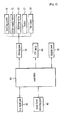
- FIG. 2 is a block diagram showing a constitution of a dish washer with a UV sterilization device in accordance with the present invention.
- a dish washer of the present invention comprises a key input part 30 for selecting a washing course and whether to operate a sterilization function or not; a water level detecting part 40 for detecting the water level in a tub; a driving part 50 for operating a washing motor 51, a water supply valve 53, a draining valve 55, a heater 57 and a fan motor 59; a UV lamp (or a UV LED) 60 for emitting ultraviolet rays for sterilizing the dishes which are completely washed and dried; a display part 70 for displaying a washing procedure; a controller 80 for controlling a load necessary for the washing procedure and controlling the UV lamp 60 for sterilizing the dishes and the driving part 50 to operate the fan motor 59 for ventilating the tub when washing, rinsing and drying processes are finished.
- the UV lamp 60 emits the ultraviolet rays to sterilize the dishes for a predetermined time.
- the fan motor 59 is driven to transmit its driving force to a fan for exhausting air in the tub outside.
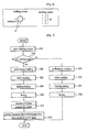
- the key input part 30 may include control panels which are shown FIGs. 5 and 6 .
- the control panel depicted in FIG. 5 is provided with a washing course selecting knob 31 for selecting the washing course and a sterilization selecting button 32 for allowing a user to select whether to perform the UV sterilization or not.
- the commands selected by manipulating the washing course selecting knob 31 and the sterilization selecting button 32 are displayed through LEDs (Light Emitting Diodes) 33 and 34, to thereby inform the user of the selected commands.
- LEDs Light Emitting Diodes
- the control panel depicted in FIG. 6 is provided with a washing course selecting knob 35 for selecting the washing course.
- One of the programmed washing courses includes a UV sterilizing process. In other words, if the user selects a "washing course 4" ( see FIG. 6 ), the UV sterilizing process is performed while the "washing course 4" is performed.
- the command selected by manipulating the washing course selecting knob 35 is displayed through LEDs 36.
- the user loads the contaminated dishes on racks in the tub. And, the user selects the washing course and whether to perform the sterilization or not in consideration of the amount and kinds of the dishes to be washed by manipulating the key input part 30 at step S10.
- the controller 80 determines if the washing course including the sterilizing process is selected by the user at step S20. If the controller 80 determines that the washing course selected by the user does not include the sterilizing process, the controller 80 performs the washing procedure according to algorithm corresponding to the selected washing course without performing the sterilizing process.
- the water supply valve 53 is opened to supply the water, and the water level detecting part 40 detects the water level.
- the water supply valve 53 is closed to stop the water-supply.
- the draining valve 55 is opened to discharge the water used in the preliminary washing process, and the water supply valve 53 is opened to supply again the water to the predetermined water level.
- the heater 57 By driving the heater 57 to heat the water and spraying the heated water at the dishes, a main washing process is performed at step S32.
- the draining valve 55 is opened to discharge the water used in the main washing process, and the water supply valve 53 is opened to again supply the water.
- a heating-rinsing process is performed to remove the remaining garbage or the detergent from the dishes at step S34.
- the water it is preferable to heat the water to a temperature (e.g., about 80°C) enough for the sterilization. Therefore, the rinsing and the sterilization using the hot water are performed at the same time.
- the preliminary washing process, the main washing process, the heating-rinsing process and the drying process are performed in order.
- a preliminary washing process is performed at step S40.
- a main washing process is performed at step S42.
- a heating-rinsing process is performed at step S44.
- the heating-rinsing process is completed, by driving the fan motor 59 to rotate the fan for exhausting the air in the tub outside and removing the water from the dishes, a drying process is performed at step S46.
- the UV lamp 60 and the fan motor 59 are driven for predetermined time (e.g., for 25 minutes or more) at step S48.
- the UV lamp 60 is driven to sterilize the dishes
- the fan motor 59 is driven to rotate the fan for exhausting the air and the harmful gas like ozone in the tub, which may be generated during the sterilizing process, and removing the bad smell.
- the operation of the UV lamp 60 is stopped, but the fan motor 59 is continuously driven to sufficiently ventilate the tub for predetermined time (e.g., for about 35 minutes) at step S50.
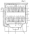
- FIG. 3 is a side cross-sectional view schematically showing the dish washer in accordance with a preferred embodiment of the present invention. Same reference numerals are given to the same components of the dish washer of the present invention as the components of the dish washer of the prior art depicted in FIG. 1 , and detailed explanation thereof will be omitted.
- the dish washer comprises a UV lamp 10 provided near a filtering device 9 in a tub 2, a fan 11 mounted to a door 1 a for exhausting the air in the tub 2 outside, and a controller (not shown) for controlling the UV sterilizing process.
- the UV lamp 10 is located in the tub 2 near the filtering device 9, however, the position of the UV lamp 10 may be diversely changed.
- the filtering device 9 filters the contaminants like the garbage out of the water which is sprayed from washing arms 4 and used for washing the dishes.
- the ultraviolet rays emitted from the UV lamp 10 can reach the filtering device 9 as well as the inside of the tub 2, thereby sterilizing them together.
- the door 1a is formed with an air passage 12, and the fan 11 is located in the air passage 12.
- the fan 11 rotates by a driving force of a fan motor. As the fan 11 rotates, the air in the tub 2 is exhausted outside.
- the controller controls the operation of the UV lamp 10 to sterilize the dishes, and controls the operation of the fan 11 to exhaust the bad smell and the harmful gas in the tub 2 outside. Because the controller can control the operation of the UV lamp 10 for the UV sterilization according to the control method described above with reference to FIG. 7 , the explanation of the control method will be omitted.
- FIG. 4 is a cross-sectional view showing a dish washer in accordance with another preferred embodiment of the present invention.
- FIG. 4 illustrates only a driving part which is mounted under the tub.
- the overall structure except the driving part of this embodiment may be identical to the structure of the previous embodiment.
- the dish washer of this embodiment may not include the UV lamp 10 of the previous embodiment ( see FIG. 3 ).
- the dish washer comprises a sump 110 for accommodating the water, a washing pump 120 for pumping the water in the sump 110, housing assembly 130, 140 and 150 having water passages for guiding the pumped water to washing arms, a cover 160 for covering an upper portion of the sump 110, a filtering device 170 mounted in the sump 110 while passing through the cover 160 for filtering the water dropped on the cover 160 and guiding the filtered water into the sump 110, a draining pump 180 communicated with the filtering device 170 for discharging the water in the sump 110 outside, a UV lamp 100 mounted near the lower end of the filtering device 170 for sterilizing the filtering device 170, and a heater (not shown) mounted in the sump 110 for heating the water.
- the sump 110 is formed with a contaminant accommodating chamber 111. It is preferable that the contaminant accommodating chamber 111 is disposed at the bottom of sump 110. It is further preferable that the contaminant accommodating chamber 111 is slanted toward the draining pump 180 by an angle of, so as to easily exhaust the contaminants collected in the contaminant accommodating chamber 111 to the draining pump 180.
- a discharging passage 112 is formed between the contaminant accommodating chamber 111 and the draining pump 180 to communicate them with each other.
- the sump 110 is formed with a draining chamber 113 for mounting the draining pump 180. It is preferable that the contaminant accommodating chamber 111 communicates with the draining chamber 113 through the discharging passage 112.
- the draining chamber 113 is provided with an impeller (not shown).
- the washing pump 120 includes a washing motor 121 for generating a driving force, and an impeller 122 which is shaft-coupled to the washing motor 121.
- the washing motor 121 is disposed such that its driving shaft extends vertically.
- the draining pump 180 includes a draining motor (not shown) and an impeller (not shown). The draining motor is disposed such that its driving shaft extends horizontally.
- the housing assembly 130, 140 and 150 includes a pump chamber 131 in which the impeller 122 of the washing pump 120 is located, a flow control chamber 132 which communicates with the pump chamber 131 and in which a flow control valve 190 is mounted, and main water passages 141 and 142 for guiding the water in the flow control chamber 132 to the washing arms.
- the pump chamber 131 and the flow control chamber 132 are disposed on the same plane. This is for decreasing a height of the housing assembly 130, 140 and 150 and increasing the inner space of the sump 110. It is preferable to dispose the main water passages 141 and 142 on the pump chamber 131 and the flow control chamber 132. This is for decreasing an area of the housing assembly 130, 140 and 150.
- the housing assembly includes a lower housing 130 which has the pump chamber 131 and the flow control chamber 132, and an upper housing 140 which covers an upper portion of the lower housing 130 and has the main water passages 141 and 142.
- the lower housing 130 and the upper housing 140 may be formed as separate members as shown in FIG. 4 , or may be formed integrally with each other.
- the housing assembly may further include a connecting housing 150 which covers an upper portion of the upper housing 140.
- a connecting pipe (not shown) connected to the washing arms is coupled to the connecting housing 150.
- the connecting housing 150 is formed with a coupling part (not shown) to which the connecting pipe is coupled.
- the cover 160 which covers the sump 110 is slanted toward the filtering device 170 by an angle of ⁇ . This is in order that the water and the contaminants dropped on the cover 160 can easily flow to the filtering device 170.
- the filtering device 170 has an opened lower end.
- the opened lower end of the filtering device 170 is coupled to the contaminant accommodating chamber 111. It is preferable that the lower end of the filtering device 170 is spaced apart from a bottom of the contaminant accommodating chamber 111.
- a stepped portion is formed at an upper end of the contaminant accommodating chamber 111, so that the opened lower end of the filtering device 170 is supported by the stepped portion.
- the discharging passage 112 is disposed under the stepped portion of the contaminant accommodating chamber 111. Therefore, the contaminants in the contaminant accommodating chamber 111 are exhausted to the draining chamber through the discharging passage 112 without interference with the filtering device 170.
- the filtering device 170 includes an upper filter 176 and a lower filter 171.
- the upper filter 176 and the lower filter 171 are detachably coupled to the cover 160.
- the upper filter 176 filters relatively large garbage
- the lower filter 171 filters relatively small garbage which is not filtered by the upper filter 176.
- the lower filter 171 is coated with a photocatalyst material.
- the upper filter 176 may protrude from the upper surface of the cover 160 by a predetermined height, so that the user can easily grasp the upper filter 176 and draw out the same. On the other hand, if the upper filter 176 has a structure that the user can easily draw out, the upper filter 176 does not necessarily protrude from the upper surface of the cover 160.
- the UV lamp 100 is disposed near the lower end of the lower filter 171.
- the sterilizing effect varies according the position to which the UV lamp 100 emits the ultraviolet rays. It is most effective when the UV lamp 100 is located near the lower end of the lower filter 171 and emits the ultraviolet rays to the filtering device 170. Accordingly, it is preferable to dispose the UV lamp 100 at a side of the contaminant accommodating chamber 111. And, the UV lamp 100 is slantingly mounted to prevent the contaminants from building up thereon.
- the flow control valve 190 includes a rotating shaft 191 which is coupled to a driving shaft of a control motor 200, and an opening/closing plate 192 which is mounted at a top of the rotating shaft 191 and is formed with a communicating hole 192a. As the opening/closing plate 192 rotates, the plate 192 opens or closes the main water passages 141 and 142. Because the main water passages 141 and 142 are located on the flow control valve 190, the flow control valve 190 can be formed in a plate shape.
- the pumping pressure of the washing pump 120 acts on the upper portion of the flow control valve 190, so that the pumping pressure biases the flow control valve 190 to the upper housing 140, so that the flow control valve 190 can be stably supported without rattling.
- the inner surfaces of the sump 110 and the main water passages 141 and 142 are coated with a nano-silver material. This is because the nano-silver material having an antifungal effect prevents the bacteria from propagating due to the water remaining in the sump 110 and the main water passages 141 and 142.
- the dish washer operates by a water supplying process, a washing process, a draining process, a heating-rinsing process, a drying/sterilizing process, and a deodorizing process.
- the water supplying process is performed at step S 110 in such a manner that the water is supplied into the sump 110 with the detergent.
- the water is supplied to the predetermined level.
- the washing process is performed at step S120.
- the washing motor 121 is driven, the impeller 122 rotates and the water in the sump 110 flows to the pump chamber 131 and the flow control chamber 132.
- the flow control valve 190 rotates to communicate the main water passages 141 and 142 with the flow control chamber 132.
- the flow control valve 190 may selectively open one of the main water passages 141 and 142, or may simultaneously open both the main water passages 141 and 142. Also, the flow control valve 190 may alternately open and close the main water passages 141 and 142.
- the washing pump 120 having relatively smaller capacity can be used, and the consumption of the water is considerably decreased.
- the water drops on the cover 160. Because the cover 160 is slanted toward the filtering device 170, the water and the contaminants dropped on the cover 160 flow to the upper filter 176. A part of the water directly flows into the sump 110 through the filtering holes 161 of the cover 160.
- the upper filter 176 filters the relatively large garbage
- the lower filter 171 filters the relatively small garbage which is not filtered by the upper filter 176. As a result, only the water from which the contaminants are filtered flows into the sump 110.
- the dishes are washed while the contaminants are filtered from the water.
- the amount of the contaminants like the garbage collected in the filtering device 170 is gradually increased.
- the draining process is performed at step S130.
- the draining pump 180 When the draining pump 180 is driven, the water in the sump 110 flows into the contaminant accommodating chamber 111 through the lower filter 171 by a sucking force of the draining pump 180. Then, the water flows into the draining chamber 113 with the contaminants collected in the contaminant accommodating chamber 111. Because the contaminant accommodating chamber 111 is slanted toward the draining chamber 113, the contaminants can smoothly flow into the draining chamber 113. The water and the contaminants in the draining chamber 113 are discharged outside through a draining hole and a draining hose of the draining chamber 113.
- the rinsing (preferably, the heating-rinsing) process is performed at step S140. It is preferable that the rinsing and the sterilization using the hot water are performed simultaneously.
- the water is heated by the heater mounted in the sump 110 to the predetermined temperature, and the heated water is sprayed to the dishes from the washing arms, thereby increasing the rinsing ability and sterilizing the dishes at the same time.
- the water is heated to the temperature of about 80°C.
- the water is discharged. Then, the drying/sterilizing process is performed at step S150.
- the sterilization means a UV sterilization.
- the UV lamp 100 emits the ultraviolet rays to the filtering device 170, to sterilize the filtering device 170 and the contaminant accommodating chamber 111. Since the surface of the lower filter 176 is coated with the photocatalyst material, the photocatalyst material receives the ultraviolet rays emitted from the UV lamp 100 and generates the chemical reaction, to reinforce the sterilizing effect. Accordingly, the lower filter 176 in which the minute contaminants may remain can be sterilized more intensively.
- the deodorizing process is performed at step S160.
- the fan mounted to the door rotates to exhaust the harmful gas like ozone which may be generated during the operation of the UV lamp.
- the deodorizing process means a ventilating process.
- the dish washer according to the present invention has structural features of including the UV sterilizing device capable of sterilizing the inside of the dish washer and the fan capable of exhausting the harmful gas which may be generated during the sterilizing process.
- the fan also exhausts the air in the tub outside, so the bad smell in the dish washer is removed.
- the dishes can be washed so they are clean and sanitary clean, and the inside of the dish washer can be maintained in a hygienic state.
- the sterilizing effect is increased by making up for the weak points of both sterilizing methods.
- the present invention can be similarly applied to the different types of the dish washers which do or do not have the filtering device.
Landscapes
- Apparatus For Disinfection Or Sterilisation (AREA)
Description
- The present invention relates to a dish washer, and more particularly to a dish washer and a control method thereof, which includes a UV sterilization device for sterilizing inside of the dish washer and a fan for exhausting harmful gas which may be generated during the sterilization.
- Generally, a dish washer is an apparatus for washing dishes contaminated with garbage by spraying water containing detergent, and drying the same.
- The dish washer helps a user to conveniently wash the dishes, and is very useful, particularly, for the elderly and the disabled. The dish washer also provides the user with spare time enough to do other works during the operation. So, the demand for the dish washer has been increased recently.
- The dish washer is classified into two types. One has a filtering device for collecting the garbage removed from the dishes during the washing. And, the other does not have the filtering device. In the former, the user must eliminate the garbage collected in the filtering device by hand. In the latter, the dish washer has a function of pulverizing the garbage and discharging the same with the water.
-
FIG. 1 is a side cross-sectional view schematically showing a dish washer of a prior art. As shown in the drawing, a dish washer comprises amain body 1, atub 2, a drivingpart 3, washingarms 4, awashing pump 5, and a drainingpump 6. - The
main body 1 protects the components of the dish washer and forms an exterior appearance. Themain body 1 is equipped with a door la at a portion for putting or taking the dishes into or from thetub 2. - The
tub 2 is formed inside themain body 1, which provides a space where the dishes are washed.Racks 7 on which the dishes are loaded are provided in thetub 2. Generally, theracks 7 are located at an upper portion and a lower portion in thetub 2. - The driving
part 3 for operating the dish washer is mounted under thetub 2. The drivingpart 3 includes a sump (not shown) for accommodating the water, a heater (not shown) mounted to the sump for heating the water, and a filtering device (not shown) for filtering the garbage removed from the dishes. - The
washing arms 4 have a function of spraying the water accommodated in the sump at the dishes loaded on theracks 7. Thewashing arms 4 are connected towater passages 8 extending from the sump, and respectively mounted under thecorresponding racks 7. - The
washing pump 5 is mounted under thedriving part 3. Thewashing pump 5 supplies the water accommodated in the sump to thewashing arms 4 through thewater passages 8. - The draining
pump 6 is connected to the filtering device of thedriving part 3. The drainingpump 6 discharges the water outside, which is used for washing the dishes. - However, since the dish washer of the prior art is not equipped with a device for sterilizing the washed dishes, there is a sanitary problem.
- Because the garbage may remain in the dish washer, the dish washer is in danger of being contaminated with bacteria. Especially, the filtering device provides a good environment for the propagation of bacteria.
- Further, because the bacteria tend to propagate well in humid environment, the bacteria are not exterminated just by a wet type sterilization device which uses hot water. The bacteria re-propagate due to the humidity of the wet type sterilization device itself.
- Accordingly, the dish washer capable of sterilizing the inside of the dish washer, especially, equipped with a dry type sterilization device is required.
- Examples of prior art dishwashers comprising UV sterilization devices are described in
GB 2192126 WO 2004/058038 andEP 1550396 . -
GB 2192126 - In order to sterilize the eating utensils, an UV device is disposed within the washing chamber. During the blowing of air on the dishes, the UV device operates to sterilize the dishes.
-
WO 2004/058038 describes a dishwasher that comprises a washing tub where appliances are put, a sump under the washing tub where the water in the washing tub is collected during the washing process and a heater which is used to heat the washing water. A circulation pump is also provided for returning collected water to the washing tub and an evacuation pump which discharges the collected water in the sump. - UV lamps are placed in the washing tub to eliminate germs during a drying cycle following a washing cycle.
-
EP 1550396 describes a dishwasher that includes a cabinet having a washing room formed in the cabinet for receiving dishes and an injection arm for injecting washing water toward the dishes. The machine further includes a heater for heating the washing water, an air ventilation hole for discharging humid air while the dishes are dried and an UV lamp to activate titanium oxide, which provides a physical deodorizing effect. - Accordingly, the present invention is directed to a dish washer with a UV sterilization device and a control method thereof that substantially obviate one or more problems due to limitations and disadvantages of the related art.
- An object of the present invention devised to solve the problem lies on a dish washer which includes a UV sterilization device capable of sterilizing the inside of the dish washer, especially, a tub or a filtering device.
- Another object of the present invention devised to solve the problem lies on a dish washer which includes a fan capable of exhausting the air in the tub outside, thereby removing bad smell from the dish washer and exhausting harmful gas like ozone which may be generated during the sterilization.
- The object of the present invention can be achieved by providing a dish washer comprising: a UV emitting device for emitting ultraviolet rays for sterilizing at least a portion of inside of the dish washer; a fan for exhausting air in a tub outside; and a controller for controlling operations of the UV emitting device and the fan so that the fan operates for at least a part of time while the UV emitting device operates and for predetermined time from when the operation of the UV emitting device is completed for completely exhausting the air in the tub. According to the invention, the fan is capable of exhausting air in the tub outside, thereby removing bad smell from the dish washer and exhausting harmful gas like ozone which may be generated during the sterilization.
- Preferably, the UV emitting device is a UV lamp or a UV LED. The ultraviolet rays emitted from the UV emitting device exterminate the bacteria. Hereinafter, the UV lamp is a general term including the UV LED.
- Preferably, the UV emitting device emits ultraviolet rays to inside of the tub in which dishes are received. The UV emitting device may be mounted to an inner wall of the tub.
- Preferably, the dish washer further comprises: a filtering device for filtering water. The UV emitting device emits the ultraviolet rays to the filtering device. Because the filtering device provides a good environment for the propagation of the bacteria by contaminants like garbage collected therein, the filtering device is necessarily sterilized.
- Preferably, the UV emitting device is mounted under the filtering device. This is for preventing the contaminants from building up on the UV emitting device and obstructing the emission of the ultraviolet rays. The contaminants are captured in the filtering device and do not build up on the UV emitting device.
- Preferably, the UV emitting device is slantingly mounted, so that the contaminants which may be dropped on the UV emitting device are easily removed from the UV emitting device by being slid down in itself or by the water.
- Preferably, the UV emitting device emits the ultraviolet rays to inside of the tub as well as the filtering device. For this, the mounting position of the UV emitting device may be determined properly, or the intensity of the ultraviolet rays may be increased. For example, the UV emitting device may be mounted to the inner wall of the tub or near the filtering device.
- When a user takes the dishes from the dish washer before the predetermined sterilization time lapses, it is preferable that the controller controls the UV emitting device to stop and complete the operation. For this, the dish washer further comprises: a detecting device for detecting opening and closing of a door of the dish washer. The controller controls the UV emitting device to operate for predetermined time. When the door is opened and closed before the predetermined time lapses, the controller determines that the dishes have been put out of the tub by a user and controls the UV emitting device to stop and complete the operation. Preferably, a door locking structure or a limit switch may be used as the detecting device.
- Preferably, the dish washer further comprises: a heater for heating water for sterilization; and a spraying device for spraying the water heated by the heater. It is preferable to heat the water to a temperature of 80°C.
- When the both sterilizations by using hot water and by the UV emitting device are performed, the sterilizing effect is increased by making up for the weak points of both sterilizing methods. In other words, the sterilization using hot water is more effective in sterilizing a driving part having a sump and a washing pump. And, a wave band of the ultraviolet rays emitted from the UV emitting device may be adjusted to effectively exterminate the bacteria which survive the hot water sterilization.
- Preferably, the dish washer further comprises: a course selecting button for a user selecting a washing course; and a sterilization selecting button for the user selecting to perform the sterilization using the UV emitting device. Because the sterilization selecting button is provided separately from the course selecting button, only the sterilization can be performed without performing a washing process, thereby providing the user with convenience in use.
- Preferably, the dish washer further comprises: a course selecting button for selecting one of multiple washing courses. At least one of the multiple washing courses includes a sterilizing process using a UV emitting device. Therefore, the user can select the washing course having the sterilizing process. The selecting button may be diversely combined, to thereby increase the convenience in use.
- In another aspect of the present invention, there is provided a method of controlling a dish washer comprising the steps of: (a) washing dishes received in a tub by using water; (b) rinsing the dishes which are washed; (c) sterilizing the dishes by using water which is heated; (d) drying the dishes; (e) sterilizing at least a portion of inside of the dish washer by using ultraviolet rays; and (f) exhausting air in the tub outside for at least a part of time while the step (e) is performed and for predetermined time from when the step (e) is completed.
- Preferably, the water is heated to a temperature of 80°C in the step (C). The step (c) may be performed together with the step (b) at the same time.
- Preferably, when predetermined time lapses from when the step (f) is completed, the step (e) and the step (f) are additionally performed. This is because the user occasionally leaves the dishes in the dish washer even after the completion of the washing procedure from the step (a) to the step (f).
- A dish washer with a UV sterilization device according to the present invention can wash the dishes so they are clean and sanitary, and maintain the inside of the dish washer in a hygienic state by sterilizing the inside (especially, a tub or a filtering device) of the dish washer.
- The dish washer according to the present invention includes a fan capable of exhausting air in the tub outside, thereby removing bad smell from the dish washer and exhausting harmful gas like ozone which may be generated during the sterilization.
- Also, when the sterilization using hot water and the UV sterilization are performed at the same time, the sterilizing effect is increased by making up for the weak points of both sterilizing methods.
- The accompanying drawings, which are included to provide a further understanding of the invention, illustrate embodiments of the invention and together with the description serve to explain the principle of the invention.
- In the drawings:
-
FIG. 1 is a side cross-sectional view schematically showing a dish washer of a prior art; -
FIG. 2 is a block diagram showing a constitution of a dish washer with a UV sterilization device in accordance with the present invention; -
FIG. 3 is a side cross-sectional view schematically showing a dish washer with a UV sterilization device in accordance with a preferred embodiment of the present invention; -
FIG. 4 is a cross-sectional view showing a dish washer with a UV sterilization device in accordance with another preferred embodiment of the present invention; -
FIG. 5 is a schematic view showing an example of a control panel of a key input part; -
FIG. 6 is a schematic view showing another example of a control panel of a key input part; -
FIG. 7 is a flow chart showing a method of controlling a dish washer in accordance with the present invention; and -
FIG. 8 is a flow chart showing an operation of a dish washer in accordance with the present invention. - Reference will now be made in detail to the preferred embodiments of the present invention, examples of which are illustrated in the accompanying drawings.
-
FIG. 2 is a block diagram showing a constitution of a dish washer with a UV sterilization device in accordance with the present invention. - As shown in the drawing, a dish washer of the present invention comprises a
key input part 30 for selecting a washing course and whether to operate a sterilization function or not; a waterlevel detecting part 40 for detecting the water level in a tub; a drivingpart 50 for operating awashing motor 51, awater supply valve 53, a drainingvalve 55, aheater 57 and a fan motor 59; a UV lamp (or a UV LED) 60 for emitting ultraviolet rays for sterilizing the dishes which are completely washed and dried; adisplay part 70 for displaying a washing procedure; acontroller 80 for controlling a load necessary for the washing procedure and controlling theUV lamp 60 for sterilizing the dishes and the drivingpart 50 to operate the fan motor 59 for ventilating the tub when washing, rinsing and drying processes are finished. - When the drying process is finished, the
UV lamp 60 emits the ultraviolet rays to sterilize the dishes for a predetermined time. In addition, during the operation of theUV lamp 60, the fan motor 59 is driven to transmit its driving force to a fan for exhausting air in the tub outside. - The
key input part 30 may include control panels which are shownFIGs. 5 and6 . The control panel depicted inFIG. 5 is provided with a washingcourse selecting knob 31 for selecting the washing course and asterilization selecting button 32 for allowing a user to select whether to perform the UV sterilization or not. The commands selected by manipulating the washingcourse selecting knob 31 and thesterilization selecting button 32 are displayed through LEDs (Light Emitting Diodes) 33 and 34, to thereby inform the user of the selected commands. - The control panel depicted in
FIG. 6 is provided with a washingcourse selecting knob 35 for selecting the washing course. One of the programmed washing courses includes a UV sterilizing process. In other words, if the user selects a "washing course 4" (seeFIG. 6 ), the UV sterilizing process is performed while the "washing course 4" is performed. The command selected by manipulating the washingcourse selecting knob 35 is displayed throughLEDs 36. - Hereinafter, a method of controlling the dish washer according to the present invention will be described with reference to
FIG. 7 . - The user loads the contaminated dishes on racks in the tub. And, the user selects the washing course and whether to perform the sterilization or not in consideration of the amount and kinds of the dishes to be washed by manipulating the
key input part 30 at step S10. - The
controller 80 determines if the washing course including the sterilizing process is selected by the user at step S20. If thecontroller 80 determines that the washing course selected by the user does not include the sterilizing process, thecontroller 80 performs the washing procedure according to algorithm corresponding to the selected washing course without performing the sterilizing process. - First, the
water supply valve 53 is opened to supply the water, and the waterlevel detecting part 40 detects the water level. When the water level detected by the detectingpart 40 reaches a predetermined value, thewater supply valve 53 is closed to stop the water-supply. By repeatedly performing and stopping the spraying of the water containing the detergent at the dishes loaded on the racks in the tub at predetermined times, a preliminary washing process is performed at step S30. - When the preliminary washing process is completed, the draining
valve 55 is opened to discharge the water used in the preliminary washing process, and thewater supply valve 53 is opened to supply again the water to the predetermined water level. By driving theheater 57 to heat the water and spraying the heated water at the dishes, a main washing process is performed at step S32. - When the main washing process is completed, the draining
valve 55 is opened to discharge the water used in the main washing process, and thewater supply valve 53 is opened to again supply the water. By heating the water and using the heated water, a heating-rinsing process is performed to remove the remaining garbage or the detergent from the dishes at step S34. - At this time, it is preferable to heat the water to a temperature (e.g., about 80°C) enough for the sterilization. Therefore, the rinsing and the sterilization using the hot water are performed at the same time.
- When the preliminary washing process, the main washing process and the heating-rinsing process are completed, by driving the fan motor 59 to rotate the fan for exhausting the air in the tub outside and removing the water from the dishes, a drying process is performed at step S36.
- Conclusively, in case of the washing course which does not include the sterilizing process, the preliminary washing process, the main washing process, the heating-rinsing process and the drying process are performed in order.
- On the other hand, if the user selects the washing course including the sterilizing process, by repeatedly performing and stopping the spraying of the water containing the detergent at the dishes, a preliminary washing process is performed at step S40. When the preliminary washing process is completed, by driving the
heater 57 to heat the water and spraying the heated water at the dishes, a main washing process is performed at step S42. When the main washing process is completed, by heating the water and using the heated water, a heating-rinsing process is performed at step S44. When the heating-rinsing process is completed, by driving the fan motor 59 to rotate the fan for exhausting the air in the tub outside and removing the water from the dishes, a drying process is performed at step S46. - When the drying process is completed, in order to sterilize the dried dishes and remove the garbage smell from the dishes, the
UV lamp 60 and the fan motor 59 are driven for predetermined time (e.g., for 25 minutes or more) at step S48. In other words, theUV lamp 60 is driven to sterilize the dishes, and the fan motor 59 is driven to rotate the fan for exhausting the air and the harmful gas like ozone in the tub, which may be generated during the sterilizing process, and removing the bad smell. - When the predetermined time for driving the
UV lamp 60 passes, the operation of theUV lamp 60 is stopped, but the fan motor 59 is continuously driven to sufficiently ventilate the tub for predetermined time (e.g., for about 35 minutes) at step S50. -
FIG. 3 is a side cross-sectional view schematically showing the dish washer in accordance with a preferred embodiment of the present invention. Same reference numerals are given to the same components of the dish washer of the present invention as the components of the dish washer of the prior art depicted inFIG. 1 , and detailed explanation thereof will be omitted. - As shown in
FIG. 3 , the dish washer comprises aUV lamp 10 provided near a filtering device 9 in atub 2, afan 11 mounted to a door 1 a for exhausting the air in thetub 2 outside, and a controller (not shown) for controlling the UV sterilizing process. - It is illustrated in
FIG. 3 that theUV lamp 10 is located in thetub 2 near the filtering device 9, however, the position of theUV lamp 10 may be diversely changed. The filtering device 9 filters the contaminants like the garbage out of the water which is sprayed from washingarms 4 and used for washing the dishes. The ultraviolet rays emitted from theUV lamp 10 can reach the filtering device 9 as well as the inside of thetub 2, thereby sterilizing them together. - The door 1a is formed with an
air passage 12, and thefan 11 is located in theair passage 12. Thefan 11 rotates by a driving force of a fan motor. As thefan 11 rotates, the air in thetub 2 is exhausted outside. - The controller controls the operation of the
UV lamp 10 to sterilize the dishes, and controls the operation of thefan 11 to exhaust the bad smell and the harmful gas in thetub 2 outside. Because the controller can control the operation of theUV lamp 10 for the UV sterilization according to the control method described above with reference toFIG. 7 , the explanation of the control method will be omitted. -
FIG. 4 is a cross-sectional view showing a dish washer in accordance with another preferred embodiment of the present invention.FIG. 4 illustrates only a driving part which is mounted under the tub. The overall structure except the driving part of this embodiment may be identical to the structure of the previous embodiment. On the other hand, the dish washer of this embodiment may not include theUV lamp 10 of the previous embodiment (seeFIG. 3 ). - As shown in
FIG. 4 , the dish washer comprises a sump 110 for accommodating the water, awashing pump 120 for pumping the water in the sump 110,housing assembly cover 160 for covering an upper portion of the sump 110, afiltering device 170 mounted in the sump 110 while passing through thecover 160 for filtering the water dropped on thecover 160 and guiding the filtered water into the sump 110, a drainingpump 180 communicated with thefiltering device 170 for discharging the water in the sump 110 outside, aUV lamp 100 mounted near the lower end of thefiltering device 170 for sterilizing thefiltering device 170, and a heater (not shown) mounted in the sump 110 for heating the water. - The sump 110 is formed with a
contaminant accommodating chamber 111. It is preferable that thecontaminant accommodating chamber 111 is disposed at the bottom of sump 110. It is further preferable that thecontaminant accommodating chamber 111 is slanted toward the drainingpump 180 by an angle of, so as to easily exhaust the contaminants collected in thecontaminant accommodating chamber 111 to the drainingpump 180. - A discharging
passage 112 is formed between thecontaminant accommodating chamber 111 and the drainingpump 180 to communicate them with each other. The sump 110 is formed with a drainingchamber 113 for mounting the drainingpump 180. It is preferable that thecontaminant accommodating chamber 111 communicates with the drainingchamber 113 through the dischargingpassage 112. The drainingchamber 113 is provided with an impeller (not shown). - The
washing pump 120 includes awashing motor 121 for generating a driving force, and animpeller 122 which is shaft-coupled to thewashing motor 121. Thewashing motor 121 is disposed such that its driving shaft extends vertically. The drainingpump 180 includes a draining motor (not shown) and an impeller (not shown). The draining motor is disposed such that its driving shaft extends horizontally. - The
housing assembly pump chamber 131 in which theimpeller 122 of thewashing pump 120 is located, aflow control chamber 132 which communicates with thepump chamber 131 and in which aflow control valve 190 is mounted, andmain water passages flow control chamber 132 to the washing arms. - It is preferable to dispose the
pump chamber 131 and theflow control chamber 132 on the same plane. This is for decreasing a height of thehousing assembly main water passages pump chamber 131 and theflow control chamber 132. This is for decreasing an area of thehousing assembly - Here, the housing assembly will now be described in detail. The housing assembly includes a
lower housing 130 which has thepump chamber 131 and theflow control chamber 132, and anupper housing 140 which covers an upper portion of thelower housing 130 and has themain water passages lower housing 130 and theupper housing 140 may be formed as separate members as shown inFIG. 4 , or may be formed integrally with each other. - The housing assembly may further include a connecting
housing 150 which covers an upper portion of theupper housing 140. A connecting pipe (not shown) connected to the washing arms is coupled to the connectinghousing 150. The connectinghousing 150 is formed with a coupling part (not shown) to which the connecting pipe is coupled. - It is preferable that the
cover 160 which covers the sump 110 is slanted toward thefiltering device 170 by an angle of β. This is in order that the water and the contaminants dropped on thecover 160 can easily flow to thefiltering device 170. - It is preferable to form a plurality of filtering holes 161 at the
cover 160 for allowing a part of the filtered water to directly flow into the tub. It is more preferable to dispose the filtering holes 161 at the positions with the exception of thehousing assembly housing assembly - The
filtering device 170 has an opened lower end. The opened lower end of thefiltering device 170 is coupled to thecontaminant accommodating chamber 111. It is preferable that the lower end of thefiltering device 170 is spaced apart from a bottom of thecontaminant accommodating chamber 111. - A stepped portion is formed at an upper end of the
contaminant accommodating chamber 111, so that the opened lower end of thefiltering device 170 is supported by the stepped portion. The dischargingpassage 112 is disposed under the stepped portion of thecontaminant accommodating chamber 111. Therefore, the contaminants in thecontaminant accommodating chamber 111 are exhausted to the draining chamber through the dischargingpassage 112 without interference with thefiltering device 170. - The
filtering device 170 includes anupper filter 176 and alower filter 171. Theupper filter 176 and thelower filter 171 are detachably coupled to thecover 160. Theupper filter 176 filters relatively large garbage, and thelower filter 171 filters relatively small garbage which is not filtered by theupper filter 176. Preferably, thelower filter 171 is coated with a photocatalyst material. - The
upper filter 176 may protrude from the upper surface of thecover 160 by a predetermined height, so that the user can easily grasp theupper filter 176 and draw out the same. On the other hand, if theupper filter 176 has a structure that the user can easily draw out, theupper filter 176 does not necessarily protrude from the upper surface of thecover 160. - The
UV lamp 100 is disposed near the lower end of thelower filter 171. The sterilizing effect varies according the position to which theUV lamp 100 emits the ultraviolet rays. It is most effective when theUV lamp 100 is located near the lower end of thelower filter 171 and emits the ultraviolet rays to thefiltering device 170. Accordingly, it is preferable to dispose theUV lamp 100 at a side of thecontaminant accommodating chamber 111. And, theUV lamp 100 is slantingly mounted to prevent the contaminants from building up thereon. - The
flow control valve 190 includes a rotating shaft 191 which is coupled to a driving shaft of acontrol motor 200, and an opening/closing plate 192 which is mounted at a top of the rotating shaft 191 and is formed with a communicatinghole 192a. As the opening/closing plate 192 rotates, the plate 192 opens or closes themain water passages main water passages flow control valve 190, theflow control valve 190 can be formed in a plate shape. Also, since the pumping pressure of thewashing pump 120 acts on the upper portion of theflow control valve 190, the pumping pressure biases theflow control valve 190 to theupper housing 140, so that theflow control valve 190 can be stably supported without rattling. - Preferably, the inner surfaces of the sump 110 and the
main water passages main water passages - Hereinafter, the operation of the dish washer structured as above will be described with reference to
FIG. 8 . The dish washer operates by a water supplying process, a washing process, a draining process, a heating-rinsing process, a drying/sterilizing process, and a deodorizing process. - The water supplying process is performed at step S 110 in such a manner that the water is supplied into the sump 110 with the detergent. The water is supplied to the predetermined level.
- Then, the washing process is performed at step S120. When the
washing motor 121 is driven, theimpeller 122 rotates and the water in the sump 110 flows to thepump chamber 131 and theflow control chamber 132. At this time, theflow control valve 190 rotates to communicate themain water passages flow control chamber 132. Theflow control valve 190 may selectively open one of themain water passages main water passages flow control valve 190 may alternately open and close themain water passages - When the
main water passages flow control chamber 132 flows to the washing arms through themain water passages washing pump 120 having relatively smaller capacity can be used, and the consumption of the water is considerably decreased. - After being sprayed from the washing arms and used for washing the dishes, the water drops on the
cover 160. Because thecover 160 is slanted toward thefiltering device 170, the water and the contaminants dropped on thecover 160 flow to theupper filter 176. A part of the water directly flows into the sump 110 through the filtering holes 161 of thecover 160. - The
upper filter 176 filters the relatively large garbage, and thelower filter 171 filters the relatively small garbage which is not filtered by theupper filter 176. As a result, only the water from which the contaminants are filtered flows into the sump 110. - When the washing process is performed for the predetermined time, the dishes are washed while the contaminants are filtered from the water. As the washing time passes, the amount of the contaminants like the garbage collected in the
filtering device 170 is gradually increased. - When the washing process is completed, the draining process is performed at step S130. When the draining
pump 180 is driven, the water in the sump 110 flows into thecontaminant accommodating chamber 111 through thelower filter 171 by a sucking force of the drainingpump 180. Then, the water flows into the drainingchamber 113 with the contaminants collected in thecontaminant accommodating chamber 111. Because thecontaminant accommodating chamber 111 is slanted toward the drainingchamber 113, the contaminants can smoothly flow into the drainingchamber 113. The water and the contaminants in the drainingchamber 113 are discharged outside through a draining hole and a draining hose of the drainingchamber 113. - When the draining process is completed, the rinsing (preferably, the heating-rinsing) process is performed at step S140. It is preferable that the rinsing and the sterilization using the hot water are performed simultaneously. The water is heated by the heater mounted in the sump 110 to the predetermined temperature, and the heated water is sprayed to the dishes from the washing arms, thereby increasing the rinsing ability and sterilizing the dishes at the same time. Preferably, the water is heated to the temperature of about 80°C.
- When the heating-rinsing process is completed, the water is discharged. Then, the drying/sterilizing process is performed at step S150. Here, the sterilization means a UV sterilization.
- The
UV lamp 100 emits the ultraviolet rays to thefiltering device 170, to sterilize thefiltering device 170 and thecontaminant accommodating chamber 111. Since the surface of thelower filter 176 is coated with the photocatalyst material, the photocatalyst material receives the ultraviolet rays emitted from theUV lamp 100 and generates the chemical reaction, to reinforce the sterilizing effect. Accordingly, thelower filter 176 in which the minute contaminants may remain can be sterilized more intensively. - While the sterilizing process is performed and after completion, the deodorizing process is performed at step S160. The fan mounted to the door rotates to exhaust the harmful gas like ozone which may be generated during the operation of the UV lamp. Here, the deodorizing process means a ventilating process.
- It will be apparent to those skilled in the art that various modifications and variations can be made in the present invention without departing from the scope of the invention. Thus, it is intended that the present invention covers the modifications and variations of this invention provided they come within the scope of the appended claims and their equivalents.
- The dish washer according to the present invention has structural features of including the UV sterilizing device capable of sterilizing the inside of the dish washer and the fan capable of exhausting the harmful gas which may be generated during the sterilizing process. The fan also exhausts the air in the tub outside, so the bad smell in the dish washer is removed.
- Because the inside (especially, the tub or the filtering device) of the dish washer can be sterilized, the dishes can be washed so they are clean and sanitary clean, and the inside of the dish washer can be maintained in a hygienic state.
- Further, when the sterilization using the hot water and the UV sterilization are performed at the same time, the sterilizing effect is increased by making up for the weak points of both sterilizing methods.
- Of course, the present invention can be similarly applied to the different types of the dish washers which do or do not have the filtering device.
Claims (12)
- A dish washer comprising:a UV emitting device (10, 100) for emitting ultraviolet rays for sterilizing at least a portion of inside of the dish washer;a fan (11) for exhausting air in a tub (2) outside; anda controller for controlling operations of the UV emitting device (10, 100) and the fan (11) so that the fan (11) operates for at least a part of time while the UV emitting device (10, 100) operates,
characterized in that
the controller controls the operation of the fan (11) so that the fan (11) further operates for predetermined time from when the operation of the UV emitting device (10, 100) is completed. - The dish washer according to claim 1, wherein the UV emitting device (10, 100) emits ultraviolet rays to inside of the tub (2) in which dishes are received.
- The dish washer according to claim 2, further comprising:a detecting device for detecting opening and closing of a door (1a) of the dish washer,wherein the controller controls the UV emitting device (10, 100) to operate for predetermined time, andwhen the controller determines that the door (1a) is opened and closed before the predetermined time lapses, the controller controls the UV emitting device (10, 100) to stop and complete the operation.
- The dish washer according to claim 1, further comprising:a heater (57) for heating water for sterilization; anda spraying device (4) for spraying the water heated by the heater.
- The dish washer according to claim 1, further comprising:a filtering device (9, 170) for filtering water,wherein the UV emitting device (10, 100) emits the ultraviolet rays to the filtering device (9, 170).
- The dish washer according to claim 5, wherein the UV emitting device (10) emits the ultraviolet rays also to inside of the tub (2).
- The dish washer according to claim 5, wherein the UV emitting device (100) is mounted under the filtering device (170).
- The dish washer according to claim 7, wherein the UV emitting device (100) is slantingly mounted.
- The dish washer according to claim 1, further comprising:a course selecting button for selecting a washing course (31); anda sterilization selecting button (32) for performing sterilization using the UV emitting device (10, 100).
- The dish washer according to claim 1, further comprising:a course selecting button (35) for selecting one of multiple washing courses,wherein at least one of the multiple washing courses includes a sterilizing process using the UV emitting device (10, 100).
- A method of controlling a dish washer according to any of claims 1-10 comprising the steps of:washing dishes received in a tub (2) by using water;rinsing the washed dishes;sterilizing the dishes by using heated water;drying the dishes;sterilizing at least a portion of inside of the dish washer by using ultraviolet rays; andexhausting air in the tub (2) outside for at least a part of time while the step of sterilizing by using ultraviolet rays is performed,characterized in that the step of exhausting air is further performed for predetermined time after the step of sterilizing by using ultraviolet rays is completed.
- The method according to claim 11, wherein after predetermined time lapses from when the step of exhausting air is completed, the step of sterilizing by using ultraviolet rays and the step of exhausting air are additionally performed.
Applications Claiming Priority (3)
| Application Number | Priority Date | Filing Date | Title |
|---|---|---|---|
| KR1020050076144A KR20070021648A (en) | 2005-08-19 | 2005-08-19 | Dishwasher with sterilization function and control method |
| KR1020050096508A KR20070040936A (en) | 2005-10-13 | 2005-10-13 | How to control your dishwasher |
| PCT/KR2006/003218 WO2007021137A1 (en) | 2005-08-19 | 2006-08-17 | Dish washer with uv sterilization device therein |
Publications (3)
| Publication Number | Publication Date |
|---|---|
| EP1915086A1 EP1915086A1 (en) | 2008-04-30 |
| EP1915086A4 EP1915086A4 (en) | 2012-02-08 |
| EP1915086B1 true EP1915086B1 (en) | 2016-10-12 |
Family
ID=37757768
Family Applications (1)
| Application Number | Title | Priority Date | Filing Date |
|---|---|---|---|
| EP06783628.8A Not-in-force EP1915086B1 (en) | 2005-08-19 | 2006-08-17 | Dish washer with uv sterilization device therein |
Country Status (4)
| Country | Link |
|---|---|
| US (1) | US20090110594A1 (en) |
| EP (1) | EP1915086B1 (en) |
| AU (1) | AU2006280595B2 (en) |
| WO (1) | WO2007021137A1 (en) |
Cited By (1)
| Publication number | Priority date | Publication date | Assignee | Title |
|---|---|---|---|---|
| DE102021204070A1 (en) | 2021-04-23 | 2022-10-27 | Osram Gmbh | OPTICAL ARRANGEMENT FOR DISINFECTION IN EQUIPMENT USED WITH AIR OR LIQUID |
Families Citing this family (28)
| Publication number | Priority date | Publication date | Assignee | Title |
|---|---|---|---|---|
| DE102008025205A1 (en) | 2008-05-27 | 2009-12-03 | BSH Bosch und Siemens Hausgeräte GmbH | Dish washing machine i.e. domestic washing machine, has washing container for accommodating washing goods, and odor removing device for removing odor, where odor removing device is arranged outside washing container |
| DE102008025204A1 (en) | 2008-05-27 | 2009-12-03 | BSH Bosch und Siemens Hausgeräte GmbH | Dish washing machine i.e. domestic washing machine, has washing container for accommodating washing goods, and odor removing device for removing odor, where odor removing device is arranged outside washing container |
| US10046073B2 (en) | 2010-06-01 | 2018-08-14 | Bluemorph, Llc | Portable UV devices, systems and methods of use and manufacturing |
| US11260138B2 (en) | 2010-06-01 | 2022-03-01 | Bluemorph, Llc | UV sterilization of container, room, space or defined environment |
| DE102010038689B4 (en) | 2010-07-30 | 2022-12-22 | BSH Hausgeräte GmbH | Water-bearing household appliance, in particular dishwasher |
| DE102010038686B4 (en) | 2010-07-30 | 2023-03-23 | BSH Hausgeräte GmbH | Water-bearing household appliance, in particular dishwasher |
| DE102010038692A1 (en) | 2010-07-30 | 2012-02-02 | BSH Bosch und Siemens Hausgeräte GmbH | Aquiferous household appliance i.e. dishwasher, has hydraulic circuit including water diverter, where UV radiation element is arranged such that UV irradiation of rinsing liquid takes place within water diverter |
| DE102010038690A1 (en) * | 2010-07-30 | 2012-02-02 | BSH Bosch und Siemens Hausgeräte GmbH | Aquiferous household appliance i.e. dishwasher, for cleaning dishes in dishwasher basket, has ultraviolet-radiation element sterilizing flushing liquid and/or fresh water temporarily stored in respective liquid containers |
| DE102010041215A1 (en) | 2010-09-22 | 2012-03-22 | BSH Bosch und Siemens Hausgeräte GmbH | Dishwasher, in particular household dishwasher |
| US20120144871A1 (en) * | 2010-12-14 | 2012-06-14 | Whirlpool Corporation | Laundry treating appliance with biofilm treating cycle |
| US8844082B2 (en) * | 2010-12-14 | 2014-09-30 | Whirlpool Corporation | Laundry treating appliance with biofilm treating cycle |
| CA2856196C (en) | 2011-12-06 | 2020-09-01 | Masco Corporation Of Indiana | Ozone distribution in a faucet |
| ITPR20130017U1 (en) * | 2013-10-03 | 2015-04-04 | Bake Off Italiana S R L | DOOR FOR COOKING OVEN FOR FOOD USE AND COOKING OVEN FOR FOOD |
| CN106618430A (en) * | 2015-11-04 | 2017-05-10 | 博西华电器(江苏)有限公司 | Dish washing machine and control method for dish washing machine |
| CN115093008B (en) | 2015-12-21 | 2024-05-14 | 德尔塔阀门公司 | Fluid delivery system including a sterilizing device |
| DE102016224729A1 (en) | 2016-12-12 | 2018-06-14 | BSH Hausgeräte GmbH | Dishwasher with a device for odor change |
| EP3381346B1 (en) * | 2017-03-31 | 2022-07-06 | V-Zug AG | Short washing program for a dish rack |
| JP7054767B2 (en) * | 2017-09-28 | 2022-04-15 | パナソニックIpマネジメント株式会社 | dishwasher |
| CN109744966B (en) * | 2017-11-07 | 2022-03-29 | 青岛海尔洗碗机有限公司 | Dishwasher and control method thereof |
| US10881751B2 (en) * | 2018-03-31 | 2021-01-05 | Sensor Electronic Technology, Inc. | Ultraviolet irradiation of food handling instruments |
| CN108903875B (en) * | 2018-08-17 | 2023-08-29 | 广东海伦宝家用电器有限公司 | Ultrasonic dish washer |
| CN111481689B (en) * | 2019-01-29 | 2021-05-18 | 宁波方太厨具有限公司 | Disinfection cabinet with air disinfection function |
| WO2021152339A1 (en) * | 2020-01-30 | 2021-08-05 | Genima Innovations Marketing Gmbh | Dishwasher with sterilizer |
| CN111851021B (en) * | 2020-06-24 | 2022-08-09 | 佛山市百斯特电器科技有限公司 | Ultraviolet lamp control method and device based on washing equipment |
| TR202018298A1 (en) * | 2020-11-16 | 2022-05-23 | Vestel Beyaz Esya San Ve Tic A S | A dishwasher with a sterilization function and how it works. |
| CN114749443A (en) * | 2022-05-07 | 2022-07-15 | 深圳市艾普生物科技有限公司 | Former storage bucket wiper mechanism that cleaning force is strong |
| CN115607073A (en) * | 2022-10-20 | 2023-01-17 | 海信(山东)厨卫有限公司 | Dishwasher and control method thereof |
| CN116269112B (en) * | 2022-12-08 | 2025-08-15 | 珠海格力电器股份有限公司 | Monitoring method and device for washing equipment and computer readable storage medium |
Family Cites Families (11)
| Publication number | Priority date | Publication date | Assignee | Title |
|---|---|---|---|---|
| US3571939A (en) * | 1969-09-04 | 1971-03-23 | Beverly Paul | Dish drying and sterilizing arrangement |
| DE2165864A1 (en) * | 1971-12-31 | 1973-07-05 | Laurent Alex Philippe | WASHING AND FLUSHING DEVICE FOR BAR TABLES |
| US3915180A (en) * | 1973-11-30 | 1975-10-28 | Gen Motors Corp | Dishwasher with energy radiating heat lamps |
| GB2192126A (en) * | 1986-07-02 | 1988-01-06 | Ho Mei Liu | Dishwasher |
| US5979472A (en) * | 1998-04-29 | 1999-11-09 | Lowery; Ginger E. | Toy washer and disinfector device |
| US6578586B2 (en) * | 2000-04-13 | 2003-06-17 | Chee Boon Moh | Single chamber dishwashing machine |
| EP1389939A4 (en) * | 2001-04-28 | 2005-01-26 | Jong-Hyun Myong | A washing device for a baby bottle |
| ES2286501T3 (en) * | 2002-12-25 | 2007-12-01 | Arcelik Anonim Sirketi | DISHWASHERS AND CORRESPONDING CONTROL PROCEDURE. |
| WO2005018407A2 (en) * | 2003-08-26 | 2005-03-03 | Alpert Martin A | Dishwasher and method |
| US20050150528A1 (en) * | 2003-12-26 | 2005-07-14 | Lg Electronics Inc. | Dish washing machine |
| EP1598470A1 (en) * | 2004-05-17 | 2005-11-23 | The Procter & Gamble Company | Method and system for washing |
-
2006
- 2006-08-17 WO PCT/KR2006/003218 patent/WO2007021137A1/en not_active Ceased
- 2006-08-17 US US11/997,243 patent/US20090110594A1/en not_active Abandoned
- 2006-08-17 EP EP06783628.8A patent/EP1915086B1/en not_active Not-in-force
- 2006-08-17 AU AU2006280595A patent/AU2006280595B2/en not_active Ceased
Non-Patent Citations (1)
| Title |
|---|
| None * |
Cited By (2)
| Publication number | Priority date | Publication date | Assignee | Title |
|---|---|---|---|---|
| DE102021204070A1 (en) | 2021-04-23 | 2022-10-27 | Osram Gmbh | OPTICAL ARRANGEMENT FOR DISINFECTION IN EQUIPMENT USED WITH AIR OR LIQUID |
| US12196450B2 (en) | 2021-04-23 | 2025-01-14 | Osram Gmbh | Optical arrangement for disinfection in apparatuses operating with air or a liquid |
Also Published As
| Publication number | Publication date |
|---|---|
| WO2007021137A1 (en) | 2007-02-22 |
| AU2006280595A1 (en) | 2007-02-22 |
| US20090110594A1 (en) | 2009-04-30 |
| EP1915086A4 (en) | 2012-02-08 |
| EP1915086A1 (en) | 2008-04-30 |
| AU2006280595B2 (en) | 2010-07-08 |
Similar Documents
| Publication | Publication Date | Title |
|---|---|---|
| AU2006280595B2 (en) | Dish washer with UV sterilization device therein | |
| CN101267760B (en) | Dishwasher with ultraviolet disinfection device and method for controlling dishwasher | |
| KR101283870B1 (en) | Sterilizing method for dish washer | |
| US7695572B2 (en) | Dishwasher and controlling method thereof | |
| EP2818091B1 (en) | Dishwasher | |
| US8181659B2 (en) | Washing machine having UV generator | |
| US5979472A (en) | Toy washer and disinfector device | |
| US7758705B2 (en) | Dishwasher having a door passage through which steam flows | |
| KR101151558B1 (en) | Dishwasher | |
| US9131826B2 (en) | Method for disinfecting conduit systems of a water-conducting appliance and such a household appliance | |
| KR101295273B1 (en) | dish cleaner | |
| US20090056763A1 (en) | Dish washing machine | |
| KR101259114B1 (en) | dish washer | |
| CN215383781U (en) | Dish washing machine | |
| JP5702197B2 (en) | Dishwasher | |
| JP2010187798A (en) | Dishwasher | |
| JP2000037341A (en) | Dish washer | |
| JP2010187797A (en) | Dishwasher | |
| JP2010187799A (en) | Dishwasher | |
| JPH02218328A (en) | Dishwasher | |
| KR20080022293A (en) | Dishwasher and Control Method | |
| KR20070040936A (en) | How to control your dishwasher | |
| JP2004187844A (en) | Dishwasher | |
| JP2012061160A (en) | Dishwasher |
Legal Events
| Date | Code | Title | Description |
|---|---|---|---|
| PUAI | Public reference made under article 153(3) epc to a published international application that has entered the european phase |
Free format text: ORIGINAL CODE: 0009012 |
|
| 17P | Request for examination filed |
Effective date: 20080311 |
|
| AK | Designated contracting states |
Kind code of ref document: A1 Designated state(s): AT BE BG CH CY CZ DE DK EE ES FI FR GB GR HU IE IS IT LI LT LU LV MC NL PL PT RO SE SI SK TR |
|
| A4 | Supplementary search report drawn up and despatched |
Effective date: 20120109 |
|
| RIC1 | Information provided on ipc code assigned before grant |
Ipc: A47L 15/42 20060101ALI20120103BHEP Ipc: A47L 15/00 20060101AFI20120103BHEP |
|
| DAX | Request for extension of the european patent (deleted) | ||
| GRAP | Despatch of communication of intention to grant a patent |
Free format text: ORIGINAL CODE: EPIDOSNIGR1 |
|
| RIC1 | Information provided on ipc code assigned before grant |
Ipc: A47L 15/00 20060101AFI20160512BHEP Ipc: A47L 15/42 20060101ALI20160512BHEP |
|
| INTG | Intention to grant announced |
Effective date: 20160609 |
|
| RIN1 | Information on inventor provided before grant (corrected) |
Inventor name: SHIN, DONG HOON Inventor name: KWON, SOON YONG |
|
| GRAS | Grant fee paid |
Free format text: ORIGINAL CODE: EPIDOSNIGR3 |
|
| GRAA | (expected) grant |
Free format text: ORIGINAL CODE: 0009210 |
|
| AK | Designated contracting states |
Kind code of ref document: B1 Designated state(s): AT BE BG CH CY CZ DE DK EE ES FI FR GB GR HU IE IS IT LI LT LU LV MC NL PL PT RO SE SI SK TR |
|
| REG | Reference to a national code |
Ref country code: GB Ref legal event code: FG4D |
|
| REG | Reference to a national code |
Ref country code: CH Ref legal event code: EP |
|
| REG | Reference to a national code |
Ref country code: AT Ref legal event code: REF Ref document number: 835688 Country of ref document: AT Kind code of ref document: T Effective date: 20161015 |
|
| REG | Reference to a national code |
Ref country code: IE Ref legal event code: FG4D |
|
| REG | Reference to a national code |
Ref country code: DE Ref legal event code: R096 Ref document number: 602006050575 Country of ref document: DE |
|
| REG | Reference to a national code |
Ref country code: LT Ref legal event code: MG4D |
|
| REG | Reference to a national code |
Ref country code: NL Ref legal event code: MP Effective date: 20161012 |
|
| PG25 | Lapsed in a contracting state [announced via postgrant information from national office to epo] |
Ref country code: LV Free format text: LAPSE BECAUSE OF FAILURE TO SUBMIT A TRANSLATION OF THE DESCRIPTION OR TO PAY THE FEE WITHIN THE PRESCRIBED TIME-LIMIT Effective date: 20161012 |
|
| REG | Reference to a national code |
Ref country code: AT Ref legal event code: MK05 Ref document number: 835688 Country of ref document: AT Kind code of ref document: T Effective date: 20161012 |
|
| PG25 | Lapsed in a contracting state [announced via postgrant information from national office to epo] |
Ref country code: SE Free format text: LAPSE BECAUSE OF FAILURE TO SUBMIT A TRANSLATION OF THE DESCRIPTION OR TO PAY THE FEE WITHIN THE PRESCRIBED TIME-LIMIT Effective date: 20161012 Ref country code: LT Free format text: LAPSE BECAUSE OF FAILURE TO SUBMIT A TRANSLATION OF THE DESCRIPTION OR TO PAY THE FEE WITHIN THE PRESCRIBED TIME-LIMIT Effective date: 20161012 Ref country code: GR Free format text: LAPSE BECAUSE OF FAILURE TO SUBMIT A TRANSLATION OF THE DESCRIPTION OR TO PAY THE FEE WITHIN THE PRESCRIBED TIME-LIMIT Effective date: 20170113 |
|
| PG25 | Lapsed in a contracting state [announced via postgrant information from national office to epo] |
Ref country code: PT Free format text: LAPSE BECAUSE OF FAILURE TO SUBMIT A TRANSLATION OF THE DESCRIPTION OR TO PAY THE FEE WITHIN THE PRESCRIBED TIME-LIMIT Effective date: 20170213 Ref country code: ES Free format text: LAPSE BECAUSE OF FAILURE TO SUBMIT A TRANSLATION OF THE DESCRIPTION OR TO PAY THE FEE WITHIN THE PRESCRIBED TIME-LIMIT Effective date: 20161012 Ref country code: FI Free format text: LAPSE BECAUSE OF FAILURE TO SUBMIT A TRANSLATION OF THE DESCRIPTION OR TO PAY THE FEE WITHIN THE PRESCRIBED TIME-LIMIT Effective date: 20161012 Ref country code: NL Free format text: LAPSE BECAUSE OF FAILURE TO SUBMIT A TRANSLATION OF THE DESCRIPTION OR TO PAY THE FEE WITHIN THE PRESCRIBED TIME-LIMIT Effective date: 20161012 Ref country code: BE Free format text: LAPSE BECAUSE OF FAILURE TO SUBMIT A TRANSLATION OF THE DESCRIPTION OR TO PAY THE FEE WITHIN THE PRESCRIBED TIME-LIMIT Effective date: 20161012 Ref country code: IS Free format text: LAPSE BECAUSE OF FAILURE TO SUBMIT A TRANSLATION OF THE DESCRIPTION OR TO PAY THE FEE WITHIN THE PRESCRIBED TIME-LIMIT Effective date: 20170212 Ref country code: PL Free format text: LAPSE BECAUSE OF FAILURE TO SUBMIT A TRANSLATION OF THE DESCRIPTION OR TO PAY THE FEE WITHIN THE PRESCRIBED TIME-LIMIT Effective date: 20161012 Ref country code: AT Free format text: LAPSE BECAUSE OF FAILURE TO SUBMIT A TRANSLATION OF THE DESCRIPTION OR TO PAY THE FEE WITHIN THE PRESCRIBED TIME-LIMIT Effective date: 20161012 |
|
| REG | Reference to a national code |
Ref country code: FR Ref legal event code: PLFP Year of fee payment: 12 |
|
| REG | Reference to a national code |
Ref country code: DE Ref legal event code: R097 Ref document number: 602006050575 Country of ref document: DE |
|
| PG25 | Lapsed in a contracting state [announced via postgrant information from national office to epo] |
Ref country code: RO Free format text: LAPSE BECAUSE OF FAILURE TO SUBMIT A TRANSLATION OF THE DESCRIPTION OR TO PAY THE FEE WITHIN THE PRESCRIBED TIME-LIMIT Effective date: 20161012 Ref country code: CZ Free format text: LAPSE BECAUSE OF FAILURE TO SUBMIT A TRANSLATION OF THE DESCRIPTION OR TO PAY THE FEE WITHIN THE PRESCRIBED TIME-LIMIT Effective date: 20161012 Ref country code: EE Free format text: LAPSE BECAUSE OF FAILURE TO SUBMIT A TRANSLATION OF THE DESCRIPTION OR TO PAY THE FEE WITHIN THE PRESCRIBED TIME-LIMIT Effective date: 20161012 Ref country code: DK Free format text: LAPSE BECAUSE OF FAILURE TO SUBMIT A TRANSLATION OF THE DESCRIPTION OR TO PAY THE FEE WITHIN THE PRESCRIBED TIME-LIMIT Effective date: 20161012 Ref country code: SK Free format text: LAPSE BECAUSE OF FAILURE TO SUBMIT A TRANSLATION OF THE DESCRIPTION OR TO PAY THE FEE WITHIN THE PRESCRIBED TIME-LIMIT Effective date: 20161012 |
|
| PLBE | No opposition filed within time limit |
Free format text: ORIGINAL CODE: 0009261 |
|
| STAA | Information on the status of an ep patent application or granted ep patent |
Free format text: STATUS: NO OPPOSITION FILED WITHIN TIME LIMIT |
|
| PG25 | Lapsed in a contracting state [announced via postgrant information from national office to epo] |
Ref country code: BG Free format text: LAPSE BECAUSE OF FAILURE TO SUBMIT A TRANSLATION OF THE DESCRIPTION OR TO PAY THE FEE WITHIN THE PRESCRIBED TIME-LIMIT Effective date: 20170112 Ref country code: IT Free format text: LAPSE BECAUSE OF FAILURE TO SUBMIT A TRANSLATION OF THE DESCRIPTION OR TO PAY THE FEE WITHIN THE PRESCRIBED TIME-LIMIT Effective date: 20161012 |
|
| 26N | No opposition filed |
Effective date: 20170713 |
|
| PGFP | Annual fee paid to national office [announced via postgrant information from national office to epo] |
Ref country code: NO Payment date: 20170626 Year of fee payment: 8 |
|
| PG25 | Lapsed in a contracting state [announced via postgrant information from national office to epo] |
Ref country code: SI Free format text: LAPSE BECAUSE OF FAILURE TO SUBMIT A TRANSLATION OF THE DESCRIPTION OR TO PAY THE FEE WITHIN THE PRESCRIBED TIME-LIMIT Effective date: 20161012 |
|
| REG | Reference to a national code |
Ref country code: CH Ref legal event code: PL |
|
| PG25 | Lapsed in a contracting state [announced via postgrant information from national office to epo] |
Ref country code: MC Free format text: LAPSE BECAUSE OF FAILURE TO SUBMIT A TRANSLATION OF THE DESCRIPTION OR TO PAY THE FEE WITHIN THE PRESCRIBED TIME-LIMIT Effective date: 20161012 |
|
| PG25 | Lapsed in a contracting state [announced via postgrant information from national office to epo] |
Ref country code: CH Free format text: LAPSE BECAUSE OF NON-PAYMENT OF DUE FEES Effective date: 20170831 Ref country code: LI Free format text: LAPSE BECAUSE OF NON-PAYMENT OF DUE FEES Effective date: 20170831 |
|
| REG | Reference to a national code |
Ref country code: IE Ref legal event code: MM4A |
|
| PG25 | Lapsed in a contracting state [announced via postgrant information from national office to epo] |
Ref country code: LU Free format text: LAPSE BECAUSE OF NON-PAYMENT OF DUE FEES Effective date: 20170817 |
|
| REG | Reference to a national code |
Ref country code: FR Ref legal event code: PLFP Year of fee payment: 13 |
|
| PG25 | Lapsed in a contracting state [announced via postgrant information from national office to epo] |
Ref country code: IE Free format text: LAPSE BECAUSE OF NON-PAYMENT OF DUE FEES Effective date: 20170817 |
|
| GBPC | Gb: european patent ceased through non-payment of renewal fee |
Effective date: 20180817 |
|
| PG25 | Lapsed in a contracting state [announced via postgrant information from national office to epo] |
Ref country code: HU Free format text: LAPSE BECAUSE OF FAILURE TO SUBMIT A TRANSLATION OF THE DESCRIPTION OR TO PAY THE FEE WITHIN THE PRESCRIBED TIME-LIMIT; INVALID AB INITIO Effective date: 20060817 |
|
| PG25 | Lapsed in a contracting state [announced via postgrant information from national office to epo] |
Ref country code: CY Free format text: LAPSE BECAUSE OF NON-PAYMENT OF DUE FEES Effective date: 20161012 Ref country code: GB Free format text: LAPSE BECAUSE OF NON-PAYMENT OF DUE FEES Effective date: 20180817 |
|
| PG25 | Lapsed in a contracting state [announced via postgrant information from national office to epo] |
Ref country code: TR Free format text: LAPSE BECAUSE OF FAILURE TO SUBMIT A TRANSLATION OF THE DESCRIPTION OR TO PAY THE FEE WITHIN THE PRESCRIBED TIME-LIMIT Effective date: 20161012 |
|
| PG25 | Lapsed in a contracting state [announced via postgrant information from national office to epo] |
Ref country code: FR Free format text: LAPSE BECAUSE OF NON-PAYMENT OF DUE FEES Effective date: 20190831 |
|
| PGFP | Annual fee paid to national office [announced via postgrant information from national office to epo] |
Ref country code: DE Payment date: 20230705 Year of fee payment: 18 |
|
| REG | Reference to a national code |
Ref country code: DE Ref legal event code: R119 Ref document number: 602006050575 Country of ref document: DE |
|
| PG25 | Lapsed in a contracting state [announced via postgrant information from national office to epo] |
Ref country code: DE Free format text: LAPSE BECAUSE OF NON-PAYMENT OF DUE FEES Effective date: 20250301 |