EP1915084B2 - Dust collecting device for vacuum cleaner - Google Patents
Dust collecting device for vacuum cleaner Download PDFInfo
- Publication number
- EP1915084B2 EP1915084B2 EP05780588.9A EP05780588A EP1915084B2 EP 1915084 B2 EP1915084 B2 EP 1915084B2 EP 05780588 A EP05780588 A EP 05780588A EP 1915084 B2 EP1915084 B2 EP 1915084B2
- Authority
- EP
- European Patent Office
- Prior art keywords
- dust collecting
- dust
- primary
- cyclones
- collecting container
- Prior art date
- Legal status (The legal status is an assumption and is not a legal conclusion. Google has not performed a legal analysis and makes no representation as to the accuracy of the status listed.)
- Not-in-force
Links
Images


Classifications
-
- A—HUMAN NECESSITIES
- A47—FURNITURE; DOMESTIC ARTICLES OR APPLIANCES; COFFEE MILLS; SPICE MILLS; SUCTION CLEANERS IN GENERAL
- A47L—DOMESTIC WASHING OR CLEANING; SUCTION CLEANERS IN GENERAL
- A47L9/00—Details or accessories of suction cleaners, e.g. mechanical means for controlling the suction or for effecting pulsating action; Storing devices specially adapted to suction cleaners or parts thereof; Carrying-vehicles specially adapted for suction cleaners
- A47L9/10—Filters; Dust separators; Dust removal; Automatic exchange of filters
- A47L9/16—Arrangement or disposition of cyclones or other devices with centrifugal action
- A47L9/1616—Multiple arrangement thereof
- A47L9/1625—Multiple arrangement thereof for series flow
-
- A—HUMAN NECESSITIES
- A47—FURNITURE; DOMESTIC ARTICLES OR APPLIANCES; COFFEE MILLS; SPICE MILLS; SUCTION CLEANERS IN GENERAL
- A47L—DOMESTIC WASHING OR CLEANING; SUCTION CLEANERS IN GENERAL
- A47L9/00—Details or accessories of suction cleaners, e.g. mechanical means for controlling the suction or for effecting pulsating action; Storing devices specially adapted to suction cleaners or parts thereof; Carrying-vehicles specially adapted for suction cleaners
- A47L9/10—Filters; Dust separators; Dust removal; Automatic exchange of filters
- A47L9/16—Arrangement or disposition of cyclones or other devices with centrifugal action
- A47L9/1616—Multiple arrangement thereof
- A47L9/1641—Multiple arrangement thereof for parallel flow
-
- A—HUMAN NECESSITIES
- A47—FURNITURE; DOMESTIC ARTICLES OR APPLIANCES; COFFEE MILLS; SPICE MILLS; SUCTION CLEANERS IN GENERAL
- A47L—DOMESTIC WASHING OR CLEANING; SUCTION CLEANERS IN GENERAL
- A47L9/00—Details or accessories of suction cleaners, e.g. mechanical means for controlling the suction or for effecting pulsating action; Storing devices specially adapted to suction cleaners or parts thereof; Carrying-vehicles specially adapted for suction cleaners
- A47L9/10—Filters; Dust separators; Dust removal; Automatic exchange of filters
- A47L9/16—Arrangement or disposition of cyclones or other devices with centrifugal action
- A47L9/165—Construction of inlets
-
- A—HUMAN NECESSITIES
- A47—FURNITURE; DOMESTIC ARTICLES OR APPLIANCES; COFFEE MILLS; SPICE MILLS; SUCTION CLEANERS IN GENERAL
- A47L—DOMESTIC WASHING OR CLEANING; SUCTION CLEANERS IN GENERAL
- A47L9/00—Details or accessories of suction cleaners, e.g. mechanical means for controlling the suction or for effecting pulsating action; Storing devices specially adapted to suction cleaners or parts thereof; Carrying-vehicles specially adapted for suction cleaners
- A47L9/10—Filters; Dust separators; Dust removal; Automatic exchange of filters
- A47L9/16—Arrangement or disposition of cyclones or other devices with centrifugal action
- A47L9/1658—Construction of outlets
-
- Y—GENERAL TAGGING OF NEW TECHNOLOGICAL DEVELOPMENTS; GENERAL TAGGING OF CROSS-SECTIONAL TECHNOLOGIES SPANNING OVER SEVERAL SECTIONS OF THE IPC; TECHNICAL SUBJECTS COVERED BY FORMER USPC CROSS-REFERENCE ART COLLECTIONS [XRACs] AND DIGESTS
- Y10—TECHNICAL SUBJECTS COVERED BY FORMER USPC
- Y10S—TECHNICAL SUBJECTS COVERED BY FORMER USPC CROSS-REFERENCE ART COLLECTIONS [XRACs] AND DIGESTS
- Y10S55/00—Gas separation
- Y10S55/03—Vacuum cleaner
Landscapes
- Engineering & Computer Science (AREA)
- Mechanical Engineering (AREA)
- Filters For Electric Vacuum Cleaners (AREA)
- Cyclones (AREA)
Description
- The present invention relates to a dust collecting device for a vacuum cleaner, and more particularly, to a dust collecting device for a vacuum cleaner which collects dust by a cyclone principle.
- In general, the cyclone dust collecting device is applied to a vacuum cleaner, for separating foreign matters, such as dust, from circulating air, to collect the dust.
- The cyclone principle utilizes a difference of centrifugal forces for separating foreign matters, such as dust, from air circulating in a spiral.
- Recently, the cyclone dust collecting device, collecting dust by using the cyclone principle, is generally applied to the vacuum cleaner owing to advantages of the cyclone dust collecting device in that dust collecting performance is good and dust can be removed easily compared to a bag-type dust collecting device in which a dust bag is mounted in an air flow passage for collecting dust.
- A related art dust collecting device for a vacuum cleaner will be described with reference to
FIG. 1 . - The related art dust collecting device is provided with a primary cyclone
dust colleting unit 10 for drawing contaminated air containing dust and collecting comparatively large sized particles of the dust therefrom, and a secondary cyclonedust collecting unit 20 on an outside of the primary cyclonedust colleting unit 10 for collecting comparatively small sized particles of the dust. - The primary cyclone
dust collecting unit 10, a cylindrical container having a bottom in close contact with a bottom of the dust collecting device, has asuction pipe 11 in a side surface of an upper portion for introduction of contaminated air containing foreign matters in a tangential direction of an inside wall of the primary cyclone dust collecting unit, and a discharge opening 12 at a center of a top for discharging air cleaned primarily. - According to this, the primary cyclone
dust collecting unit 10 has an upper space forming aprimary cyclone 13 for separating foreign matters by centrifugal force, and a lower space forming a primary dust storage portion 14 for storing foreign matters separated by the centrifugal force. - In the meantime, the air from the discharge opening 12 is introduced to the secondary cyclone
dust collecting unit 20, and discharged upward after passed through a dust separating stepp, again. - In more detail, the secondary cyclone
dust collecting unit 20 includes a plurality of small sizedsecondary cyclones 21 arranged in a circumferential direction around the upper portion of the primary cyclonedust collecting unit 10, and a secondarydust storage portion 22 for storing dust separated at the secondary cyclonedust collecting unit 21. - The secondary
dust storage portion 22 is under thesecondary cyclones 21 around the primary dust storage portion. The primary dust storage portion 14 and the secondarydust storage portion 22 are separated by an outside wall of the primary cyclonedust collecting unit 10. - However, the related art dust collecting device has a problem in that a dust collecting performance of the primary cyclone dust collecting unit that collects a major portion of the dust is poor because the foreign matters, such as dust, is separated and collected only with single primary cyclone unit.
- Moreover, the related art dust collecting device has problems in that fabrication of the related art dust collecting device is difficult, a structure is complicate, air tightness between the cleaner body and the suction pipe is poor, because the suction pipe is connected to an outside wall of the primary cyclone unit in a tangential direction substantially for guiding air containing dust in a substantially tangential direction of the inside wall of the primary cyclone unit.
- Moreover, since an inside diameter of the primary cyclone unit is the same in overall, the dust in the dust storage portion at a lower portion of the primary cyclone unit flies to an upper portion of the primary cyclone unit by the spiral circulation of the air in the primary cyclone unit, thereby leading the dust collecting performance poor.
- Furthermore, because the secondary cyclone unit is around the primary cyclone unit, and the secondary dust storage portion is around the primary dust storage portion, the related art dust collecting device has problems in that fabrication of the dust collecting device is difficult, cleaning of the secondary dust storage portion is difficult due to a small width of the secondary dust storage portion, and determining an amount of dust accumulated in the primary dust storage portion is difficult.
-
GB 2 372 470 A - An object of the present invention is to provide a dust collecting device for a vacuum cleaner, which has an improved dust collecting performance.
- The object of the present invention can be achieved by providing a dust collecting device for a vacuum cleaner including a primary cyclone unit having two parallel primary cyclones for separating dust from air introduced therein by a cyclone principle, and a secondary cyclone unit at a downstream of the primary cyclones for cleaning the air again by the cyclone principle.
- The primary cyclone unit further includes a suction guide portion between the primary cyclones for guiding the air containing dust to the primary cyclones. The suction guide portion includes a guide surface for guiding the air containing dust to inlets to the primary cyclones.
- The guide surface has one side connected to an edge of the inlet of one of the primary cyclones, the other side connected to an edge of the inlet of the other the primary cyclones, and a middle portion projected toward an inside of the suction guide portion as it goes toward the middle portion from the one side and the other side the more.
- The dust collecting device further includes a dust collecting container having the primary cyclones and a primary dust storage portion for storing dust separated by the primary cyclones.
- Each of the primary cyclones is provided in the dust collecting container such that an axis thereof lies in an up/down direction, having an inlet in an upper outside circumferential surface, and a bottom end spaced a predetermined distance from a bottom of the primary dust storage portion, and designed to discharge the dust to the primary dust storage portion through the bottom of each of the primary cyclones.
- Each of the primary cyclones may have a top end connected to an upper cover openably provided on a top of the dust collecting container, and an outside circumferential surface adjacent to an inside wall of the dust collecting container.
- The primary dust storage portion has a bottom area larger than bottom areas of the primary cyclones.
- The dust collecting container may further include a partition wall for dividing the primary dust storage portion into a portion for storing dust separated by one of the primary cyclones, and a portion for storing dust separated by the other one of the primary cyclones.
- The dust collecting container includes a suction pipe for guiding air containing dust to the primary cyclone unit, wherein the suction pipe has an inlet projected from an upper center of an outside circumferential surface of the dust collecting container, and an axis passing through a middle portion of the primary cyclone unit when seen from above the dust collecting container.
- The dust collecting device may further include a hollow air discharge member in each of the primary cyclones, the air discharge member being in communication with the outlet of the primary cyclone and having pass through holes of predetermined sizes in an outside circumferential surface for discharging air.
- In the meantime, preferably, the primary cyclone unit is provided to one side of the dust collecting container, and the secondary cyclone unit includes a plurality of secondary cyclones provided to the other side of the dust collecting container.
- The secondary cyclones have axes each formed in an up/down direction, and bottoms each with a dust outlet.
- A secondary dust storage portion is provided under the secondary cyclones on the other side of the dust collecting container separate from the primary dust storage portion for storing dust separated by the secondary cyclone unit, and a portion of an outside wall of the primary dust storage portion forms a portion of an outside wall of the dust collecting container, and a portion of an outside wall of the secondary dust storage portion forms a portion of an outside wall of the dust collecting container.
- Preferably, the dust collecting container includes an inside dust collecting container on the other side of the dust collecting container to surround the secondary cyclones to form the secondary dust storage portion.
- Preferably, the dust collecting container has an openable bottom which forms bottoms of the primary dust storage portion and the secondary dust storage portion.
- Each of the secondary cyclones includes a secondary cyclone body having an inlet at a top, and a spiral circulation forming member provided to an inside of the secondary cyclone body for forming a spiral circulation in the secondary cyclone body.
- The spiral circulation forming member may include at least one blade provided to an upper portion of the secondary cyclone body.
- The at least one blade is provided to an outside circumferential surface of an air discharge pipe inserted in an upper portion of the secondary cyclone body for guiding air from the secondary cyclone body.
- The secondary cyclones are arranged at least in two rows on one side of the dust collecting container, or in one row along a circumferential direction of the dust collecting container on an inside of the dust collecting container within a predetermined section.
- Preferably, the primary cyclones are provided in the same size on a front side of the dust collecting container side by side, and the secondary cyclones are provided to a rear side of the dust collecting container.
- The parallel arrangement of the two primary cyclones improves a dust collecting performance of the primary cyclone unit which separates a major portion of the dust, to improve a performance of the dust collecting device, on the whole.
- The accompanying drawings; which are included to provide a further understanding of the invention, illustrate embodiment(s) of the invention and together with the description serve to explain the principle of the invention. In the drawings;
-
FIG. 1 illustrates a section of a related art cyclone dust collecting device; -
FIG. 2 illustrates a perspective view of a dust collecting device in accordance with a preferred embodiment of the present invention; -
FIG. 3 illustrates a perspective view of an upper cover of the dust collecting device inFIG. 2 seen from a bottom side; -
FIG. 4 illustrates a front view of the dust collecting device in accordance with a present invention; -
FIG. 5 illustrates a section across a line A-A inFIG. 5 ; -
FIG. 6 illustrates a plan view of the upper cover inFIG. 3 ; -
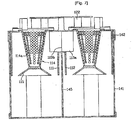
FIG. 7 illustrates a longitudinal section across a center of a primary cyclone unit in a left/right direction of a dust collecting device in accordance with a preferred embodiment of the present invention; -
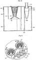
FIG. 8 illustrates a longitudinal section across a line B-B inFIG. 5 ; -
FIG. 9 illustrates a perspective view of the upper cover of the dust collecting device inFIG. 2 seen from above; and -
FIG. 10 illustrates a perspective view of an embodiment of a spiral flow forming member in a dust collecting device of the present invention. - Reference will now be made in detail to the preferred embodiments of the present invention, examples of which are illustrated in the accompanying drawings. Wherever possible, the same names and reference numbers will be used throughout the drawings to refer to the same or like parts, and repetitive description of which will be omitted.
- As one embodiment of a vacuum cleaner having a dust collecting device in accordance with a preferred embodiment of the present invention applied thereto, a canister type vacuum cleaner will be described.
- The vacuum cleaner includes a suction nozzle for drawing air containing foreign matters while moving along a floor to be cleaned, a cleaner body provided separate from the suction nozzle, and a connection pipe connected between the suction nozzle and the cleaner body for guiding contaminated air from the suction nozzle to the cleaner body.
- The suction nozzle has a predetermined size of nozzle suction opening in a bottom for drawing dust from the floor by air suction force generated at the cleaner body.
- Mounted inside of the cleaner body, there are an electric unit for controlling the vacuum cleaner, and a motor-fan assembly for drawing air.
- In more detail, the cleaner body has a hose connection portion at a front upper center for connecting the connection pipe thereto, wheels rotatably mounted at opposite sides of a rear of the cleaner body for smooth moving of the cleaner body on the floor, and a caster at a front portion of a bottom of the cleaner body, for changing a direction of the cleaner body.
- In the meantime, the cleaner body has the dust collecting device in accordance with a preferred embodiment of the present invention detachably mounted thereto for separating and collecting foreign matters, such as dust.
- Air from the dust collecting device passes a predetermined air discharge passage in the cleaner body, and the motor-fan assembly, and is discharged to an outside of the cleaner body.
- The dust collecting device may be mounted to a rear portion of the cleaner body or a front portion of the cleaner body.
- For this, the cleaner body has a dust collecting device mounting portion for mounting the dust collecting device.
- Between the hose connection portion and the dust collecting device mounting portion, there is a suction flow passage passed through a middle portion of the cleaner body.
- The
dust collecting device 100 in accordance with a preferred embodiment of the present invention will be described with reference to a case the dust collecting device is mounted to the rear portion of the cleaner body. -
FIG. 2 illustrates a perspective view of a dust collecting device in accordance with a preferred embodiment of the present invention, andFIG. 3 illustrates a plan view of a dust collecting device in accordance with a preferred embodiment of the present invention. - Referring to
FIGS 2 and 3 , thedust collecting device 100 in accordance with a preferred embodiment of the present invention includes aprimary cyclone unit 110 having twoprimary cyclones secondary cyclone unit 120 in a downstream of theprimary cyclones - The
primary cyclones secondary cyclone unit 120 also cleans the air again by the cyclone principle. - In the cyclone principle, foreign matters, such as dust, are separated from air circulating in a spiral by using a difference of centrifugal forces between the air and the dust.
- Referring to
FIGS 3 to 5 , it is preferable that asuction guide portion 113 is provided between theprimary cyclones primary cyclones - Preferably, the
suction guide portion 113 includes aguide surface 113a for guiding the air containing dust to inlets of the primary cyclones, respectively. - The
guide surface 113a has one side connected to an edge of an inlet of one of the primary cyclones, the other side connected to an edge of an inlet of the other the primary cyclones, and a middle portion projected toward an inside of thesuction guide portion 113 as it goes toward themiddle portion 113b from the one side and the other side the more. - In addition to this, the
suction guide portion 113 may have a split plate (not shown) on an inside thereof for splitting the air flowing toward theprimary cyclones suction guide portion 113 into two sides. - Moreover, the
dust collecting device 100 in accordance with a preferred embodiment of the present invention further includes adust collecting container 140 having theprimary cyclones dust storage portion 130 provided therein. - The primary
dust storage portion 130 stores dust separated at theprimary cyclone unit 110. - The
primary cyclones dust collecting container 140 such that axes thereof are arranged in an up/down direction. - It is preferable that each of the
primary cyclones inlet dust storage portion 130. - The foreign matters, such as dust, separated in the
primary cyclones dust storage portion 130 through the bottoms of theprimary cyclones - For this, each of the
primary cyclones - In more detail, it is preferable that each of the
primary cyclones primary cyclones - Each of the
primary cyclones dust collecting container 140. - It is preferable that the
dust collecting container 140 forms an exterior of the dust collecting device in accordance with a preferred embodiment of the present invention, and has an openable top portion. - In more detail, the
dust collecting container 140 includes acylindrical body 141 having an opened top, and anupper cover 142 for opening/closing the top end of the cylindrical body. - According to this, the
upper cover 142 is mounted on the top of thedust collecting container 140, openably. - It is preferable that the
primary cyclones upper cover 142, and outside circumferences close to the inside wall of thedust collecting container 140, for maximizing sizes of the primary cyclones. - The concept of "close"includes that the outside circumferences of the
primary cyclones dust collecting container 140, or there are small gaps between the outside circumferential surfaces of theprimary cyclones dust collecting container 140. - Of course, a portion of the outside wall of the
primary cyclones body 141 of the dust collecting container. - Referring to
FIG. 6 , theupper cover 142 hasoutlets 142a for discharging air cleaned at theprimary cyclones - For convenience of description, with reference to a state the
dust collecting device 100 is mounted to the cleaner body (not shown), a primary cyclone provided to a left side of thedust collecting container 140 is called as aleft side cyclone 111, and a primary cyclone provided to a right side of thedust collecting container 140 is called as aright side cyclone 112. - Referring to
FIGS 5 and7 , theinlet 111a to the left side cyclone is formed at a left side of the outside circumference of the left side cyclone, and theinlet 112a to the right side cyclone is formed at a right side of the outside circumference of the right side cyclone, such that theinlet 111a to the left side cyclone faces theinlet 112a to the right side cyclone. - The
guide surface 113a of the suction guide portion has a left end connected to a rear edge of theinlet 111a to the left side cyclone, a right end connected to a rear edge of theinlet 112a to the right side cyclone, and amiddle portion 113b projected forward the more as it goes to the middle the more. - In the meantime, the
dust collecting container 140 includes asuction pipe 143 having an inlet projected from an upper center of an outside circumferential surface, and an axis passing through a middle portion of theprimary cyclone unit 110. - When seen from an upper side of the
dust collecting container 140, the axis of thesuction pipe 143 divides theprimary cyclone unit 110 equally, and serves to guide the air containing dust to theprimary cyclone unit 110. - In more detail, a rear end of the
suction pipe 143 has opposite sidewalls each connected to an outside circumferential surface of theleft side cyclone 111 and an outside circumferential surface of theright side cyclone 112, both of which form inlets of thesuction guide portion 113, and a front end projected forward to a predetermined height from an upper center of thebody 141 of the dust collecting container, to form a portion of an inlet. - If the inlet of the
suction pipe 143 is formed in the upper center of the dust collectingcontainer body 141 thus, the suction flow passage of the cleaner body and thesuction pipe 143 are almost in a straight line, leading to reduce a flow resistance and a flow length, and improves air tightness between the suction flow passage and thesuction pipe 143. - In this instance, though the rear end of the
suction pipe 143 can be connected to a front edge of theinlet 111a to the left cyclone, and a front edge of theinlet 112a to the right side cyclone directly, it is preferable that a width between the front edge of theinlet 111a to the left cyclone, and the front edge of theinlet 112a to the right side cyclone is smaller than a width of thesuction pipe 143. - When the
dust collecting container 140 is seen from above, the axis of the suction pipe143 passes themiddle portion 113b of the guide surface to divide the entiredust collecting container 140 into a left side and a right side, equally. - In this instance, the axis of the
suction pipe 143 may be formed horizontally, or sloped downwardly at a predetermined angle as it goes toward a rear side the more. - In addition to this, it is preferable that each of the
primary cyclones air discharge member 114 therein. - In more detail, the
air discharge member 114 is in communication with theoutlets 142a of the primary cyclones, and has pass throughholes 114a of predetermined sizes in an outside circumferential surface for discharging air. - For this, a top end of the
air discharging member 114 is opened for enabling air discharge, and detachably connected to an edge of theoutlets 142a of the primary cyclones. - At a bottom end of the
air discharge member 114, there is a flypreventive member 115 having a shape with a horizontal sectional area which becomes the larger as it goes to a lower side the more, for minimizing fly of the dust by the spiral circulation in the primarydust storage portion 130. - The
air discharge member 114 may be cylindrical or have a shape with a sectional area across an axis direction which becomes the smaller as it goes toward a lower side the more. - In the meantime, the
primary cyclone unit 110 is provided to one side portion of thedust collecting container 140, and thesecondary cyclone unit 120 is provided to the other portion of thedust collecting container 140. - In the embodiment, the
secondary cyclone unit 120 is provided to a rear side of theprimary cyclone unit 110. Accordingly, theprimary cyclone unit 110 is provided to a front side of thedust collecting container 140, and thesecondary cyclone unit 120 is provided to the rear side. - The
secondary cyclone unit 120 will be described in more detail, with reference toFIGS 8 to 10 . - The
secondary cyclone unit 120 includes a plurality ofsecondary cyclones 121 provided to a rear side of thedust collecting container 140. - The
secondary cyclones 121 have vertical axes respectively, anddust outlets 121a at a bottom ends respectively. - Each of the
secondary cyclones 121 includes asecondary cyclone body 121b having a cylindrical shape or a shape with an area of a section perpendicular to an axis direction which becomes the smaller as it goes toward a lower side, and a spiral circulation forming member provided to thesecondary cyclone body 121b for forming a spiral circulation in thesecondary cyclone body 121b. - Of course, the
secondary cyclone body 121b may have a shape of a combination of the two shapes. For an example, thesecondary cyclone unit 121 may include a cylindrical upper body and a lower body at a lower end of the body, of a shape which has an area of a section perpendicular to an axis direction which becomes the smaller as it goes toward a lower side the more. - In this instance, a bottom end of the lower body is opened to form the
dust outlet 121a. - The spiral circulation forming member includes at least one
blade 121c provided to an inside of thesecondary cyclone body 121b. In this instance, the at least oneblade 121c is provided to an upper side of thesecondary cyclone body 121b. - In more detail, the at least one
blade 121c is provided to an outside circumferential surface of theair discharge pipe 122 to be inserted to the upper side of thesecondary cyclone body 121b. - It is preferable that the
air discharge pipe 122 serves to discharge the air cleaned at thesecondary cyclone 121, and is cylindrical. - In this instance, the
blade 121c may have an inside surface formed as one body with an outside circumferential surface of theair discharge pipe 122, and an outside surface formed as one body with an inside circumferential surface of thesecondary cyclone body 121b. - It is preferable that a plurality of the
blades 121c are provided to the outside circumferential surface of theair discharge pipe 122 at regular intervals in a circumferential direction of the air discharge pipe. - The
secondary cyclones 121 may be arranged in two rows on a rear side of the primary cyclones, or in one row along a circumferential direction of the dust collecting container on an inside of thedust collecting container 140 within a predetermined section. - In the meantime, at the other side of the
dust collecting container 140, i.e., a rear side of thedust collecting container 140, there is a secondarydust storage portion 150 separate from the primarydust storage portion 130 for storing dust separated at thesecondary cyclone unit 120. - In this instance, it is preferable that a portion of an outside wall of the primary dust storage portion forms a portion of an outside wall of the
dust collecting container 140, and a portion of an outside wall of the secondarydust storage portion 150 forms a portion of an outside wall of thedust collecting container 140. - More preferably, it is more preferable to maximize a capacity of the dust storage portion including the primary
dust storage portion 130 and the secondarydust storage portion 150 by making the outside wall of the primarydust storage portion 130 form a major portion of the outside wall of thedust collecting container 140, and the outside wall of the secondarydust storage portion 150 form rest of the outside wall of thedust collecting container 140. - For this, it is preferable that the
dust collecting container 140 includes an insidedust collecting container 140 which surrounds thesecondary cyclones 121, with a bottom end in close contact with a bottom of thedust collecting container 140. - In the embodiment, a rear outside wall of the inside
dust collecting container 144 forms a rear outside wall of thedust collecting container 140. - Of course, the rear outside wall of the inside
dust collecting container 144 may be in contact with the rear inside wall of thedust collecting container 140. - The bottom of the
dust collecting container 140 forms bottoms of the primarydust storage portion 130 and the secondarydust storage portion 150, and it is preferable that the bottom of thedust collecting container 140 is openable for easy discharge of dust from the primarydust storage portion 130 and the secondarydust storage portion 150. - Moreover, it is preferable that the primary
dust storage portion 130 has a bottom area larger than bottom areas of theprimary cyclones - In more detail, since the
primary cyclones dust collecting container 140 and thedust collecting container 140, the primarydust storage portion 130 has a bottom area larger than bottom areas of theprimary cyclones - According to this, the primary
dust storage portion 130 becomes to have a greater capacity. Moreover, since the dust falling down while circulating in a spiral spreads in a radial pattern toward the inside wall of the primarydust storage portion 130 by centrifugal force as the dust passes the bottom ends of theprimary cyclones air discharge members 114 by air discharged from theprimary cyclones - In addition to this, the
dust collecting container 140 further includes a partition wall for partitioning the primarydust storage portion 130. - The
partition wall 145 divides the primarydust storage portion 130 into a left sidedust storage portion 130, and a right side dust storage portion equally, so that the dust separated by theleft side cyclone 111 and the dust separated by theright side cyclone 112 are not mixed with each other. - Moreover, the
partition wall 145 prevents the spiral circulations of air formed by theleft side cyclone 111 and theright side cyclone 112 from giving an influence to each other, thereby preventing fly of the dust, and minimizing noise. - Moreover, in order to enable to determine an amount of dust stored in the primary
dust storage portion 130 and the secondarydust storage portion 150, it is preferable that the outside wall of thedust container 140 is formed of a material which can be see-through. - In the meantime, though not shown, on a top of the
upper cover 142, there is a cap provided thereto for forming an air flow chamber to make air from theprimary cyclones secondary cyclones 121. - It is preferable that the cap is openably provided to the
upper cover 142, and has a plurality of air discharge holes in a rear side connected to theair discharge pipes 122. - The operation of the vacuum cleaner having the
dust collecting device 100 of the present invention applied thereto will be described. - Upon putting the vacuum cleaner into operation, external contaminated air is introduced to the
primary cyclones suction pipe 143, and thesuction guide portion 113. - In more detail, the air introduced to the
suction guide portion 113 through thesuction pipe 143 is guided by the inside walls of theprimary cyclones primary cyclones - According to this, comparatively heavy and large particles of the dust are separated by the cyclone principle, fall down, and stored in the primary
dust storage portion 130. Fly of the dust stored in the primarydust storage portion 130 is prevented by the flypreventive members 115. - The air having the comparatively large particles separated therefrom is discharged to an upper side of the
upper cover 142 through theair discharge member 114 and theoutlets 142a, and introduced to the plurality ofsecondary cyclones 121 to pass through a dust separating step, again. - In this instance, the
blades 121c form a spiral circulation of air inside of thesecondary cyclones 121. - The air cleaned again by the
secondary cyclones 121 is discharged through theair discharge pipe 122, passes a predetermined air discharge flow passage in the cleaner body and the motor-fan assembly, and is discharged to an outside of the cleaner body. - In the meantime, the dust collecting device of the present invention is applicable both to the canister type vacuum cleaner, and the upright type vacuum cleaner.
- Thus, it is intended that the present invention covers the modifications and variations of this invention provided they come within the scope of the appended claims and their equivalents.
- The dust collecting device of the present invention having the foregoing design has the following advantages.
- First, the parallel arrangement of the two primary cyclones improves a dust collecting performance of the primary cyclone unit which separates a major portion of the dust, to improve a performance of the dust collecting device, on the whole.
- Second, the provision of the suction pipe for guiding air to the two parallel primary cyclones improves air tightness to the cleaner body, and enables to fabricate easily.
- Third, the sectional area of the dust storage portion formed larger than the sectional area of the bottom of the cyclone permits to minimize an influence of discharging air to the dust, thereby improving a dust separating performance.
- Fourth, the provision of the primary dust storage portion adjacent to the secondary dust storage portion in the dust collecting container permits easy cleaning of the dust container, and easy removal of the dust.
- Fifth, the easy determination of the amount of dust in the primary dust storage portion which stores a major portion of dust permits easy selection of a time for emptying the dust collecting container.
- Sxth, the provision of the primary cyclone unit with two parallel cyclones on one side of an inside of the dust collecting container of a predetermined shape, and the provision of the plurality of secondary cyclones on the other side of the inside of the dust collecting container permits to fabricate the dust collecting device compact, on the whole.
Claims (20)
- A dust collecting device (100) for a vacuum cleaner comprising:- a primary cyclone unit (110) for separating dust from air introduced therein by a cyclone principle; and- a secondary cyclone unit (120) at a downstream of the primary cyclone unit (110) for cleaning the air again by the cyclone principle,wherein the primary cyclone unit (110) has two parallel primary cyclones (111, 112),
the primary cyclone unit (110) further includes a suction guide portion (113) between the primary cyclones (111, 112) for guiding the air containing dust to the primary cyclones (111, 112), wherein the suction guide portion (113) includes a guide surface (113a) for guiding the air containing dust to inlets to the primary cyclones (111, 112),
wherein the guide surface (113a) has one side connected to an edge of the inlet of one of the primary cyclones (111, 112), the other side connected to an edge of the inlet of the other the primary cyclones, and a middle portion (113b) projected toward an inside of the suction guide portion (113) as it goes toward the middle portion (113b) from the one side and the other side the more. - The dust collecting device as claimed in claim 1, further comprising a dust collecting container (140) having the primary cyclones (111, 112) and a primary dust storage portion (130) for, storing dust separated by the primary cyclones (111, 112).
- The dust collecting device as claimed in claim 2, wherein each of the primary cyclones (111, 112) is provided in the dust collecting container (140) such that an axis thereof lies in an up/down direction, having an inlet (111a, 112a) in an upper outside circumferential surface, and a bottom end spaced a predetermined distance from a bottom of the primary dust storage portion (130), and designed to discharge the dust to the primary dust storage portion (130) through the bottom of each of the primary cyclones (111, 112).
- The dust collecting device as claimed in claim 3, wherein each of the primary cyclones (111, 112) has a top end connected to an upper cover (142) openably provided on a top of the dust collecting container (140), and an outside circumferential surface adjacent to an inside wall of the dust collecting container (140).
- The dust collecting device as claimed in claim 3, wherein the primary dust storage portion (130) has a bottom area larger than bottom areas of the primary cyclones (111, 112).
- The dust collecting device as claimed in claim 3, wherein the dust collecting container (140) further includes a partition wall (145) or dividing the primary dust storage portion (130) into a portion for storing dust separated by one of the primary cyclones (111, 112), and a portion for storing dust separated by the other one of the primary cyclones (111, 112).
- The dust collecting device as claimed in claim 3, wherein the dust collecting container (140) includes a suction pipe (143) for guiding air containing dust to the primary cyclone unit (110), wherein the suction pipe (143) has an inlet projected from an upper center of an outside circumferential surface of the dust collecting container (140), and an axis passing through a middle portion (113b) of the primary cyclone unit (110) when seen from above the dust collecting container (140).
- The dust collecting device as claimed in claim 3, further comprising a hollow air discharge member (114) in each of the primary cyclones (111, 112), the air discharge member (114) being in communication with the outlet of the primary cyclone (111, 112) and having pass through holes (114a) of predetermined sizes in an outside circumferential surface for discharging air.
- The dust collecting device as claimed in claim 2, wherein the primary cyclone unit (110) is provided to one side of the dust collecting container (140), and the secondary cyclone unit (120) includes a plurality of secondary cyclones (121) provided to the other side of the dust collecting container (140).
- The dust collecting device as claimed in claim 9, wherein the secondary cyclones (121) have axes each formed in an up/down direction, and bottoms each with a dust outlet.
- The dust collecting device as claimed in claim 10, wherein a secondary dust storage portion (150) is provided under the secondary cyclones (121) on the other side of the dust collecting container (140) separate from the primary dust storage portion (130) for storing dust separated by the secondary cyclone unit (120).
- The dust collecting device as claimed in claim 11, wherein the dust collecting container (140) includes an inside dust collecting container (144) on the other side of the dust collecting container (140) to surround the secondary cyclones (121) to form the secondary dust storage portion (150).
- The dust collecting device as claimed in claim 12, wherein the dust collecting container (140) has an openable bottom which forms bottoms of the primary dust storage portion (130) and the secondary dust storage portion (150).
- The dust collecting device as claimed in claim 11, wherein the dust collecting container (140) has an outside wall formed of a material which can be see-through for enabling to determine dust amounts in the primary dust storage portion (130) and the secondary dust storage portion (150).
- The dust collecting device as claimed in claim 9, wherein each of the secondary cyclones (121) includes:a secondary cyclone body (121b) having an inlet at a top, anda spiral circulation forming member provided to an inside of the secondary cyclone body (121b) for forming a spiral circulation in the secondary cyclone body.
- The dust collecting device as claimed in claim 15, wherein the spiral circulation forming member includes at least one blade (121c) provided to an upper portion of the secondary cyclone body (121b).
- The dust collecting device as claimed in claim 16, wherein the at least one blade (121c) is provided to an outside circumferential surface of an air discharge pipe (122) inserted in an upper portion of the secondary cyclone body (121b) for guiding air from the secondary cyclone body (121b).
- The dust collecting device as claimed in claim 9, wherein the secondary cyclones (121) are arranged at least in two rows on one side of the dust collecting container (140).
- The dust collecting device as claimed in claim 9, wherein the secondary cyclones (121) are arranged in one row along a circumferential direction of the dust collecting container (140) on an inside of the dust collecting container (140) within a predetermined section.
- The dust collecting device as claimed in claim 9, wherein the primary cyclones (111, 112) are provided in the same size on a front side of the dust collecting container (140) side by side, and the secondary cyclones (121) are provided to a rear side of the dust collecting container (140).
Applications Claiming Priority (1)
| Application Number | Priority Date | Filing Date | Title |
|---|---|---|---|
| PCT/KR2005/002688 WO2007021043A1 (en) | 2005-08-17 | 2005-08-17 | Dust collecting device for vacuum cleaner |
Publications (3)
| Publication Number | Publication Date |
|---|---|
| EP1915084A1 EP1915084A1 (en) | 2008-04-30 |
| EP1915084B1 EP1915084B1 (en) | 2015-04-22 |
| EP1915084B2 true EP1915084B2 (en) | 2018-04-25 |
Family
ID=37757686
Family Applications (1)
| Application Number | Title | Priority Date | Filing Date |
|---|---|---|---|
| EP05780588.9A Not-in-force EP1915084B2 (en) | 2005-08-17 | 2005-08-17 | Dust collecting device for vacuum cleaner |
Country Status (5)
| Country | Link |
|---|---|
| US (1) | US7892305B2 (en) |
| EP (1) | EP1915084B2 (en) |
| KR (1) | KR101003417B1 (en) |
| CN (1) | CN101262806B (en) |
| WO (1) | WO2007021043A1 (en) |
Families Citing this family (77)
| Publication number | Priority date | Publication date | Assignee | Title |
|---|---|---|---|---|
| GB2436281B (en) | 2006-03-24 | 2011-07-20 | Hoover Ltd | Cyclonic vacuum cleaner |
| KR20080000188A (en) * | 2006-06-27 | 2008-01-02 | 엘지전자 주식회사 | Dust collecting unit for vaccum cleaner |
| DE102006036943A1 (en) * | 2006-08-08 | 2008-02-14 | Hydac Process Technology Gmbh | filter means |
| CA2599303A1 (en) | 2007-08-29 | 2009-02-28 | Gbd Corp. | Surface cleaning apparatus |
| US9192269B2 (en) | 2006-12-15 | 2015-11-24 | Omachron Intellectual Property Inc. | Surface cleaning apparatus |
| US9888817B2 (en) | 2014-12-17 | 2018-02-13 | Omachron Intellectual Property Inc. | Surface cleaning apparatus |
| US20210401246A1 (en) | 2016-04-11 | 2021-12-30 | Omachron Intellectual Property Inc. | Surface cleaning apparatus |
| US10165912B2 (en) | 2006-12-15 | 2019-01-01 | Omachron Intellectual Property Inc. | Surface cleaning apparatus |
| US11857142B2 (en) | 2006-12-15 | 2024-01-02 | Omachron Intellectual Property Inc. | Surface cleaning apparatus having an energy storage member and a charger for an energy storage member |
| US7941895B2 (en) * | 2007-12-19 | 2011-05-17 | G.B.D. Corp. | Configuration of a cyclone assembly and surface cleaning apparatus having same |
| KR101472835B1 (en) * | 2008-02-15 | 2014-12-17 | 삼성전자주식회사 | Cyclone Collecting Apparatus for Vacuum Cleaner |
| US9265395B2 (en) | 2010-03-12 | 2016-02-23 | Omachron Intellectual Property Inc. | Surface cleaning apparatus |
| US10722086B2 (en) | 2017-07-06 | 2020-07-28 | Omachron Intellectual Property Inc. | Handheld surface cleaning apparatus |
| US9433332B2 (en) | 2013-02-27 | 2016-09-06 | Omachron Intellectual Property Inc. | Surface cleaning apparatus |
| US9211044B2 (en) | 2011-03-04 | 2015-12-15 | Omachron Intellectual Property Inc. | Compact surface cleaning apparatus |
| US8875340B2 (en) | 2010-03-12 | 2014-11-04 | G.B.D. Corp. | Surface cleaning apparatus with enhanced operability |
| US8739359B2 (en) | 2011-03-03 | 2014-06-03 | G.B.D. Corp. | Configuration of a surface cleaning apparatus |
| US8973212B2 (en) | 2011-03-03 | 2015-03-10 | G.B.D. Corp. | Filter housing construction for a surface cleaning apparatus |
| US8813306B2 (en) | 2011-03-03 | 2014-08-26 | G.B.D. Corp. | Openable side compartments for a surface cleaning apparatus |
| US8763202B2 (en) | 2011-03-03 | 2014-07-01 | G.B.D. Corp. | Cyclone chamber and dirt collection assembly for a surface cleaning apparatus |
| US8739357B2 (en) | 2011-03-03 | 2014-06-03 | G.B.D. Corp | Filter construction for a surface cleaning apparatus |
| US8973214B2 (en) * | 2011-03-03 | 2015-03-10 | G.B.D. Corp. | Cyclone chamber and dirt collection assembly for a surface cleaning apparatus |
| US8769767B2 (en) | 2011-03-03 | 2014-07-08 | G.B.D. Corp. | Removable cyclone chamber and dirt collection assembly for a surface cleaning apparatus |
| US8978198B2 (en) | 2011-03-03 | 2015-03-17 | G.B.D. Corp. | Filter housing for a surface cleaning apparatus |
| US9101252B2 (en) | 2011-03-03 | 2015-08-11 | G.B.D. Corp. | Configuration of a surface cleaning apparatus |
| US8869345B2 (en) | 2011-03-03 | 2014-10-28 | G.B.D. Corp. | Canister vacuum cleaner |
| GB2490695B (en) * | 2011-05-11 | 2015-01-14 | Dyson Technology Ltd | A surface treating appliance |
| GB2490693B (en) | 2011-05-11 | 2014-12-17 | Dyson Technology Ltd | A cyclonic surface treating appliance with multiple cyclones |
| GB2490696B (en) | 2011-05-11 | 2014-12-17 | Dyson Technology Ltd | A cyclonic surface treating appliance with multiple cyclones |
| GB2490697B (en) | 2011-05-11 | 2015-01-14 | Dyson Technology Ltd | A surface treating appliance |
| GB2490694B (en) * | 2011-05-11 | 2015-01-14 | Dyson Technology Ltd | A surface treating appliance |
| GB2492744B (en) | 2011-05-11 | 2014-12-24 | Dyson Technology Ltd | A multi-cyclonic surface treating appliance |
| GB2490692B (en) | 2011-05-11 | 2014-12-17 | Dyson Technology Ltd | A cyclonic surface treating appliance with multiple cyclones |
| GB2492743B (en) | 2011-05-11 | 2015-01-14 | Dyson Technology Ltd | A surface treating appliance |
| GB2499620B (en) * | 2012-02-21 | 2019-05-22 | Caltec Production Solutions Ltd | Fluid separator |
| JP6050946B2 (en) * | 2012-04-16 | 2016-12-21 | 日立アプライアンス株式会社 | Electric vacuum cleaner |
| US9320401B2 (en) | 2013-02-27 | 2016-04-26 | Omachron Intellectual Property Inc. | Surface cleaning apparatus |
| US9027198B2 (en) | 2013-02-27 | 2015-05-12 | G.B.D. Corp. | Surface cleaning apparatus |
| US9591958B2 (en) | 2013-02-27 | 2017-03-14 | Omachron Intellectual Property Inc. | Surface cleaning apparatus |
| US9295995B2 (en) | 2013-02-28 | 2016-03-29 | Omachron Intellectual Property Inc. | Cyclone such as for use in a surface cleaning apparatus |
| US9820621B2 (en) | 2013-02-28 | 2017-11-21 | Omachron Intellectual Property Inc. | Surface cleaning apparatus |
| US9227201B2 (en) | 2013-02-28 | 2016-01-05 | Omachron Intellectual Property Inc. | Cyclone such as for use in a surface cleaning apparatus |
| US9204773B2 (en) | 2013-03-01 | 2015-12-08 | Omachron Intellectual Property Inc. | Surface cleaning apparatus |
| US9161669B2 (en) | 2013-03-01 | 2015-10-20 | Omachron Intellectual Property Inc. | Surface cleaning apparatus |
| US20140237764A1 (en) | 2013-02-28 | 2014-08-28 | G.B.D. Corp. | Cyclone such as for use in a surface cleaning apparatus |
| US9227151B2 (en) | 2013-02-28 | 2016-01-05 | Omachron Intellectual Property Inc. | Cyclone such as for use in a surface cleaning apparatus |
| US9326652B2 (en) | 2013-02-28 | 2016-05-03 | Omachron Intellectual Property Inc. | Surface cleaning apparatus |
| US9427126B2 (en) | 2013-03-01 | 2016-08-30 | Omachron Intellectual Property Inc. | Surface cleaning apparatus |
| US9238235B2 (en) | 2013-02-28 | 2016-01-19 | Omachron Intellectual Property Inc. | Cyclone such as for use in a surface cleaning apparatus |
| US9451855B2 (en) | 2013-02-28 | 2016-09-27 | Omachron Intellectual Property Inc. | Surface cleaning apparatus |
| US9585530B2 (en) | 2014-07-18 | 2017-03-07 | Omachron Intellectual Property Inc. | Portable surface cleaning apparatus |
| US9420925B2 (en) | 2014-07-18 | 2016-08-23 | Omachron Intellectual Property Inc. | Portable surface cleaning apparatus |
| US9314139B2 (en) | 2014-07-18 | 2016-04-19 | Omachron Intellectual Property Inc. | Portable surface cleaning apparatus |
| US9451853B2 (en) | 2014-07-18 | 2016-09-27 | Omachron Intellectual Property Inc. | Portable surface cleaning apparatus |
| US10251519B2 (en) | 2014-12-17 | 2019-04-09 | Omachron Intellectual Property Inc. | Surface cleaning apparatus |
| US10136778B2 (en) | 2014-12-17 | 2018-11-27 | Omachron Intellectual Property Inc. | Surface cleaning apparatus |
| KR102202268B1 (en) * | 2014-12-17 | 2021-01-13 | 엘지전자 주식회사 | Dust collector for vacuum cleaner |
| US11950745B2 (en) | 2014-12-17 | 2024-04-09 | Omachron Intellectual Property Inc. | Surface cleaning apparatus |
| CN104545695B (en) * | 2015-01-28 | 2016-08-31 | 莱克电气股份有限公司 | A kind of two grades of dust and gas isolating constructions and comprise the dirt cup of this structure |
| US10456002B2 (en) | 2016-12-22 | 2019-10-29 | Irobot Corporation | Cleaning bin for cleaning robot |
| JP6968224B2 (en) * | 2016-12-22 | 2021-11-17 | アイロボット・コーポレーション | Cleaning bin for cleaning robots |
| BE1025205B1 (en) * | 2017-04-27 | 2018-12-11 | Atlas Copco Airpower Naamloze Vennootschap | Device for separating liquid from a gas stream in a liquid-injected compressor and method thereof |
| US11730327B2 (en) | 2020-03-18 | 2023-08-22 | Omachron Intellectual Property Inc. | Surface cleaning apparatus with removable air treatment assembly |
| US11445878B2 (en) | 2020-03-18 | 2022-09-20 | Omachron Intellectual Property Inc. | Surface cleaning apparatus with removable air treatment member assembly |
| US10842330B2 (en) | 2017-07-06 | 2020-11-24 | Omachron Intellectual Property Inc. | Handheld surface cleaning apparatus |
| US11766156B2 (en) | 2020-03-18 | 2023-09-26 | Omachron Intellectual Property Inc. | Surface cleaning apparatus with removable air treatment member assembly |
| US10506904B2 (en) | 2017-07-06 | 2019-12-17 | Omachron Intellectual Property Inc. | Handheld surface cleaning apparatus |
| US10750913B2 (en) | 2017-07-06 | 2020-08-25 | Omachron Intellectual Property Inc. | Handheld surface cleaning apparatus |
| US11666193B2 (en) | 2020-03-18 | 2023-06-06 | Omachron Intellectual Property Inc. | Surface cleaning apparatus with removable air treatment member assembly |
| US10702113B2 (en) | 2017-07-06 | 2020-07-07 | Omachron Intellectual Property Inc. | Handheld surface cleaning apparatus |
| US10537216B2 (en) | 2017-07-06 | 2020-01-21 | Omachron Intellectual Property Inc. | Handheld surface cleaning apparatus |
| US10631693B2 (en) | 2017-07-06 | 2020-04-28 | Omachron Intellectual Property Inc. | Handheld surface cleaning apparatus |
| US11013378B2 (en) | 2018-04-20 | 2021-05-25 | Omachon Intellectual Property Inc. | Surface cleaning apparatus |
| US11006799B2 (en) * | 2018-08-13 | 2021-05-18 | Omachron Intellectual Property Inc. | Cyclonic air treatment member and surface cleaning apparatus including the same |
| US11154169B2 (en) | 2018-08-13 | 2021-10-26 | Omachron Intellectual Property Inc. | Cyclonic air treatment member and surface cleaning apparatus including the same |
| US11013384B2 (en) * | 2018-08-13 | 2021-05-25 | Omachron Intellectual Property Inc. | Cyclonic air treatment member and surface cleaning apparatus including the same |
| US11192122B2 (en) * | 2018-08-13 | 2021-12-07 | Omachron Intellectual Property Inc. | Cyclonic air treatment member and surface cleaning apparatus including the same |
Citations (6)
| Publication number | Priority date | Publication date | Assignee | Title |
|---|---|---|---|---|
| SE9601771L (en) † | 1996-05-09 | 1997-01-22 | Electrolux Ab | Cyclone separator for a vacuum cleaner |
| US20020194993A1 (en) † | 2001-06-22 | 2002-12-26 | Gen Ni Zu | Cyclone and dust filter vacuum cleaner |
| CN2647434Y (en) † | 2003-05-12 | 2004-10-13 | 姜大志 | Efficient energy-saving cyclone dust collector |
| US20050172584A1 (en) † | 2004-02-11 | 2005-08-11 | Samsung Gwangju Electronics Co., Ltd | Cyclone dust-collector |
| EP1707096A2 (en) † | 2005-03-29 | 2006-10-04 | Samsung Gwangju Electronics Co., Ltd. | Multi-cyclone dust collecting apparatus |
| WO2006125945A1 (en) † | 2005-05-27 | 2006-11-30 | Dyson Technology Limited | Cyclonic separating apparatus |
Family Cites Families (27)
| Publication number | Priority date | Publication date | Assignee | Title |
|---|---|---|---|---|
| DE60045814D1 (en) * | 1999-02-24 | 2011-05-19 | Lg Electronics Inc | VACUUM CLEANER WITH CYCLONE.AUMINATOR |
| US6673133B2 (en) * | 2000-06-02 | 2004-01-06 | Uop Llc | Cyclone for separating fine solid particles from a gas stream |
| CN2453827Y (en) | 2000-12-27 | 2001-10-17 | 倪祖根 | Split wirlwind dust-filtering device of cleaner |
| GB0104668D0 (en) | 2001-02-24 | 2001-04-11 | Dyson Ltd | Cyclonic separating apparatus |
| CN2478526Y (en) | 2001-03-17 | 2002-02-27 | 广东美的集团股份有限公司 | Centrifugal separating dust-collecting device for vacuum suction cleaner |
| US6576029B2 (en) * | 2001-06-13 | 2003-06-10 | National Tank Company | System for separating an entrained liquid component from a gas stream |
| DE10142701A1 (en) * | 2001-08-31 | 2003-04-03 | Mann & Hummel Filter | Multi-cell cyclone and process for its production |
| NO315788B1 (en) * | 2001-10-18 | 2003-10-27 | Consept As | Vertically oriented separator for removing liquid droplets from a gas stream |
| JP4131927B2 (en) | 2002-10-15 | 2008-08-13 | 株式会社東芝 | Vacuum cleaner |
| GB2399780A (en) | 2003-03-28 | 2004-09-29 | Dyson Ltd | Arrangement of cyclones for noise damping |
| GB2406067B (en) | 2003-09-08 | 2006-11-08 | Samsung Kwangju Electronics Co | Cyclonic dust-separating apparatus |
| KR100536504B1 (en) * | 2003-09-09 | 2005-12-14 | 삼성광주전자 주식회사 | A cyclone separating apparatus and vacumm cleaner equipped whth such a device |
| KR100592098B1 (en) * | 2004-02-11 | 2006-06-22 | 삼성광주전자 주식회사 | Cyclone Dust Collector of Vacuum Cleaner |
| US7309368B2 (en) * | 2004-02-11 | 2007-12-18 | Samsung Gwangju Electronics Co., Ltd. | Cyclone dust-collecting apparatus |
| KR100549990B1 (en) * | 2004-04-16 | 2006-02-08 | 삼성광주전자 주식회사 | Dust collecting apparatus for vacuum cleaner |
| KR100601896B1 (en) | 2004-05-12 | 2006-07-19 | 삼성광주전자 주식회사 | Cyclone separating apparatus and vacuum cleaner |
| KR100533830B1 (en) * | 2004-05-14 | 2005-12-07 | 삼성광주전자 주식회사 | Multi cyclone dust collecting apparatus |
| KR20060018017A (en) * | 2004-08-23 | 2006-02-28 | 엘지전자 주식회사 | Dust and dirt collecting unit for vacuum cleaner |
| US7419522B2 (en) * | 2005-03-18 | 2008-09-02 | Euro-Pro Operating, Llc | Dirt separation and collection assembly for vacuum cleaner |
| KR100560967B1 (en) * | 2005-01-14 | 2006-03-15 | 삼성광주전자 주식회사 | A cyclone dust-separating apparatus |
| KR100645375B1 (en) * | 2005-01-31 | 2006-11-14 | 삼성광주전자 주식회사 | Cyclone dust collecting apparatus having dust counterflow prevent member |
| US7410516B2 (en) * | 2005-03-17 | 2008-08-12 | Royal Appliance Mfg. Co. | Twin cyclone vacuum cleaner |
| KR100611067B1 (en) | 2005-04-18 | 2006-08-10 | 삼성광주전자 주식회사 | Cyclone dust collecting apparatus for a vacuum cleaner and vacuum cleaner having the same |
| KR100647197B1 (en) | 2005-06-14 | 2006-11-23 | 삼성광주전자 주식회사 | Multi cyclone dust collecting apparatus |
| EP1915083B1 (en) | 2005-08-17 | 2015-03-18 | LG Electronics Inc. | Dust collecting device for vacuum cleaner |
| EP2554090B1 (en) * | 2005-12-22 | 2014-04-09 | Diversey, Inc. | Squeegee assembly for a floor cleaning machine |
| GB2436281B (en) | 2006-03-24 | 2011-07-20 | Hoover Ltd | Cyclonic vacuum cleaner |
-
2005
- 2005-08-17 KR KR20087003509A patent/KR101003417B1/en active IP Right Grant
- 2005-08-17 WO PCT/KR2005/002688 patent/WO2007021043A1/en active Application Filing
- 2005-08-17 US US11/990,400 patent/US7892305B2/en active Active
- 2005-08-17 CN CN2005800513228A patent/CN101262806B/en not_active Expired - Fee Related
- 2005-08-17 EP EP05780588.9A patent/EP1915084B2/en not_active Not-in-force
Patent Citations (6)
| Publication number | Priority date | Publication date | Assignee | Title |
|---|---|---|---|---|
| SE9601771L (en) † | 1996-05-09 | 1997-01-22 | Electrolux Ab | Cyclone separator for a vacuum cleaner |
| US20020194993A1 (en) † | 2001-06-22 | 2002-12-26 | Gen Ni Zu | Cyclone and dust filter vacuum cleaner |
| CN2647434Y (en) † | 2003-05-12 | 2004-10-13 | 姜大志 | Efficient energy-saving cyclone dust collector |
| US20050172584A1 (en) † | 2004-02-11 | 2005-08-11 | Samsung Gwangju Electronics Co., Ltd | Cyclone dust-collector |
| EP1707096A2 (en) † | 2005-03-29 | 2006-10-04 | Samsung Gwangju Electronics Co., Ltd. | Multi-cyclone dust collecting apparatus |
| WO2006125945A1 (en) † | 2005-05-27 | 2006-11-30 | Dyson Technology Limited | Cyclonic separating apparatus |
Also Published As
| Publication number | Publication date |
|---|---|
| KR20080032180A (en) | 2008-04-14 |
| KR101003417B1 (en) | 2010-12-23 |
| US7892305B2 (en) | 2011-02-22 |
| WO2007021043A1 (en) | 2007-02-22 |
| CN101262806B (en) | 2010-10-13 |
| CN101262806A (en) | 2008-09-10 |
| EP1915084A1 (en) | 2008-04-30 |
| US20090205298A1 (en) | 2009-08-20 |
| EP1915084B1 (en) | 2015-04-22 |
Similar Documents
| Publication | Publication Date | Title |
|---|---|---|
| EP1915084B2 (en) | Dust collecting device for vacuum cleaner | |
| EP1915083B1 (en) | Dust collecting device for vacuum cleaner | |
| US7753976B2 (en) | Dust collecting device for vacuum cleaner | |
| US7935162B2 (en) | Dust collecting device for vacuum cleaner | |
| EP1772090B1 (en) | Multi-cyclone dust collection apparatus | |
| EP1969986B1 (en) | Dust separating apparatus of vacuum cleaner | |
| EP1361815B1 (en) | Vacuum cleaner | |
| US7501002B2 (en) | Cyclone dust separator and a vacuum cleaner having the same | |
| EP2170144B1 (en) | Dust separation apparatus of vacuum cleaner | |
| EP1938733A1 (en) | Cyclonic separation apparatus and vacuum cleaner having such a separation apparatus | |
| EP1774890B1 (en) | A multi cyclone dust collector for a vacuum cleaner | |
| KR101065968B1 (en) | Dust collecting apparatus of vacuum cleaner | |
| EP2142065B1 (en) | Dust separating apparatus of vacuum cleaner | |
| KR100546627B1 (en) | Dust collector for vacuum cleaner | |
| KR100546628B1 (en) | Dust collector for vacuum cleaner | |
| KR100556443B1 (en) | Dust collector for vacuum cleaner |
Legal Events
| Date | Code | Title | Description |
|---|---|---|---|
| PUAI | Public reference made under article 153(3) epc to a published international application that has entered the european phase |
Free format text: ORIGINAL CODE: 0009012 |
|
| 17P | Request for examination filed |
Effective date: 20080206 |
|
| AK | Designated contracting states |
Kind code of ref document: A1 Designated state(s): AT BE BG CH CY CZ DE DK EE ES FI FR GB GR HU IE IS IT LI LT LU LV MC NL PL PT RO SE SI SK TR |
|
| RIN1 | Information on inventor provided before grant (corrected) |
Inventor name: HYUN, KIE TAK,C/O DAC RESEARCH INSTITUTE, LG ELECT Inventor name: JEONG, KYEONG SEON,C/O DAC RESEARCH INSTITUTE, LG Inventor name: SON, YOUNG BOK Inventor name: KIM, IL JOONG |
|
| 17Q | First examination report despatched |
Effective date: 20091020 |
|
| DAX | Request for extension of the european patent (deleted) | ||
| GRAP | Despatch of communication of intention to grant a patent |
Free format text: ORIGINAL CODE: EPIDOSNIGR1 |
|
| INTG | Intention to grant announced |
Effective date: 20141113 |
|
| RAP1 | Party data changed (applicant data changed or rights of an application transferred) |
Owner name: LG ELECTRONICS INC. |
|
| GRAS | Grant fee paid |
Free format text: ORIGINAL CODE: EPIDOSNIGR3 |
|
| GRAA | (expected) grant |
Free format text: ORIGINAL CODE: 0009210 |
|
| AK | Designated contracting states |
Kind code of ref document: B1 Designated state(s): AT BE BG CH CY CZ DE DK EE ES FI FR GB GR HU IE IS IT LI LT LU LV MC NL PL PT RO SE SI SK TR |
|
| REG | Reference to a national code |
Ref country code: GB Ref legal event code: FG4D |
|
| REG | Reference to a national code |
Ref country code: CH Ref legal event code: EP |
|
| REG | Reference to a national code |
Ref country code: AT Ref legal event code: REF Ref document number: 722672 Country of ref document: AT Kind code of ref document: T Effective date: 20150515 |
|
| REG | Reference to a national code |
Ref country code: IE Ref legal event code: FG4D |
|
| REG | Reference to a national code |
Ref country code: DE Ref legal event code: R096 Ref document number: 602005046404 Country of ref document: DE Effective date: 20150603 |
|
| REG | Reference to a national code |
Ref country code: NL Ref legal event code: VDEP Effective date: 20150422 |
|
| REG | Reference to a national code |
Ref country code: AT Ref legal event code: MK05 Ref document number: 722672 Country of ref document: AT Kind code of ref document: T Effective date: 20150422 |
|
| REG | Reference to a national code |
Ref country code: LT Ref legal event code: MG4D |
|
| PG25 | Lapsed in a contracting state [announced via postgrant information from national office to epo] |
Ref country code: NL Free format text: LAPSE BECAUSE OF FAILURE TO SUBMIT A TRANSLATION OF THE DESCRIPTION OR TO PAY THE FEE WITHIN THE PRESCRIBED TIME-LIMIT Effective date: 20150422 |
|
| PG25 | Lapsed in a contracting state [announced via postgrant information from national office to epo] |
Ref country code: LT Free format text: LAPSE BECAUSE OF FAILURE TO SUBMIT A TRANSLATION OF THE DESCRIPTION OR TO PAY THE FEE WITHIN THE PRESCRIBED TIME-LIMIT Effective date: 20150422 Ref country code: ES Free format text: LAPSE BECAUSE OF FAILURE TO SUBMIT A TRANSLATION OF THE DESCRIPTION OR TO PAY THE FEE WITHIN THE PRESCRIBED TIME-LIMIT Effective date: 20150422 Ref country code: FI Free format text: LAPSE BECAUSE OF FAILURE TO SUBMIT A TRANSLATION OF THE DESCRIPTION OR TO PAY THE FEE WITHIN THE PRESCRIBED TIME-LIMIT Effective date: 20150422 Ref country code: PT Free format text: LAPSE BECAUSE OF FAILURE TO SUBMIT A TRANSLATION OF THE DESCRIPTION OR TO PAY THE FEE WITHIN THE PRESCRIBED TIME-LIMIT Effective date: 20150824 |
|
| PG25 | Lapsed in a contracting state [announced via postgrant information from national office to epo] |
Ref country code: IS Free format text: LAPSE BECAUSE OF FAILURE TO SUBMIT A TRANSLATION OF THE DESCRIPTION OR TO PAY THE FEE WITHIN THE PRESCRIBED TIME-LIMIT Effective date: 20150822 Ref country code: AT Free format text: LAPSE BECAUSE OF FAILURE TO SUBMIT A TRANSLATION OF THE DESCRIPTION OR TO PAY THE FEE WITHIN THE PRESCRIBED TIME-LIMIT Effective date: 20150422 Ref country code: LV Free format text: LAPSE BECAUSE OF FAILURE TO SUBMIT A TRANSLATION OF THE DESCRIPTION OR TO PAY THE FEE WITHIN THE PRESCRIBED TIME-LIMIT Effective date: 20150422 Ref country code: GR Free format text: LAPSE BECAUSE OF FAILURE TO SUBMIT A TRANSLATION OF THE DESCRIPTION OR TO PAY THE FEE WITHIN THE PRESCRIBED TIME-LIMIT Effective date: 20150723 |
|
| REG | Reference to a national code |
Ref country code: DE Ref legal event code: R026 Ref document number: 602005046404 Country of ref document: DE |
|
| PG25 | Lapsed in a contracting state [announced via postgrant information from national office to epo] |
Ref country code: DK Free format text: LAPSE BECAUSE OF FAILURE TO SUBMIT A TRANSLATION OF THE DESCRIPTION OR TO PAY THE FEE WITHIN THE PRESCRIBED TIME-LIMIT Effective date: 20150422 Ref country code: EE Free format text: LAPSE BECAUSE OF FAILURE TO SUBMIT A TRANSLATION OF THE DESCRIPTION OR TO PAY THE FEE WITHIN THE PRESCRIBED TIME-LIMIT Effective date: 20150422 |
|
| PLBI | Opposition filed |
Free format text: ORIGINAL CODE: 0009260 |
|
| PLAX | Notice of opposition and request to file observation + time limit sent |
Free format text: ORIGINAL CODE: EPIDOSNOBS2 |
|
| PG25 | Lapsed in a contracting state [announced via postgrant information from national office to epo] |
Ref country code: CZ Free format text: LAPSE BECAUSE OF FAILURE TO SUBMIT A TRANSLATION OF THE DESCRIPTION OR TO PAY THE FEE WITHIN THE PRESCRIBED TIME-LIMIT Effective date: 20150422 Ref country code: SK Free format text: LAPSE BECAUSE OF FAILURE TO SUBMIT A TRANSLATION OF THE DESCRIPTION OR TO PAY THE FEE WITHIN THE PRESCRIBED TIME-LIMIT Effective date: 20150422 Ref country code: PL Free format text: LAPSE BECAUSE OF FAILURE TO SUBMIT A TRANSLATION OF THE DESCRIPTION OR TO PAY THE FEE WITHIN THE PRESCRIBED TIME-LIMIT Effective date: 20150422 Ref country code: RO Free format text: LAPSE BECAUSE OF NON-PAYMENT OF DUE FEES Effective date: 20150422 |
|
| 26 | Opposition filed |
Opponent name: DYSON TECHNOLOGY LIMITED Effective date: 20160122 |
|
| PG25 | Lapsed in a contracting state [announced via postgrant information from national office to epo] |
Ref country code: MC Free format text: LAPSE BECAUSE OF FAILURE TO SUBMIT A TRANSLATION OF THE DESCRIPTION OR TO PAY THE FEE WITHIN THE PRESCRIBED TIME-LIMIT Effective date: 20150422 Ref country code: LU Free format text: LAPSE BECAUSE OF FAILURE TO SUBMIT A TRANSLATION OF THE DESCRIPTION OR TO PAY THE FEE WITHIN THE PRESCRIBED TIME-LIMIT Effective date: 20150817 |
|
| REG | Reference to a national code |
Ref country code: CH Ref legal event code: PL |
|
| GBPC | Gb: european patent ceased through non-payment of renewal fee |
Effective date: 20150817 |
|
| PG25 | Lapsed in a contracting state [announced via postgrant information from national office to epo] |
Ref country code: LI Free format text: LAPSE BECAUSE OF NON-PAYMENT OF DUE FEES Effective date: 20150831 Ref country code: IT Free format text: LAPSE BECAUSE OF FAILURE TO SUBMIT A TRANSLATION OF THE DESCRIPTION OR TO PAY THE FEE WITHIN THE PRESCRIBED TIME-LIMIT Effective date: 20150422 Ref country code: CH Free format text: LAPSE BECAUSE OF NON-PAYMENT OF DUE FEES Effective date: 20150831 |
|
| PG25 | Lapsed in a contracting state [announced via postgrant information from national office to epo] |
Ref country code: SI Free format text: LAPSE BECAUSE OF FAILURE TO SUBMIT A TRANSLATION OF THE DESCRIPTION OR TO PAY THE FEE WITHIN THE PRESCRIBED TIME-LIMIT Effective date: 20150422 |
|
| REG | Reference to a national code |
Ref country code: IE Ref legal event code: MM4A |
|
| REG | Reference to a national code |
Ref country code: FR Ref legal event code: ST Effective date: 20160429 |
|
| PLBB | Reply of patent proprietor to notice(s) of opposition received |
Free format text: ORIGINAL CODE: EPIDOSNOBS3 |
|
| PG25 | Lapsed in a contracting state [announced via postgrant information from national office to epo] |
Ref country code: IE Free format text: LAPSE BECAUSE OF NON-PAYMENT OF DUE FEES Effective date: 20150817 Ref country code: GB Free format text: LAPSE BECAUSE OF NON-PAYMENT OF DUE FEES Effective date: 20150817 |
|
| PG25 | Lapsed in a contracting state [announced via postgrant information from national office to epo] |
Ref country code: BE Free format text: LAPSE BECAUSE OF FAILURE TO SUBMIT A TRANSLATION OF THE DESCRIPTION OR TO PAY THE FEE WITHIN THE PRESCRIBED TIME-LIMIT Effective date: 20150422 Ref country code: FR Free format text: LAPSE BECAUSE OF NON-PAYMENT OF DUE FEES Effective date: 20150831 |
|
| PG25 | Lapsed in a contracting state [announced via postgrant information from national office to epo] |
Ref country code: HU Free format text: LAPSE BECAUSE OF FAILURE TO SUBMIT A TRANSLATION OF THE DESCRIPTION OR TO PAY THE FEE WITHIN THE PRESCRIBED TIME-LIMIT; INVALID AB INITIO Effective date: 20050817 Ref country code: BG Free format text: LAPSE BECAUSE OF FAILURE TO SUBMIT A TRANSLATION OF THE DESCRIPTION OR TO PAY THE FEE WITHIN THE PRESCRIBED TIME-LIMIT Effective date: 20150422 |
|
| PG25 | Lapsed in a contracting state [announced via postgrant information from national office to epo] |
Ref country code: CY Free format text: LAPSE BECAUSE OF FAILURE TO SUBMIT A TRANSLATION OF THE DESCRIPTION OR TO PAY THE FEE WITHIN THE PRESCRIBED TIME-LIMIT Effective date: 20150422 Ref country code: SE Free format text: LAPSE BECAUSE OF FAILURE TO SUBMIT A TRANSLATION OF THE DESCRIPTION OR TO PAY THE FEE WITHIN THE PRESCRIBED TIME-LIMIT Effective date: 20150422 |
|
| PG25 | Lapsed in a contracting state [announced via postgrant information from national office to epo] |
Ref country code: TR Free format text: LAPSE BECAUSE OF FAILURE TO SUBMIT A TRANSLATION OF THE DESCRIPTION OR TO PAY THE FEE WITHIN THE PRESCRIBED TIME-LIMIT Effective date: 20150422 |
|
| APBM | Appeal reference recorded |
Free format text: ORIGINAL CODE: EPIDOSNREFNO |
|
| APBP | Date of receipt of notice of appeal recorded |
Free format text: ORIGINAL CODE: EPIDOSNNOA2O |
|
| APAH | Appeal reference modified |
Free format text: ORIGINAL CODE: EPIDOSCREFNO |
|
| APBU | Appeal procedure closed |
Free format text: ORIGINAL CODE: EPIDOSNNOA9O |
|
| RAP2 | Party data changed (patent owner data changed or rights of a patent transferred) |
Owner name: LG ELECTRONICS INC. |
|
| PUAH | Patent maintained in amended form |
Free format text: ORIGINAL CODE: 0009272 |
|
| STAA | Information on the status of an ep patent application or granted ep patent |
Free format text: STATUS: PATENT MAINTAINED AS AMENDED |
|
| 27A | Patent maintained in amended form |
Effective date: 20180425 |
|
| AK | Designated contracting states |
Kind code of ref document: B2 Designated state(s): AT BE BG CH CY CZ DE DK EE ES FI FR GB GR HU IE IS IT LI LT LU LV MC NL PL PT RO SE SI SK TR |
|
| REG | Reference to a national code |
Ref country code: DE Ref legal event code: R102 Ref document number: 602005046404 Country of ref document: DE |
|
| PGFP | Annual fee paid to national office [announced via postgrant information from national office to epo] |
Ref country code: DE Payment date: 20190705 Year of fee payment: 15 |
|
| REG | Reference to a national code |
Ref country code: DE Ref legal event code: R119 Ref document number: 602005046404 Country of ref document: DE |
|
| PG25 | Lapsed in a contracting state [announced via postgrant information from national office to epo] |
Ref country code: DE Free format text: LAPSE BECAUSE OF NON-PAYMENT OF DUE FEES Effective date: 20210302 |