EP1914866A2 - Stator winding and forming method thereof - Google Patents
Stator winding and forming method thereof Download PDFInfo
- Publication number
- EP1914866A2 EP1914866A2 EP07020509A EP07020509A EP1914866A2 EP 1914866 A2 EP1914866 A2 EP 1914866A2 EP 07020509 A EP07020509 A EP 07020509A EP 07020509 A EP07020509 A EP 07020509A EP 1914866 A2 EP1914866 A2 EP 1914866A2
- Authority
- EP
- European Patent Office
- Prior art keywords
- winding coil
- coil
- stator
- broad
- winding
- Prior art date
- Legal status (The legal status is an assumption and is not a legal conclusion. Google has not performed a legal analysis and makes no representation as to the accuracy of the status listed.)
- Withdrawn
Links
- 238000004804 winding Methods 0.000 title claims abstract description 86
- 238000000034 method Methods 0.000 title claims description 14
- 238000003466 welding Methods 0.000 claims description 13
- 238000006073 displacement reaction Methods 0.000 claims 10
- 239000011248 coating agent Substances 0.000 claims 5
- 238000000576 coating method Methods 0.000 claims 5
- 239000004020 conductor Substances 0.000 abstract description 30
- 229910003460 diamond Inorganic materials 0.000 abstract 1
- 239000010432 diamond Substances 0.000 abstract 1
- 208000027418 Wounds and injury Diseases 0.000 description 8
- RYGMFSIKBFXOCR-UHFFFAOYSA-N Copper Chemical compound [Cu] RYGMFSIKBFXOCR-UHFFFAOYSA-N 0.000 description 5
- 230000015572 biosynthetic process Effects 0.000 description 5
- 229910052802 copper Inorganic materials 0.000 description 4
- 239000010949 copper Substances 0.000 description 4
- 210000003298 dental enamel Anatomy 0.000 description 4
- 230000002093 peripheral effect Effects 0.000 description 4
- 230000006835 compression Effects 0.000 description 3
- 238000007906 compression Methods 0.000 description 3
- 230000004907 flux Effects 0.000 description 3
- 238000007493 shaping process Methods 0.000 description 3
- 230000006378 damage Effects 0.000 description 2
- 230000004927 fusion Effects 0.000 description 2
- 238000010438 heat treatment Methods 0.000 description 2
- 208000014674 injury Diseases 0.000 description 2
- 235000008331 Pinus X rigitaeda Nutrition 0.000 description 1
- 235000011613 Pinus brutia Nutrition 0.000 description 1
- 241000018646 Pinus brutia Species 0.000 description 1
- 229910000831 Steel Inorganic materials 0.000 description 1
- 238000005452 bending Methods 0.000 description 1
- 238000001816 cooling Methods 0.000 description 1
- 238000003780 insertion Methods 0.000 description 1
- 230000037431 insertion Effects 0.000 description 1
- 238000007670 refining Methods 0.000 description 1
- 239000011347 resin Substances 0.000 description 1
- 229920005989 resin Polymers 0.000 description 1
- 239000010959 steel Substances 0.000 description 1
- 239000010409 thin film Substances 0.000 description 1
Images


Classifications
-
- H—ELECTRICITY
- H02—GENERATION; CONVERSION OR DISTRIBUTION OF ELECTRIC POWER
- H02K—DYNAMO-ELECTRIC MACHINES
- H02K15/00—Processes or apparatus specially adapted for manufacturing, assembling, maintaining or repairing of dynamo-electric machines
- H02K15/04—Processes or apparatus specially adapted for manufacturing, assembling, maintaining or repairing of dynamo-electric machines of windings prior to their mounting into the machines
- H02K15/043—Processes or apparatus specially adapted for manufacturing, assembling, maintaining or repairing of dynamo-electric machines of windings prior to their mounting into the machines winding flat conductive wires or sheets
- H02K15/0431—Concentrated windings
-
- H—ELECTRICITY
- H02—GENERATION; CONVERSION OR DISTRIBUTION OF ELECTRIC POWER
- H02K—DYNAMO-ELECTRIC MACHINES
- H02K15/00—Processes or apparatus specially adapted for manufacturing, assembling, maintaining or repairing of dynamo-electric machines
- H02K15/06—Embedding prefabricated windings in the machines
- H02K15/062—Windings in slots; Salient pole windings
- H02K15/063—Windings for large electric machines, e.g. bar windings
-
- H—ELECTRICITY
- H02—GENERATION; CONVERSION OR DISTRIBUTION OF ELECTRIC POWER
- H02K—DYNAMO-ELECTRIC MACHINES
- H02K3/00—Details of windings
- H02K3/04—Windings characterised by the conductor shape, form or construction, e.g. with bar conductors
- H02K3/28—Layout of windings or of connections between windings
-
- Y—GENERAL TAGGING OF NEW TECHNOLOGICAL DEVELOPMENTS; GENERAL TAGGING OF CROSS-SECTIONAL TECHNOLOGIES SPANNING OVER SEVERAL SECTIONS OF THE IPC; TECHNICAL SUBJECTS COVERED BY FORMER USPC CROSS-REFERENCE ART COLLECTIONS [XRACs] AND DIGESTS
- Y10—TECHNICAL SUBJECTS COVERED BY FORMER USPC
- Y10T—TECHNICAL SUBJECTS COVERED BY FORMER US CLASSIFICATION
- Y10T29/00—Metal working
- Y10T29/49—Method of mechanical manufacture
- Y10T29/49002—Electrical device making
- Y10T29/49009—Dynamoelectric machine
Definitions
- the present invention relates to a rotary electric machine such as a motor and an electric generator, a crank-shaped continuously winding coil, a distribution winding stator and the forming method thereof.
- a form of a coil winding of a stator includes a concentrated winding to concentratedly wind a coil on each pole cog and a distribution winding to wind a coil by striding across a plurality of slots with hetero-phase coils or in-phase coils mutually overlapped at a coil end.
- the stator of the concentrated winding can make the coil end small, and is effective for miniaturization and high efficiency of the rotary electric machine.
- the stator of the distribution winding can cause a rotating magnetic field of the inner periphery of the stator to be closer to a sine wave, and has an output higher than the concentrated winding, and can reduce a noise.
- a wire of rectangular cross section is used for the copper wire of the coil, thereby increasing a coil space factor inside the stator slot.
- the present invention targets at the rotary electric machine of the distribution winding in which the stator coil comprises the rectangular cross section wiring.
- Patent Document 1 discloses a configuration in which a flat square shaped rectangular conductor is bent and shaped so that the surface of a long-side side is opposed to the surface in the radial direction of the stator slot, and this conductor is inserted into a slot from the end face in the axial direction of the stator core, and is electrically connected to an open end portion of the rectangular conductor segment protruded from the inverse side end face of the stator core, thereby forming the electric circuit of a wave winding.
- This rectangular conductor has a roughly U-shaped form, and the surfaces of the short-side side of the flat square shaped cross-section are in the same direction.
- Patent Document 2 discloses that the rectangular conductors having the same or nearly the same horizontal and vertical size are used by bundling four pieces.
- the conductor bundling four pieces have a roughly pine-needle shape, and the surfaces of the conductor opposing to the surface in the radial direction of the slot are in the same direction.
- Patent Document 3 discloses a coil referred to as a "formed coil” used in the middle sized and large sized rotary electric machines, in which a flat square wire having a self-welding layer is wound in an oval shape, and its entirety is made hard, and after that, the coil end is twisted and deformed, thereby forming a non-interacting shape of the coil end.
- Each conductor comprising the coil lines up in the same direction inside the slot and at the coil end, and is in a state mutually firmly fixed and adhered.
- Patent Document 4 discloses the stator winding of the distribution winding coil system in which a winding coil wound with a rectangular conductive wire for plural times and formed into a coil shape is inserted into the slot so as to stride across the predetermined slot.
- the stator using the flat type rectangular conductor has the conductors disposed in a small division number in the radial direction inside the stator slot, and the stator using the rectangular conductors having the same or nearly the same vertical and horizontal size has a structure in which the crown of the conductor forming the coil end is protruded.
- the problems to be solved by the present invention is to invent the form of a coil and its forming method to obtain a rotary electric machine having a high power output in a distribution winding stator and aiming at miniaturization and high efficiency.
- the output of the rotary machine is approximately decided by the number of slots of the stator core and the shape thereof as well as the occupied area of the conductor occupying the inside of the slot, the increase in the space factor of the conductor inside the slot is the problem to be solved by the present invention.
- Patent Document 2 Japanese Patent Laid-Open Publication No. 6-284651
- Patent Document 2 is a segment coil (divided coil) type bundling four pieces, and four pieces of the rectangular conductors which are coil wires are roughly bent in a pine needle shape. With the bent crown as a point of support, the rectangular conductors are opened frontward and backward. Hence, a height of the portion equivalent to the whole width of the bundled conductors is required at the very least.
- Patent Document 3 is a formed coil type of an oval shape double winding the flat square wires, and is opened frontward and backward with the crowns of the bent both ends as supports. Hence, a height of the portion equivalent to the long side of the flat square wire is required at the very least.
- Patent Document 1 Japanese Patent Laid-Open Publication No. 4-168955
- Patent Document 1 is a segment coil (divided type) roughly bending the flat square wire in the U-shaped form, and has a structure in which two pieces of the conductors are disposed in the radial direction inside one slot.
- Patent Document 2 Japanese Patent Laid-Open Publication No. 6-284651
- Patent Document 2 is a segment coil bounding four pieces, resulting in the structure in which four terminal wires at one side are connected by welding and the like.
- Patent Document 2 To aim at the reduction in copper loss by having a structure in which the number of connecting points is reduced is the problem to be solved by the present invention.
- an object of the present invention is to obtain the form of the coil and its formation method to obtain a rotary electric machine having a high power output and aiming at miniaturization and high efficiency in the distribution winding stator.
- the feature of the rotary electric machine of the present invention is such that the winding coil is formed with a crank-shaped portion without being accompanied with twisting on rough crown portions of both ends in the rotary electric machine comprising a multiple stator winding configured by storing inside a slot of the stator core a winding coil wound with a rectangular conductive wire having an insulating coated layer for plural times and formed into a coil shape.
- the distribution winding stator using the coil which winds a conductor of the rectangular cross section by a lap winding is structured such that the coil end is made smaller than before, and the conductor is split and disposed in the radial direction inside the slot.
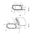
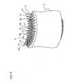
- FIG. 1 shows a structure of a formed coil type of a first embodiment of the present invention.
- FIG. 1A is an oblique view prior to fitting of a formed coil 5 to a stator core 2, and the stator core 2 is shown notched.
- FIG. 1B is an oblique view showing a state in which the formed coil 5 is fitted to the stator core 2, and the outline of the stator core 2 is shown in a two-dot broken line.
- a coil wire 1 is a square wire made of copper and covered with a thin film of enamel resin.
- the stator core 2 is made of a rolled plate of approximately 1 mm in thickness which is punched out and laminated.
- the coil wire 1 of the square wire of the same size or nearly the same size in length of two sides is continuously wound (three turns in FIG. 3), and a crown 12 which is an edgewise surface of the coil wire 1 double-wound and a coil terminal portion side crown 13 are bent and shaped in a crank shape so as to form a formed coil 5.
- the formed coil 5 is inserted into the stator slot 3 from the inside of the stator core 2.
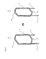
- FIG. 2 is shown a view of a state in which the formed coil 5 of the first embodiment of the present invention is fitted to the stator core 2.
- the rotary electric machine of the present invention comprises a total of 72 pieces of the formed coil 5 consisting of three phase coils of a U phase, a V phase, and a W phase with each phase in 24 pieces, and the corresponding stator core 2 having 72 pieces of the slot.
- FIG. 2A shows a top plan view of a distribution winding stator 8 seen from the crown 12 side in a state in which the formed coil 5 is fitted to the stator core 2.
- the formed coil 5 is not restricted to the insertion position of the slot, but has the same form for all the slots.
- the crown 12 is in the shape of a crank so that all the formed coils 5 can be fitted to the slots.
- the end portion of the coil wire 1 is connected to the end portion of the coil wire 1 of the same phase by welding so that a three phase coil of the U phase, the V phase, and the W phase is formed, thereby obtaining the distribution winding stator 8.
- FIG. 2B shows an enlarged cross-section of a portion of the stator slot 3 in a state in which the formed coil 5 is fitted to the stator core 2.
- the coil wire 1 is a square wire, and is configured to be disposed with two pairs of three turns of the square wires in the axial direction inside the stator slot 3 of the stator core 2, and disposed with six pieces of the conductors of the square wires in the axial direction inside one slot.
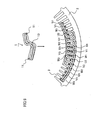
- FIG. 3 shows a step of a continuous winding of the square wire 1 by a coil winding machine.
- FIG. 3A shows an oblique view in a state in which the square wire 1 is set to a bobbin 30.
- FIG. 3B shows an oblique view in a state in which the square wire 1 is wound around the bobbin 30.
- FIG. 3C shows an oblique view of the winding coil 4 taken out from the bobbin 30.
- the square wire 1 is set to the bobbin 30 having a taper 31 given the predetermined tape angle.
- the bobbin 30 is rotated while giving a tensile force to the square wire 1, and the square wire 1 is wound around the bobbin 30, and when wound for the predetermined number of turns (three turns in the present invention), the square wire 1 continuously wound is taken out from the bobbin 30, and a winding coil 4 transferred with the taper angle of the taper 31 of the bobbin as shown in FIG. 3C is obtained.
- the taper angle required by the formed coil 5 is shaped at the stage of the winding coil 4.
- the number of slots of the stator core of the present invention is 72 pieces, and the slot into which one piece of the formed coil enters extends over seven pieces.
- the angle by which the formed coil enters inside the slot was taken as 7/72 of 360 degrees to 35 degrees. Consequently, the taper angle of the taper 31 of the bobbin 30 was taken as 17.5 degrees which are half the angle determined as described above.
- the tensile stress is loaded on the wire of the core outer peripheral side of the formed coil, and a compression stress on the wire of the core inner peripheral side.
- a compression stress is loaded on the wire, a buckling distortion is generated in order to alleviate this stress, thereby raising concern about the size of the formed coil becoming large.
- the tensile stress is always loaded on the wire, and therefore, depending on a long period of the driving circumstances of the rotary electric machine, the wire is at a risk of being broken.
- the range of the taper angle of the taper 31 in the first embodiment of the present invention is preferably 15 degrees to 20 degrees.
- FIG. 4 is a comparison view of rough shapes of the wiring coil 4 and the formed coil 5 formed in the form to be inserted into the slot of the stator.
- the formed coil 5, as shown in FIG. 2A, is shaped in the form to be fitted to the stator core 2. For this reason, it is necessary that the crown 12 and the terminal portion side crown 13 are bent in a crank shape in the edgewise surface of the coil wire 1 so as to shape the formed coil 5.
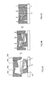
- FIG. 5 is a top plan view of a mold showing a deformation process from the winding coil 4 to the formed coil 5 and the winding coil 4 or the formed coil 5 seen from the crown 12 side.
- FIG. 5A shows a state in which the winding coil 4 is set to a bottom mold 32
- FIG. 5B a state in which side molds 33a and 33b and upper molds 34a and 34b are halfway through coming down
- FIG. 5C a state in which the side molds 33a and 33b, and the upper molds 34a and 34b have come down to the predetermined positions.
- the bottom mold 32, the side molds 33a and 33b, and the upper molds 34a and 34b are made of steel, and are hard molds increased in hardness by thermal refining, and to prevent an injury of the enamel coated layer by shaping, a mirror finishing is given to the surfaces contacted by the coil wire 1.
- FIGS. 5A to 5C after setting the wiring coil 4 to the bottom mold 32, the side molds 33a and 33b and the upper molds 34a and 34b are allowed to come down up to the predetermined positions, thereby shaping the formed coil 5.
- FIG. 6 shows an oblique view of a state in which the formed coil 5 is fitted into the stator slot of the stator core 2.
- the case is shown, in which the number of formed coils 5 is nine pieces.
- the reason why the straight portion is covered by the insulating sheet 6 is because both purposes of taking an insulating measure for the possible existence of pin holes in the enamel coated layer of the coil wire 1 and preventing an injury of the enamel coated layer at the fitting time into the stator core are to be met.
- the formed coil 5 attached with the insulating sheet 6 is inserted into the stator slot in sequence from the inner side of the stator core 2.
- FIG. 7 is a top plan view of the formed coil 5 seen from the crown 12 in a state of being fitted into the stator slot 3 of the stator core 2.
- the rotary electric machine of the present invention is of a three phase coil, and comprises coils of a U phase, a V phase and a W phase. Reference symbols of U, V, and W described in the figure show the U phase, the V phase, and the W phase, respectively, and subsequent figures show the number of the formed coil 5 allotted to the each phase.
- the formed coil 5 of the same shape is disposed in sequence of U1, V1, W1, U2, V2, W2, ..., and is fitted into the stator core 2.
- the actual number of formed coils 5 in the present invention is 24 pieces for each phase and a total of 72 pieces, and as shown in FIG. 2A, 72 pieces of the formed coil 5 are fitted into the stator core 2.
- FIG. 8 is a top plan view of three pieces of the formed coil 5 seen from the crown 12 in a state of being fitted into the stator slot 3 of the stator core 2.
- the place inside the stator slot 3 of the centermost formed coil 5 only is shown by a cross section.
- the stator core 2 is shown by a two-dot broken line.
- the crown 12 is allowed to be shifted by the width size B1 of the formed coil 5, and is formed in a crank shape within the range of the interval B2 of the adjacent stator slots 3. As a result, fitting the formed coil 5 of the same shape into each stator slot 3 of the stator core 2 is realized.
- the formed coil 5 When the formed coil 5 is formed by shifting larger than the width size B1, the whole size B3 of the formed coil 5 becomes large, so that the formed coil 5 does not enter the predetermined stator slot 3. Further, when the formed coil 5 is formed by shifting smaller than the width size B1, the whole size B3 of the formed coil 5 becomes small, so that the formed coil 5 does not enter the predetermined stator slot 3 likewise.
- the crown 12 of the formed coil 5 is formed in a crank shape outside the range of the interval B2 of the stator slot 3, a plurality of formed coils 5 abuts against each other and does not enter the stator slot 3.
- FIG. 9 shows a top plan view of the formed coil 5 seen from the terminal portion side crown 13 side in a state of being fitted into the stator slot 3 of the stator core 2.
- the case is shown, in which the number of formed coils 5 is nine pieces.
- Reference symbols of the formed coils 5 allotted in FIG. 7 to each phase of the U phase, the V phase, and the W phase are shown in the terminal portions 11.
- the terminal portions 11 are disposed such that U1 and U3 are adjacent to each other within the same stator slot, and further, within the adjacent stator slot, V1 and V3 are adjacent to each other, and further, within the adjacent stator slot, W1 and W3 are adjacent to each other. In this manner, within the same slot, the formed coils 5 of the same phase are formed to be fitted.
- FIG. 10 shows an oblique view of a state in which the formed coil 5 is fitted into the stator core 2 and is connected to the terminal portion 11.
- the case is shown, in which the number of formed coils 5 is nine pieces.
- reference symbols of the formed coils 5 allotted in FIG. 7 to each phase of the U phase, the V phase, and the W phase are shown in the terminal portions 11.
- the U1 and the U3 of the terminal portion 11 are connected by welding, so that the continuous U phase coil is formed.
- the V1 and the V3 are also connected by welding, so that the continuous V phase coil is formed.
- the W1 and the W3 are also connected by welding, so that the continuous W phase coil is formed.
- FIG. 11 shows a top plan view of a state in which the formed coil 5 is fitted into the stator core 2 and is connected to the terminal portion 11 seen from the terminal portion side 11.
- the U phase only is described with the number of the formed coil 5 allotted from 1 to 24. Further, the V phase and the W phase are described with the number of the formed coil 5 allotted from 1 to 23.
- the U1 and the U3 of the terminal portion 11 are connected by welding, so that the coil of the continuous U phase is formed.
- the U1 and the U3 of the terminal portion 11 are connected by welding, and subsequently, going around the U2 and the U4, the U3 and the U5 in subsequence up to the U23 and the U1, and the U24 and the U2, all the coils are connected by welding, thereby forming the continuous U phase coil.
- the V phase and the W phase go around the likewise, and are connected by welding.
- the U23 of the terminal portion 11 is connected with copper lead wires 7 by welding.
- the V23 and the W23 are likewise connected with the lead wires 7 by welding, and the distribution winding stator 8 in which the U phase, the V phase, and the W phase are connected to the lead wires 7 respectively is obtained.
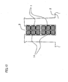
- FIG. 12 shows a cross-sectional view of a portion of the stator slot 3 in a state in which a formed coil is formed by a square wire 1 coated with a fusion bond 14 of a second embodiment of the present invention and is fitted into a stator core 2.
- Two pieces of the square wire 1 are adhered to roughly make one piece of the square wire, thereby forming a formed coil.
- the fusion bond 14 is fused by heating at the predetermined temperature.
- Two pieces of the square wire 1 are overlapped and given heating and cooling, so that they can be adhered to each other. This achieves a structure in which 12 pieces of the square wire 1 are disposed within one slot. As a result, the flux density is further increased and the current density is reduced, thereby increasing efficiency as the rotary electric machine.
Landscapes
- Engineering & Computer Science (AREA)
- Manufacturing & Machinery (AREA)
- Power Engineering (AREA)
- Windings For Motors And Generators (AREA)
- Manufacture Of Motors, Generators (AREA)
- Insulation, Fastening Of Motor, Generator Windings (AREA)
Abstract
Description
- The present invention relates to a rotary electric machine such as a motor and an electric generator, a crank-shaped continuously winding coil, a distribution winding stator and the forming method thereof.
- A form of a coil winding of a stator includes a concentrated winding to concentratedly wind a coil on each pole cog and a distribution winding to wind a coil by striding across a plurality of slots with hetero-phase coils or in-phase coils mutually overlapped at a coil end. The stator of the concentrated winding can make the coil end small, and is effective for miniaturization and high efficiency of the rotary electric machine. On the other hand, the stator of the distribution winding can cause a rotating magnetic field of the inner periphery of the stator to be closer to a sine wave, and has an output higher than the concentrated winding, and can reduce a noise. Further, in common with both windings, there is a method in which, as one of the means of achieving a high power output, a wire of rectangular cross section is used for the copper wire of the coil, thereby increasing a coil space factor inside the stator slot. The present invention targets at the rotary electric machine of the distribution winding in which the stator coil comprises the rectangular cross section wiring.
-
Japanese Patent Laid-Open Publication No. 4-168955 - Further,
Japanese Patent Laid-Open Publication No. 6-284651 - Further,
Japanese Patent Laid-Open Publication No. 8-298756 - Further,
Japanese Patent Laid-Open Publication No. 10-66314 - In these Prior Arts, in the distribution winding stator, the stator using the flat type rectangular conductor has the conductors disposed in a small division number in the radial direction inside the stator slot, and the stator using the rectangular conductors having the same or nearly the same vertical and horizontal size has a structure in which the crown of the conductor forming the coil end is protruded.
- The problems to be solved by the present invention is to invent the form of a coil and its forming method to obtain a rotary electric machine having a high power output in a distribution winding stator and aiming at miniaturization and high efficiency.
- With respect to the high power output, since the output of the rotary machine is approximately decided by the number of slots of the stator core and the shape thereof as well as the occupied area of the conductor occupying the inside of the slot, the increase in the space factor of the conductor inside the slot is the problem to be solved by the present invention.
- With respect to the miniaturization, since the size of the stator core is fixed, making the coil ends of the stator core both ends small to meet the size of the distribution winding stator is the problem for the miniaturization of the rotary electric machine. The conductor disclosed in
Japanese Patent Laid-Open Publication No. 6-284651 Japanese Patent Laid-Open Publication No. 8-298756 - With respect to the high efficiency, the reduction in the current density and the reduction in the copper loss can be cited. The conductor disclosed in
Japanese Patent Laid-Open Publication No. 4-168955 - Further, the conductor disclosed in
Japanese Patent Laid-Open Publication No. 6-284651 - The form of a coil and its formation method to solve the above described three problems are of importance, and an object of the present invention is to obtain the form of the coil and its formation method to obtain a rotary electric machine having a high power output and aiming at miniaturization and high efficiency in the distribution winding stator.
- The feature of the rotary electric machine of the present invention is such that the winding coil is formed with a crank-shaped portion without being accompanied with twisting on rough crown portions of both ends in the rotary electric machine comprising a multiple stator winding configured by storing inside a slot of the stator core a winding coil wound with a rectangular conductive wire having an insulating coated layer for plural times and formed into a coil shape.
- By the present invention, the distribution winding stator using the coil which winds a conductor of the rectangular cross section by a lap winding is structured such that the coil end is made smaller than before, and the conductor is split and disposed in the radial direction inside the slot. As a result, by bringing the advantages of the distribution winding stator excellent in rotary characteristics into play, the miniaturization and high efficiency of a rotary electric machine of a high power output can be realized.
-
- FIG. 1 is an explanatory drawing of a formed coil of a first embodiment of the present invention;
- FIG. 2 is an explanatory drawing of a distribution winding stator of the first embodiment of the present invention;
- FIG. 3 is an explanatory drawing of a continuously winding step in the formation process of the formed coil of the first embodiment of the present invention;
- FIG. 4 is an oblique view of a winding coil and the formed coil in the formation process of the first embodiment of the present invention;
- FIG. 5 is an explanatory drawing of the deformation process to shape from the winding coil to the formed coil of the first embodiment of the present invention;
- FIG. 6 is an oblique view of a state in which the formed coil being the first embodiment of the present invention is fitted into a stator slot;
- FIG. 7 is an oblique view of a state in which the formed coil being the first embodiment of the present invention is fitted into a stator slot;
- FIG. 8 is an explanatory drawing of the shape of the formed coil fitted into the stator slot being the first embodiment of the present embodiment;
- FIG. 9 is a top plan view of the formed coil being the first embodiment of the present invention seen from a terminal portion side in a state of being fitted inside the stator slot;
- FIG. 10 is an oblique view of a state in which the formed coil being the first embodiment of the present invention is fitted to the stator and connected to the terminal portion;
- FIG. 11 is a top plan view of the distribution winding stator being the first embodiment of the present invention seen from the terminal portion side; and
- FIG. 12 is a cross-sectional view inside the slot of the distribution winding stator being a second embodiment of the present invention.
- Embodiments of the present invention will be described below by using the drawings.
- FIG. 1 shows a structure of a formed coil type of a first embodiment of the present invention. FIG. 1A is an oblique view prior to fitting of a formed
coil 5 to astator core 2, and thestator core 2 is shown notched. FIG. 1B is an oblique view showing a state in which theformed coil 5 is fitted to thestator core 2, and the outline of thestator core 2 is shown in a two-dot broken line. Acoil wire 1 is a square wire made of copper and covered with a thin film of enamel resin. Thestator core 2 is made of a rolled plate of approximately 1 mm in thickness which is punched out and laminated. Thecoil wire 1 of the square wire of the same size or nearly the same size in length of two sides is continuously wound (three turns in FIG. 3), and acrown 12 which is an edgewise surface of thecoil wire 1 double-wound and a coil terminalportion side crown 13 are bent and shaped in a crank shape so as to form a formedcoil 5. Theformed coil 5 is inserted into thestator slot 3 from the inside of thestator core 2. - In FIG. 2 is shown a view of a state in which the formed
coil 5 of the first embodiment of the present invention is fitted to thestator core 2. The rotary electric machine of the present invention comprises a total of 72 pieces of the formedcoil 5 consisting of three phase coils of a U phase, a V phase, and a W phase with each phase in 24 pieces, and thecorresponding stator core 2 having 72 pieces of the slot. FIG. 2A shows a top plan view of adistribution winding stator 8 seen from thecrown 12 side in a state in which the formedcoil 5 is fitted to thestator core 2. Theformed coil 5 is not restricted to the insertion position of the slot, but has the same form for all the slots. Thecrown 12 is in the shape of a crank so that all the formed coils 5 can be fitted to the slots. Although a description will be made in the explanation of FIGS. 10 and 11, the end portion of thecoil wire 1 is connected to the end portion of thecoil wire 1 of the same phase by welding so that a three phase coil of the U phase, the V phase, and the W phase is formed, thereby obtaining thedistribution winding stator 8. - FIG. 2B shows an enlarged cross-section of a portion of the
stator slot 3 in a state in which the formedcoil 5 is fitted to thestator core 2. If a total cross-section area of thecoil wire 1 inside thestator slot 3 is the same, the greater the number of wirings is, the higher the flux density is. In the present invention, thecoil wire 1 is a square wire, and is configured to be disposed with two pairs of three turns of the square wires in the axial direction inside thestator slot 3 of thestator core 2, and disposed with six pieces of the conductors of the square wires in the axial direction inside one slot. As a result, rather than two pieces of the flat square wire conductors being disposed in the axial direction inside one slot, six pieces of the square wire conductors being disposed makes the flux density higher, so that the current density is reduced and the efficiency as the rotary electric machine is improved. - The shaping method of the formed coil of the present invention will be described by using FIGS. 3 to 5.
- FIG. 3 shows a step of a continuous winding of the
square wire 1 by a coil winding machine. FIG. 3A shows an oblique view in a state in which thesquare wire 1 is set to abobbin 30. FIG. 3B shows an oblique view in a state in which thesquare wire 1 is wound around thebobbin 30. FIG. 3C shows an oblique view of the windingcoil 4 taken out from thebobbin 30. - First, as shown in FIG. 3A, the
square wire 1 is set to thebobbin 30 having ataper 31 given the predetermined tape angle. Next, as shown in FIG. 3B, thebobbin 30 is rotated while giving a tensile force to thesquare wire 1, and thesquare wire 1 is wound around thebobbin 30, and when wound for the predetermined number of turns (three turns in the present invention), thesquare wire 1 continuously wound is taken out from thebobbin 30, and a windingcoil 4 transferred with the taper angle of thetaper 31 of the bobbin as shown in FIG. 3C is obtained. - In the present invention, the taper angle required by the formed
coil 5 is shaped at the stage of the windingcoil 4. The number of slots of the stator core of the present invention is 72 pieces, and the slot into which one piece of the formed coil enters extends over seven pieces. As a result, the angle by which the formed coil enters inside the slot was taken as 7/72 of 360 degrees to 35 degrees. Consequently, the taper angle of thetaper 31 of thebobbin 30 was taken as 17.5 degrees which are half the angle determined as described above. When the taper angle is large, a compression stress is loaded on the wire at the core outer peripheral side of the formed coil, and a tensile stress on the wire at the core inner peripheral side. Further, when the taper angle is small, the tensile stress is loaded on the wire of the core outer peripheral side of the formed coil, and a compression stress on the wire of the core inner peripheral side. When a compression stress is loaded on the wire, a buckling distortion is generated in order to alleviate this stress, thereby raising concern about the size of the formed coil becoming large. On the other hand, when a tensile stress is loaded on the wire, since there is no stress release due to deformation, the tensile stress is always loaded on the wire, and therefore, depending on a long period of the driving circumstances of the rotary electric machine, the wire is at a risk of being broken. The range of the taper angle of thetaper 31 in the first embodiment of the present invention is preferably 15 degrees to 20 degrees. - FIG. 4 is a comparison view of rough shapes of the
wiring coil 4 and the formedcoil 5 formed in the form to be inserted into the slot of the stator. The formedcoil 5, as shown in FIG. 2A, is shaped in the form to be fitted to thestator core 2. For this reason, it is necessary that thecrown 12 and the terminalportion side crown 13 are bent in a crank shape in the edgewise surface of thecoil wire 1 so as to shape the formedcoil 5. - FIG. 5 is a top plan view of a mold showing a deformation process from the winding
coil 4 to the formedcoil 5 and the windingcoil 4 or the formedcoil 5 seen from thecrown 12 side. FIG. 5A shows a state in which the windingcoil 4 is set to abottom mold 32, FIG. 5B a state in whichside molds upper molds side molds upper molds - The
bottom mold 32, theside molds upper molds coil wire 1. As shown in FIGS. 5A to 5C, after setting thewiring coil 4 to thebottom mold 32, theside molds upper molds coil 5. - FIG. 6 shows an oblique view of a state in which the formed
coil 5 is fitted into the stator slot of thestator core 2. For ease of explanation, the case is shown, in which the number of formedcoils 5 is nine pieces. First, the straight line portion of the formedcoil 5, which is equivalent to a position inserted inside the stator slot of thestator core 2, is covered with an insulating sheet 6. The reason why the straight portion is covered by the insulating sheet 6 is because both purposes of taking an insulating measure for the possible existence of pin holes in the enamel coated layer of thecoil wire 1 and preventing an injury of the enamel coated layer at the fitting time into the stator core are to be met. - Next, the formed
coil 5 attached with the insulating sheet 6 is inserted into the stator slot in sequence from the inner side of thestator core 2. - FIG. 7 is a top plan view of the formed
coil 5 seen from thecrown 12 in a state of being fitted into thestator slot 3 of thestator core 2. For ease of explanation, the case is shown, in which the number of formedcoils 5 is nine pieces. The rotary electric machine of the present invention is of a three phase coil, and comprises coils of a U phase, a V phase and a W phase. Reference symbols of U, V, and W described in the figure show the U phase, the V phase, and the W phase, respectively, and subsequent figures show the number of the formedcoil 5 allotted to the each phase. The formedcoil 5 of the same shape is disposed in sequence of U1, V1, W1, U2, V2, W2, ..., and is fitted into thestator core 2. The actual number of formedcoils 5 in the present invention is 24 pieces for each phase and a total of 72 pieces, and as shown in FIG. 2A, 72 pieces of the formedcoil 5 are fitted into thestator core 2. - FIG. 8 is a top plan view of three pieces of the formed
coil 5 seen from thecrown 12 in a state of being fitted into thestator slot 3 of thestator core 2. For ease of explanation, the place inside thestator slot 3 of the centermost formedcoil 5 only is shown by a cross section. Further, thestator core 2 is shown by a two-dot broken line. Thecrown 12 is allowed to be shifted by the width size B1 of the formedcoil 5, and is formed in a crank shape within the range of the interval B2 of theadjacent stator slots 3. As a result, fitting the formedcoil 5 of the same shape into eachstator slot 3 of thestator core 2 is realized. - When the formed
coil 5 is formed by shifting larger than the width size B1, the whole size B3 of the formedcoil 5 becomes large, so that the formedcoil 5 does not enter thepredetermined stator slot 3. Further, when the formedcoil 5 is formed by shifting smaller than the width size B1, the whole size B3 of the formedcoil 5 becomes small, so that the formedcoil 5 does not enter thepredetermined stator slot 3 likewise. On the other hand, when thecrown 12 of the formedcoil 5 is formed in a crank shape outside the range of the interval B2 of thestator slot 3, a plurality of formedcoils 5 abuts against each other and does not enter thestator slot 3. - FIG. 9 shows a top plan view of the formed
coil 5 seen from the terminalportion side crown 13 side in a state of being fitted into thestator slot 3 of thestator core 2. For ease of explanation, the case is shown, in which the number of formedcoils 5 is nine pieces. Reference symbols of the formed coils 5 allotted in FIG. 7 to each phase of the U phase, the V phase, and the W phase are shown in theterminal portions 11. Theterminal portions 11 are disposed such that U1 and U3 are adjacent to each other within the same stator slot, and further, within the adjacent stator slot, V1 and V3 are adjacent to each other, and further, within the adjacent stator slot, W1 and W3 are adjacent to each other. In this manner, within the same slot, the formed coils 5 of the same phase are formed to be fitted. - FIG. 10 shows an oblique view of a state in which the formed
coil 5 is fitted into thestator core 2 and is connected to theterminal portion 11. For ease of explanation, the case is shown, in which the number of formedcoils 5 is nine pieces. Further, reference symbols of the formed coils 5 allotted in FIG. 7 to each phase of the U phase, the V phase, and the W phase are shown in theterminal portions 11. The U1 and the U3 of theterminal portion 11 are connected by welding, so that the continuous U phase coil is formed. Further, the V1 and the V3 are also connected by welding, so that the continuous V phase coil is formed. Further, the W1 and the W3 are also connected by welding, so that the continuous W phase coil is formed. - FIG. 11 shows a top plan view of a state in which the formed
coil 5 is fitted into thestator core 2 and is connected to theterminal portion 11 seen from theterminal portion side 11. The U phase only is described with the number of the formedcoil 5 allotted from 1 to 24. Further, the V phase and the W phase are described with the number of the formedcoil 5 allotted from 1 to 23. The U1 and the U3 of theterminal portion 11 are connected by welding, so that the coil of the continuous U phase is formed. - The U1 and the U3 of the
terminal portion 11 are connected by welding, and subsequently, going around the U2 and the U4, the U3 and the U5 in subsequence up to the U23 and the U1, and the U24 and the U2, all the coils are connected by welding, thereby forming the continuous U phase coil. Although not illustrated, the V phase and the W phase go around the likewise, and are connected by welding. Further, the U23 of theterminal portion 11 is connected withcopper lead wires 7 by welding. Further, the V23 and the W23 are likewise connected with thelead wires 7 by welding, and thedistribution winding stator 8 in which the U phase, the V phase, and the W phase are connected to thelead wires 7 respectively is obtained. - FIG. 12 shows a cross-sectional view of a portion of the
stator slot 3 in a state in which a formed coil is formed by asquare wire 1 coated with afusion bond 14 of a second embodiment of the present invention and is fitted into astator core 2. Two pieces of thesquare wire 1 are adhered to roughly make one piece of the square wire, thereby forming a formed coil. Thefusion bond 14 is fused by heating at the predetermined temperature. Two pieces of thesquare wire 1 are overlapped and given heating and cooling, so that they can be adhered to each other. This achieves a structure in which 12 pieces of thesquare wire 1 are disposed within one slot. As a result, the flux density is further increased and the current density is reduced, thereby increasing efficiency as the rotary electric machine.
Claims (8)
- A rotary electric machine comprising a multiple stator winding having, inside a slot of the stator, a winding coil (5) having plural windings of a rectangular conductive wire (1) having an insulating coating and formed into a coil shape, wherein the winding coil is formed with a crank-shaped portion (12, 13) on both ends without being accompanied by twisting.
- The rotary electric machine of claim 1, wherein the crank shape portion of the winding coil is formed on the edgewise surface of the rectangular conductive wire forming the winding coil having plural windings.
- The rotary electric machine of claim 1 or 2, wherein the crank shape portion of the winding coil is formed by shifting a width size in the line-up direction of the rectangular conductive wire forming the winding coil.
- The rotary electric machine of any of claims 1 to 3, wherein the crank shape portion of the winding coil is formed in a range smaller than the intervals of adjacent slots (3) formed in the stator.
- A crank-shaped continuous winding coil, wherein a conductive wire (1) having a rectangular cross-section and an insulating coating is wound plural times by superposing both side surfaces of the conductive wire corresponding to the rectangular cross-section, and broad surfaces having a width size corresponding to plural of the conductive wires are formed perpendicular to the superposed side surfaces, comprising:the winding coil (5) with parts of its broad surface formed in parallel with each other;terminal portions (11) on both ends of the winding coil, each extending on a straight line in the same direction as the broad surfaces on both sides of the winding coil; anda crank shape formed by a displacement by the width size of the broad surface along the broad surface roughly on crowns (12, 13) on both ends of the winding coil without being accompanied by twisting, so that the terminal portions on both ends are disposed to approach the width direction by the displacement.
- A method of forming a crank-shaped continuous winding coil (5), comprising the steps of:forming a winding coil (5) by winding plural times a conductive wire (1) having a rectangular cross section and an insulating coating;extending terminal portions (11) on both ends of the winding coil; andforming a crank shaped portion on a pair of crowns (12, 13) of the winding coil,wherein, in the step of forming the winding coil, both side surfaces of the conductive wire corresponding to the rectangular cross section are superposed and wound plural times, and broad surfaces corresponding to plural of the conductive wires are formed perpendicular to the superposed side surfaces, and the winding coil is formed so that parts of the broad surfaces face each other and are formed in parallel,
wherein, in the step of extending the terminal portions, the terminal portions on both ends are each extended on a straight line in the same direction as the parallel broad surfaces formed on both sides of the winding coil, at an interval in the width direction of the broad surface, and
wherein, in the step of forming the crank shape portion, a crank shape with a displacement by the width of the broad surface is formed along the broad surface roughly on crowns (12, 13) on both ends of the winding coil without being accompanied by twisting, and the terminal portions on both ends are configured to approach the width direction of the broad surface. - A distributed winding stator of a rotary electric machine, wherein a conductive wire (1) having a rectangular cross-section and an insulating coating is wound plural times by superposing both side surfaces of the conductive wire corresponding to the rectangular cross section, and broad surfaces having a width size corresponding to plural of the conductive wires are formed perpendicular to the superposed side surfaces, comprising:a winding coil (5) with parts of its broad surface formed in parallel with each other;terminal portions (11) on both ends of the winding coil, each extending on a straight line in the same direction as the broad surfaces at both sides of the winding coil; anda crank shape formed by a displacement by the width size of the broad surface along the broad surface roughly on crowns (12, 13) on both ends of the winding coil without being accompanied by twisting,wherein the continuous winding coils having the crank shape, where the terminal portions on the both ends are disposed to approach the width direction by the displacement in the crank shape, are inserted into a plurality of stator slots (3) of the stator core of the rotary electric machine, the crank shape of the continuous winding coil is disposed by striding over the stator slots, and at the same time, one of the broad surfaces formed in parallel by displacement by the width of the broad surface along the broad surface is disposed at the innermost side of the stator slot, and the other of the broad surfaces formed in parallel is disposed at the entry side of the stator slot, and the terminal portions of different winding coils inserted into different stator slots are disposed close to a center portion between the innermost side and the entry side of the stator slot and are electrically connected.
- A method of forming a distributed winding stator of a rotary electric machine, wherein a conductive wire (1) having a rectangular cross-section and an insulating coating is wound plural times by superposing both side surfaces of the conductive wire corresponding to the rectangular cross section, and broad surfaces having a width size corresponding to plural of the conductive wires are formed perpendicular to the superposed side surfaces, comprising:a winding coil (5) with parts of its broad surface formed in parallel with each other;terminal portions (11) on both ends of the winding coil, each extending on a straight line in the same direction as the broad surfaces on both sides of the winding coil; anda crank shape formed by a displacement by the width size of the broad surface along the broad surface roughly on crowns (12, 13) on both ends of the winding coil without being accompanied by twisting,wherein the crank shape is formed by a displacement by the width size of the broad surface along the broad surface without being accompanied by twisting, thereby providing a step of inserting the continuous winding coil having the crank shape, with the terminal portions on both ends disposed so as to approach the width direction by the displacement in the crank shape, into a plurality of stator slots (3) from the inner side of the stator core, and a step of disposing the crank shape of the continuous winding coil by striding over the stator slots, and at the same time, disposing one of the broad surfaces formed in parallel by the displacement by the width of the broad surface along the broad surface at the innermost side of the stator slot, and disposing the other of the broad surfaces formed in parallel at the entry side of the stator slot, and
disposing the terminal portions of different winding coils inserted into different stator slots close to the center portion between the innermost side and the entry side of the stator slot and electrically connecting them by welding.
Applications Claiming Priority (1)
| Application Number | Priority Date | Filing Date | Title |
|---|---|---|---|
| JP2006284780A JP4234749B2 (en) | 2006-10-19 | 2006-10-19 | Rotating electric machine, crank-shaped continuous winding coil, distributed winding stator and method for forming them |
Publications (2)
| Publication Number | Publication Date |
|---|---|
| EP1914866A2 true EP1914866A2 (en) | 2008-04-23 |
| EP1914866A3 EP1914866A3 (en) | 2016-04-06 |
Family
ID=38982419
Family Applications (1)
| Application Number | Title | Priority Date | Filing Date |
|---|---|---|---|
| EP07020509.1A Withdrawn EP1914866A3 (en) | 2006-10-19 | 2007-10-19 | Stator winding and forming method thereof |
Country Status (3)
| Country | Link |
|---|---|
| US (1) | US7825562B2 (en) |
| EP (1) | EP1914866A3 (en) |
| JP (1) | JP4234749B2 (en) |
Cited By (11)
| Publication number | Priority date | Publication date | Assignee | Title |
|---|---|---|---|---|
| WO2009142097A1 (en) | 2008-05-21 | 2009-11-26 | Toyota Jidosha Kabushiki Kaisha | Winding method, winding apparatus, and stator |
| CN102668332A (en) * | 2010-06-11 | 2012-09-12 | 丰田自动车株式会社 | Stator and method for manufacturing unit coil used for same |
| US20140091665A1 (en) * | 2009-01-15 | 2014-04-03 | Valeo Equipements Electriques Moteur | Electric rotating machine, mainly for starter of automotive vehicle |
| US9287744B2 (en) | 2010-09-21 | 2016-03-15 | Nissan Motor Co., Ltd. | Winding structure, rotating electric machine, and rotating electric machine manufacturing method |
| CN106160371A (en) * | 2016-07-12 | 2016-11-23 | 中车株洲电机有限公司 | A kind of motor stator entirety rule forming method |
| WO2016189192A1 (en) * | 2015-05-27 | 2016-12-01 | Lappeenrannan Teknillinen Yliopisto | A winding of an electric machine |
| CN106575895A (en) * | 2014-09-19 | 2017-04-19 | 三菱电机株式会社 | Stator, rotating electric machine using same, manufacturing method of stator, and manufacturing method of rotating electric machine |
| EP3145058A4 (en) * | 2014-09-01 | 2017-10-18 | Aisin Aw Co., Ltd. | Stator assembling method and stator |
| CN109904963A (en) * | 2019-05-05 | 2019-06-18 | 合肥巨一动力系统有限公司 | A kind of flat wire motor stator |
| CN110571962A (en) * | 2019-09-16 | 2019-12-13 | 合肥巨一动力系统有限公司 | A flat wire motor stator |
| US10605230B1 (en) | 2017-02-16 | 2020-03-31 | Stuart Lahtinen | Wind turbine assembly |
Families Citing this family (69)
| Publication number | Priority date | Publication date | Assignee | Title |
|---|---|---|---|---|
| JP2009077468A (en) | 2007-09-19 | 2009-04-09 | Hitachi Ltd | Rotating electric machine and method of manufacturing rotating electric machine |
| JP5177512B2 (en) * | 2008-04-07 | 2013-04-03 | 株式会社デンソー | Assembly method of split core type stator of inner rotor type rotating electrical machine |
| JP5332347B2 (en) * | 2008-06-30 | 2013-11-06 | 株式会社デンソー | Coil wire rod for coil assembly of rotating electrical machine |
| US8040007B2 (en) | 2008-07-28 | 2011-10-18 | Direct Drive Systems, Inc. | Rotor for electric machine having a sleeve with segmented layers |
| JP5131561B2 (en) | 2009-03-13 | 2013-01-30 | アイシン・エィ・ダブリュ株式会社 | Coil manufacturing method, coil manufacturing apparatus, and coil |
| JP5146778B2 (en) * | 2009-03-13 | 2013-02-20 | アイシン・エィ・ダブリュ株式会社 | Wire rod forming apparatus and coil manufacturing apparatus |
| US8258669B2 (en) * | 2009-05-21 | 2012-09-04 | Honda Motor Co., Ltd. | Motor with stator configuration for increased coil length and coil space factors |
| DE102009024231A1 (en) * | 2009-05-29 | 2010-12-09 | Robert Bosch Gmbh | Method for producing a stator winding of an electrical machine, in particular an AC generator |
| US20100277136A1 (en) * | 2009-09-29 | 2010-11-04 | American Superconductor Corporation | Generator with ferromagnetic teeth |
| JP5287674B2 (en) * | 2009-11-11 | 2013-09-11 | トヨタ自動車株式会社 | Stator manufacturing method and stator manufacturing apparatus |
| JP5278546B2 (en) * | 2009-12-18 | 2013-09-04 | トヨタ自動車株式会社 | Stator |
| DE112011100868T5 (en) | 2010-03-11 | 2012-12-27 | Kabushiki Kaisha Toyota Jidoshokki | Stator for a rotating electrical machine, method of manufacturing a stator and method of producing a winding for a stator |
| JP5563876B2 (en) * | 2010-04-20 | 2014-07-30 | 本田技研工業株式会社 | Coil manufacturing method and motor |
| US8487498B2 (en) | 2010-07-30 | 2013-07-16 | Hamilton Sundstrand Corporation | Multiple conductor winding in stator |
| JP5560176B2 (en) * | 2010-12-08 | 2014-07-23 | トヨタ自動車株式会社 | Motor and motor manufacturing method |
| JP5682307B2 (en) * | 2010-12-28 | 2015-03-11 | 株式会社デンソー | Stator for rotating electric machine and method for manufacturing the same |
| JP5702179B2 (en) * | 2011-02-09 | 2015-04-15 | 本田技研工業株式会社 | Coil segment manufacturing method |
| JP5516562B2 (en) * | 2011-02-09 | 2014-06-11 | 株式会社豊田自動織機 | Coil, stator and coil manufacturing method |
| JP5418686B2 (en) | 2011-04-05 | 2014-02-19 | トヨタ自動車株式会社 | Stator and stator manufacturing method |
| JP5674540B2 (en) | 2011-04-13 | 2015-02-25 | 日立オートモティブシステムズ株式会社 | Stator and rotating electric machine |
| EP2763295B1 (en) * | 2011-09-27 | 2017-10-25 | Toyota Jidosha Kabushiki Kaisha | Segmented-coil manufacturing method, segmented-coil manufacturing device, and segmented coil manufactured using the method and the device |
| JP5631345B2 (en) | 2012-02-28 | 2014-11-26 | アイシン・エィ・ダブリュ株式会社 | Coil manufacturing method |
| JP5674693B2 (en) * | 2012-03-01 | 2015-02-25 | アイシン・エィ・ダブリュ株式会社 | Winding forming apparatus and winding forming method |
| JP5603365B2 (en) * | 2012-03-22 | 2014-10-08 | 三菱電機株式会社 | Rotating electric machine |
| US9236784B2 (en) * | 2012-03-30 | 2016-01-12 | General Electric Company | Flux-switching electric machine |
| JP5860767B2 (en) * | 2012-05-31 | 2016-02-16 | アイシン・エィ・ダブリュ株式会社 | Coil manufacturing method |
| JP6033582B2 (en) | 2012-06-22 | 2016-11-30 | アイシン・エィ・ダブリュ株式会社 | Stator and stator manufacturing method |
| JP2014011937A (en) * | 2012-07-03 | 2014-01-20 | Aisin Aw Co Ltd | Stator |
| JP5789570B2 (en) * | 2012-07-03 | 2015-10-07 | アイシン・エィ・ダブリュ株式会社 | Stator |
| DE112013003398T5 (en) | 2012-07-06 | 2015-04-09 | Mitsubishi Electric Corporation | Rotating electrical machine and manufacturing process for this |
| US9712024B2 (en) | 2012-07-25 | 2017-07-18 | Aisin Aw Co., Ltd. | Coil end shaping apparatus and method |
| JP5838930B2 (en) * | 2012-08-08 | 2016-01-06 | 株式会社豊田自動織機 | Coil and stator |
| WO2014033715A1 (en) * | 2012-08-27 | 2014-03-06 | Albus Technologies Ltd. | Rotor with magnet pattern |
| US9641036B2 (en) | 2012-08-31 | 2017-05-02 | Mitsubishi Electric Corporation | Rotary electric machine |
| JP5924711B2 (en) * | 2012-10-22 | 2016-05-25 | 三菱電機株式会社 | Manufacturing method of winding body used for armature winding for electric machine |
| CN105191071B (en) * | 2013-02-18 | 2017-09-26 | 三菱电机株式会社 | rotating electrical machine |
| WO2014155630A1 (en) * | 2013-03-28 | 2014-10-02 | 三菱電機株式会社 | Rotating electrical machine |
| JP6070496B2 (en) * | 2013-03-29 | 2017-02-01 | アイシン・エィ・ダブリュ株式会社 | Stator coil winding forming apparatus and winding forming method |
| JP6146219B2 (en) * | 2013-03-29 | 2017-06-14 | アイシン・エィ・ダブリュ株式会社 | Concentric winding coil forming method and forming apparatus |
| JP5941015B2 (en) * | 2013-05-17 | 2016-06-29 | アイシン・エィ・ダブリュ株式会社 | Manufacturing method of stator for rotating electric machine |
| KR102129015B1 (en) * | 2013-07-24 | 2020-07-02 | 현대모비스 주식회사 | Manufacturing method of coil for motor |
| CN105432000B (en) * | 2013-08-26 | 2018-06-08 | 三菱电机株式会社 | rotating electrical machine |
| JP6206052B2 (en) * | 2013-09-30 | 2017-10-04 | アイシン・エィ・ダブリュ株式会社 | Concentric winding coil forming method and forming apparatus |
| JP6206051B2 (en) * | 2013-09-30 | 2017-10-04 | アイシン・エィ・ダブリュ株式会社 | Concentric winding coil forming method and forming apparatus |
| JP6165260B2 (en) * | 2013-10-08 | 2017-07-19 | 三菱電機株式会社 | Rotating electric machine |
| EP2874279A1 (en) * | 2013-11-15 | 2015-05-20 | Siemens Aktiengesellschaft | Method for producing a winding for a coil winding of a rotor of a rotating electric machine |
| WO2015111287A1 (en) * | 2014-01-23 | 2015-07-30 | 三菱電機株式会社 | Manufacturing method of stator winding coil |
| JP6135535B2 (en) * | 2014-02-07 | 2017-05-31 | 株式会社デンソー | Rotating electric machine stator |
| JP6206588B2 (en) | 2014-06-05 | 2017-10-04 | アイシン・エィ・ダブリュ株式会社 | Stator assembly method and stator assembly apparatus |
| CN106233593B (en) * | 2014-06-20 | 2019-01-15 | 三菱电机株式会社 | The manufacturing method of rotating electric machine |
| CN106663975B (en) * | 2014-08-07 | 2020-03-27 | 日立汽车系统株式会社 | Stator for rotating electrical machine, and rotating electrical machine provided with same |
| US20160254718A1 (en) * | 2015-02-26 | 2016-09-01 | Nidec Copal Corporation | Segment conductors, stator, rotating electrical machine, and vehicle and method of manufacturing the segment conductors |
| JP2016208745A (en) * | 2015-04-24 | 2016-12-08 | 株式会社安川電機 | Rotary electric machine, method for manufacturing rotary electric machine, stator coil, and coil resin structure |
| WO2017014217A1 (en) * | 2015-07-23 | 2017-01-26 | アイシン・エィ・ダブリュ株式会社 | Stator and method of manufacturing stator |
| WO2017038706A1 (en) * | 2015-08-28 | 2017-03-09 | アイシン・エィ・ダブリュ株式会社 | Stator coil, method for producing stator, and rotary electric machine |
| US10910930B2 (en) | 2015-10-26 | 2021-02-02 | Dana Tm4 Inc. | Machine for shaping rectangular wire coil heads |
| JP7210128B2 (en) * | 2017-02-10 | 2023-01-23 | 三菱電機株式会社 | Rotating electric machine, method for manufacturing tortoiseshell-shaped coil, and manufacturing apparatus for tortoiseshell-shaped coil |
| US10679789B2 (en) * | 2017-05-22 | 2020-06-09 | Selco Co., Ltd. | Method of manufacturing high-density coil |
| JP6430599B1 (en) * | 2017-08-04 | 2018-11-28 | 株式会社小田原エンジニアリング | Coil segment forming apparatus, coil segment forming method, and rotating electrical machine manufacturing apparatus |
| US11108307B2 (en) * | 2017-09-29 | 2021-08-31 | Honda Motor Co., Ltd. | Coil for rotary electric machine and insertion method |
| JP7094140B2 (en) * | 2018-05-21 | 2022-07-01 | 三菱電機株式会社 | Equipment for manufacturing unit coils for stators of rotary electric machines and methods for manufacturing unit coils |
| JP7019833B2 (en) * | 2018-10-12 | 2022-02-15 | 三菱電機株式会社 | A method for manufacturing a unit coil for a stator of a rotary electric machine, a device for manufacturing a unit coil for a stator of a rotary electric machine, and a method for manufacturing a rotary electric machine and a rotary electric machine. |
| WO2020202711A1 (en) * | 2019-03-29 | 2020-10-08 | 日本電産株式会社 | Stator, stator manufacturing method, and motor |
| JP6872289B1 (en) * | 2019-12-13 | 2021-05-19 | 三菱電機株式会社 | Rotating machine and its manufacturing method |
| KR102696292B1 (en) * | 2020-01-08 | 2024-08-20 | 엘지마그나 이파워트레인 주식회사 | Stator ofelectric rotation machine |
| JP7463740B2 (en) * | 2020-01-28 | 2024-04-09 | 株式会社デンソー | Rotating Electric Machine |
| JP2022151969A (en) * | 2021-03-29 | 2022-10-12 | 日本電産株式会社 | stator and motor |
| EP4362287A1 (en) * | 2022-10-25 | 2024-05-01 | Wilo Se | Electric motor for a borehole pump and related manufacturing method and tool |
| WO2025205332A1 (en) * | 2024-03-29 | 2025-10-02 | 株式会社アイシン | Stator |
Family Cites Families (16)
| Publication number | Priority date | Publication date | Assignee | Title |
|---|---|---|---|---|
| US3453468A (en) * | 1966-09-21 | 1969-07-01 | Kurz & Root Co Inc | Dynamoelectric machine winding arrangement with end turn insulation and method of making the same |
| CH559455A5 (en) * | 1973-06-12 | 1975-02-28 | Bbc Brown Boveri & Cie | |
| SE425586B (en) * | 1981-03-04 | 1982-10-11 | Asea Ab | SET TO MAKE A REVENUE FOR AN ELECTRIC MACHINE |
| JPS6218952A (en) * | 1985-07-15 | 1987-01-27 | Mitsubishi Electric Corp | Armature of ac generator for vehicle, and its manufacture |
| US4833356A (en) * | 1987-12-28 | 1989-05-23 | Sundstrand Corporation | Compact connections for interdispersed armature winding |
| JP2595129B2 (en) | 1990-10-31 | 1997-03-26 | 株式会社日立製作所 | Combination structure of armature coil and commutator segment of rotating electric machine |
| JPH06284651A (en) | 1993-12-27 | 1994-10-07 | Mitsubishi Electric Corp | Electric motor coil manufacturing method |
| US5714824A (en) | 1994-06-23 | 1998-02-03 | Hydro-Quebec | Conductor section for a stator frame of a polyphase dynamoelectric machine |
| JPH08298756A (en) | 1995-04-25 | 1996-11-12 | Toyota Motor Corp | Motor stator manufacturing method and stator core |
| JPH1066314A (en) | 1996-08-14 | 1998-03-06 | Toyota Motor Corp | Motor stator manufacturing method |
| US6313556B1 (en) * | 1999-09-30 | 2001-11-06 | Reliance Electric Technologies, Llc | Superconducting electromechanical rotating device having a liquid-cooled, potted, one layer stator winding |
| JP4403801B2 (en) * | 2001-07-31 | 2010-01-27 | アイシン・エィ・ダブリュ株式会社 | Motor manufacturing method and coil insertion device |
| JP2003143818A (en) | 2001-10-30 | 2003-05-16 | Toyota Motor Corp | Manufacturing method of split conductor of coil |
| JP3903922B2 (en) | 2003-01-27 | 2007-04-11 | 株式会社デンソー | Concentrated winding stator coil of rotating electric machine |
| WO2006113994A1 (en) * | 2005-04-26 | 2006-11-02 | Tm4 Inc. | Rectangular wire coil head shaping machine and method therefor |
| WO2008020471A1 (en) * | 2006-08-15 | 2008-02-21 | Hitachi, Ltd. | Rotating electric machine |
-
2006
- 2006-10-19 JP JP2006284780A patent/JP4234749B2/en active Active
-
2007
- 2007-10-18 US US11/874,291 patent/US7825562B2/en active Active
- 2007-10-19 EP EP07020509.1A patent/EP1914866A3/en not_active Withdrawn
Cited By (16)
| Publication number | Priority date | Publication date | Assignee | Title |
|---|---|---|---|---|
| US9748826B2 (en) | 2008-05-21 | 2017-08-29 | Toyota Jidosha Kabushiki Kaisha | Winding method, winding apparatus, and stator |
| CN102037527B (en) * | 2008-05-21 | 2013-02-13 | 丰田自动车株式会社 | Winding method, winding apparatus, and stator |
| WO2009142097A1 (en) | 2008-05-21 | 2009-11-26 | Toyota Jidosha Kabushiki Kaisha | Winding method, winding apparatus, and stator |
| US20140091665A1 (en) * | 2009-01-15 | 2014-04-03 | Valeo Equipements Electriques Moteur | Electric rotating machine, mainly for starter of automotive vehicle |
| CN102668332A (en) * | 2010-06-11 | 2012-09-12 | 丰田自动车株式会社 | Stator and method for manufacturing unit coil used for same |
| CN102668332B (en) * | 2010-06-11 | 2015-04-08 | 丰田自动车株式会社 | Stator and method for manufacturing unit coil used for same |
| US9287744B2 (en) | 2010-09-21 | 2016-03-15 | Nissan Motor Co., Ltd. | Winding structure, rotating electric machine, and rotating electric machine manufacturing method |
| US10594183B2 (en) | 2014-09-01 | 2020-03-17 | Aisin Aw Co., Ltd. | Stator assembling method |
| EP3145058A4 (en) * | 2014-09-01 | 2017-10-18 | Aisin Aw Co., Ltd. | Stator assembling method and stator |
| CN106575895A (en) * | 2014-09-19 | 2017-04-19 | 三菱电机株式会社 | Stator, rotating electric machine using same, manufacturing method of stator, and manufacturing method of rotating electric machine |
| CN106575895B (en) * | 2014-09-19 | 2018-11-30 | 三菱电机株式会社 | Stator and rotating electric machine using the same |
| WO2016189192A1 (en) * | 2015-05-27 | 2016-12-01 | Lappeenrannan Teknillinen Yliopisto | A winding of an electric machine |
| CN106160371A (en) * | 2016-07-12 | 2016-11-23 | 中车株洲电机有限公司 | A kind of motor stator entirety rule forming method |
| US10605230B1 (en) | 2017-02-16 | 2020-03-31 | Stuart Lahtinen | Wind turbine assembly |
| CN109904963A (en) * | 2019-05-05 | 2019-06-18 | 合肥巨一动力系统有限公司 | A kind of flat wire motor stator |
| CN110571962A (en) * | 2019-09-16 | 2019-12-13 | 合肥巨一动力系统有限公司 | A flat wire motor stator |
Also Published As
| Publication number | Publication date |
|---|---|
| US20080093948A1 (en) | 2008-04-24 |
| JP2008104293A (en) | 2008-05-01 |
| JP4234749B2 (en) | 2009-03-04 |
| US7825562B2 (en) | 2010-11-02 |
| EP1914866A3 (en) | 2016-04-06 |
Similar Documents
| Publication | Publication Date | Title |
|---|---|---|
| EP1914866A2 (en) | Stator winding and forming method thereof | |
| CN101515733B (en) | Rotating machine, continuous winding coil, distributed winding stator and method for forming same | |
| JP3676707B2 (en) | Stator for vehicle alternator and manufacturing method thereof | |
| US8082653B2 (en) | Method of producing coil made up of rectangular wave-shaped windings | |
| CN100466421C (en) | Magnetically excitable core, manufacturing method thereof, stator for electric machine, and electric machine | |
| KR100323313B1 (en) | Stator of vehicle alternator | |
| EP1566878B1 (en) | Stator of a rotary electric machine and manufacturing method thereof | |
| JP3586186B2 (en) | Rotating machine stator | |
| EP2782224B1 (en) | Coil manufacturing method | |
| US20030214190A1 (en) | Connection device for hairpin wound electric machines | |
| CN101335471A (en) | Rotating electrical machines, distributed winding stators and their forming methods and forming devices | |
| JPH10271718A (en) | Motor stator components | |
| JP2010011715A (en) | Coil wire for coil assembly for rotating electrical machine | |
| US7646131B2 (en) | Permanent magnet synchronous machine with flat-wire windings | |
| JP3732076B2 (en) | Rotating machine and manufacturing method thereof | |
| CN100555802C (en) | The manufacture method of stator and insulating bobbin and this stator | |
| JP2010016970A (en) | Concentrated winding stator and manufacturing method thereof | |
| JP5286397B2 (en) | Winding coil and method for manufacturing rectangular wire | |
| US20110227443A1 (en) | Stator and manufacturing method thereof | |
| JP2004096838A (en) | Electric motor stator, molded electric motor, air conditioner and electric motor stator manufacturing method | |
| CN109888955B (en) | High-power-density disc type motor winding structure and winding preparation method thereof | |
| US8122588B2 (en) | Method of manufacturing coil assembly of stator of electric rotating machine | |
| CN213906396U (en) | 96-slot stator assembly and motor with same | |
| JP4475108B2 (en) | Segment type stator structure and manufacturing method thereof | |
| JP5382869B2 (en) | Stator core manufacturing method |
Legal Events
| Date | Code | Title | Description |
|---|---|---|---|
| PUAI | Public reference made under article 153(3) epc to a published international application that has entered the european phase |
Free format text: ORIGINAL CODE: 0009012 |
|
| AK | Designated contracting states |
Kind code of ref document: A2 Designated state(s): AT BE BG CH CY CZ DE DK EE ES FI FR GB GR HU IE IS IT LI LT LU LV MC MT NL PL PT RO SE SI SK TR |
|
| AX | Request for extension of the european patent |
Extension state: AL BA HR MK RS |
|
| 17P | Request for examination filed |
Effective date: 20080331 |
|
| PUAL | Search report despatched |
Free format text: ORIGINAL CODE: 0009013 |
|
| AK | Designated contracting states |
Kind code of ref document: A3 Designated state(s): AT BE BG CH CY CZ DE DK EE ES FI FR GB GR HU IE IS IT LI LT LU LV MC MT NL PL PT RO SE SI SK TR |
|
| AX | Request for extension of the european patent |
Extension state: AL BA HR MK RS |
|
| RIC1 | Information provided on ipc code assigned before grant |
Ipc: H02K 3/28 20060101ALN20160301BHEP Ipc: H02K 15/06 20060101ALI20160301BHEP Ipc: H02K 15/085 20060101ALI20160301BHEP Ipc: H02K 15/04 20060101AFI20160301BHEP |
|
| STAA | Information on the status of an ep patent application or granted ep patent |
Free format text: STATUS: REQUEST FOR EXAMINATION WAS MADE |
|
| AKX | Designation fees paid |
Designated state(s): DE FR GB |
|
| AXX | Extension fees paid |
Extension state: AL Extension state: RS Extension state: MK Extension state: BA Extension state: HR |
|
| STAA | Information on the status of an ep patent application or granted ep patent |
Free format text: STATUS: THE APPLICATION IS DEEMED TO BE WITHDRAWN |
|
| 18D | Application deemed to be withdrawn |
Effective date: 20161007 |