EP1914825A1 - Membrane-electrode assembly for fuel cell, method of preparing same, and fuel cell system cpmrising same - Google Patents
Membrane-electrode assembly for fuel cell, method of preparing same, and fuel cell system cpmrising same Download PDFInfo
- Publication number
- EP1914825A1 EP1914825A1 EP07115015A EP07115015A EP1914825A1 EP 1914825 A1 EP1914825 A1 EP 1914825A1 EP 07115015 A EP07115015 A EP 07115015A EP 07115015 A EP07115015 A EP 07115015A EP 1914825 A1 EP1914825 A1 EP 1914825A1
- Authority
- EP
- European Patent Office
- Prior art keywords
- membrane
- polymer electrolyte
- electrolyte membrane
- metal layer
- electrode assembly
- Prior art date
- Legal status (The legal status is an assumption and is not a legal conclusion. Google has not performed a legal analysis and makes no representation as to the accuracy of the status listed.)
- Granted
Links
Images




Classifications
-
- H—ELECTRICITY
- H01—ELECTRIC ELEMENTS
- H01M—PROCESSES OR MEANS, e.g. BATTERIES, FOR THE DIRECT CONVERSION OF CHEMICAL ENERGY INTO ELECTRICAL ENERGY
- H01M4/00—Electrodes
- H01M4/86—Inert electrodes with catalytic activity, e.g. for fuel cells
- H01M4/88—Processes of manufacture
- H01M4/8803—Supports for the deposition of the catalytic active composition
- H01M4/881—Electrolytic membranes
-
- H—ELECTRICITY
- H01—ELECTRIC ELEMENTS
- H01M—PROCESSES OR MEANS, e.g. BATTERIES, FOR THE DIRECT CONVERSION OF CHEMICAL ENERGY INTO ELECTRICAL ENERGY
- H01M4/00—Electrodes
- H01M4/86—Inert electrodes with catalytic activity, e.g. for fuel cells
-
- H—ELECTRICITY
- H01—ELECTRIC ELEMENTS
- H01M—PROCESSES OR MEANS, e.g. BATTERIES, FOR THE DIRECT CONVERSION OF CHEMICAL ENERGY INTO ELECTRICAL ENERGY
- H01M4/00—Electrodes
- H01M4/86—Inert electrodes with catalytic activity, e.g. for fuel cells
- H01M4/8605—Porous electrodes
- H01M4/8621—Porous electrodes containing only metallic or ceramic material, e.g. made by sintering or sputtering
-
- H—ELECTRICITY
- H01—ELECTRIC ELEMENTS
- H01M—PROCESSES OR MEANS, e.g. BATTERIES, FOR THE DIRECT CONVERSION OF CHEMICAL ENERGY INTO ELECTRICAL ENERGY
- H01M4/00—Electrodes
- H01M4/86—Inert electrodes with catalytic activity, e.g. for fuel cells
- H01M4/90—Selection of catalytic material
- H01M4/9091—Unsupported catalytic particles; loose particulate catalytic materials, e.g. in fluidised state
-
- H—ELECTRICITY
- H01—ELECTRIC ELEMENTS
- H01M—PROCESSES OR MEANS, e.g. BATTERIES, FOR THE DIRECT CONVERSION OF CHEMICAL ENERGY INTO ELECTRICAL ENERGY
- H01M4/00—Electrodes
- H01M4/86—Inert electrodes with catalytic activity, e.g. for fuel cells
- H01M4/90—Selection of catalytic material
- H01M4/92—Metals of platinum group
-
- H—ELECTRICITY
- H01—ELECTRIC ELEMENTS
- H01M—PROCESSES OR MEANS, e.g. BATTERIES, FOR THE DIRECT CONVERSION OF CHEMICAL ENERGY INTO ELECTRICAL ENERGY
- H01M8/00—Fuel cells; Manufacture thereof
- H01M8/04—Auxiliary arrangements, e.g. for control of pressure or for circulation of fluids
- H01M8/04291—Arrangements for managing water in solid electrolyte fuel cell systems
-
- H—ELECTRICITY
- H01—ELECTRIC ELEMENTS
- H01M—PROCESSES OR MEANS, e.g. BATTERIES, FOR THE DIRECT CONVERSION OF CHEMICAL ENERGY INTO ELECTRICAL ENERGY
- H01M8/00—Fuel cells; Manufacture thereof
- H01M8/10—Fuel cells with solid electrolytes
- H01M2008/1095—Fuel cells with polymeric electrolytes
-
- Y—GENERAL TAGGING OF NEW TECHNOLOGICAL DEVELOPMENTS; GENERAL TAGGING OF CROSS-SECTIONAL TECHNOLOGIES SPANNING OVER SEVERAL SECTIONS OF THE IPC; TECHNICAL SUBJECTS COVERED BY FORMER USPC CROSS-REFERENCE ART COLLECTIONS [XRACs] AND DIGESTS
- Y02—TECHNOLOGIES OR APPLICATIONS FOR MITIGATION OR ADAPTATION AGAINST CLIMATE CHANGE
- Y02E—REDUCTION OF GREENHOUSE GAS [GHG] EMISSIONS, RELATED TO ENERGY GENERATION, TRANSMISSION OR DISTRIBUTION
- Y02E60/00—Enabling technologies; Technologies with a potential or indirect contribution to GHG emissions mitigation
- Y02E60/30—Hydrogen technology
- Y02E60/50—Fuel cells
-
- Y—GENERAL TAGGING OF NEW TECHNOLOGICAL DEVELOPMENTS; GENERAL TAGGING OF CROSS-SECTIONAL TECHNOLOGIES SPANNING OVER SEVERAL SECTIONS OF THE IPC; TECHNICAL SUBJECTS COVERED BY FORMER USPC CROSS-REFERENCE ART COLLECTIONS [XRACs] AND DIGESTS
- Y02—TECHNOLOGIES OR APPLICATIONS FOR MITIGATION OR ADAPTATION AGAINST CLIMATE CHANGE
- Y02P—CLIMATE CHANGE MITIGATION TECHNOLOGIES IN THE PRODUCTION OR PROCESSING OF GOODS
- Y02P70/00—Climate change mitigation technologies in the production process for final industrial or consumer products
- Y02P70/50—Manufacturing or production processes characterised by the final manufactured product
Definitions
- the present invention relates to a membrane-electrode assembly for a fuel cell, a method of preparing the same, and a fuel cell system including the same.
- a fuel cell is a power generation system for producing electrical energy through an electrochemical redox reaction of an oxidant and a fuel such as hydrogen, or a hydrocarbon-based material such as methanol, ethanol, natural gas, and the like.
- a fuel cell is a clean energy source that can replace fossil fuels. It includes a stack composed of unit cells and produces various ranges of power output. Since it has four to ten times higher energy density than a small lithium battery, it has been highlighted as a small portable power source.
- Representative exemplary fuel cells include a polymer electrolyte membrane fuel cell (PEMFC) and a direct oxidation fuel cell (DOFC).
- the direct oxidation fuel cell includes a direct methanol fuel cell that uses methanol as a fuel.
- the polymer electrolyte fuel cell has an advantage of high energy density and high power, but it also has problems in the need to carefully handle hydrogen gas and the requirement of accessory facilities, such as a fuel reforming processor, for reforming hydrocarbon-based gases in order to produce hydrogen as the fuel gas.
- a direct oxidation fuel cell has a lower energy density than that of the gas-type fuel cell but has the advantages of easy handling of the liquid-type fuel, a low operation temperature, and no need for additional fuel reforming processors. Therefore, it has been acknowledged as an appropriate system for a portable power source for small and common electrical equipment.
- the stack that generates electricity substantially includes several to many unit cells stacked adjacent to one another, and each unit cell is formed of a membrane-electrode assembly (MEA) and a separator (also referred to as a bipolar plate).
- MEA membrane-electrode assembly
- the membrane-electrode assembly is composed of an anode (also referred to as a "fuel electrode” or an “oxidation electrode”) and a cathode (also referred to as an "air electrode” or a “reduction electrode”) that are separated by a polymer electrolyte membrane.
- a fuel is supplied to an anode and adsorbed on catalysts of the anode, and the fuel is oxidized to produce protons and electrons.
- the electrons are transferred into a cathode via an external circuit, and the protons are transferred into the cathode through the polymer electrolyte membrane.
- an oxidant is supplied to the cathode, and then the oxidant, protons, and electrons are reacted on catalysts of the cathode to produce electricity along with water.
- a perfluorosulfonic acid resin membrane (NAFION ® ) having good conductivity, mechanical properties, and chemical resistance has been commonly used.
- the perfluorosulfonic acid resin membrane has a thickness ranging from 130 to 180 ⁇ m to inhibit crossover of a hydrocarbon fuel.
- the thicker the perfluorosulfonic acid resin membrane is the worse the proton conductivity grows and the higher the cost of the polymer electrolyte membrane becomes.
- a polymer electrolyte membrane that is thermally compressed with a platinum catalyst electrode undergoes a change of 15 to 30% in membrane thickness and volume depending on temperature and degree of hydration, and results in a volume change of over 200% maximum with 3 to 50wt% methanol as a fuel.
- Such a thickness increase of an electrolyte membrane applies a stress to a gas diffusion layer as an electrode substrate, and thus a dimension change in a surface direction induces a physical deterioration at the interface between catalyst particles and an electrolyte membrane during long term operation.
- One embodiment of the present invention provides a membrane-electrode assembly that has excellent adherence between a polymer electrolyte membrane and a catalyst layer, a good moisture retention property in a polymer electrolyte membrane, and that decreases fuel crossover due to an osmotic pressure decrease and thus improves cell performance.
- Another embodiment of the present invention provides a method of preparing the membrane-electrode assembly for a fuel cell.
- Yet another embodiment of the present invention provides a fuel cell system including the membrane-electrode assembly.
- a membrane-electrode assembly which includes an anode and a cathode facing each other, i.e. disposed opposite to each other.
- the membrane-electrode assembly further includes a polymer electrolyte membrane having surface roughness on at least one side and being interposed between the anode and the cathode.
- a metal layer is randomly formed (disposed) on the at least one side of the polymer electrolyte membrane showing the mentioned surface roughness.
- a method of fabricating a membrane-electrode assembly includes the following steps:
- a fuel cell system which includes an electricity generating element, a fuel supplier that supplies the electricity generating element with a fuel, and an oxidant supplier that supplies the electricity generating element with an oxidant.
- the electricity generating element includes the above mentioned membrane-electrode assembly and a separator positioned at each side of the membrane-electrode assembly, and generates electricity through electrochemical reactions of fuel and oxidants.
- a membrane-electrode assembly of a fuel cell is composed of a polymer electrolyte membrane and an anode and a cathode disposed at both sides of the polymer electrolyte membrane.
- the membrane-electrode assembly generates electricity through oxidation of a fuel and reduction of an oxidant.
- the reactions of such a membrane-electrode assembly have been affected by adherence and contact areas at the interface between a polymer electrolyte membrane and an electrode. The higher the adherence and contact area is, the better the reactions occur.
- the polymer electrolyte membrane is a perfluorosulfonic acid resin membrane.
- a thicker perfluorosulfonic acid resin membrane provides better dimensional stability and mechanical properties, but increased membrane resistance.
- a thinner membrane provides lower membrane resistance, but diminished mechanical properties whereby unreacted fuel gas and liquid tend to pass through the polymer membrane resulting in lost, unreacted fuel during operation and lower performance of the cell.
- hydrocarbon-based fuel is transferred to the cathode through a polymer electrolyte membrane and oxidized in a cathode in a direct oxidation fuel cell using hydrocarbon-based fuel such as methanol, ethanol, and propanol, the reduction space of an oxidant is reduced in the cathode and this degrades the battery performance.
- the present invention it is possible to increase the adherence between the polymer electrolyte membrane and the catalyst layer, increase the contact area, improve moisture retention properties of the polymer electrolyte membrane, and reduce fuel crossover caused by decreased osmotic pressure. This may be accomplished by forming a membrane having appropriate surface roughness and randomly forming a metal layer on the membrane in the membrane-electrode assembly.
- FIG. 1 is a schematic cross-sectional view showing a membrane-electrode assembly according to an embodiment of the present invention.
- a membrane-electrode assembly 112 of the present invention includes a polymer electrolyte membrane 20 and electrodes 30 and 30' for a fuel cell disposed on both sides of the polymer electrolyte membrane 20.
- Metal layers 60 and 60' are randomly formed on at least one side of the membrane 20.
- the electrodes 30 and 30' include an electrode substrate 50 or 50' and a catalyst layer 70 or 70' formed on the surface of the electrode substrate.
- the membrane 20 performs an ion exchange function, that is, it transfers protons generated in the catalyst layer 70 of the anode 30 to the catalyst layer 70' of the cathode 30' in the polymer electrolyte membrane 20.
- the membrane 20 may have roughness on one side, or in another embodiment on both sides, to increase the contact area with the metal layer 60 and 60' and the catalyst layer 70 or 70' of the electrode for high power output.
- the membrane 20 may have an average surface roughness R a in the range of 200nm to 2 ⁇ m, and preferably in the range of 500nm to 2 ⁇ m.
- R a average surface roughness
- the average surface roughness of the membrane 20 is not more than 200nm, the active specific surface area with the catalyst layer is small and the adherence to the catalyst layer may be diminished after a long time.
- the average surface roughness of the membrane 20 exceeds 2 ⁇ m, the mechanical strength of the membrane 20 may be reduced, which is also not desirable.
- One or both sides of the membrane 20 may be patterned.
- the pattern formed in the membrane 20 may be a regular pattern. When the pattern is irregular, there may be non-uniform current and a reduction in the fuel cell performance.
- the membrane 20 may have a thickness ranging from 50 to 150 ⁇ m, in another embodiment from 110 to 140 ⁇ m.
- the membrane 20 is thinner than 50 ⁇ m, the mechanical strength may be deteriorated.
- it is thicker than 150 ⁇ m, membrane resistance may be increased, which is not desirable.
- the membrane may include a highly proton-conductive polymer.
- the proton-conductive polymer may be a polymer resin having a cation exchange group selected from the group consisting of a sulfonic acid group, a carboxylic acid group, a phosphoric acid group, a phosphonic acid group, and derivatives thereof, at its side chain.
- the proton-conductive polymer may include at least one selected from the group consisting of fluoro-based polymers, benzimidazole-based polymers, polyimide-based polymers, polyetherimide-based polymers, polyphenylenesulfide-based polymers, polysulfone-based polymers, polyethersulfone-based polymers, polyetherketone-based polymers, polyether-etherketone-based polymers, and polyphenylquinoxaline-based polymers.
- the polymer electrolyte membrane includes proton conductive polymers selected from the group consisting of poly(perfluorosulfonic acid) (NAFION ® ), poly(perfluorocarboxylic acid), a copolymer of tetrafluoroethylene and fluorovinylether having a sulfonic acid group, defluorinated polyetherketone sulfide, aryl ketone, poly(2,2'-(m-phenylene)-5,5'-bibenzimidazole), and poly(2,5-benzimidazole).
- PAFION ® poly(perfluorosulfonic acid)
- poly(perfluorocarboxylic acid) poly(perfluorocarboxylic acid)
- a copolymer of tetrafluoroethylene and fluorovinylether having a sulfonic acid group defluorinated polyetherketone sulfide, aryl ketone, poly(2,2'-(
- H in an ion exchange group of the proton conductive polymer can be replaced with Na, K, Li, Cs, or tetrabutyl ammonium.
- NaOH is used.
- H is replaced with tetrabutylammonium, tributylammonium hydroxide is used.
- K, Li, or Cs can also be replaced by using appropriate compounds. Since a method of substituting H is widely known in this related art, detailed description thereof will not be provided herein.
- the membrane 20 includes the metal layers 60 and 60' randomly disposed in at least one side. Randomly disposed means that the metal layers 60 and 60' do not form a closed layer covering the membrane 20; the metal layers 60 and 60' are still transparent for the moisture.
- the metal layers 60 and 60' disposed on one or both sides of the membrane 20 not only improve cooperative performance between the membrane 20 and the catalyst layers 70 and 70', but also reduce crossover of fuel. Therefore, it is desirable to dispose the metal layers on both sides of the membrane 20, instead of forming a metal layer on any one side of the membrane 20. In an embodiment, when it is disposed on one side, it is desirable to dispose the metal layer on a side adjacent to the anode.
- the metal layers 60 and 60' may be randomly disposed in the membrane 20 in the form of a nano nodule or a nano horn.
- the metal layers 60 and 60' are formed in the shape of a nano nodule.
- the metal layer is porous and this is advantageous because the morphology of the metal layer interface is increased three-dimensionally.
- the metal layers 60 and 60' are porous; i.e. that the moisture can easily pass the metal layers 60 and 60'. Therefore, the metal layers 60 and 60' are deposited such on the polymer electrolyte membrane 20 that they are porous.
- the metal layers 60 and 60' include or consist of at least one metal selected from Au, Pt, Ru, W, Pd, Fe, and alloys thereof.
- the metal layers 60 and 60' include or consist of Au.
- the metal included in the metal layers 60 and 60' functions as a catalyst, and since it has a nano particle size, it increases the moisture retention property of the polymer electrolyte membrane 20 to thereby maintain the humidity of the polymer electrolyte membrane 20 at a predetermined level at a high temperature.
- the metal in the metal layers 60 and 60' directly increases the number of oxide species quantitatively through a bifunctional mechanism with respect to electro-oxidation. Thus, it is possible to improve an electrode activity for an oxidation reaction of fuel.
- the membrane 20 and the metal layers 60 and 60' may have a thickness ratio of 25:1 to 1500:1, and in another embodiment 100:1 to 260:1.
- the thickness ratio of the membrane to the metal layer is within the range, the co-catalytic effect of the metal element in the metal layer is maximized. Since the porous state is maintained, the specific surface area is increased, which is desirable.
- the thickness ratio is out of the range, the density of the metal layer is increased. Since this allows less access of fuel, it is not desirable.
- the metal layers 60 and 60' may have a thickness in the range of 100nm to 2 ⁇ m, and in another embodiment from 500nm to 1 ⁇ m.
- the metal layer is thinner than 100nm, the effect obtained from the formation of the metal layer may be insignificant.
- the metal layer is thicker than 2 ⁇ m, it provides narrow paths for fuel.
- An anode 30 and a cathode 30' are disposed on respective sides of the polymer electrolyte membrane.
- At least one of the anode 30 and the cathode 30' includes electrode substrates 50 and 50' and catalyst layers 70 and 70' disposed on the electrode substrates 50 and 50'.
- the electrode substrates 50 and 50' of the anode and cathode support the anode 30 and cathode 30', respectively, and provide a path for transferring fuel and oxidant to the catalyst layers 70 and 70'.
- Such electrode substrates 50 and 50' may be conductive substrates.
- a conductive substrate is used, for example carbon paper, carbon cloth, carbon felt, and metal cloth (a porous film including a metal cloth fiber or a metalized polymer fiber), but it is not limited thereto.
- the electrode substrates 50 and 50' may be treated with a fluorine-based resin to be water-repellent to prevent deterioration of diffusion efficiency due to water generated during operation of a fuel cell.
- the fluorine-based resin may be one selected from the group consisting of polytetrafluoroethylene, polyvinylidene fluoride, polyhexafluoro propylene, polyperfluoroalkylvinylether, polyperfluoro sulfonylfluoride alkoxyvinyl ether, fluorinated ethylene propylene, polychlorotrifluoro ethylene, and copolymers thereof, but it is not limited thereto.
- a microporous layer (MPL, not shown) can be added between the aforementioned electrode substrates 50 and 50' and catalyst layer to increase reactant diffusion effects.
- the microporous layer generally includes conductive powders with a particular particle diameter.
- the conductive material may include, but is not limited to, carbon powder, carbon black, acetylene black, activated carbon, carbon fiber, fullerene, nano-carbon, or combinations thereof.
- the nano-carbon may include a material such as carbon nanotubes, carbon nanofiber, carbon nanowire, carbon nanohorns, carbon nanorings, or combinations thereof.
- the microporous layer is formed by coating a composition comprising a conductive powder, a binder resin, and a solvent on the conductive substrate.
- the binder resin may include, but is not limited to, polytetrafluoro ethylene, polyvinylidene fluoride, polyhexafluoro propylene, polyperfluoroalkylvinyl ether, polyperfluoro sulfonylfluoride alkoxy vinyl ether, polyvinyl alcohol, cellulose acetate, or copolymers thereof.
- the solvent may include, but is not limited to, an alcohol such as ethanol, isopropyl alcohol, n-propyl alcohol, butanol and so on, water, dimethyl acetamide, dimethyl sulfoxide, N-methylpyrrolidone, and tetrahydrofuran.
- the coating method may include, but is not limited to, screen printing, spray coating, doctor blade methods, gravure coating, dip coating, silk screening, painting, and so on, depending on the viscosity of the composition.
- the catalyst layers 70 and 70' are disposed on the electrode substrates 50 and 50'.
- the catalyst layers 70 and 70' include catalysts to promote related reactions, such as fuel oxidation and oxidant reduction.
- the catalysts may be any catalyst that can promote a fuel cell reaction.
- platinum-based catalysts are generally used.
- examples of the platinum-based catalysts include platinum, ruthenium, osmium, platinum-ruthenium alloys, platinum-osmium alloys, platinum-palladium alloys, platinum-M alloys, and combinations thereof, where M is a transition element selected from the group consisting of Ga, Ti, V, Cr, Mn, Fe, Co, Ni, Cu, Zn, Sn, Mo, W, Rh, and combinations thereof.
- platinum-based catalysts may include Pt, Pt/Ru, Pt/W, Pt/Ni, Pt/Sn, Pt/Mo, Pt/Pd, Pt/Fe, Pt/Cr, Pt/Co, Pt/Ru/W, Pt/Ru/Mo, Pt/Ru/V, Pt/Fe/Co, Pt/Ru/Rh/Ni, Pt/Ru/Sn/W, and combinations thereof.
- the metal catalyst may be supported on a carrier, or it may be a black type of catalyst that is not supported on a carrier.
- the carrier may include carbon-based materials such as graphite, denka black, ketjen black, acetylene black, carbon nanotubes, carbon nanofiber, carbon nanowire, carbon nanoballs, and activated carbon.
- an inorganic particulate such as alumina, silica, zirconia, and titania may also be used.
- a carbon-based material is generally used as a carrier.
- the catalyst layers 70 and 70' may further include a binder resin to improve adherence of catalyst layers and proton conductivity.
- the binder resin may be a proton-conductive polymer resin having a cation exchange group selected from the group consisting of a sulfonic acid group, a carboxylic acid group, a phosphoric acid group, a phosphonic acid group, and derivatives thereof, at its side chain.
- the proton-conductive polymer may include at least one selected from the group consisting of fluoro-based polymers, benzimidazole-based polymers, polyimide-based polymers, polyetherimide-based polymers, polyphenylenesulfide-based polymers polysulfone-based polymers, polyethersulfone-based polymers, polyetherketone-based polymers, polyether-etherketone-based polymers, and polyphenylquinoxaline-based polymers.
- the polymer electrolyte membrane includes proton conductive polymers selected from the group consisting of poly(perfluorosulfonic acid) (NAFION ® ), poly(perfluorocarboxylic acid), a copolymer of tetrafluoroethylene and fluorovinylether having a sulfonic acid group, defluorinated polyetherketone sulfide, aryl ketone, poly(2,2'-(m-phenylene)-5,5'-bibenzimidazole), or poly(2,5-benzimidazole).
- PAFION ® poly(perfluorosulfonic acid)
- poly(perfluorocarboxylic acid) poly(perfluorocarboxylic acid)
- a copolymer of tetrafluoroethylene and fluorovinylether having a sulfonic acid group defluorinated polyetherketone sulfide, aryl ketone, poly(2,2'-(
- the binder resins may be used singularly or in combination. They may be used along with non-conductive polymers to improve adherence with a polymer electrolyte membrane. The binder resins may be used in a controlled amount adapted to their purposes.
- Non-limiting examples of the non-conductive polymers include polytetrafluoroethylene (PTFE), tetrafluoroethylene-hexafluoropropylene copolymers (FEP), tetrafluoroethylene-perfluoro alkyl vinylether copolymers (PFA), ethylene/tetrafluoroethylene (ETFE), chlorotrifluoroethylene-ethylene copolymers (ECTFE), polyvinylidene fluoride, polyvinylidenefluoride-hexafluoropropylene copolymers (PVdF-HFP), dodecylbenzene sulfonic acid, sorbitol, or combinations thereof.
- PTFE polytetrafluoroethylene
- FEP tetrafluoroethylene-hexafluoropropylene copolymers
- PFA tetrafluoroethylene-perfluoro alkyl vinylether copolymers
- ETFE ethylene/tetrafluoroethylene
- FIG. 2 is a view describing a preparation method of a membrane-electrode assembly in accordance with an embodiment of the present invention.
- the membrane-electrode assembly may be prepared by forming roughness on the surface of the membrane through a surface treatment at step S1, forming a metal layer on the membrane having a rough surface to thereby form a polymer electrolyte membrane at step S2, and forming an anode and a cathode on the polymer electrolyte membrane at step S3.
- a polymer electrolyte membrane is prepared.
- a method for forming the membrane is not limited to a specific method, and the membrane can be fabricated in the form of a thin film by using a conventional fabrication method and proton-conductive cation exchange resin.
- the proton-conductive cation exchange resin may be the same as described above.
- the surface treatment may be one selected from the group consisting of sandpapering, sandblasting, corona treatment, rubbing, compressing, a plasma method, electron beam irradiation, and combinations thereof.
- the surface treatment may be sandpapering.
- the patterning of the membrane may be performed on one or both sides of the membrane, and in an embodiment, the patterning is performed on both sides of the membrane.
- a metal layer is disposed on the membrane having the roughness to thereby prepare a polymer electrolyte membrane at step S2.
- the metal layer is formed on the membrane by using a method selected from the group consisting of sputtering, Physical Vapor Deposition (PVD), Chemical Vapor Deposition (CVD), Plasma Enhanced Chemical Vapor Deposition (PECVD), Thermal Chemical Vapor Deposition (TCVD), electron beam evaporation, vacuum thermal evaporation, laser ablation, thermal evaporation, e-beam evaporation, and combinations thereof.
- the metal layer is disposed by using the sputtering method.
- the metal layer is disposed by the sputtering method
- the current is lower than 3mA, the density of the metal layer is increased and thus the metal layer provides narrower paths for fuel.
- the current is higher than 7mA, the porosity of the metal layer is increased and thus the mechanical strength of the metal layer may be deteriorated.
- the sputtering may be performed for 50 to 300 seconds, and in another embodiment for 50 to 250 seconds.
- the porosity of the metal layer is excessively increased and the mechanical strength is deteriorated.
- the sputtering is performed for longer than 300 seconds, the density of the metal layer is increased too much to provide appropriate paths for fuel.
- the metal layer may be formed to have a thickness ratio in the range of 25:1 to 1500:1.
- the preparation of the membrane-electrode assembly is completed by forming an anode and a cathode in the polymer electrolyte membrane at step S3.
- the anode and the cathode of the membrane-electrode assembly may be made by forming a catalyst layer on the polymer electrolyte membrane and bonding it with an electrolyte substrate, or by bonding the polymer electrolyte membrane with an electrode substrate having a catalyst layer disposed thereon.
- the catalyst layer is formed on the prepared polymer electrolyte membrane by coating the polymer electrolyte with a composition for forming the catalyst layer, or coating a releasing film with the composition for forming the catalyst layer and drying the film to thereby form a first catalyst layer, transferring the first catalyst layer to the polymer electrolyte membrane through thermal pressing to thereby form a catalyst layer, and bonding the catalyst layer with the electrode substrate.
- the membrane-electrode assembly may be fabricated by coating an electrode substrate with a composition for forming the catalyst layer to thereby form the catalyst layer and bonding the electrode substrate having the catalyst layer formed thereon with the above-prepared polymer electrolyte membrane.
- the coating when both sides of the polymer electrolyte membrane are directly coated with the composition for forming a catalyst layer, the coating may be performed in a method selected from the group consisting of screen printing, spray coating, doctor blade coating, gravure coating, dip coating, silk screening, painting, slot dying, and combinations thereof according to the viscosity of the composition, but the coating method is not limited thereto. In another embodiment, the coating may be performed by screen printing.
- the releasing film used therein may be a fluorinated resin film having a thickness of approximately 200 ⁇ m such as polytetrafluoroethylene (PTFE), a tetrafluoroethylene-hexafluoropropylene copolymer (FEP), a tetrafluoroethylene-perfluoro alkylvinylether copolymer (PFA), and ethylene/tetrafluoroethylene (ETFE), or the releasing film may be non-fluorinated resin film such as polyimide (KAPTON ® produced by the DuPont Company) and polyester (MYAR ® produced by the DuPont Company). The releasing film is coated with the composition for forming a catalyst layer in the method described above.
- PTFE polytetrafluoroethylene
- FEP tetrafluoroethylene-hexafluoropropylene copolymer
- PFA tetrafluoroethylene-perfluoro alkylvinylether copolymer
- the transferring process may be performed by disposing the catalyst layer formed in the releasing film onto the polymer electrolyte membrane and then compressing them while applying heat thereto.
- the thermal pressing may be performed at a temperature in the range of from 100 to 250°C, and in another embodiment from 100 to 200°C. Also, in an embodiment, the thermal pressing may be performed by applying pressure in the range of 300 to 2000 psi, and in another embodiment from 300 to 1500 psi.
- the transferring of the catalyst layer is smoothly performed within the temperature and pressure ranges. Out of the ranges, the transferring of the catalyst layer may not be performed perfectly or the catalyst layer becomes too dense to transfer reactant therethrough.
- the electrode substrate and the catalyst layer are as described above and an exemplary method for bonding the electrode substrate with the polymer electrolyte membrane is widely known to those skilled in the art of the present invention, a detailed description thereof will not be provided herein.
- the above-prepared membrane-electrode assembly includes the membrane having appropriate roughness on the surface through a surface treatment, and a metal layer formed on the membrane. Therefore, the contact area and the adherence between the polymer electrolyte membrane and the catalyst layer are increased, and the moisture retention property of the polymer electrolyte membrane is improved. Also, the crossover of fuel caused by decreased osmotic pressure can be reduced and this brings about excellent fuel cell characteristics.
- Another embodiment of the present invention provides a fuel cell system including the above membrane-electrode assembly.
- a fuel cell system of the present invention includes at least one of an electricity generating element, a fuel supplier, and an oxidant supplier.
- the electricity generating element includes a membrane-electrode assembly that includes a polymer electrolyte membrane and a cathode and an anode positioned at both sides of the polymer electrolyte membrane, and separators positioned at both sides of the membrane-electrode assembly.
- the electricity generating element generates electricity through oxidation of a fuel and reduction of an oxidant.
- the fuel supplier supplies the electricity generating element with a fuel including hydrogen
- the oxidant supplier supplies the electricity generating element with an oxidant.
- the oxidant includes oxygen or air.
- the fuel includes liquid or gaseous hydrogen, or a hydrocarbon-based fuel such as methanol, ethanol, propanol, butanol, or natural gas.
- a hydrocarbon-based fuel such as methanol, ethanol, propanol, butanol, or natural gas.
- FIG. 3 shows a schematic structure of a fuel cell system 100 that will be described in detail with reference to this accompanying drawing as follows.
- FIG. 3 illustrates a fuel cell system wherein a fuel and an oxidant are provided to the electricity generating element 115 through pumps 124 and 132, but the present invention is not limited to such structures.
- the fuel cell system of the present invention alternately includes a structure wherein a fuel and an oxidant are provided in a diffusion manner.
- the fuel cell system 100 includes at least one electricity generating element 115 that generates electrical energy through an electrochemical reaction of a fuel and an oxidant, a fuel supplier 120 for supplying a fuel to the electricity generating element 115, and an oxidant supplier 130 for supplying an oxidant to the electricity generating element 115.
- the fuel supplier 120 is equipped with a tank 122 that stores fuel, and a fuel pump 124, which is connected to the fuel tank 122.
- the fuel pump 124 supplies fuel stored in the tank 122 to a fuel cell stack 110.
- the oxidant supplier 130 which supplies the electricity generating element 115 with an oxidant, is equipped with at least one pump 132 for supplying an oxidant to the stack 110.
- the electricity generating element 115 includes a membrane-electrode assembly 112, which oxidizes hydrogen or a fuel and reduces an oxidant, and separators 114 and 114' that are respectively positioned at opposite sides of the membrane-electrode assembly and supply hydrogen or a fuel, and an oxidant, respectively. At least one electricity generating element 115 constitutes the stack 110.
- a commercial product NAFION 115 membrane having a thickness of 125 ⁇ m was rinsed with distilled water several times and treated with 1 liter of 2% hydrogen peroxide for 2 hours. Subsequently, the hydrogen peroxide was removed by rinsing with distilled water three times, and then the NAFION 115 membrane was treated with 1 liter of 1 M sulfuric acid solution for 2 hours. The NAFION 115 membrane was rinsed with distilled water again, such that an H-type NAFION 115 membrane was prepared.
- Both sides of the NAFION 115 membrane were sandblasted to form a pattern.
- One side of the patterned NAFION 115 membrane toward the anode was sputtered with Au at 20°C for 100 seconds to thereby form an Au metal layer having a thickness of 500nm and prepare a polymer electrolyte membrane.
- 10wt% solid content of a composition for forming a catalyst layer was prepared by mixing 10g of Pt black (HISPEC® 1000 produced by the Johnson Matthey Company), 10g of Pt/Ru black (HISPEC® 6000 produced by the Johnson Matthey Company), 10g of water, 12wt% of a 5wt% concentration of NAFION solution, and 62g of isopropyl alcohol.
- the composition for forming a catalyst layer was sprayed onto the Au sputtered polymer electrolyte membrane.
- the catalyst layer area was 3.2X3.2 cm 2 and the catalyst loading quantity was 4mg/cm 2 .
- the catalyst layer prepared as above became an anode catalyst layer.
- a cathode catalyst layer was formed by performing the same process onto the other side of the polymer electrolyte membrane.
- an electrode substrate (uncatalyzed gas diffusion electrode, SGL Carbon 10DA) was prepared to have a microporous layer with a Vulcan black loading quantity of 1.4mg/cm 2 by using a composition for forming a microporous layer including Vulcan black (VULCAN SDN 2).
- the electrode substrate was bonded with the polymer electrolyte membrane having the cathode catalyst layer by pressing the electrode substrate with a compression molder at 300 psi and 135°C for 3 minutes.
- an electrode substrate (uncatalyzed gas diffusion electrode, SGL Carbon 31 BC) without a microporous layer was physically bonded with the polymer electrolyte membrane having the anode catalyst layer to thereby prepare a membrane-electrode assembly.
- the membrane-electrode assembly was interposed between two gaskets, interposed again between two separators having a predetermined gas flow channel and a cooling channel, and then compressed between Cu end plates to thereby prepare a single cell.
- FIG. 4 is a scanning electron microscope (SEM) photograph showing a cross-section of the membrane after sandblasting was performed on the polymer electrolyte membrane in the single cell preparation process in accordance with Example 1 of the present invention.
- FIG. 5 is a SEM photograph showing the surface of the membrane.
- FIG. 6 is a SEM photograph (scale bar size: 1 ⁇ m) showing the surface of the metal layer disposed on the membrane by performing Au sputtering onto the surface-treated polymer electrolyte membrane in the single cell preparation process of Example 1.
- FIG. 7 is a SEM photograph (scale bar size: 40 ⁇ m) showing the surface of the membrane.
- the Au metal layer formed on the sandblasted membrane also has roughness on the surface.
- FIG. 8A is a SEM photograph showing a cross-section of the metal layer disposed on the membrane through Au sputtering onto the surface-treated polymer electrolyte membrane in the single cell preparation process of Example 1.
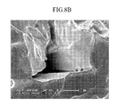
- FIG. 8B is a partial enlargement of the metal layer of FIG. 8A.
- FIGS. 8A and 8B It can be seen from FIGS. 8A and 8B that the metal layer was formed on the membrane in the form of nano nodules.
- a single cell was prepared according to Example 1, except that an Au metal layer was formed by performing Au sputtering onto a polymer electrolyte membrane on the side of the cathode instead of the anode side.
- a single cell was prepared according to Example 1, except that an Au metal layer was formed in the polymer electrolyte membrane on the side of the cathode as well, by performing Au sputtering onto the polymer electrolyte membrane on the side of the cathode.
- a commercial product NAFION 115 membrane having a thickness of 125 ⁇ m was rinsed with distilled water several times and treated with 1 liter of 2% hydrogen peroxide for 2 hours. The hydrogen peroxide was removed and the NAFION 115 membrane was rinsed with distilled water three times and treated again with 1 liter of 1 M sulfuric acid solution for 2 hours. The NAFION 115 membrane was rinsed again with distilled water and an H-type NAFION 115 membrane was thus prepared.
- 10wt% solid content of a composition for forming a catalyst layer was prepared by mixing 10g of Pt black (HISPEC ® 1000 produced by the Johnson Matthey Company), 10g of Pt/Ru black (HISPEC ® 6000 produced by the Johnson Matthey Company), 10g of water, 12wt% of a 5wt% concentration of NAFION solution, and 62g of isopropyl alcohol.
- the composition for forming a catalyst layer was sprayed onto one side of the polymer electrolyte membrane for coating.
- a catalyst layer area was 3.2X3.2 cm 2 and a catalyst loading quantity was 4 mg/cm 2 .
- the catalyst layer prepared as above became an anode catalyst layer.
- a cathode catalyst layer was formed on the other side of the polymer electrolyte membrane in the same method.
- an electrode substrate (uncatalyzed gas diffusion electrode, SGL Carbon 10DA) was prepared to have a microporous layer with a Vulcan black loading quantity of 1.4 mg/cm 2 by using a composition for forming a microporous layer including Vulcan black (VULCAN SDN 2).
- the electrode substrate was bonded with the polymer electrolyte membrane having the cathode catalyst layer by pressing the electrode substrate with a compression molder at 300 psi at 135°C for 3 minutes.
- an electrode substrate (uncatalyzed gas diffusion electrode, SGL Carbon 31 BC) without a microporous layer was physically bonded with the polymer electrolyte membrane having the anode catalyst layer to thereby prepare a membrane-electrode assembly.
- the membrane-electrode assembly was interposed between two gaskets, interposed again between two separators having a gas flow channel and a cooling channel of a predetermined shape, and then compressed between Cu end plates to thereby prepare a single cell.
- a commercial product NAFION 115 membrane having a thickness of 125 ⁇ m was rinsed with distilled water several times and treated with 1 liter of 2% hydrogen peroxide for 2 hours. The hydrogen peroxide was removed and the NAFION 115 membrane was rinsed with distilled water three times and treated again with 1 liter of 1 M sulfuric acid solution for 2 hours.
- the NAFION 115 membrane was rinsed again with distilled water and an H-type NAFION 115 membrane was thus prepared.
- a single cell was prepared according to Comparative Example 1, except that a pattern was formed on both sides of the NAFION 115 membrane through sandpapering, and the patterned NAFION 115 membrane was used as the polymer electrolyte membrane.
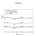
- Moisture retention properties of the polymer electrolyte membranes of Example 3 and Comparative Examples 1 and 2 were measured by using a differential scanning calorimeter (DSC).
- the moisture retention properties were measured after drying the polymer electrolyte membranes in a vacuum oven at 60°C for one hour, impregnating the polymer electrolyte membranes in distilled water at 60°C for one hour, and removing water from the polymer electrolyte membranes. The results are presented in FIGS. 9A and 9B.
- the polymer electrolyte membrane of Example 3 has a lower water ionic cluster transition peak temperature but a higher fusion heat than the polymer electrolyte membrane of Comparative Examples 1 and 2. It can be seen from the results that the reformed polymer electrolyte membrane has an excellent moisture retention property.
- Methanol crossover currents of the polymer electrolyte membranes prepared in accordance with Example 3 and Comparative Examples 1 and 2 were measured at 50°C and 60°C by flowing in 4ml of 1 M methanol and nitrogen 200 sccm (Standard Cubic Centimeter per Minute, cm 3 /min).
- the methanol permeability was calculated from the methanol crossover currents and the results are shown in the following Table 1.
- Table 1 Methanol permeability (cm 2 /S) 50°C 60°C Comparative Example 1 2.38x10 -6 3.03x10 -6 Comparative Example 2 2.23x10 -6 2.86x10 -6
- the polymer electrolyte membrane of Example 1 showed considerably low methanol permeability at 50°C and 60°C, compared to the polymer electrolyte membranes of Comparative Examples 1 and 2.
- CO stripping voltammetries of the membrane-electrode assemblies prepared in accordance with Example 3 and Comparative Example 1 were measured at 50°C and 70°C. The measurement results are shown in FIGS. 10A and 10B.
- FIG. 10A shows CO stripping voltammetry measurement results of the membrane-electrode assemblies prepared in accordance with Example 3 and Comparative Example 1 at 50°C
- FIG. 10B shows CO stripping voltammetry measurement results of the membrane-electrode assemblies prepared in accordance with Example 3 and Comparative Example 1 at 70°C.
- the CO oxidation initiation voltage of the catalyst in the membrane-electrode assembly including the surface-reformed polymer electrolyte membrane was lower than the CO oxidation initiation voltage of the catalyst in the membrane-electrode assembly of Comparative Example 1. Also, its current peak potential was lower as well. This is because the Au particles on the surface of the polymer electrolyte membrane weaken the connection force between PtRu catalyst and CO and suppresses catalyst poisoning.
- the fuel cells of Examples 1 to 3 having a metal layer and a polymer electrolyte membrane with rough morphology showed excellent methanol permeability and high power density, compared to the fuel cell of Comparative Example 1 using a pure NAFION membrane as a polymer electrolyte membrane and the fuel cell of Comparative Example 2 including a polymer electrolyte membrane having only surface roughness.
- Table 2 shows that the fuel cell of Example 1 having the metal layer only in the side of the anode had superior power density to the fuel cell of Example 2.
- One embodiment of the present invention provides a high-performance membrane-electrode assembly for a fuel cell that can improve interaction between the polymer electrolyte membrane and the catalyst by improving a contact area between the polymer electrolyte membrane and the catalyst and adherence between them, improve a moisture retention property of the polymer electrolyte membrane, and reduce crossover of fuel caused by deteriorated osmotic pressure.
Landscapes
- Chemical & Material Sciences (AREA)
- Chemical Kinetics & Catalysis (AREA)
- Electrochemistry (AREA)
- General Chemical & Material Sciences (AREA)
- Engineering & Computer Science (AREA)
- Manufacturing & Machinery (AREA)
- Materials Engineering (AREA)
- Ceramic Engineering (AREA)
- Life Sciences & Earth Sciences (AREA)
- Sustainable Development (AREA)
- Sustainable Energy (AREA)
- Fuel Cell (AREA)
- Inert Electrodes (AREA)
Abstract
Description
- The present invention relates to a membrane-electrode assembly for a fuel cell, a method of preparing the same, and a fuel cell system including the same.
- A fuel cell is a power generation system for producing electrical energy through an electrochemical redox reaction of an oxidant and a fuel such as hydrogen, or a hydrocarbon-based material such as methanol, ethanol, natural gas, and the like. Such a fuel cell is a clean energy source that can replace fossil fuels. It includes a stack composed of unit cells and produces various ranges of power output. Since it has four to ten times higher energy density than a small lithium battery, it has been highlighted as a small portable power source.
- Representative exemplary fuel cells include a polymer electrolyte membrane fuel cell (PEMFC) and a direct oxidation fuel cell (DOFC). The direct oxidation fuel cell includes a direct methanol fuel cell that uses methanol as a fuel.
- The polymer electrolyte fuel cell has an advantage of high energy density and high power, but it also has problems in the need to carefully handle hydrogen gas and the requirement of accessory facilities, such as a fuel reforming processor, for reforming hydrocarbon-based gases in order to produce hydrogen as the fuel gas.
- On the contrary, a direct oxidation fuel cell has a lower energy density than that of the gas-type fuel cell but has the advantages of easy handling of the liquid-type fuel, a low operation temperature, and no need for additional fuel reforming processors. Therefore, it has been acknowledged as an appropriate system for a portable power source for small and common electrical equipment.
- In the above-mentioned fuel cell system, the stack that generates electricity substantially includes several to many unit cells stacked adjacent to one another, and each unit cell is formed of a membrane-electrode assembly (MEA) and a separator (also referred to as a bipolar plate). The membrane-electrode assembly is composed of an anode (also referred to as a "fuel electrode" or an "oxidation electrode") and a cathode (also referred to as an "air electrode" or a "reduction electrode") that are separated by a polymer electrolyte membrane.
- A fuel is supplied to an anode and adsorbed on catalysts of the anode, and the fuel is oxidized to produce protons and electrons. The electrons are transferred into a cathode via an external circuit, and the protons are transferred into the cathode through the polymer electrolyte membrane. In addition, an oxidant is supplied to the cathode, and then the oxidant, protons, and electrons are reacted on catalysts of the cathode to produce electricity along with water.
- For the polymer electrolyte membrane, a perfluorosulfonic acid resin membrane (NAFION®) having good conductivity, mechanical properties, and chemical resistance has been commonly used. The perfluorosulfonic acid resin membrane has a thickness ranging from 130 to 180µm to inhibit crossover of a hydrocarbon fuel. However, the thicker the perfluorosulfonic acid resin membrane is, the worse the proton conductivity grows and the higher the cost of the polymer electrolyte membrane becomes.
- Particularly, a polymer electrolyte membrane that is thermally compressed with a platinum catalyst electrode undergoes a change of 15 to 30% in membrane thickness and volume depending on temperature and degree of hydration, and results in a volume change of over 200% maximum with 3 to 50wt% methanol as a fuel. Such a thickness increase of an electrolyte membrane applies a stress to a gas diffusion layer as an electrode substrate, and thus a dimension change in a surface direction induces a physical deterioration at the interface between catalyst particles and an electrolyte membrane during long term operation.
- One embodiment of the present invention provides a membrane-electrode assembly that has excellent adherence between a polymer electrolyte membrane and a catalyst layer, a good moisture retention property in a polymer electrolyte membrane, and that decreases fuel crossover due to an osmotic pressure decrease and thus improves cell performance.
- Another embodiment of the present invention provides a method of preparing the membrane-electrode assembly for a fuel cell.
- Yet another embodiment of the present invention provides a fuel cell system including the membrane-electrode assembly.
- According to an embodiment of the present invention, a membrane-electrode assembly is provided, which includes an anode and a cathode facing each other, i.e. disposed opposite to each other. The membrane-electrode assembly further includes a polymer electrolyte membrane having surface roughness on at least one side and being interposed between the anode and the cathode. A metal layer is randomly formed (disposed) on the at least one side of the polymer electrolyte membrane showing the mentioned surface roughness.
- According to yet another embodiment of the present invention, a method of fabricating a membrane-electrode assembly is provided, which includes the following steps:
- setting up a surface roughness on at least one side of a polymer electrolyte membrane through surface treatment;
- forming a metal layer on the at least one side of the polymer electrolyte membrane (20) showing the mentioned surface roughness; and
- forming an anode and a cathode on the polymer electrolyte membrane, respectively the metal layer.
- According to yet another embodiment of the present invention, a fuel cell system is provided, which includes an electricity generating element, a fuel supplier that supplies the electricity generating element with a fuel, and an oxidant supplier that supplies the electricity generating element with an oxidant. The electricity generating element includes the above mentioned membrane-electrode assembly and a separator positioned at each side of the membrane-electrode assembly, and generates electricity through electrochemical reactions of fuel and oxidants.
-
- FIG. 1 is a schematic cross-sectional view showing a membrane-electrode assembly according to an embodiment of the present invention;
- FIG. 2 is a schematic flowchart showing a process of fabricating a membrane-electrode assembly according to another embodiment of the present invention;
- FIG. 3 is a schematic diagram showing the structure of a fuel cell system according to another embodiment of the present invention;
- FIG. 4 is a scanning electron microscope (SEM) photograph showing a cross-section of a polymer electrolyte membrane after sandblasting surface-treatment during fabrication of a single cell according to Example 1;
- FIG. 5 is a SEM photograph showing a surface of a polymer electrolyte membrane after sandblasting surface-treatment during a fabrication of a single cell according to Example 1 (scale bar size: 40µm);
- FIG. 6 is a SEM photograph showing a surface of a metal layer that is disposed on a surface-treated polymer electrolyte membrane by Au sputtering during fabrication of a single cell according to Example 1 (scale bar size: 1 µm);
- FIG. 7 is a SEM photograph showing a surface of a metal layer that is disposed on a surface-treated polymer electrolyte membrane by Au sputtering during fabrication of a single cell according to Example 1 (scale bar size: 40µm);
- FIG. 8A is a SEM photograph showing a cross-section of a polymer electrolyte membrane that includes a metal layer disposed on a surface-treated polymer electrolyte membrane by Au sputtering during fabrication of a single cell according to Example 1;
- FIG. 8B is a partial enlarged view of the metal layer in FIG. 8A;
- FIG. 9A is a graph showing moisture retention properties of polymer electrolyte membranes prepared in accordance with Example 3 and Comparative Examples 1 and 2 by using a differential scanning calorimeter (DSC) after drying the polymer electrolyte membranes in a vacuum oven at 60°C for one hour;
- FIG. 9B is a graph showing moisture retention properties of polymer electrolyte membranes prepared in accordance with Example 3 and Comparative Examples 1 and 2 by using DSC after impregnating the polymer electrolyte membranes in distilled water at 60°C for one hour and then drying the polymer electrolyte membranes;
- FIG. 10A is a graph showing CO stripping voltammetry of membrane-electrode assemblies prepared in accordance with Example 3 and Comparative Example 1 at 50°C; and
- FIG. 10B is a graph showing CO stripping voltammetry of membrane-electrode assemblies prepared in accordance with Example 3 and Comparative Example 1 at 70°C.
- A membrane-electrode assembly of a fuel cell according to one embodiment of the present invention is composed of a polymer electrolyte membrane and an anode and a cathode disposed at both sides of the polymer electrolyte membrane. The membrane-electrode assembly generates electricity through oxidation of a fuel and reduction of an oxidant. The reactions of such a membrane-electrode assembly have been affected by adherence and contact areas at the interface between a polymer electrolyte membrane and an electrode. The higher the adherence and contact area is, the better the reactions occur.
- In general, the polymer electrolyte membrane is a perfluorosulfonic acid resin membrane. A thicker perfluorosulfonic acid resin membrane provides better dimensional stability and mechanical properties, but increased membrane resistance. A thinner membrane provides lower membrane resistance, but diminished mechanical properties whereby unreacted fuel gas and liquid tend to pass through the polymer membrane resulting in lost, unreacted fuel during operation and lower performance of the cell. Moreover, since hydrocarbon-based fuel is transferred to the cathode through a polymer electrolyte membrane and oxidized in a cathode in a direct oxidation fuel cell using hydrocarbon-based fuel such as methanol, ethanol, and propanol, the reduction space of an oxidant is reduced in the cathode and this degrades the battery performance.
- Therefore, it is desired to develop a technique for controlling an interface between the polymer electrolyte membrane and the electrode, and a technique for controlling the physical and chemical interface characteristics to prevent the durability of the membrane-electrode assembly from being deteriorated due to separation of the catalyst layer, and thus maximizing electrode catalyst efficiency.
- According to the present invention, it is possible to increase the adherence between the polymer electrolyte membrane and the catalyst layer, increase the contact area, improve moisture retention properties of the polymer electrolyte membrane, and reduce fuel crossover caused by decreased osmotic pressure. This may be accomplished by forming a membrane having appropriate surface roughness and randomly forming a metal layer on the membrane in the membrane-electrode assembly.
- FIG. 1 is a schematic cross-sectional view showing a membrane-electrode assembly according to an embodiment of the present invention.
- Referring to FIG. 1, a membrane-
electrode assembly 112 of the present invention includes apolymer electrolyte membrane 20 andelectrodes 30 and 30' for a fuel cell disposed on both sides of thepolymer electrolyte membrane 20. Metal layers 60 and 60' are randomly formed on at least one side of themembrane 20. Also, theelectrodes 30 and 30' include anelectrode substrate 50 or 50' and acatalyst layer 70 or 70' formed on the surface of the electrode substrate. - The
membrane 20 performs an ion exchange function, that is, it transfers protons generated in thecatalyst layer 70 of theanode 30 to the catalyst layer 70' of the cathode 30' in thepolymer electrolyte membrane 20. - In one embodiment, the
membrane 20 may have roughness on one side, or in another embodiment on both sides, to increase the contact area with themetal layer 60 and 60' and thecatalyst layer 70 or 70' of the electrode for high power output. Themembrane 20 may have an average surface roughness Ra in the range of 200nm to 2µm, and preferably in the range of 500nm to 2µm. When the average surface roughness of themembrane 20 is not more than 200nm, the active specific surface area with the catalyst layer is small and the adherence to the catalyst layer may be diminished after a long time. When the average surface roughness of themembrane 20 exceeds 2µm, the mechanical strength of themembrane 20 may be reduced, which is also not desirable. - One or both sides of the
membrane 20 may be patterned. The pattern formed in themembrane 20 may be a regular pattern. When the pattern is irregular, there may be non-uniform current and a reduction in the fuel cell performance. - In one embodiment, the
membrane 20 may have a thickness ranging from 50 to 150µm, in another embodiment from 110 to 140µm. When themembrane 20 is thinner than 50µm, the mechanical strength may be deteriorated. When it is thicker than 150µm, membrane resistance may be increased, which is not desirable. - The membrane may include a highly proton-conductive polymer. In one embodiment, the proton-conductive polymer may be a polymer resin having a cation exchange group selected from the group consisting of a sulfonic acid group, a carboxylic acid group, a phosphoric acid group, a phosphonic acid group, and derivatives thereof, at its side chain.
- In one embodiment, the proton-conductive polymer may include at least one selected from the group consisting of fluoro-based polymers, benzimidazole-based polymers, polyimide-based polymers, polyetherimide-based polymers, polyphenylenesulfide-based polymers, polysulfone-based polymers, polyethersulfone-based polymers, polyetherketone-based polymers, polyether-etherketone-based polymers, and polyphenylquinoxaline-based polymers. According to an embodiment, the polymer electrolyte membrane includes proton conductive polymers selected from the group consisting of poly(perfluorosulfonic acid) (NAFION®), poly(perfluorocarboxylic acid), a copolymer of tetrafluoroethylene and fluorovinylether having a sulfonic acid group, defluorinated polyetherketone sulfide, aryl ketone, poly(2,2'-(m-phenylene)-5,5'-bibenzimidazole), and poly(2,5-benzimidazole).
- H in an ion exchange group of the proton conductive polymer can be replaced with Na, K, Li, Cs, or tetrabutyl ammonium. When the H is substituted by Na in an ion exchange group at the terminal end of the proton conductive polymer, NaOH is used. When the H is replaced with tetrabutylammonium, tributylammonium hydroxide is used. K, Li, or Cs can also be replaced by using appropriate compounds. Since a method of substituting H is widely known in this related art, detailed description thereof will not be provided herein.
- The
membrane 20 includes the metal layers 60 and 60' randomly disposed in at least one side. Randomly disposed means that the metal layers 60 and 60' do not form a closed layer covering themembrane 20; the metal layers 60 and 60' are still transparent for the moisture. - The metal layers 60 and 60' disposed on one or both sides of the
membrane 20 not only improve cooperative performance between themembrane 20 and the catalyst layers 70 and 70', but also reduce crossover of fuel. Therefore, it is desirable to dispose the metal layers on both sides of themembrane 20, instead of forming a metal layer on any one side of themembrane 20. In an embodiment, when it is disposed on one side, it is desirable to dispose the metal layer on a side adjacent to the anode. - In one embodiment, the metal layers 60 and 60' may be randomly disposed in the
membrane 20 in the form of a nano nodule or a nano horn. In another embodiment, the metal layers 60 and 60' are formed in the shape of a nano nodule. When a metal layer has the shape of a nano nodule, the metal layer is porous and this is advantageous because the morphology of the metal layer interface is increased three-dimensionally. In other words, the metal layers 60 and 60' are porous; i.e. that the moisture can easily pass the metal layers 60 and 60'. Therefore, the metal layers 60 and 60' are deposited such on thepolymer electrolyte membrane 20 that they are porous. - In one embodiment, the metal layers 60 and 60' include or consist of at least one metal selected from Au, Pt, Ru, W, Pd, Fe, and alloys thereof. Preferably, the metal layers 60 and 60' include or consist of Au.
- As described above, the metal included in the metal layers 60 and 60' functions as a catalyst, and since it has a nano particle size, it increases the moisture retention property of the
polymer electrolyte membrane 20 to thereby maintain the humidity of thepolymer electrolyte membrane 20 at a predetermined level at a high temperature. - Also, the metal in the metal layers 60 and 60' directly increases the number of oxide species quantitatively through a bifunctional mechanism with respect to electro-oxidation. Thus, it is possible to improve an electrode activity for an oxidation reaction of fuel.
- In one embodiment, the
membrane 20 and the metal layers 60 and 60' may have a thickness ratio of 25:1 to 1500:1, and in another embodiment 100:1 to 260:1. When the thickness ratio of the membrane to the metal layer is within the range, the co-catalytic effect of the metal element in the metal layer is maximized. Since the porous state is maintained, the specific surface area is increased, which is desirable. When the thickness ratio is out of the range, the density of the metal layer is increased. Since this allows less access of fuel, it is not desirable. - In one embodiment, the metal layers 60 and 60' may have a thickness in the range of 100nm to 2µm, and in another embodiment from 500nm to 1 µm. When the metal layer is thinner than 100nm, the effect obtained from the formation of the metal layer may be insignificant. When the metal layer is thicker than 2µm, it provides narrow paths for fuel.
- An
anode 30 and a cathode 30' are disposed on respective sides of the polymer electrolyte membrane. - At least one of the
anode 30 and the cathode 30' includeselectrode substrates 50 and 50' and catalyst layers 70 and 70' disposed on theelectrode substrates 50 and 50'. - The electrode substrates 50 and 50' of the anode and cathode support the
anode 30 and cathode 30', respectively, and provide a path for transferring fuel and oxidant to the catalyst layers 70 and 70'.Such electrode substrates 50 and 50' may be conductive substrates. As for theelectrode substrates 50 and 50', a conductive substrate is used, for example carbon paper, carbon cloth, carbon felt, and metal cloth (a porous film including a metal cloth fiber or a metalized polymer fiber), but it is not limited thereto. - The electrode substrates 50 and 50' may be treated with a fluorine-based resin to be water-repellent to prevent deterioration of diffusion efficiency due to water generated during operation of a fuel cell. In one embodiment, the fluorine-based resin may be one selected from the group consisting of polytetrafluoroethylene, polyvinylidene fluoride, polyhexafluoro propylene, polyperfluoroalkylvinylether, polyperfluoro sulfonylfluoride alkoxyvinyl ether, fluorinated ethylene propylene, polychlorotrifluoro ethylene, and copolymers thereof, but it is not limited thereto.
- A microporous layer (MPL, not shown) can be added between the
aforementioned electrode substrates 50 and 50' and catalyst layer to increase reactant diffusion effects. The microporous layer generally includes conductive powders with a particular particle diameter. In one embodiment, the conductive material may include, but is not limited to, carbon powder, carbon black, acetylene black, activated carbon, carbon fiber, fullerene, nano-carbon, or combinations thereof. The nano-carbon may include a material such as carbon nanotubes, carbon nanofiber, carbon nanowire, carbon nanohorns, carbon nanorings, or combinations thereof. - The microporous layer is formed by coating a composition comprising a conductive powder, a binder resin, and a solvent on the conductive substrate. In one embodiment, the binder resin may include, but is not limited to, polytetrafluoro ethylene, polyvinylidene fluoride, polyhexafluoro propylene, polyperfluoroalkylvinyl ether, polyperfluoro sulfonylfluoride alkoxy vinyl ether, polyvinyl alcohol, cellulose acetate, or copolymers thereof. In one embodiment, the solvent may include, but is not limited to, an alcohol such as ethanol, isopropyl alcohol, n-propyl alcohol, butanol and so on, water, dimethyl acetamide, dimethyl sulfoxide, N-methylpyrrolidone, and tetrahydrofuran. In one embodiment, the coating method may include, but is not limited to, screen printing, spray coating, doctor blade methods, gravure coating, dip coating, silk screening, painting, and so on, depending on the viscosity of the composition.
- The catalyst layers 70 and 70' are disposed on the
electrode substrates 50 and 50'. - The catalyst layers 70 and 70' include catalysts to promote related reactions, such as fuel oxidation and oxidant reduction.
- The catalysts may be any catalyst that can promote a fuel cell reaction. For example, platinum-based catalysts are generally used. In one embodiment, examples of the platinum-based catalysts include platinum, ruthenium, osmium, platinum-ruthenium alloys, platinum-osmium alloys, platinum-palladium alloys, platinum-M alloys, and combinations thereof, where M is a transition element selected from the group consisting of Ga, Ti, V, Cr, Mn, Fe, Co, Ni, Cu, Zn, Sn, Mo, W, Rh, and combinations thereof. According to an embodiment, platinum-based catalysts may include Pt, Pt/Ru, Pt/W, Pt/Ni, Pt/Sn, Pt/Mo, Pt/Pd, Pt/Fe, Pt/Cr, Pt/Co, Pt/Ru/W, Pt/Ru/Mo, Pt/Ru/V, Pt/Fe/Co, Pt/Ru/Rh/Ni, Pt/Ru/Sn/W, and combinations thereof.
- The metal catalyst may be supported on a carrier, or it may be a black type of catalyst that is not supported on a carrier. In one embodiment, the carrier may include carbon-based materials such as graphite, denka black, ketjen black, acetylene black, carbon nanotubes, carbon nanofiber, carbon nanowire, carbon nanoballs, and activated carbon. In one embodiment, for a carrier, an inorganic particulate such as alumina, silica, zirconia, and titania may also be used. A carbon-based material is generally used as a carrier.
- The catalyst layers 70 and 70' may further include a binder resin to improve adherence of catalyst layers and proton conductivity.
- In one embodiment, the binder resin may be a proton-conductive polymer resin having a cation exchange group selected from the group consisting of a sulfonic acid group, a carboxylic acid group, a phosphoric acid group, a phosphonic acid group, and derivatives thereof, at its side chain. In an embodiment, the proton-conductive polymer may include at least one selected from the group consisting of fluoro-based polymers, benzimidazole-based polymers, polyimide-based polymers, polyetherimide-based polymers, polyphenylenesulfide-based polymers polysulfone-based polymers, polyethersulfone-based polymers, polyetherketone-based polymers, polyether-etherketone-based polymers, and polyphenylquinoxaline-based polymers. In another embodiment, the polymer electrolyte membrane includes proton conductive polymers selected from the group consisting of poly(perfluorosulfonic acid) (NAFION®), poly(perfluorocarboxylic acid), a copolymer of tetrafluoroethylene and fluorovinylether having a sulfonic acid group, defluorinated polyetherketone sulfide, aryl ketone, poly(2,2'-(m-phenylene)-5,5'-bibenzimidazole), or poly(2,5-benzimidazole).
- The binder resins may be used singularly or in combination. They may be used along with non-conductive polymers to improve adherence with a polymer electrolyte membrane. The binder resins may be used in a controlled amount adapted to their purposes.
- Non-limiting examples of the non-conductive polymers include polytetrafluoroethylene (PTFE), tetrafluoroethylene-hexafluoropropylene copolymers (FEP), tetrafluoroethylene-perfluoro alkyl vinylether copolymers (PFA), ethylene/tetrafluoroethylene (ETFE), chlorotrifluoroethylene-ethylene copolymers (ECTFE), polyvinylidene fluoride, polyvinylidenefluoride-hexafluoropropylene copolymers (PVdF-HFP), dodecylbenzene sulfonic acid, sorbitol, or combinations thereof.
- FIG. 2 is a view describing a preparation method of a membrane-electrode assembly in accordance with an embodiment of the present invention.
- Referring to FIG. 2, the membrane-electrode assembly may be prepared by forming roughness on the surface of the membrane through a surface treatment at step S1, forming a metal layer on the membrane having a rough surface to thereby form a polymer electrolyte membrane at step S2, and forming an anode and a cathode on the polymer electrolyte membrane at step S3.
- First, a polymer electrolyte membrane is prepared. A method for forming the membrane is not limited to a specific method, and the membrane can be fabricated in the form of a thin film by using a conventional fabrication method and proton-conductive cation exchange resin. The proton-conductive cation exchange resin may be the same as described above.
- Subsequently, roughness is formed on the surface of the membrane through surface treatment at step S1. As for the surface treatment, a conventional patterning method may be used. In one embodiment, the surface treatment may be one selected from the group consisting of sandpapering, sandblasting, corona treatment, rubbing, compressing, a plasma method, electron beam irradiation, and combinations thereof. In another embodiment, the surface treatment may be sandpapering.
- The patterning of the membrane may be performed on one or both sides of the membrane, and in an embodiment, the patterning is performed on both sides of the membrane.
- Subsequently, a metal layer is disposed on the membrane having the roughness to thereby prepare a polymer electrolyte membrane at step S2.
- In an embodiment, the metal layer is formed on the membrane by using a method selected from the group consisting of sputtering, Physical Vapor Deposition (PVD), Chemical Vapor Deposition (CVD), Plasma Enhanced Chemical Vapor Deposition (PECVD), Thermal Chemical Vapor Deposition (TCVD), electron beam evaporation, vacuum thermal evaporation, laser ablation, thermal evaporation, e-beam evaporation, and combinations thereof. In another embodiment, the metal layer is disposed by using the sputtering method.
- When the metal layer is disposed by the sputtering method, in one embodiment, it is desirable to apply a current in the range of 3 to 9mA, and in another embodiment from 5 to 7mA. When the current is lower than 3mA, the density of the metal layer is increased and thus the metal layer provides narrower paths for fuel. When the current is higher than 7mA, the porosity of the metal layer is increased and thus the mechanical strength of the metal layer may be deteriorated.
- In one embodiment, the sputtering may be performed for 50 to 300 seconds, and in another embodiment for 50 to 250 seconds. When the sputtering is performed for less than 50 seconds, the porosity of the metal layer is excessively increased and the mechanical strength is deteriorated. When the sputtering is performed for longer than 300 seconds, the density of the metal layer is increased too much to provide appropriate paths for fuel.
- As described above, the metal layer may be formed to have a thickness ratio in the range of 25:1 to 1500:1.
- Subsequently, the preparation of the membrane-electrode assembly is completed by forming an anode and a cathode in the polymer electrolyte membrane at step S3.
- The anode and the cathode of the membrane-electrode assembly may be made by forming a catalyst layer on the polymer electrolyte membrane and bonding it with an electrolyte substrate, or by bonding the polymer electrolyte membrane with an electrode substrate having a catalyst layer disposed thereon.
- Particularly, according to an embodiment of the present invention, the catalyst layer is formed on the prepared polymer electrolyte membrane by coating the polymer electrolyte with a composition for forming the catalyst layer, or coating a releasing film with the composition for forming the catalyst layer and drying the film to thereby form a first catalyst layer, transferring the first catalyst layer to the polymer electrolyte membrane through thermal pressing to thereby form a catalyst layer, and bonding the catalyst layer with the electrode substrate.
- According to another embodiment, the membrane-electrode assembly may be fabricated by coating an electrode substrate with a composition for forming the catalyst layer to thereby form the catalyst layer and bonding the electrode substrate having the catalyst layer formed thereon with the above-prepared polymer electrolyte membrane.
- In one embodiment, when both sides of the polymer electrolyte membrane are directly coated with the composition for forming a catalyst layer, the coating may be performed in a method selected from the group consisting of screen printing, spray coating, doctor blade coating, gravure coating, dip coating, silk screening, painting, slot dying, and combinations thereof according to the viscosity of the composition, but the coating method is not limited thereto. In another embodiment, the coating may be performed by screen printing.
- Also, when the catalyst layer is formed by coating the composition for forming a catalyst layer on only one side of a releasing film and drying the film coated with the composition and then the catalyst layer is transferred to the polymer electrolyte membrane, in one embodiment, the releasing film used therein may be a fluorinated resin film having a thickness of approximately 200µm such as polytetrafluoroethylene (PTFE), a tetrafluoroethylene-hexafluoropropylene copolymer (FEP), a tetrafluoroethylene-perfluoro alkylvinylether copolymer (PFA), and ethylene/tetrafluoroethylene (ETFE), or the releasing film may be non-fluorinated resin film such as polyimide (KAPTON® produced by the DuPont Company) and polyester (MYAR® produced by the DuPont Company). The releasing film is coated with the composition for forming a catalyst layer in the method described above.
- The transferring process may be performed by disposing the catalyst layer formed in the releasing film onto the polymer electrolyte membrane and then compressing them while applying heat thereto.
- In one embodiment, the thermal pressing may be performed at a temperature in the range of from 100 to 250°C, and in another embodiment from 100 to 200°C. Also, in an embodiment, the thermal pressing may be performed by applying pressure in the range of 300 to 2000 psi, and in another embodiment from 300 to 1500 psi.
- The transferring of the catalyst layer is smoothly performed within the temperature and pressure ranges. Out of the ranges, the transferring of the catalyst layer may not be performed perfectly or the catalyst layer becomes too dense to transfer reactant therethrough.
- Since the electrode substrate and the catalyst layer are as described above and an exemplary method for bonding the electrode substrate with the polymer electrolyte membrane is widely known to those skilled in the art of the present invention, a detailed description thereof will not be provided herein.
- The above-prepared membrane-electrode assembly includes the membrane having appropriate roughness on the surface through a surface treatment, and a metal layer formed on the membrane. Therefore, the contact area and the adherence between the polymer electrolyte membrane and the catalyst layer are increased, and the moisture retention property of the polymer electrolyte membrane is improved. Also, the crossover of fuel caused by decreased osmotic pressure can be reduced and this brings about excellent fuel cell characteristics.
- Another embodiment of the present invention provides a fuel cell system including the above membrane-electrode assembly.
- In one embodiment, a fuel cell system of the present invention includes at least one of an electricity generating element, a fuel supplier, and an oxidant supplier.
- The electricity generating element includes a membrane-electrode assembly that includes a polymer electrolyte membrane and a cathode and an anode positioned at both sides of the polymer electrolyte membrane, and separators positioned at both sides of the membrane-electrode assembly. The electricity generating element generates electricity through oxidation of a fuel and reduction of an oxidant.
- The fuel supplier supplies the electricity generating element with a fuel including hydrogen, and the oxidant supplier supplies the electricity generating element with an oxidant. The oxidant includes oxygen or air.
- In one embodiment, the fuel includes liquid or gaseous hydrogen, or a hydrocarbon-based fuel such as methanol, ethanol, propanol, butanol, or natural gas.
- FIG. 3 shows a schematic structure of a
fuel cell system 100 that will be described in detail with reference to this accompanying drawing as follows. FIG. 3 illustrates a fuel cell system wherein a fuel and an oxidant are provided to theelectricity generating element 115 throughpumps - The
fuel cell system 100 includes at least oneelectricity generating element 115 that generates electrical energy through an electrochemical reaction of a fuel and an oxidant, afuel supplier 120 for supplying a fuel to theelectricity generating element 115, and anoxidant supplier 130 for supplying an oxidant to theelectricity generating element 115. - In addition, the
fuel supplier 120 is equipped with atank 122 that stores fuel, and afuel pump 124, which is connected to thefuel tank 122. Thefuel pump 124 supplies fuel stored in thetank 122 to afuel cell stack 110. - The
oxidant supplier 130, which supplies theelectricity generating element 115 with an oxidant, is equipped with at least onepump 132 for supplying an oxidant to thestack 110. - The
electricity generating element 115 includes a membrane-electrode assembly 112, which oxidizes hydrogen or a fuel and reduces an oxidant, andseparators 114 and 114' that are respectively positioned at opposite sides of the membrane-electrode assembly and supply hydrogen or a fuel, and an oxidant, respectively. At least oneelectricity generating element 115 constitutes thestack 110. - The following examples illustrate the present invention in more detail. However, it is understood that the present invention is not limited by these examples.
- For a membrane, a
commercial product NAFION 115 membrane having a thickness of 125µm was rinsed with distilled water several times and treated with 1 liter of 2% hydrogen peroxide for 2 hours. Subsequently, the hydrogen peroxide was removed by rinsing with distilled water three times, and then theNAFION 115 membrane was treated with 1 liter of 1 M sulfuric acid solution for 2 hours. TheNAFION 115 membrane was rinsed with distilled water again, such that an H-type NAFION 115 membrane was prepared. - Both sides of the
NAFION 115 membrane were sandblasted to form a pattern. One side of the patternedNAFION 115 membrane toward the anode was sputtered with Au at 20°C for 100 seconds to thereby form an Au metal layer having a thickness of 500nm and prepare a polymer electrolyte membrane. - 10wt% solid content of a composition for forming a catalyst layer was prepared by mixing 10g of Pt black (HISPEC® 1000 produced by the Johnson Matthey Company), 10g of Pt/Ru black (HISPEC® 6000 produced by the Johnson Matthey Company), 10g of water, 12wt% of a 5wt% concentration of NAFION solution, and 62g of isopropyl alcohol. The composition for forming a catalyst layer was sprayed onto the Au sputtered polymer electrolyte membrane. Herein, the catalyst layer area was 3.2X3.2 cm2 and the catalyst loading quantity was 4mg/cm2. The catalyst layer prepared as above became an anode catalyst layer. A cathode catalyst layer was formed by performing the same process onto the other side of the polymer electrolyte membrane.
- Subsequently, an electrode substrate (uncatalyzed gas diffusion electrode, SGL Carbon 10DA) was prepared to have a microporous layer with a Vulcan black loading quantity of 1.4mg/cm2 by using a composition for forming a microporous layer including Vulcan black (VULCAN SDN 2). The electrode substrate was bonded with the polymer electrolyte membrane having the cathode catalyst layer by pressing the electrode substrate with a compression molder at 300 psi and 135°C for 3 minutes. Also, an electrode substrate (uncatalyzed gas diffusion electrode, SGL Carbon 31 BC) without a microporous layer was physically bonded with the polymer electrolyte membrane having the anode catalyst layer to thereby prepare a membrane-electrode assembly. The membrane-electrode assembly was interposed between two gaskets, interposed again between two separators having a predetermined gas flow channel and a cooling channel, and then compressed between Cu end plates to thereby prepare a single cell.
- FIG. 4 is a scanning electron microscope (SEM) photograph showing a cross-section of the membrane after sandblasting was performed on the polymer electrolyte membrane in the single cell preparation process in accordance with Example 1 of the present invention. FIG. 5 is a SEM photograph showing the surface of the membrane.
- It can be seen from FIGS. 4 and 5 that the surface roughness was increased in the cross-section of the membrane due to the sandblasting surface treatment.
- FIG. 6 is a SEM photograph (scale bar size: 1 µm) showing the surface of the metal layer disposed on the membrane by performing Au sputtering onto the surface-treated polymer electrolyte membrane in the single cell preparation process of Example 1. FIG. 7 is a SEM photograph (scale bar size: 40µm) showing the surface of the membrane.
- In FIG. 6, white parts are Au. In short, it can be seen from FIG. 6 that Au exists in the shape of an island on the metal layer.
- Also, it can be seen from FIG. 7 that the Au metal layer formed on the sandblasted membrane also has roughness on the surface.
- FIG. 8A is a SEM photograph showing a cross-section of the metal layer disposed on the membrane through Au sputtering onto the surface-treated polymer electrolyte membrane in the single cell preparation process of Example 1. FIG. 8B is a partial enlargement of the metal layer of FIG. 8A.
- It can be seen from FIGS. 8A and 8B that the metal layer was formed on the membrane in the form of nano nodules.
- A single cell was prepared according to Example 1, except that an Au metal layer was formed by performing Au sputtering onto a polymer electrolyte membrane on the side of the cathode instead of the anode side.
- A single cell was prepared according to Example 1, except that an Au metal layer was formed in the polymer electrolyte membrane on the side of the cathode as well, by performing Au sputtering onto the polymer electrolyte membrane on the side of the cathode.
- As for a membrane, a
commercial product NAFION 115 membrane having a thickness of 125µm was rinsed with distilled water several times and treated with 1 liter of 2% hydrogen peroxide for 2 hours. The hydrogen peroxide was removed and theNAFION 115 membrane was rinsed with distilled water three times and treated again with 1 liter of 1 M sulfuric acid solution for 2 hours. TheNAFION 115 membrane was rinsed again with distilled water and an H-type NAFION 115 membrane was thus prepared. - 10wt% solid content of a composition for forming a catalyst layer was prepared by mixing 10g of Pt black (HISPEC® 1000 produced by the Johnson Matthey Company), 10g of Pt/Ru black (HISPEC® 6000 produced by the Johnson Matthey Company), 10g of water, 12wt% of a 5wt% concentration of NAFION solution, and 62g of isopropyl alcohol. The composition for forming a catalyst layer was sprayed onto one side of the polymer electrolyte membrane for coating. Herein, a catalyst layer area was 3.2X3.2 cm2 and a catalyst loading quantity was 4 mg/cm2. The catalyst layer prepared as above became an anode catalyst layer. A cathode catalyst layer was formed on the other side of the polymer electrolyte membrane in the same method.
- Subsequently, an electrode substrate (uncatalyzed gas diffusion electrode, SGL Carbon 10DA) was prepared to have a microporous layer with a Vulcan black loading quantity of 1.4 mg/cm2 by using a composition for forming a microporous layer including Vulcan black (VULCAN SDN 2). The electrode substrate was bonded with the polymer electrolyte membrane having the cathode catalyst layer by pressing the electrode substrate with a compression molder at 300 psi at 135°C for 3 minutes. Also, an electrode substrate (uncatalyzed gas diffusion electrode, SGL Carbon 31 BC) without a microporous layer was physically bonded with the polymer electrolyte membrane having the anode catalyst layer to thereby prepare a membrane-electrode assembly. The membrane-electrode assembly was interposed between two gaskets, interposed again between two separators having a gas flow channel and a cooling channel of a predetermined shape, and then compressed between Cu end plates to thereby prepare a single cell.
- As for a membrane, a
commercial product NAFION 115 membrane having a thickness of 125µm was rinsed with distilled water several times and treated with 1 liter of 2% hydrogen peroxide for 2 hours. The hydrogen peroxide was removed and theNAFION 115 membrane was rinsed with distilled water three times and treated again with 1 liter of 1 M sulfuric acid solution for 2 hours. - The
NAFION 115 membrane was rinsed again with distilled water and an H-type NAFION 115 membrane was thus prepared. A single cell was prepared according to Comparative Example 1, except that a pattern was formed on both sides of theNAFION 115 membrane through sandpapering, and the patternedNAFION 115 membrane was used as the polymer electrolyte membrane. - Moisture retention properties of the polymer electrolyte membranes of Example 3 and Comparative Examples 1 and 2 were measured by using a differential scanning calorimeter (DSC).
- The moisture retention properties were measured after drying the polymer electrolyte membranes in a vacuum oven at 60°C for one hour, impregnating the polymer electrolyte membranes in distilled water at 60°C for one hour, and removing water from the polymer electrolyte membranes. The results are presented in FIGS. 9A and 9B.
- As shown in FIGS. 9A and 9B, the polymer electrolyte membrane of Example 3 has a lower water ionic cluster transition peak temperature but a higher fusion heat than the polymer electrolyte membrane of Comparative Examples 1 and 2. It can be seen from the results that the reformed polymer electrolyte membrane has an excellent moisture retention property.
- Methanol crossover currents of the polymer electrolyte membranes prepared in accordance with Example 3 and Comparative Examples 1 and 2 were measured at 50°C and 60°C by flowing in 4ml of 1 M methanol and
nitrogen 200 sccm (Standard Cubic Centimeter per Minute, cm3/min). The methanol permeability was calculated from the methanol crossover currents and the results are shown in the following Table 1.Table 1 Methanol permeability (cm2/S) 50° C 60°C Comparative Example 1 2.38x10⁻⁶ 3.03x10⁻⁶ Comparative Example 2 2.23x10⁻⁶ 2.86x10⁻⁶ Example 1 2.07x10⁻⁶ 2.57x10⁻⁶ - As shown in Table 1, the polymer electrolyte membrane of Example 1 showed considerably low methanol permeability at 50°C and 60°C, compared to the polymer electrolyte membranes of Comparative Examples 1 and 2.
- CO stripping voltammetries of the membrane-electrode assemblies prepared in accordance with Example 3 and Comparative Example 1 were measured at 50°C and 70°C. The measurement results are shown in FIGS. 10A and 10B.
- FIG. 10A shows CO stripping voltammetry measurement results of the membrane-electrode assemblies prepared in accordance with Example 3 and Comparative Example 1 at 50°C, and FIG. 10B shows CO stripping voltammetry measurement results of the membrane-electrode assemblies prepared in accordance with Example 3 and Comparative Example 1 at 70°C.
- As shown in FIGS. 10A and 10B, the CO oxidation initiation voltage of the catalyst in the membrane-electrode assembly including the surface-reformed polymer electrolyte membrane was lower than the CO oxidation initiation voltage of the catalyst in the membrane-electrode assembly of Comparative Example 1. Also, its current peak potential was lower as well. This is because the Au particles on the surface of the polymer electrolyte membrane weaken the connection force between PtRu catalyst and CO and suppresses catalyst poisoning.
- Power density of the unit cells prepared in accordance with Examples 1 to 3 and Comparative Examples 1 and 2 were measured at 60 and 70 respectively by providing 1 M methanol and ambient air with anode and cathode of the unit cells. The measurement results are shown in the following Table 2.
Table 2 Example 1 Example 2 Example 3 Comparative Example 1 Comparative Example 2 Power density at 60°C (mW/cm2) 0.45V 81 77 64 72 67 0.40V 105 104 93 90 92 Max. 117 125 114 108 112 Power density at 70°C (mW/cm2) 0.45V 108 93 86 91 82 0.40V 138 128 117 113 115 Max. 154 164 154 133 151 - As illustrated in Table 2, the fuel cells of Examples 1 to 3 having a metal layer and a polymer electrolyte membrane with rough morphology showed excellent methanol permeability and high power density, compared to the fuel cell of Comparative Example 1 using a pure NAFION membrane as a polymer electrolyte membrane and the fuel cell of Comparative Example 2 including a polymer electrolyte membrane having only surface roughness. In addition, Table 2 shows that the fuel cell of Example 1 having the metal layer only in the side of the anode had superior power density to the fuel cell of Example 2.
- One embodiment of the present invention provides a high-performance membrane-electrode assembly for a fuel cell that can improve interaction between the polymer electrolyte membrane and the catalyst by improving a contact area between the polymer electrolyte membrane and the catalyst and adherence between them, improve a moisture retention property of the polymer electrolyte membrane, and reduce crossover of fuel caused by deteriorated osmotic pressure.
Claims (21)
- A membrane-electrode assembly (112) for a fuel cell, comprising:an anode and a cathode (30, 30') disposed opposite to each other;a polymer electrolyte membrane (20) having surface roughness on at least one side and being interposed between the anode and the cathode (30, 30'), anda metal layer (60, 60') randomly formed on the at least one side of the polymer electrolyte membrane (20) showing the mentioned surface roughness.
- The membrane-electrode assembly of claim 1, wherein the membrane has an average surface roughness in the range of 200nm to 2µm.
- The membrane-electrode assembly of claim 1, wherein the polymer electrolyte membrane (20) is patterned on both sides thereof.
- The membrane-electrode assembly of claims 1 or 2, wherein the polymer electrolyte membrane (20) comprises a polymer resin having proton conductivity.
- The membrane-electrode assembly of any of the preceding claims, wherein the polymer electrolyte membrane (20) comprises a polymer resin having a cation exchange group at its side chain selected from the group consisting of a sulfonic acid group, a carboxylic acid group, a phosphoric acid group, a phosphonic acid group, and derivatives thereof.
- The membrane-electrode assembly of any of the preceding claims, wherein the metal layer (60, 60') has a form of a nano nodule.
- The membrane-electrode assembly of any of claims 1, 2, 4 and 5, wherein the metal layer (60, 60') is disposed on one side of the polymer electrolyte membrane (20) adjacent to the anode.
- The membrane-electrode assembly of any of the preceding claims, wherein the metal layer (60, 60') comprises a metal selected from the group consisting of Au, Pt, Ru, W, Pd, Fe, and alloys thereof.
- The membrane-electrode assembly of any of the preceding claims, wherein the polymer electrolyte membrane (20) and the metal layer (60, 60') have a thickness ratio in the range of 25:1 to 1500:1.
- The membrane-electrode assembly of any of the preceding claims, wherein the metal layer (60, 60') has a thickness in the range of 100nm to 2µm.
- A method for fabricating a membrane-electrode assembly (112) for a fuel cell, comprising the steps of:setting up a surface roughness on at least one side of a polymer electrolyte membrane (20) through surface treatment;forming a metal layer (60, 60') on the at least one side of the polymer electrolyte membrane (20) showing the mentioned surface roughness; andforming an anode and a cathode on the polymer electrolyte membrane (20), respectively the metal layer (60, 60').
- The method of claim 11, wherein the polymer electrolyte membrane (20) comprises a cation exchange resin having proton conductivity.
- The method of claims 11 or 12, wherein the surface treatment is performed in a method selected from the group consisting of sandpapering, sandblasting, corona treatment, rubbing, pressing, plasma treatment, electron beam irradiation, and combinations thereof.
- The method of any of claims 11 to 13, wherein the metal is selected from the group consisting of Au, Pt, Ru, W, Pd, Fe, and alloys thereof.
- The method of any of claims 11 to 14, wherein the metal layer (60, 60') is formed by a method selected from the group consisting of sputtering, physical vapor deposition, chemical vapor deposition, plasma enhancement chemical deposition, thermal chemical deposition, ion beam evaporation, vacuum thermal evaporation, laser ablation, thermal evaporation, electron beam evaporation, and combinations thereof.
- The method of claim 15, wherein the metal layer (60, 60') is formed using sputtering while applying a current in a range of 3 to 9mA.
- The method of claims 15 or 16, wherein the metal layer (60, 60') is formed by performing sputtering for 50 to 300 seconds.
- The method of any of claims 11 to 17, wherein the polymer electrolyte membrane (20) and the metal layer (60, 60') have a thickness ratio in the range of 25:1 to 1500:1.
- The method of any of claims 11 to 18, wherein the metal layer (60, 60') has a thickness in the range of 100nm to 2µm.
- The method of any of claims 11 to 19, wherein a catalyst layer (70, 70') is formed on the polymer electrolyte membrane (20), respectively the metal layer (60, 60') and the polymer electrolyte membrane (20), respectively the metal layer (60, 60') with the catalyst layer (70, 70') is bonded with an electrode substrate (50, 50'), or an electrode substrate (50, 50') with a catalyst layer (70, 70') formed therein is bonded with athepolymer electrolyte membrane (20), respectively the metal layer (60, 60').
- A fuel cell system comprising:at least one electricity generating element adapted to generate electricity through an electrochemical reaction between a fuel and an oxidant, and that comprisesa membrane-electrode assembly (112) according to any of claims 1 to 10;separators disposed on each side of the membrane-electrode assembly (112);a fuel supplier adapted for supplying the fuel to the electricity generating element; andan oxidant supplier adapted for supplying the oxidant to the electricity generating element.
Applications Claiming Priority (1)
| Application Number | Priority Date | Filing Date | Title |
|---|---|---|---|
| KR1020060083524A KR20080020259A (en) | 2006-08-31 | 2006-08-31 | Membrane-electrode assembly for fuel cell, method for manufacturing same and fuel cell system comprising same |
Publications (2)
| Publication Number | Publication Date |
|---|---|
| EP1914825A1 true EP1914825A1 (en) | 2008-04-23 |
| EP1914825B1 EP1914825B1 (en) | 2011-02-23 |
Family
ID=38653573
Family Applications (1)
| Application Number | Title | Priority Date | Filing Date |
|---|---|---|---|
| EP07115015A Ceased EP1914825B1 (en) | 2006-08-31 | 2007-08-27 | Membrane-electrode assembly for fuel cell, method of preparing same, and fuel cell system comprising same |
Country Status (6)
| Country | Link |
|---|---|
| US (1) | US20080268314A1 (en) |
| EP (1) | EP1914825B1 (en) |
| JP (1) | JP5383015B2 (en) |
| KR (1) | KR20080020259A (en) |
| CN (1) | CN101136480B (en) |
| DE (1) | DE602007012631D1 (en) |
Families Citing this family (18)
| Publication number | Priority date | Publication date | Assignee | Title |
|---|---|---|---|---|
| WO2009069685A1 (en) * | 2007-11-27 | 2009-06-04 | Honda Motor Co., Ltd. | Free-standing membrane electrolyte electrode assembly |
| JP2012164646A (en) * | 2011-01-17 | 2012-08-30 | Sumitomo Chemical Co Ltd | Membrane electrode assembly and fuel cell |
| CA2920507C (en) * | 2013-08-14 | 2021-07-13 | Commonwealth Scientific And Industrial Research Organisation | Processes utilising selectively permeable membranes |
| CN104600332B (en) * | 2013-11-04 | 2017-10-03 | 中国石油化工股份有限公司 | Without membrane cell catalyst pulp and prepare catalyst pulp and electrode method |
| CN107210468B (en) * | 2015-04-08 | 2021-02-12 | 株式会社Lg化学 | Polymer electrolyte membrane, electrochemical cell and flow battery, preparation method of polymer electrolyte membrane and flow battery electrolyte |
| EP3427322B1 (en) * | 2016-03-11 | 2022-10-05 | W. L. Gore & Associates, Inc. | Reflective laminates |
| US10471381B2 (en) | 2016-06-09 | 2019-11-12 | Uop Llc | High selectivity facilitated transport membranes and their use for olefin/paraffin separations |
| US10322382B2 (en) * | 2016-06-30 | 2019-06-18 | Uop Llc | High performance facilitated transport membranes for olefin/paraffin separations |
| US11351058B2 (en) | 2017-03-17 | 2022-06-07 | W. L. Gore & Associates, Inc. | Glaucoma treatment systems and methods |
| US10328386B2 (en) | 2017-05-18 | 2019-06-25 | Uop Llc | Co-cast thin film composite flat sheet membranes for gas separations and olefin/paraffin separations |
| US10569233B2 (en) | 2017-06-06 | 2020-02-25 | Uop Llc | High permeance and high selectivity facilitated transport membranes for olefin/paraffin separations |
| US10751670B2 (en) | 2017-08-24 | 2020-08-25 | Uop Llc | High selectivity facilitated transport membrane comprising polyethersulfone/polyethylene oxide-polysilsesquioxane blend membrane for olefin/paraffin separations |
| US10427997B2 (en) | 2017-12-27 | 2019-10-01 | Uop Llc | Modular membrane system and method for olefin separation |
| KR102133787B1 (en) * | 2018-05-02 | 2020-07-15 | 도레이첨단소재 주식회사 | Pore filling ion exchange polymer electrolyte composite membrane removed surface ion exchange polymer electrolyte and method for preparing thereof |
| WO2020047221A1 (en) | 2018-08-29 | 2020-03-05 | W. L. Gore & Associates, Inc. | Drug therapy delivery systems and methods |
| US12527691B2 (en) | 2021-11-05 | 2026-01-20 | W. L. Gore & Associates, Inc. | Fluid drainage devices, systems, and methods |
| US12544262B2 (en) | 2021-11-05 | 2026-02-10 | W. L. Gore & Associates, Inc. | Fluid drainage devices, systems, and methods |
| CN119499892B (en) * | 2024-10-21 | 2025-09-16 | 天津大学 | Anion exchange membrane with high surface roughness based on radiation grafting and preparation method thereof |
Citations (7)
| Publication number | Priority date | Publication date | Assignee | Title |
|---|---|---|---|---|
| JPH05258756A (en) * | 1992-03-02 | 1993-10-08 | Honda Motor Co Ltd | Surface treatment method for electrolyte membrane for fuel cell |
| JPH07161368A (en) * | 1993-12-10 | 1995-06-23 | Yamaha Motor Co Ltd | Fuel cell |
| JPH08148176A (en) * | 1994-11-24 | 1996-06-07 | Toyota Motor Corp | Method for forming reaction layer of fuel cell |
| EP1328032A1 (en) * | 2000-09-29 | 2003-07-16 | Sony Corporation | Fuel cell and method for preparation thereof |
| US20040081880A1 (en) * | 2000-03-22 | 2004-04-29 | Samsung Electronics Co., Ltd. | Method for fabricating membrane-electrode assembly and fuel cell adopting the membrane-electrode assembly |
| US20050112435A1 (en) * | 2003-11-12 | 2005-05-26 | Canon Kabushiki Kaisha | Polymer electrolyte membrane and polymer electrolyte fuel cell |
| US20050250002A1 (en) * | 2004-04-28 | 2005-11-10 | National Research Council Of Canada | Composite catalyst layer, electrode and passive mixing flow field for compressionless fuel cells |
Family Cites Families (10)
| Publication number | Priority date | Publication date | Assignee | Title |
|---|---|---|---|---|
| US5547551A (en) * | 1995-03-15 | 1996-08-20 | W. L. Gore & Associates, Inc. | Ultra-thin integral composite membrane |
| US5599614A (en) * | 1995-03-15 | 1997-02-04 | W. L. Gore & Associates, Inc. | Integral composite membrane |
| KR100405671B1 (en) * | 2000-07-18 | 2003-11-15 | 현대자동차주식회사 | Method preparing for polymer fuel cells and polymer fuel cells manufactured by using same |
| JP2002289230A (en) * | 2001-03-23 | 2002-10-04 | Matsushita Electric Ind Co Ltd | Polymer electrolyte fuel cell |
| US20030186109A1 (en) * | 2002-03-26 | 2003-10-02 | Wayne Huang | Electrode, membrane electrode assembly, fuel cell and method for their production |
| US7445742B2 (en) * | 2003-08-15 | 2008-11-04 | Hewlett-Packard Development Company, L.P. | Imprinting nanoscale patterns for catalysis and fuel cells |
| JP2005078870A (en) * | 2003-08-29 | 2005-03-24 | Sony Corp | Fuel cell and manufacturing method thereof |
| US7419741B2 (en) * | 2003-09-29 | 2008-09-02 | 3M Innovative Properties Company | Fuel cell cathode catalyst |
| KR100722093B1 (en) * | 2005-10-19 | 2007-05-25 | 삼성에스디아이 주식회사 | Membrane electrode assembly for fuel cell, manufacturing method thereof, and fuel cell system employing the same |
| KR101297170B1 (en) * | 2006-04-04 | 2013-08-27 | 삼성에스디아이 주식회사 | Membrane-electrode assembly for fuel cell, method of preparing same and fuel cell system comprising same |
-
2006
- 2006-08-31 KR KR1020060083524A patent/KR20080020259A/en not_active Ceased
-
2007
- 2007-08-27 DE DE602007012631T patent/DE602007012631D1/en active Active
- 2007-08-27 EP EP07115015A patent/EP1914825B1/en not_active Ceased
- 2007-08-29 US US11/897,514 patent/US20080268314A1/en not_active Abandoned
- 2007-08-30 CN CN200710147969.1A patent/CN101136480B/en not_active Expired - Fee Related
- 2007-08-31 JP JP2007226470A patent/JP5383015B2/en not_active Expired - Fee Related
Patent Citations (7)
| Publication number | Priority date | Publication date | Assignee | Title |
|---|---|---|---|---|
| JPH05258756A (en) * | 1992-03-02 | 1993-10-08 | Honda Motor Co Ltd | Surface treatment method for electrolyte membrane for fuel cell |
| JPH07161368A (en) * | 1993-12-10 | 1995-06-23 | Yamaha Motor Co Ltd | Fuel cell |
| JPH08148176A (en) * | 1994-11-24 | 1996-06-07 | Toyota Motor Corp | Method for forming reaction layer of fuel cell |
| US20040081880A1 (en) * | 2000-03-22 | 2004-04-29 | Samsung Electronics Co., Ltd. | Method for fabricating membrane-electrode assembly and fuel cell adopting the membrane-electrode assembly |
| EP1328032A1 (en) * | 2000-09-29 | 2003-07-16 | Sony Corporation | Fuel cell and method for preparation thereof |
| US20050112435A1 (en) * | 2003-11-12 | 2005-05-26 | Canon Kabushiki Kaisha | Polymer electrolyte membrane and polymer electrolyte fuel cell |
| US20050250002A1 (en) * | 2004-04-28 | 2005-11-10 | National Research Council Of Canada | Composite catalyst layer, electrode and passive mixing flow field for compressionless fuel cells |
Also Published As
| Publication number | Publication date |
|---|---|
| JP2008060081A (en) | 2008-03-13 |
| JP5383015B2 (en) | 2014-01-08 |
| KR20080020259A (en) | 2008-03-05 |
| US20080268314A1 (en) | 2008-10-30 |
| CN101136480A (en) | 2008-03-05 |
| EP1914825B1 (en) | 2011-02-23 |
| CN101136480B (en) | 2014-02-19 |
| DE602007012631D1 (en) | 2011-04-07 |
Similar Documents
| Publication | Publication Date | Title |
|---|---|---|
| EP1914825B1 (en) | Membrane-electrode assembly for fuel cell, method of preparing same, and fuel cell system comprising same | |
| US8377610B2 (en) | Membrane-electrode assembly for a fuel cell and a fuel cell system including the same | |
| US8323847B2 (en) | Catalyst for a fuel cell, method of preparing the same, and membrane-electrode assembly and fuel cell system including the same | |
| US9346673B2 (en) | Electrode for fuel cell, membrane-electrode assembly for fuel cell comprising the same, fuel cell system comprising the same, and method for preparing the electrode | |
| US8039173B2 (en) | Catalyst for a fuel cell, a method for preparing the same, a membrane-electrode assembly for a fuel cell including the same, and a fuel cell system including the same | |
| EP1868258B1 (en) | A membrane-electrode assembly for a fuel cell and a fuel cell system including the same | |
| KR102141882B1 (en) | The mixed catalysts composition for fuel cell electrode, the electrode of fuel cell and manufacturing method of the electrode | |
| US7771860B2 (en) | Catalyst of a fuel cell, and membrane-electrode assembly and fuel cell system including catalyst | |
| EP1916728B1 (en) | Electrode for fuel cell, and membrane-electrode assembly and fuel cell system including the same | |
| EP1843425B1 (en) | A membrane-electrode assembly for a fuel cell, a method of preparing the same and a fuel cell system including the same | |
| CN105609786A (en) | Catalyst layer | |
| US8512915B2 (en) | Catalyst composite material fuel cell, method for preparing the same, membrane-electrode assembly comprising the same, and fuel cell system comprising the same | |
| US20070122684A1 (en) | Membrane-electrode assembly for fuel cell, method of producing same, and fuel cell system comprising same | |
| US20070231675A1 (en) | Membrane-electrode assembly for fuel cell and fuel cell system comprising same | |
| US20080138693A1 (en) | Cathode catalyst for a fuel cell, a membrane-electrode assembly for a fuel cell, and a fuel cell system | |
| US8445163B2 (en) | Membrane electrode assembly for fuel cell having catalyst layer with mesopore volume, method of preparing same, and fuel cell system including the same | |
| US8394555B2 (en) | Membrane-electrode assembly for fuel cell and fuel cell system comprising same | |
| US20070026290A1 (en) | Cathode catalyst for fuel cell, and membrane-electrode assembly and fuel cell system comprising same | |
| CN100377396C (en) | Electrode for fuel cell, method of preparing the same, membrane-electrode assembly including the same, and fuel cell system including the same | |
| KR100953613B1 (en) | Membrane-electrode assembly for fuel cell, method for manufacturing same and fuel cell system comprising same | |
| KR100578977B1 (en) | Electrode for fuel cell, fuel cell comprising same and method for manufacturing electrode for fuel cell | |
| US20080118805A1 (en) | Membrane-electrode assembly for fuel cell, method of preparing same and fuel cell system including same | |
| KR101147204B1 (en) | Electrode for fuel cell, method for preparating the same, membrane-electrode assembly comporising the same, and fuel cell system comprising the same | |
| KR20080045456A (en) | Membrane-electrode assembly for direct oxidation fuel cell and direct oxidation fuel cell system comprising same |
Legal Events
| Date | Code | Title | Description |
|---|---|---|---|
| PUAI | Public reference made under article 153(3) epc to a published international application that has entered the european phase |
Free format text: ORIGINAL CODE: 0009012 |
|
| 17P | Request for examination filed |
Effective date: 20070827 |
|
| AK | Designated contracting states |
Kind code of ref document: A1 Designated state(s): AT BE BG CH CY CZ DE DK EE ES FI FR GB GR HU IE IS IT LI LT LU LV MC MT NL PL PT RO SE SI SK TR |
|
| AX | Request for extension of the european patent |
Extension state: AL BA HR MK RS |
|
| 17Q | First examination report despatched |
Effective date: 20081031 |
|
| AKX | Designation fees paid |
Designated state(s): DE FR GB |
|
| RTI1 | Title (correction) |
Free format text: MEMBRANE-ELECTRODE ASSEMBLY FOR FUEL CELL, METHOD OF PREPARING SAME, AND FUEL CELL SYSTEM COMPRISING SAME |
|
| GRAP | Despatch of communication of intention to grant a patent |
Free format text: ORIGINAL CODE: EPIDOSNIGR1 |
|
| GRAS | Grant fee paid |
Free format text: ORIGINAL CODE: EPIDOSNIGR3 |
|
| GRAA | (expected) grant |
Free format text: ORIGINAL CODE: 0009210 |
|
| AK | Designated contracting states |
Kind code of ref document: B1 Designated state(s): DE FR GB |
|
| REG | Reference to a national code |
Ref country code: GB Ref legal event code: FG4D |
|
| REF | Corresponds to: |
Ref document number: 602007012631 Country of ref document: DE Date of ref document: 20110407 Kind code of ref document: P |
|
| REG | Reference to a national code |
Ref country code: DE Ref legal event code: R096 Ref document number: 602007012631 Country of ref document: DE Effective date: 20110407 |
|
| PLBE | No opposition filed within time limit |
Free format text: ORIGINAL CODE: 0009261 |
|
| STAA | Information on the status of an ep patent application or granted ep patent |
Free format text: STATUS: NO OPPOSITION FILED WITHIN TIME LIMIT |
|
| 26N | No opposition filed |
Effective date: 20111124 |
|
| REG | Reference to a national code |
Ref country code: DE Ref legal event code: R097 Ref document number: 602007012631 Country of ref document: DE Effective date: 20111124 |
|
| REG | Reference to a national code |
Ref country code: FR Ref legal event code: PLFP Year of fee payment: 10 |
|
| REG | Reference to a national code |
Ref country code: FR Ref legal event code: PLFP Year of fee payment: 11 |
|
| PGFP | Annual fee paid to national office [announced via postgrant information from national office to epo] |
Ref country code: FR Payment date: 20170728 Year of fee payment: 11 Ref country code: DE Payment date: 20170822 Year of fee payment: 11 Ref country code: GB Payment date: 20170823 Year of fee payment: 11 |
|
| REG | Reference to a national code |
Ref country code: DE Ref legal event code: R119 Ref document number: 602007012631 Country of ref document: DE |
|
| GBPC | Gb: european patent ceased through non-payment of renewal fee |
Effective date: 20180827 |
|
| PG25 | Lapsed in a contracting state [announced via postgrant information from national office to epo] |
Ref country code: DE Free format text: LAPSE BECAUSE OF NON-PAYMENT OF DUE FEES Effective date: 20190301 |
|
| PG25 | Lapsed in a contracting state [announced via postgrant information from national office to epo] |
Ref country code: FR Free format text: LAPSE BECAUSE OF NON-PAYMENT OF DUE FEES Effective date: 20180831 |
|
| PG25 | Lapsed in a contracting state [announced via postgrant information from national office to epo] |
Ref country code: GB Free format text: LAPSE BECAUSE OF NON-PAYMENT OF DUE FEES Effective date: 20180827 |