EP1914579A1 - Optical lens holder for holding lenses during manufacturing process - Google Patents
Optical lens holder for holding lenses during manufacturing process Download PDFInfo
- Publication number
- EP1914579A1 EP1914579A1 EP06291625A EP06291625A EP1914579A1 EP 1914579 A1 EP1914579 A1 EP 1914579A1 EP 06291625 A EP06291625 A EP 06291625A EP 06291625 A EP06291625 A EP 06291625A EP 1914579 A1 EP1914579 A1 EP 1914579A1
- Authority
- EP
- European Patent Office
- Prior art keywords
- lens
- lens holder
- holding
- holder according
- accommodating means
- Prior art date
- Legal status (The legal status is an assumption and is not a legal conclusion. Google has not performed a legal analysis and makes no representation as to the accuracy of the status listed.)
- Withdrawn
Links
Images
Classifications
-
- B—PERFORMING OPERATIONS; TRANSPORTING
- B05—SPRAYING OR ATOMISING IN GENERAL; APPLYING FLUENT MATERIALS TO SURFACES, IN GENERAL
- B05C—APPARATUS FOR APPLYING FLUENT MATERIALS TO SURFACES, IN GENERAL
- B05C3/00—Apparatus in which the work is brought into contact with a bulk quantity of liquid or other fluent material
- B05C3/02—Apparatus in which the work is brought into contact with a bulk quantity of liquid or other fluent material the work being immersed in the liquid or other fluent material
- B05C3/09—Apparatus in which the work is brought into contact with a bulk quantity of liquid or other fluent material the work being immersed in the liquid or other fluent material for treating separate articles
-
- B—PERFORMING OPERATIONS; TRANSPORTING
- B05—SPRAYING OR ATOMISING IN GENERAL; APPLYING FLUENT MATERIALS TO SURFACES, IN GENERAL
- B05C—APPARATUS FOR APPLYING FLUENT MATERIALS TO SURFACES, IN GENERAL
- B05C13/00—Means for manipulating or holding work, e.g. for separate articles
- B05C13/02—Means for manipulating or holding work, e.g. for separate articles for particular articles
-
- B—PERFORMING OPERATIONS; TRANSPORTING
- B29—WORKING OF PLASTICS; WORKING OF SUBSTANCES IN A PLASTIC STATE IN GENERAL
- B29D—PRODUCING PARTICULAR ARTICLES FROM PLASTICS OR FROM SUBSTANCES IN A PLASTIC STATE
- B29D11/00—Producing optical elements, e.g. lenses or prisms
- B29D11/00009—Production of simple or compound lenses
- B29D11/00432—Auxiliary operations, e.g. machines for filling the moulds
-
- B—PERFORMING OPERATIONS; TRANSPORTING
- B29—WORKING OF PLASTICS; WORKING OF SUBSTANCES IN A PLASTIC STATE IN GENERAL
- B29D—PRODUCING PARTICULAR ARTICLES FROM PLASTICS OR FROM SUBSTANCES IN A PLASTIC STATE
- B29D11/00—Producing optical elements, e.g. lenses or prisms
- B29D11/00865—Applying coatings; tinting; colouring
- B29D11/00894—Applying coatings; tinting; colouring colouring or tinting
- B29D11/00903—Applying coatings; tinting; colouring colouring or tinting on the surface
-
- B—PERFORMING OPERATIONS; TRANSPORTING
- B05—SPRAYING OR ATOMISING IN GENERAL; APPLYING FLUENT MATERIALS TO SURFACES, IN GENERAL
- B05B—SPRAYING APPARATUS; ATOMISING APPARATUS; NOZZLES
- B05B13/00—Machines or plants for applying liquids or other fluent materials to surfaces of objects or other work by spraying, not covered by groups B05B1/00 - B05B11/00
- B05B13/02—Means for supporting work; Arrangement or mounting of spray heads; Adaptation or arrangement of means for feeding work
-
- G—PHYSICS
- G02—OPTICS
- G02B—OPTICAL ELEMENTS, SYSTEMS OR APPARATUS
- G02B27/00—Optical systems or apparatus not provided for by any of the groups G02B1/00 - G02B26/00, G02B30/00
- G02B27/62—Optical apparatus specially adapted for adjusting optical elements during the assembly of optical systems
-
- G—PHYSICS
- G02—OPTICS
- G02B—OPTICAL ELEMENTS, SYSTEMS OR APPARATUS
- G02B7/00—Mountings, adjusting means, or light-tight connections, for optical elements
- G02B7/02—Mountings, adjusting means, or light-tight connections, for optical elements for lenses
Definitions
- the present invention relates to an optical lens holder, for holding optical lenses during the manufacturing process, especially during dip coating or vaporization manufacturing process steps.
- the lens holder according to the invention aims at preventing damages to optical lenses and/or to the coating applied on said lens, such as for example sags and halos.
- Treating an optical lens often involves applying at least one layer of a coating material on one or both sides of a lens. It is a requirement, for the optical quality of the lens being treated, that the coating is applied uniformly. During the dip coating process, the lens needs to be handled during its total or partial immersion into a tank containing a coating material, and then to be removed from the tank, and drained. During a vaporization process, the lens still needs to be handled.
- both lens holders include 2 means fixed to the base and a third means, which is mobile and adjustable to the diameter of the lens.
- Other patents such as for example US 5,325,812 , describe a spring clasp for clamping the lens, or as described in WO 2005/075108 a ring comprising a hoop for encircling and clipping the edge of a lens, forming an arc of more than 180 degrees.
- Another lens holder is described in US2005/0208212 and comprises a supporting means and a first and a second arm defining a lens holder general plane, the arms being mounted on the supporting means through their first end portions and the second end portions of each arm comprising an optical lens accommodating means, said lens accommodating means facing each other, whereby an optical lens can be maintained within the accommodating means of the first and second arms through at least one, preferably one or two contact points between the lens periphery and each of the first and second lens accommodating means.
- This invention aims at providing a device enabling to get a satisfactory spreading quality of coatings during a coating process.
- the present invention especially focuses on an optical lens holder which reduces, preferably avoids, the apparition of defects around the contact points of the optical lens with the holder.
- the technical problem of the invention is to provide an optical lens holder that leads to a uniform spreading of coating on the surface of the lenses and avoids the presence of coating defects such as clip marks, halos and sags.
- the present invention relates to a lens holder for holding an optical lens during a coating manufacturing step, which comprises
- first and the second arm facing each other and movable toward and away from one another are such that: first arm is connected to the supporting means in a static manner, such as for example through welding means, and second arm is connected to the supporting means in a dynamic manner, such as for example through an elastic articulation means, a spring means, or any suitable means, so that both arms together form a pliers able to retain the lens between the accommodating means.
- first and second arms are pivotally joined at a pivot to form a pliers.
- each arm is connected on a first part, which is one end of the arm, to the supporting means, and on a second part, which is the other end of the arm, to the connecting means.
- part is meant any segment or portion of the arm, including the ends.
- the connecting means of the lens holder of the invention are such that each accommodating means may pivot or rotate relative to the arm.
- first end portion, or second end portion, or both first end and second end portions of the accommodating means of the lens holder of the invention are arranged to be out of contact with the edge of the lens.
- the first end portion of the accommodating means of the lens holder of the invention may be designed to decrease the perturbations of the air/liquid interface of the coating bath.
- the second end portion of the accommodating means of the lens holder of the invention may be designed to optimize drainage of the coating excess.
- the lens holder of the invention further comprises a gutter positioned under the lens, which in contact with the edge of the lens, preferably at the lower point of the lens.
- At least the intermediate portion of the accommodating means of the lens holder of the invention includes malleable material at the contact area with the edge of the lens.
- this malleable material is elastomer selected from the group comprising polyurethane, polyisoprene, polybutadiene, polychloroprene, silicone, ethylene propylene or polyacrylic.
- the malleable material is polyurethane resin having a hardness from 60 to 70 shores.
- the invention relates to the field of the coating of lenses. Particularly the invention relates to the varnishing of lenses by dip coating or vaporization.
- optical lenses such as for example, but not exclusively:
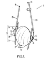
- the present invention relates to a lens holder 1 for holding an optical lens 2 during coating, comprising holding means 3 for holding the optical lens, and supporting means for operating the holding means (not represented).
- Said holding means comprise a first 3a and a second arm 3b facing each other and movable toward and away from one another, each arm being connected on one end 4 to the supporting means, and on the other end 5, through connecting means 6, to accommodating means 7 facing each other, the connecting means being such that each accommodating means rotates on pivot 12.
- the accommodating means 7 comprise a first end portion 7a, a second end portion 7c, and an intermediate portion 7b.
- the intermediate portion 7b of each accommodating means is arranged to be in continuous contact with the edge of the lens when holding the lens.
- each accommodating means 7 may pivot relative to the arm.
- both first end 7a and second end portions 7c of the accommodating means of the lens holder of the invention are arranged to be out of contact with the edge of the lens.
- the first end portion 7a is profiled to decrease the perturbations of the air/liquid interface (so-called wave phenomenon) of the coating bath and/or to break the surface of the coating (e.g. varnish) bath before the removing of the lens holder.
- the first end portion is tapered or conic.
- the second end portion 7c of the accommodating means of the lens holder of the invention is profiled to optimize drainage of the coating excess and to avoid the formation of bubbles or films when the lens is removed from the tank.
- the second end portion is also tapered or conic.
- 7a and 7c portions have the same profile.
- the lens holder of the invention further may comprise a gutter 11 positioned under the lens, and being in contact with the edge of the lens.
- At least the intermediate portion 7b of the accommodating means 7 of the lens holder of the invention includes malleable material at the contact area with the edge of the lens.
- This material is preferably selected from the group comprising elastomer plastics such as for example polyurethane, polyisoprene, polybutadiene, polychloroprene, silicone, ethylene propylene or polyacrylic. More specifically, the malleable material is polyurethane resin having a hardness from 60 to 70 shores.
- At least the intermediate portion 7b of the accommodating means 7 of the lens holder of the invention includes thermoplastic, e.g. SantopreneTM commercialized by ExxonMobil Chemical.
- the accommodating means 7 are preferably convex across their width 8, i.e. on the side in contact with the edge of the lens, for a still better adaptation to the design of the lens.
- the continuous contact area 10 between the intermediate portion 7b of the accommodating means and the edge 9 of the lens does not exceed the half of the lens circumference. Moreover, the convex side 8 of the intermediate portion 7b of the accommodating means is in contact with the edge 9 of the lens through a continuous contact area 10. This area 10 is preferably reduced to a minimum, more preferably to less than the width of the edge 9 of the lens.
Landscapes
- Engineering & Computer Science (AREA)
- Health & Medical Sciences (AREA)
- Manufacturing & Machinery (AREA)
- Ophthalmology & Optometry (AREA)
- Mechanical Engineering (AREA)
- Coating Apparatus (AREA)
- Eyeglasses (AREA)
- Grinding And Polishing Of Tertiary Curved Surfaces And Surfaces With Complex Shapes (AREA)
- Mounting And Adjusting Of Optical Elements (AREA)
- Surface Treatment Of Optical Elements (AREA)
Abstract
Lens holder (1) for holding an optical lens (2) during dip coating, which comprises:
- holding means (3) for holding the optical lens, and
- supporting means for operating the holding means,
said holding means (3) comprising a first arm (3a) and a second arm (3b) facing each other and movable toward and away from one another, each arm being connected on one part (4) to the supporting means, and on the other part (5), through connecting means (6), to accommodating means (7) facing each other, the connecting means (6) being such that each accommodating means (7) is movable with at least one degree of freedom.
Description
- The present invention relates to an optical lens holder, for holding optical lenses during the manufacturing process, especially during dip coating or vaporization manufacturing process steps. The lens holder according to the invention aims at preventing damages to optical lenses and/or to the coating applied on said lens, such as for example sags and halos.
- Treating an optical lens often involves applying at least one layer of a coating material on one or both sides of a lens. It is a requirement, for the optical quality of the lens being treated, that the coating is applied uniformly. During the dip coating process, the lens needs to be handled during its total or partial immersion into a tank containing a coating material, and then to be removed from the tank, and drained. During a vaporization process, the lens still needs to be handled.
- Various lens holders are described in the prior art; they involve different means for handling the lenses during the manufacture process. Some patents relate to ring-shaped base lens holders combined with three attachment points for retaining the lens in 3 points at its edge, see for example
US 6,473,247 orUS2004/0036989 : both lens holders include 2 means fixed to the base and a third means, which is mobile and adjustable to the diameter of the lens. Other patents, such as for exampleUS 5,325,812 , describe a spring clasp for clamping the lens, or as described inWO 2005/075108 a ring comprising a hoop for encircling and clipping the edge of a lens, forming an arc of more than 180 degrees. Another lens holder is described inUS2005/0208212 and comprises a supporting means and a first and a second arm defining a lens holder general plane, the arms being mounted on the supporting means through their first end portions and the second end portions of each arm comprising an optical lens accommodating means, said lens accommodating means facing each other, whereby an optical lens can be maintained within the accommodating means of the first and second arms through at least one, preferably one or two contact points between the lens periphery and each of the first and second lens accommodating means. - In addition to the prior art holders, there is still a need to provide a device avoiding the production of defects on lens, leading to a reduction of the optical properties of the lenses, such as the presence of a drop at the top of the lens, or sags and halos at the contact points between the holder and the lens.
- This invention aims at providing a device enabling to get a satisfactory spreading quality of coatings during a coating process.
- The present invention especially focuses on an optical lens holder which reduces, preferably avoids, the apparition of defects around the contact points of the optical lens with the holder.
- In order to reduce or avoid the appearance of such defects during a coating manufacturing step, a limitation of the surface of contact points between the lens and the holder, may be of importance. However, having a sufficient surface of contact for ensuring a satisfactory grip of the lens, is also a requirement.
- In other words, the technical problem of the invention is to provide an optical lens holder that leads to a uniform spreading of coating on the surface of the lenses and avoids the presence of coating defects such as clip marks, halos and sags.
- Thus, the present invention relates to a lens holder for holding an optical lens during a coating manufacturing step, which comprises
- holding means for holding the optical lens, and
- supporting means for operating the holding means,
- In an embodiment of the invention, the first and the second arm facing each other and movable toward and away from one another, are such that: first arm is connected to the supporting means in a static manner, such as for example through welding means, and second arm is connected to the supporting means in a dynamic manner, such as for example through an elastic articulation means, a spring means, or any suitable means, so that both arms together form a pliers able to retain the lens between the accommodating means.
- In another embodiment first and second arms are pivotally joined at a pivot to form a pliers.
- According to an embodiment, each arm is connected on a first part, which is one end of the arm, to the supporting means, and on a second part, which is the other end of the arm, to the connecting means. By part is meant any segment or portion of the arm, including the ends.
- In one embodiment, the connecting means of the lens holder of the invention are such that each accommodating means may pivot or rotate relative to the arm.
- In another embodiment, either first end portion, or second end portion, or both first end and second end portions of the accommodating means of the lens holder of the invention are arranged to be out of contact with the edge of the lens.
- Advantageously, the first end portion of the accommodating means of the lens holder of the invention may be designed to decrease the perturbations of the air/liquid interface of the coating bath.
- Preferably, the second end portion of the accommodating means of the lens holder of the invention may be designed to optimize drainage of the coating excess.
- In another embodiment, the continuous contact area between the intermediate portion of the accommodating means and the edge of the lens does not exceed the half of the lens circumference. Advantageously, in still another embodiment, the continuous contact area between the intermediate portion of the accommodating means and the edge of the lens does not exceed the third of the lens circumference.
- According to an embodiment, the lens holder of the invention further comprises a gutter positioned under the lens, which in contact with the edge of the lens, preferably at the lower point of the lens.
- In still another embodiment, at least the intermediate portion of the accommodating means of the lens holder of the invention includes malleable material at the contact area with the edge of the lens.
- In a specific embodiment this malleable material is elastomer selected from the group comprising polyurethane, polyisoprene, polybutadiene, polychloroprene, silicone, ethylene propylene or polyacrylic.
- Advantageously, the malleable material is polyurethane resin having a hardness from 60 to 70 shores.
- As described above, the invention relates to the field of the coating of lenses. Particularly the invention relates to the varnishing of lenses by dip coating or vaporization.
- Various coatings are applied on optical lenses, such as for example, but not exclusively:
- anti-reflective coating which help eliminate reflections and, consequentially, reduce the fatigue and/or stress users may experience while driving at night or working in front of a computer;
- mirror coating, which give the lens a shiny, mirror-like look and tend to reflect harsh light rays emitted from surfaces such as snow and water;
- hard coating which give abrasion-resistant properties;
- anti-smudge coating to protect the underlying coating or bulk lens material from the accumulation of such dirt or grime on the lens surface and facilitate the cleaning of the lens;
- It is also known to use dip coating or vaporization for tinting ophthalmic lens or to apply interference layers on the surface of the lenses.
- Fig.1 represents a general front view of the lens holder in use (holding a lens).
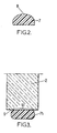
- Fig.2 represents a cross-section of an accommodating means.
- Fig.3 is a cross-section showing the contact area between the edge of the lens and an accommodating means.
- The following detailed description is of the best presently contemplated modes of carrying out the invention. This description is not to be taken in a limiting sense, but is made merely for the purpose of illustrating general principles of embodiments of the invention.
- As shown in Fig.1, the present invention relates to a
lens holder 1 for holding anoptical lens 2 during coating, comprising holding means 3 for holding the optical lens, and supporting means for operating the holding means (not represented). Said holding means comprise a first 3a and a second arm 3b facing each other and movable toward and away from one another, each arm being connected on one end 4 to the supporting means, and on theother end 5, through connectingmeans 6, to accommodating means 7 facing each other, the connecting means being such that each accommodating means rotates onpivot 12. The accommodating means 7 comprise a first end portion 7a, asecond end portion 7c, and anintermediate portion 7b. Theintermediate portion 7b of each accommodating means is arranged to be in continuous contact with the edge of the lens when holding the lens. - The specific geometry of the connecting means 6 of the lens holder of the invention is such that each accommodating means 7 may pivot relative to the arm.
- In the embodiment shown on Fig. 1, both first end 7a and
second end portions 7c of the accommodating means of the lens holder of the invention are arranged to be out of contact with the edge of the lens. The first end portion 7a is profiled to decrease the perturbations of the air/liquid interface (so-called wave phenomenon) of the coating bath and/or to break the surface of the coating (e.g. varnish) bath before the removing of the lens holder. For example, the first end portion is tapered or conic. Thesecond end portion 7c of the accommodating means of the lens holder of the invention is profiled to optimize drainage of the coating excess and to avoid the formation of bubbles or films when the lens is removed from the tank. According to an embodiment, the second end portion is also tapered or conic. In a preferred embodiment, 7a and 7c portions have the same profile. - The lens holder of the invention further may comprise a
gutter 11 positioned under the lens, and being in contact with the edge of the lens. - In a preferred embodiment of the invention, at least the
intermediate portion 7b of the accommodating means 7 of the lens holder of the invention includes malleable material at the contact area with the edge of the lens. This material is preferably selected from the group comprising elastomer plastics such as for example polyurethane, polyisoprene, polybutadiene, polychloroprene, silicone, ethylene propylene or polyacrylic. More specifically, the malleable material is polyurethane resin having a hardness from 60 to 70 shores. - Optionally, at least the
intermediate portion 7b of the accommodating means 7 of the lens holder of the invention includes thermoplastic, e.g. Santoprene™ commercialized by ExxonMobil Chemical. - As shown in Fig. 2, the
accommodating means 7 are preferably convex across their width 8, i.e. on the side in contact with the edge of the lens, for a still better adaptation to the design of the lens. - As shown in Fig.3, the continuous contact area 10 between the
intermediate portion 7b of the accommodating means and the edge 9 of the lens does not exceed the half of the lens circumference. Moreover, the convex side 8 of theintermediate portion 7b of the accommodating means is in contact with the edge 9 of the lens through a continuous contact area 10. This area 10 is preferably reduced to a minimum, more preferably to less than the width of the edge 9 of the lens.
wherein each accommodating means comprises a first end portion, a second end portion, and an intermediate portion,
the intermediate portion of each accommodating means being arranged to be in continuous contact with the edge of the lens when holding the lens.
Claims (10)
- A lens holder (1) for holding an optical lens (2) during dip coating, which comprises:- holding means (3) for holding the optical lens, and- supporting means for operating the holding means,said holding means (3) comprising a first arm (3a) and a second arm (3b) facing each other and movable toward and away from one another, each arm being connected on a first part (4) to the supporting means, and on a second part (5), through connecting means (6), to accommodating means (7) facing each other, the connecting means (6) being such that each accommodating means (7) is movable with at least one degree of freedom,
wherein each accommodating means (7) comprise a first end portion (7a), a second end portion (7c), and an intermediate portion (7b),
the intermediate portion (7b) of each accommodating means (7) being arranged to be in continuous contact (10) with the edge (9) of the lens when holding the lens. - The lens holder according to Claim 1, wherein the connecting means (6) are such that each accommodating means pivots relative to the arm.
- The lens holder according to Claim 1 or 2, wherein either first end portion (7a), or second end portion (7c), or both first end and second end portions are arranged to be out of contact with the edge of the lens.
- The lens holder according to claim 1 to 3, wherein the first end portion (7a) of the accommodating means is designed to decrease the perturbations of the air/liquid interface of the coating bath.
- The lens holder according to any one of claims 1 to 4, wherein the second end portion (7c) of the accommodating means is designed to optimize drainage of the coating excess.
- The lens holder according to any one of claims 1 to 5, wherein the continuous contact area (10) does not exceed the half of the lens circumference.
- The lens holder according to- any one of -claims 1 to 6, further comprising a gutter (11) positioned under the lens, and being in contact with the edge of the lens.
- The lens holder according to any one of claims 1 to 7, wherein at least the intermediate portion (7b) of the accommodating means include malleable material at the contact area with the edge of the lens.
- An optical lens holder according to any one of claims 1 to 8, wherein the malleable material is elastomer selected from the group comprising polyurethane, polyisoprene, polybutadiene, polychloroprene, silicone, ethylene propylene or polyacrylic; or is thermoplastic.
- The lens holder according to any one of claims 1 to 9, wherein the malleable material is polyurethane resin having a hardness from 60 to 70 shores.
Priority Applications (6)
| Application Number | Priority Date | Filing Date | Title |
|---|---|---|---|
| EP06291625A EP1914579A1 (en) | 2006-10-18 | 2006-10-18 | Optical lens holder for holding lenses during manufacturing process |
| AT07821051T ATE459892T1 (en) | 2006-10-18 | 2007-10-09 | OPTICAL LENS HOLDER FOR HOLDING LENSES DURING A MANUFACTURING PROCESS |
| US12/446,328 US20100171253A1 (en) | 2006-10-18 | 2007-10-09 | Optical lens holder for holding lenses during manufacturing process |
| DE602007005163T DE602007005163D1 (en) | 2006-10-18 | 2007-10-09 | OPTICAL LENS HOLDER FOR HOLDING LENSES DURING A MANUFACTURING PROCESS |
| PCT/EP2007/060680 WO2008046761A1 (en) | 2006-10-18 | 2007-10-09 | Optical lens holder for holding lenses during manufacturing process |
| EP07821051A EP2082277B1 (en) | 2006-10-18 | 2007-10-09 | Optical lens holder for holding lenses during manufacturing process |
Applications Claiming Priority (1)
| Application Number | Priority Date | Filing Date | Title |
|---|---|---|---|
| EP06291625A EP1914579A1 (en) | 2006-10-18 | 2006-10-18 | Optical lens holder for holding lenses during manufacturing process |
Publications (1)
| Publication Number | Publication Date |
|---|---|
| EP1914579A1 true EP1914579A1 (en) | 2008-04-23 |
Family
ID=38229141
Family Applications (2)
| Application Number | Title | Priority Date | Filing Date |
|---|---|---|---|
| EP06291625A Withdrawn EP1914579A1 (en) | 2006-10-18 | 2006-10-18 | Optical lens holder for holding lenses during manufacturing process |
| EP07821051A Not-in-force EP2082277B1 (en) | 2006-10-18 | 2007-10-09 | Optical lens holder for holding lenses during manufacturing process |
Family Applications After (1)
| Application Number | Title | Priority Date | Filing Date |
|---|---|---|---|
| EP07821051A Not-in-force EP2082277B1 (en) | 2006-10-18 | 2007-10-09 | Optical lens holder for holding lenses during manufacturing process |
Country Status (5)
| Country | Link |
|---|---|
| US (1) | US20100171253A1 (en) |
| EP (2) | EP1914579A1 (en) |
| AT (1) | ATE459892T1 (en) |
| DE (1) | DE602007005163D1 (en) |
| WO (1) | WO2008046761A1 (en) |
Cited By (1)
| Publication number | Priority date | Publication date | Assignee | Title |
|---|---|---|---|---|
| WO2018224202A1 (en) * | 2017-06-08 | 2018-12-13 | Rodenstock Gmbh | Lens holder for dip coating |
Families Citing this family (6)
| Publication number | Priority date | Publication date | Assignee | Title |
|---|---|---|---|---|
| ES2770798T3 (en) | 2008-06-04 | 2020-07-03 | Gore & Ass | Introductory sheath valve assembly for medical procedures |
| US9446428B2 (en) * | 2010-12-16 | 2016-09-20 | Essilor International (Compagnie Generale D'optique) | Method of dip-coating a segmented multifocal lens |
| CN102789034B (en) * | 2011-05-18 | 2016-06-29 | Hoya株式会社 | Lens maintenance support and lens manufacturing method |
| JP2014006322A (en) * | 2012-06-22 | 2014-01-16 | Tokuyama Corp | Lens holding member for dip coating |
| TWI503590B (en) * | 2014-06-27 | 2015-10-11 | Qisda Corp | Fixing mechanism for an optical component |
| DE102017003224A1 (en) * | 2016-09-06 | 2018-03-08 | Schneider Gmbh & Co. Kg | Arrangement and method for holding an optical workpiece and optical workpiece and glasses |
Citations (4)
| Publication number | Priority date | Publication date | Assignee | Title |
|---|---|---|---|---|
| GB2159541A (en) * | 1984-05-30 | 1985-12-04 | Balzers Hochvakuum | A multiple holding device for substrates |
| EP0483034A2 (en) * | 1990-10-24 | 1992-04-29 | MACI OPTIC Sarl | Supporting device, especially for optical glasses |
| KR100468236B1 (en) * | 2004-06-10 | 2005-01-26 | 김용길 | Hard pincher |
| EP1547696A1 (en) * | 2002-08-06 | 2005-06-29 | Seiko Epson Corporation | Lens holding jig |
Family Cites Families (7)
| Publication number | Priority date | Publication date | Assignee | Title |
|---|---|---|---|---|
| FR2672834B1 (en) * | 1991-02-18 | 1993-05-21 | Essilor Int | TIGHTENING AND GRIPPING BODY. |
| JP2001512383A (en) * | 1997-02-20 | 2001-08-21 | テクノロジー リソース インターナショナル コーポレイション | Gasket for lens formation |
| FR2783055B1 (en) | 1998-09-04 | 2000-11-24 | Essilor Int | SUPPORT FOR OPTICAL LENS, AND METHOD FOR IMPLEMENTING SAME |
| FR2839788B1 (en) | 2002-05-14 | 2004-11-05 | Essilor Int | INDIVIDUAL OPTICAL LENS SUPPORT |
| FR2865043B1 (en) | 2004-01-08 | 2006-03-10 | Essilor Int | RING FOR GRIPPING AN OPTICAL LENS FOR TREATMENT THROUGH |
| US7727581B2 (en) | 2004-03-17 | 2010-06-01 | Essilor International Compagnie Generale D' Optique | Process for applying a coating on an optical lens face and implementation system |
| JP4762984B2 (en) * | 2005-06-07 | 2011-08-31 | 株式会社トクヤマ | Method for producing plastic lens having coating layer and lens holding base |
-
2006
- 2006-10-18 EP EP06291625A patent/EP1914579A1/en not_active Withdrawn
-
2007
- 2007-10-09 DE DE602007005163T patent/DE602007005163D1/en active Active
- 2007-10-09 US US12/446,328 patent/US20100171253A1/en not_active Abandoned
- 2007-10-09 EP EP07821051A patent/EP2082277B1/en not_active Not-in-force
- 2007-10-09 WO PCT/EP2007/060680 patent/WO2008046761A1/en not_active Ceased
- 2007-10-09 AT AT07821051T patent/ATE459892T1/en not_active IP Right Cessation
Patent Citations (4)
| Publication number | Priority date | Publication date | Assignee | Title |
|---|---|---|---|---|
| GB2159541A (en) * | 1984-05-30 | 1985-12-04 | Balzers Hochvakuum | A multiple holding device for substrates |
| EP0483034A2 (en) * | 1990-10-24 | 1992-04-29 | MACI OPTIC Sarl | Supporting device, especially for optical glasses |
| EP1547696A1 (en) * | 2002-08-06 | 2005-06-29 | Seiko Epson Corporation | Lens holding jig |
| KR100468236B1 (en) * | 2004-06-10 | 2005-01-26 | 김용길 | Hard pincher |
Cited By (2)
| Publication number | Priority date | Publication date | Assignee | Title |
|---|---|---|---|---|
| WO2018224202A1 (en) * | 2017-06-08 | 2018-12-13 | Rodenstock Gmbh | Lens holder for dip coating |
| US11493724B2 (en) | 2017-06-08 | 2022-11-08 | Rodenstock Gmbh | Lens holder for dip coating |
Also Published As
| Publication number | Publication date |
|---|---|
| EP2082277A1 (en) | 2009-07-29 |
| US20100171253A1 (en) | 2010-07-08 |
| EP2082277B1 (en) | 2010-03-03 |
| ATE459892T1 (en) | 2010-03-15 |
| WO2008046761A1 (en) | 2008-04-24 |
| DE602007005163D1 (en) | 2010-04-15 |
Similar Documents
| Publication | Publication Date | Title |
|---|---|---|
| EP2082277B1 (en) | Optical lens holder for holding lenses during manufacturing process | |
| US10737371B2 (en) | Sprinkler wrench protective cover | |
| US8556248B2 (en) | Lens holders for use in lens coating processes | |
| WO2005084943A3 (en) | Substrate, such as a glass substrate, with a hydrophobic surface and improved durability of hydrophobic properties | |
| WO2009042072A3 (en) | Polishing composition and method utilizing abrasive particles treated with an aminosilane | |
| CA2529321A1 (en) | Process for replacing an initial outermost coating layer of a coated optical lens by or depositing thereon a different coating layer | |
| EP1461377A2 (en) | Treatment of polarizing films for improved adhesion to subsequent optical coatings | |
| WO2006113266A3 (en) | Coated filter media | |
| EP3479956A1 (en) | Method for manufacturing optical elements according to a prescription | |
| WO2016055866A1 (en) | Methods and apparatus for cleaning blocked ophthalmic lenses | |
| ATE490053T1 (en) | METHOD FOR RELEASING LENSES | |
| US12583008B2 (en) | Holding jig, optical element coating method, and optical lens manufacturing method | |
| US20160091928A1 (en) | Glass touch screen protector | |
| IL177865A0 (en) | Coating for metal surfaces, process for the producing it and use thereof as a self-cleaning protective coat, especially for auto rims | |
| CN1675000A (en) | Lens Holder | |
| US8770565B2 (en) | Jig for surface treatment | |
| JP6270787B2 (en) | Treatment liquid applicator | |
| AU2003281685A1 (en) | Surface-roughened resin film, metal sheet coated with surface-roughened resin film, process for producing metal sheet coated with surface-roughened resin film, and metal can having surface coated with surface-roughened resin film and process for producing the same | |
| KR101692960B1 (en) | Scratch Repair sticker and manufacturing method | |
| WO2006088737A3 (en) | Semiconductor cleaning | |
| EP1703993B1 (en) | Method for immersion processing of optical elements | |
| EP2811334A1 (en) | Manufacturing method of eyeglass lens and lens holder | |
| JP3451647B2 (en) | Surface treatment equipment | |
| US20190247982A1 (en) | Automotive Detail Block | |
| CN112975649A (en) | Glass lens edge grinding process |
Legal Events
| Date | Code | Title | Description |
|---|---|---|---|
| PUAI | Public reference made under article 153(3) epc to a published international application that has entered the european phase |
Free format text: ORIGINAL CODE: 0009012 |
|
| AK | Designated contracting states |
Kind code of ref document: A1 Designated state(s): AT BE BG CH CY CZ DE DK EE ES FI FR GB GR HU IE IS IT LI LT LU LV MC NL PL PT RO SE SI SK TR |
|
| AX | Request for extension of the european patent |
Extension state: AL BA HR MK RS |
|
| AKX | Designation fees paid | ||
| REG | Reference to a national code |
Ref country code: DE Ref legal event code: 8566 |
|
| STAA | Information on the status of an ep patent application or granted ep patent |
Free format text: STATUS: THE APPLICATION IS DEEMED TO BE WITHDRAWN |
|
| 18D | Application deemed to be withdrawn |
Effective date: 20081024 |