EP1914169A1 - A unit and a method for feeding labels in a packer machine for tobacco products - Google Patents
A unit and a method for feeding labels in a packer machine for tobacco products Download PDFInfo
- Publication number
- EP1914169A1 EP1914169A1 EP07118335A EP07118335A EP1914169A1 EP 1914169 A1 EP1914169 A1 EP 1914169A1 EP 07118335 A EP07118335 A EP 07118335A EP 07118335 A EP07118335 A EP 07118335A EP 1914169 A1 EP1914169 A1 EP 1914169A1
- Authority
- EP
- European Patent Office
- Prior art keywords
- labels
- station
- stack
- take
- unit
- Prior art date
- Legal status (The legal status is an assumption and is not a legal conclusion. Google has not performed a legal analysis and makes no representation as to the accuracy of the status listed.)
- Granted
Links
Images


Classifications
-
- B—PERFORMING OPERATIONS; TRANSPORTING
- B65—CONVEYING; PACKING; STORING; HANDLING THIN OR FILAMENTARY MATERIAL
- B65C—LABELLING OR TAGGING MACHINES, APPARATUS, OR PROCESSES
- B65C9/00—Details of labelling machines or apparatus
- B65C9/08—Label feeding
- B65C9/12—Removing separate labels from stacks
- B65C9/14—Removing separate labels from stacks by vacuum
-
- B—PERFORMING OPERATIONS; TRANSPORTING
- B65—CONVEYING; PACKING; STORING; HANDLING THIN OR FILAMENTARY MATERIAL
- B65H—HANDLING THIN OR FILAMENTARY MATERIAL, e.g. SHEETS, WEBS, CABLES
- B65H3/00—Separating articles from piles
- B65H3/08—Separating articles from piles using pneumatic force
- B65H3/0808—Suction grippers
- B65H3/085—Suction grippers separating from the bottom of pile
-
- B—PERFORMING OPERATIONS; TRANSPORTING
- B65—CONVEYING; PACKING; STORING; HANDLING THIN OR FILAMENTARY MATERIAL
- B65H—HANDLING THIN OR FILAMENTARY MATERIAL, e.g. SHEETS, WEBS, CABLES
- B65H3/00—Separating articles from piles
- B65H3/34—Article-retaining devices controlling the release of the articles to the separators
-
- B—PERFORMING OPERATIONS; TRANSPORTING
- B65—CONVEYING; PACKING; STORING; HANDLING THIN OR FILAMENTARY MATERIAL
- B65H—HANDLING THIN OR FILAMENTARY MATERIAL, e.g. SHEETS, WEBS, CABLES
- B65H3/00—Separating articles from piles
- B65H3/42—Separating articles from piles by two or more separators mounted for movement with, or relative to, rotary or oscillating bodies
-
- B—PERFORMING OPERATIONS; TRANSPORTING
- B65—CONVEYING; PACKING; STORING; HANDLING THIN OR FILAMENTARY MATERIAL
- B65H—HANDLING THIN OR FILAMENTARY MATERIAL, e.g. SHEETS, WEBS, CABLES
- B65H2513/00—Dynamic entities; Timing aspects
- B65H2513/10—Speed
-
- B—PERFORMING OPERATIONS; TRANSPORTING
- B65—CONVEYING; PACKING; STORING; HANDLING THIN OR FILAMENTARY MATERIAL
- B65H—HANDLING THIN OR FILAMENTARY MATERIAL, e.g. SHEETS, WEBS, CABLES
- B65H2515/00—Physical entities not provided for in groups B65H2511/00 or B65H2513/00
- B65H2515/30—Forces; Stresses
- B65H2515/34—Pressure, e.g. fluid pressure
-
- B—PERFORMING OPERATIONS; TRANSPORTING
- B65—CONVEYING; PACKING; STORING; HANDLING THIN OR FILAMENTARY MATERIAL
- B65H—HANDLING THIN OR FILAMENTARY MATERIAL, e.g. SHEETS, WEBS, CABLES
- B65H2701/00—Handled material; Storage means
- B65H2701/10—Handled articles or webs
- B65H2701/19—Specific article or web
- B65H2701/192—Labels
-
- B—PERFORMING OPERATIONS; TRANSPORTING
- B65—CONVEYING; PACKING; STORING; HANDLING THIN OR FILAMENTARY MATERIAL
- B65H—HANDLING THIN OR FILAMENTARY MATERIAL, e.g. SHEETS, WEBS, CABLES
- B65H2801/00—Application field
- B65H2801/54—Cigarette making
Definitions
- the present invention relates to a label feeder unit and to a method of feeding labels in a packer machine for tobacco products.
- the invention finds application in the art field of devices for dispensing revenue stamps, coupons or tamper-evident seals, and of units for picking up and transferring such items to equipment by which they are affixed or applied to packets containing tobacco products.
- the labels are fed to a pick-up and transfer unit by which they will be gummed and then affixed to the packets.
- the labels are arranged in one or more ordered stacks, each comprising a plurality of labels placed one on top of another.
- the labels therefore combine to form a single compact block.
- Machines of prior art type for applying labels to packets of tobacco products are equipped with arms supporting the stack of labels, and serving also to establish a feed path along which the labels are advanced.
- the stack is subjected to a pushing force, directed toward the pick-up unit, so that the labels remain compacted together.
- the pressure applied thus to the stack of labels can be generated by simple force of gravity, in the case of a vertical machine, or by push rods in the case of a horizontal machine; at all events, a force is directed through the stack, impinging ultimately on restraints afforded by the ends of the arms aforementioned and facing the pick-up unit.
- the function of the restraints is to hold the labels in a predetermined position when taken up from the stack, in such a way as to facilitate the step by which the single labels are picked up.
- the force applied to the compacted labels induces an elastic deformation of the stack, in measure proportional to the number of labels making up the stack at any given moment.
- the object of the present invention is to provide a unit and a method for feeding labels in a packer machine for tobacco products, such as will be unaffected by the drawbacks mentioned above.
- One object of the invention is to provide a unit and a method for feeding labels in a packer machine for tobacco products, designed to allow a correct and systematic release of the single labels from the dispensing device to the pick-up and transfer unit.
- a further object of the invention is to provide a unit and a method for feeding labels in a packer machine for tobacco products, by which labels can be transferred correctly in high numbers per unit of time.
- numeral 1 denotes a label feeder unit, in its entirety, forming part of a packer machine for tobacco products.
- the single labels are denoted 100 in the drawings.
- 'label' in the context of the present invention, can signify a revenue stamp, a coupon, a tamper-evident seal or other such slip typically of paper material, applicable for whatever purpose to packets containing tobacco products.
- the unit 1 is associated operationally with pick-up and transfer means 2 by which labels 100 are conveyed singly and in ordered succession to user means denoted 101, schematized in figure 3 as a rotating drum 3.
- the feeder unit 1 comprises means 3 by which to support a plurality of labels 100 placed one on top of another to form a stack 102.
- the labels 100 are supplied to the unit 1 through the agency of a conventional mechanism not shown in the drawings, such as will direct a flow of the labels 100 to a first end of the stack 102.
- the support means 3 comprise a plate 4 anchorable to a fixed structure employing means of conventional type (not illustrated), and two guide rails 5 stably associated with the plates 4.
- the two guide rails 5 extend parallel one with another and function as respective flat walls 6.
- the two walls 6 and the portion of the plate 4 delimited by the guide rails 5 combine to create a channel 7 accommodating the stack 102 of labels 100, which presents an infeed end 7a facing the aforementioned supply mechanism, and an outfeed end 7b.
- the width of the channel 7, that is to say the distance between the two walls 6, corresponds to one of the dimensions of a single label 100, so that the stack of labels can be housed in the channel 7 substantially to an exact fit.
- the guide rails 5 might be capable of movement toward and away from one another in such a way as to adapt the width of the channel 7 to the size of label 100 in use.
- the labels 100 are arranged in the channel 7 such that each occupies a respective plane substantially perpendicular to the plate 4.
- the stack 102 is caused to pass continuously along the channel 7, and in particular along a direction coinciding with the longitudinal axis of the stack 102.
- the unit 1 comprises pushing means of conventional embodiment (not illustrated) located at the infeed 7a of the channel 7, such as will apply a pushing force to the stack 102, directed along the axis A of the selfsame stack 102 toward the outfeed end 7b of the channel 7.
- a station 8 Located beyond the outfeed 7d of the channel 7 is a station 8 at which the labels 100 are taken up by the pick-up and transfer means 2 in readiness for their release to the user means 101.
- the unit 1 further comprises transfer means 9 located between the outfeed 7b of the channel 7 and the take-up station 8, by which labels 100 are received in sequence one at a time from the bottom of the stack 102 and transferred to the take-up station 8.
- the take-up station 8 is adjustable for position relative both to the outfeed 7b of the channel 7 and to the transfer means 9, according to the pressure exerted on the selfsame station 8 by the succession of labels 100 in the process of being transferred.
- the unit 1 further comprises feedback control means 10 acting on the transfer means 9 in such a way as to ensure that the pressure exerted by the succession of labels 10 on the take-up station 8 is kept within prescribed values.
- the pressure that registers through the labels 100 occupying the take-up station remains substantially constant, favouring a correct release of the labels 100 to the pick-up and transfer means 2.
- the labels 100 will be taken up correctly, one by one, avoiding the release of two or more single labels at a time, when the pressure acting on the labels at the outfeed end of the stack, and therefore at the take-up station 8, is maintained substantially constant and above a predetermined minimum threshold.
- the action of the feedback control means 10 on the transfer means 9 serves also to ensure that the distance between the outfeed end 7b of the channel 7 and the take-up station 8 is kept likewise within prescribed values, thereby maximizing the efficiency of the pick-up and transfer means 2.
- control over the distance between the take-up station 8 and the outfeed end 7b of the channel 7 is a function, indeed a consequence, of the control maintained over the pressure exerted by the labels 100 on the take-up station 8 given that it is this same pressure, as mentioned previously, that causes the take-up station 8 to move away from or toward the outfeed end 7b of the channel 7.
- the transfer means 9 also function as detent means by which the feed motion of the stack 102 is checked at the outfeed end 7b of the channel 7.
- the stack 102 retains its elasticity, and the pressure exerted on the take-up station 8 is not influenced by the number of labels 100 making up the stack, but dependent only on the number of labels 100 released per unit of time by the transfer means 9 to the take-up station 8.
- the take-up station 8 comprises at least two abutment members denoted 11, each incorporating a restraint 12 presented by one end of a rod-like element 13.
- the restraints 12 of the two abutment members 11 are mutually opposed and positioned to interact with the opposite edges of a label 103 at the moment of release, in such a way that the label is steadied and presented to the pick-up and transfer means 2.
- the abutment members 11 are slidable independently of one another along an axis parallel to the axis A of the stack 102 of labels in response to the pressure exerted by the advancing labels 100 on the restraints 12.
- the rod-like elements 13 are slidable in grooves 15 afforded by the guide rails 5 of the channel 7, their translational motion guided by link rods 15 connecting the rod-like element 13 to the plate 4.
- the feedback control means 10 comprise at least one traction element 16 schematized as a spring in figures 1 and 2, which indicate two such springs, each operating between an abutment member 11 and a guide rail 5.
- each of the traction elements 16 is connected at one end to one rod-like element 13 and at the opposite end to a portion of the guide rail 5 located upstream of the portion presenting the groove 14 in which the rod-like element 13 is slidable.
- the traction elements 16 exert a predetermined force on the abutment members 11, generated in a direction opposite to the force exerted by the labels 100 on the restraints 12, in such a way that motion will be induced in the abutment members 11 when the pushing force on the restraints 12 is greater or less than the force exerted by the traction elements 16.
- the position sensors 17 are located internally of the guide rails 5 so as to measure the displacement of the rod-like elements 13; in practice, however, any other type of sensor might be used equally well to measure the displacement of the abutment members 11.
- the position sensors 17 will be connected to a master control unit (not illustrated) which, in possession of data indicating the force exerted on the abutment members 11 by the traction elements 16, and of data indicating the displacement of the abutment members 11, is able to compute the pressure exerted at any given moment on the restraints 12 by the labels 100 passing through the transfer means 9.
- a master control unit not illustrated
- the master control unit acts in feedback mode on the transfer means 9, raising or lowering the rate at which the labels 100 are released to the take-up station 8 according to the pressure acting on the restraints 12 at any given moment.
- the position of the restraints 12 will also be monitored continuously and kept within prescribed values.
- the transfer means 9 include a first pair of rollers 18 mounted rotatably to the plate 4, each turning on a respective axis X1 and X2 normal to the plate 4 and thus orthogonal to the axis A of the stack 102 of labels.
- rollers 18 are placed at the outfeed end 7b of the channel 7 on opposite sides of the stack 102 and set in contrarotation by drive means, not shown in the drawings, so as to engage and transfer the labels from the stack 102 to the take-up station 8.
- the revolving surfaces of the rollers 18 present a knurled profile 19.
- the ridges of the knurled profile 19 extend along directions parallel to the axes X1 and X2 of rotation of the rollers 18, thus lying parallel to the respective edges of the labels 100 with which they engage.
- the rollers 18 are set apart one from another by a distance less than the width of the stack 102, so as to intercept and advance the labels 100.
- rollers 18 also provide the aforementioned detent means checking the feed motion of the stack 102.
- the rollers 18 (when not in rotation, self-evidently) intercept the stack 102 and prevent the labels 100 from advancing, irrespective of the pressure exerted on the rollers 18 by the selfsame labels.
- the restraints 12 coincide with a line of mutual alignment extending parallel to and below the line joining the centres of the rollers 18.
- the master control unit corrects the misalignment by increasing or reducing the speed at which one of the two rollers 18 rotates, for a limited period, following which the labels 100 will realign and the pressure exerted on both abutment members 11 is equalized.
- a further pair of rollers could be provided, flanking the rollers 18 of the first pair, and two further abutment members operating independently of one another, flanking the two abutment members 11 already described.
- the four abutment members would interact with the four corners, or corner edges, of the labels.
- rollers 18 of the pair illustrated in the drawings combine to create a path converging along the transfer direction of the labels 100 toward the pick-up station 8, in such a way that the labels are deformed during the transfer step.
- the deformation of the transferred labels 100 is induced by bending each one relative to the plane occupied at the outfeed end 7b, thereby generating a concave face directed back toward the stack 102.
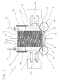
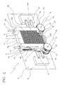
- Each deformed label 100 thus presents a bowed central portion of which the convex face is directed toward the pick-up and transfer means 2, as illustrated in the bottom part of figures 1 and 2.
- the restraints 12 are angled in such a way as to lie tangential to the bowed portion of the endmost label 103.
- the aforementioned pick-up and transfer means 2 comprise a rotary conveyor 105 shown in figure 3, rotatable about an axis denoted X3, by which the single labels 103 are received from the take-up station 8 and conveyed to the aforementioned user means 101.
- the pick-up and transfer means 2 comprise a plurality of gripping and retaining carriers 106 arranged around a peripheral surface of the rotary conveyor 105 and defining a feed path along which the successive endmost labels 103 of the stack are transported, retained by suction during the rotation of the conveyor 105.
- each gripping and retaining carrier 106 comprises a pair of suction cups 107 disposed side by side, thereby combining with the other carriers to form two rows of cups around the periphery.
- each of the suction cups 107 of each pair can be offered simultaneously to the endmost single label 103 of the stack 102, which is thereupon taken up by vacuum force.
- each of the suction cups 107 is connected by way of a duct 108 to vacuum means of conventional type, not illustrated in the drawings.
- Each carrier 106 also comprises motion-inducing means 109 that serve to guide the suction cups 107 between a plurality of pick-up positions in which the two cup rims occupy respective mutually inclined gripping planes, as illustrated in figure 4, and a release position in which the rims occupy a common plane, as illustrated in figure 5.
- the motion-inducing means 109 present a pivotable mechanism 110 supporting the suction cups 107, of which the rocking motion defines the aforementioned pick-up position and release position of the suction cups 107.
- the pivotable mechanism 110 incorporates a first arm 110a and a second arm 110b, each hinged to the peripheral surface of the rotary conveyor 105 about a respective pivot axis X4 and carrying a respective suction cup 107.
- the two arms 110a and 110b are interconnected by way of a translatable hinge 110c occupying an intermediate position between the two arms 110a and 110b, so that the selfsame arms can be contrarotated through an identical angle about the respective pivot axes X4, and the suction cups 107 made to assume the pick-up and release positions.
- the motion-inducing means 109 further comprise a push-pull rod 111 linked to the two arms 110a and 110b, which acts on the hinge 110c in such a way as to rotate the arms 110a and 110b and thus cause the suction cups 107 to shift between the two operating positions.
- the push-pull rod 111 is preferably reciprocated, capable of movement between a position retracted partly into the rotary conveyor 105, with the two arms 110a and 110b rotated in such a way as to bring the two suction cups 107 closer together, and an extended position with the two arms 110a and 110b rotated in such a manner as to spread the suction cups 107 farther apart.
- the rod 111 might be actuated electrically or pneumatically, by way of example.
- the suction cups 107 are secured to respective clevis mounts 112, each attached pivotably to the respective arm 110a and 110b and rotatable thus about a relative axis X5. Anchored pivotably in this way, the suction cups 107 are able to assume the pick-up and release positions described above.
- the release position of the suction cups 107 is assumed when the push-pull rod 111 occupies the retracted position, causing the arms 110a and 110b to rotate in such a way that the suction cups 107 are drawn together, effectively to their minimum distance one from another.
- the pressure exerted on the station can be maintained substantially constant, as also can the position of the station itself.
Landscapes
- Engineering & Computer Science (AREA)
- Mechanical Engineering (AREA)
- Labeling Devices (AREA)
- Wrapping Of Specific Fragile Articles (AREA)
- Basic Packing Technique (AREA)
Abstract
Description
- The present invention relates to a label feeder unit and to a method of feeding labels in a packer machine for tobacco products.
- In particular, the invention finds application in the art field of devices for dispensing revenue stamps, coupons or tamper-evident seals, and of units for picking up and transferring such items to equipment by which they are affixed or applied to packets containing tobacco products.
- In conventional machines for applying labels to packets containing tobacco products, the labels are fed to a pick-up and transfer unit by which they will be gummed and then affixed to the packets.
- During the step of feeding the labels to the pick-up and transfer unit, the labels are arranged in one or more ordered stacks, each comprising a plurality of labels placed one on top of another. The labels therefore combine to form a single compact block.
- Machines of prior art type for applying labels to packets of tobacco products are equipped with arms supporting the stack of labels, and serving also to establish a feed path along which the labels are advanced. The stack is subjected to a pushing force, directed toward the pick-up unit, so that the labels remain compacted together.
- The pressure applied thus to the stack of labels can be generated by simple force of gravity, in the case of a vertical machine, or by push rods in the case of a horizontal machine; at all events, a force is directed through the stack, impinging ultimately on restraints afforded by the ends of the arms aforementioned and facing the pick-up unit.
- The function of the restraints is to hold the labels in a predetermined position when taken up from the stack, in such a way as to facilitate the step by which the single labels are picked up.
- It has been found, during the operation of conventional machines, that the step of picking up the labels can be problematic.
- In effect, a degree of adhesion is created between the stacked labels, due mainly to the force applied at the top or rear of the stack to keep it compact, which works in opposition to the pick-up action.
- The extent of the adhesion aforementioned is also difficult to predict, since the force applied to the stack of labels is dependent (especially in vertical machines) on the number of labels remaining in the stack as each successive pick-up is completed.
- In addition, the force applied to the compacted labels induces an elastic deformation of the stack, in measure proportional to the number of labels making up the stack at any given moment.
- Consequently, it happens in certain circumstances that no label will be picked up, or that two or more labels are picked up at once.
- The drawback in question is betrayed particularly by label feeder units in cigarette packers of the latest generation, where labels must be taken from the stack and transferred at rates of up to a thousand per minute.
- Accordingly, the object of the present invention is to provide a unit and a method for feeding labels in a packer machine for tobacco products, such as will be unaffected by the drawbacks mentioned above.
- One object of the invention, in particular, is to provide a unit and a method for feeding labels in a packer machine for tobacco products, designed to allow a correct and systematic release of the single labels from the dispensing device to the pick-up and transfer unit.
- A further object of the invention is to provide a unit and a method for feeding labels in a packer machine for tobacco products, by which labels can be transferred correctly in high numbers per unit of time.
- The stated objects are realized in a unit and a method for feeding labels in a packer machine for tobacco products, of which the features are recited in one or more of the appended claims.
- The invention will now be described in detail, by way of example, with the aid of the accompanying drawings, in which:
- figure 1 shows a label feeder unit in a packer machine for tobacco products according to the present invention, illustrated in plan with certain parts omitted better to reveal others;
- figure 2 is a perspective view of the unit in figure 1;
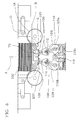
- figure 3 is a side view of the label feeder unit according to the present invention;
- figure 4 is a sectional view showing a portion of the unit as in figure 3, illustrated in a first operating position;
- figure 5 is a sectional view showing the portion of figure 4, illustrated in a second operating position and with certain parts omitted better to reveal others.
- With reference to the drawings,
numeral 1 denotes a label feeder unit, in its entirety, forming part of a packer machine for tobacco products. The single labels are denoted 100 in the drawings. - The term 'label', in the context of the present invention, can signify a revenue stamp, a coupon, a tamper-evident seal or other such slip typically of paper material, applicable for whatever purpose to packets containing tobacco products.
- As shown in figure 3, the
unit 1 is associated operationally with pick-up and transfer means 2 by whichlabels 100 are conveyed singly and in ordered succession to user means denoted 101, schematized in figure 3 as arotating drum 3. - The
feeder unit 1 comprises means 3 by which to support a plurality oflabels 100 placed one on top of another to form astack 102. - The
labels 100 are supplied to theunit 1 through the agency of a conventional mechanism not shown in the drawings, such as will direct a flow of thelabels 100 to a first end of thestack 102. - In detail, the support means 3 comprise a
plate 4 anchorable to a fixed structure employing means of conventional type (not illustrated), and twoguide rails 5 stably associated with theplates 4. - The two
guide rails 5 extend parallel one with another and function as respective flat walls 6. The two walls 6 and the portion of theplate 4 delimited by theguide rails 5 combine to create achannel 7 accommodating thestack 102 oflabels 100, which presents an infeedend 7a facing the aforementioned supply mechanism, and anoutfeed end 7b. - The width of the
channel 7, that is to say the distance between the two walls 6, corresponds to one of the dimensions of asingle label 100, so that the stack of labels can be housed in thechannel 7 substantially to an exact fit. - In an alternative embodiment of the invention (not indicated), the
guide rails 5 might be capable of movement toward and away from one another in such a way as to adapt the width of thechannel 7 to the size oflabel 100 in use. - The
labels 100 are arranged in thechannel 7 such that each occupies a respective plane substantially perpendicular to theplate 4. - With the
labels 100 subjected to a constant feed and pick-up action, thestack 102 is caused to pass continuously along thechannel 7, and in particular along a direction coinciding with the longitudinal axis of thestack 102. - To this end, the
unit 1 comprises pushing means of conventional embodiment (not illustrated) located at the infeed 7a of thechannel 7, such as will apply a pushing force to thestack 102, directed along the axis A of theselfsame stack 102 toward theoutfeed end 7b of thechannel 7. - Located beyond the outfeed 7d of the
channel 7 is astation 8 at which thelabels 100 are taken up by the pick-up and transfer means 2 in readiness for their release to the user means 101. - As illustrated in the accompanying drawings, the
unit 1 further comprises transfer means 9 located between the outfeed 7b of thechannel 7 and the take-up station 8, by whichlabels 100 are received in sequence one at a time from the bottom of thestack 102 and transferred to the take-up station 8. - The take-
up station 8 is adjustable for position relative both to the outfeed 7b of thechannel 7 and to the transfer means 9, according to the pressure exerted on theselfsame station 8 by the succession oflabels 100 in the process of being transferred. - More exactly, the greater the number of
labels 100 transferred per unit of time from theoutfeed end 7b of the channel to the take-up station 8, the greater the pressure exerted by thelabels 100 on theselfsame station 8 and consequently the greater the displacement of the station. - The
unit 1 further comprises feedback control means 10 acting on the transfer means 9 in such a way as to ensure that the pressure exerted by the succession oflabels 10 on the take-up station 8 is kept within prescribed values. - Thus, advantageously, the pressure that registers through the
labels 100 occupying the take-up station remains substantially constant, favouring a correct release of thelabels 100 to the pick-up and transfer means 2. - In effect, it has been verified by experiment that the
labels 100 will be taken up correctly, one by one, avoiding the release of two or more single labels at a time, when the pressure acting on the labels at the outfeed end of the stack, and therefore at the take-up station 8, is maintained substantially constant and above a predetermined minimum threshold. - In addition, and to advantage, the action of the feedback control means 10 on the transfer means 9 serves also to ensure that the distance between the
outfeed end 7b of thechannel 7 and the take-up station 8 is kept likewise within prescribed values, thereby maximizing the efficiency of the pick-up andtransfer means 2. - In practice, control over the distance between the take-
up station 8 and theoutfeed end 7b of thechannel 7 is a function, indeed a consequence, of the control maintained over the pressure exerted by thelabels 100 on the take-up station 8 given that it is this same pressure, as mentioned previously, that causes the take-up station 8 to move away from or toward theoutfeed end 7b of thechannel 7. - To advantage, therefore, when the pressure exerted on the take-
up station 8 is maintained within prescribed values, the distance between thissame station 8 and theoutfeed end 7b of thechannel 7 is kept likewise within prescribed values. - As discernible from figure 1, in particular, the transfer means 9 also function as detent means by which the feed motion of the
stack 102 is checked at theoutfeed end 7b of thechannel 7. - In this situation, the pressure directed from the
stack 102 toward the take-up station 8, generated by the force of the aforementioned pushing means, or of gravity in the case of avertical unit 1, will not actually be transmitted to the take-up station 8. - Accordingly, the
stack 102 retains its elasticity, and the pressure exerted on the take-up station 8 is not influenced by the number oflabels 100 making up the stack, but dependent only on the number oflabels 100 released per unit of time by the transfer means 9 to the take-up station 8. - In a preferred embodiment of the unit, the take-
up station 8 comprises at least two abutment members denoted 11, each incorporating arestraint 12 presented by one end of a rod-like element 13. - The
restraints 12 of the twoabutment members 11 are mutually opposed and positioned to interact with the opposite edges of alabel 103 at the moment of release, in such a way that the label is steadied and presented to the pick-up and transfer means 2. - The
abutment members 11 are slidable independently of one another along an axis parallel to the axis A of thestack 102 of labels in response to the pressure exerted by the advancinglabels 100 on therestraints 12. - As illustrated in figures 1 and 2, in particular, the rod-
like elements 13 are slidable ingrooves 15 afforded by theguide rails 5 of thechannel 7, their translational motion guided bylink rods 15 connecting the rod-like element 13 to theplate 4. - The feedback control means 10 comprise at least one
traction element 16 schematized as a spring in figures 1 and 2, which indicate two such springs, each operating between anabutment member 11 and aguide rail 5. - In particular, each of the
traction elements 16 is connected at one end to one rod-like element 13 and at the opposite end to a portion of theguide rail 5 located upstream of the portion presenting thegroove 14 in which the rod-like element 13 is slidable. - The
traction elements 16 exert a predetermined force on theabutment members 11, generated in a direction opposite to the force exerted by thelabels 100 on therestraints 12, in such a way that motion will be induced in theabutment members 11 when the pushing force on therestraints 12 is greater or less than the force exerted by thetraction elements 16. - The movement of the
abutment members 11 is also piloted byposition sensors 17, illustrated in figures 1 and 2, which form part of the feedback control means 10. - In the example of the accompanying drawings, the
position sensors 17 are located internally of theguide rails 5 so as to measure the displacement of the rod-like elements 13; in practice, however, any other type of sensor might be used equally well to measure the displacement of theabutment members 11. - Whatever the type adopted, the
position sensors 17 will be connected to a master control unit (not illustrated) which, in possession of data indicating the force exerted on theabutment members 11 by thetraction elements 16, and of data indicating the displacement of theabutment members 11, is able to compute the pressure exerted at any given moment on therestraints 12 by thelabels 100 passing through the transfer means 9. - Thus, the master control unit acts in feedback mode on the transfer means 9, raising or lowering the rate at which the
labels 100 are released to the take-up station 8 according to the pressure acting on therestraints 12 at any given moment. - Importantly, to reiterate, the position of the
restraints 12 will also be monitored continuously and kept within prescribed values. - In the example illustrated, the transfer means 9 include a first pair of
rollers 18 mounted rotatably to theplate 4, each turning on a respective axis X1 and X2 normal to theplate 4 and thus orthogonal to the axis A of thestack 102 of labels. - The
rollers 18 are placed at theoutfeed end 7b of thechannel 7 on opposite sides of thestack 102 and set in contrarotation by drive means, not shown in the drawings, so as to engage and transfer the labels from thestack 102 to the take-upstation 8. - With this end in view, to ensure the
labels 100 are taken up cleanly, the revolving surfaces of therollers 18 present aknurled profile 19. The ridges of theknurled profile 19 extend along directions parallel to the axes X1 and X2 of rotation of therollers 18, thus lying parallel to the respective edges of thelabels 100 with which they engage. - The
rollers 18 are set apart one from another by a distance less than the width of thestack 102, so as to intercept and advance thelabels 100. - It will be seen therefore that the
rollers 18 also provide the aforementioned detent means checking the feed motion of thestack 102. - In effect, the rollers 18 (when not in rotation, self-evidently) intercept the
stack 102 and prevent thelabels 100 from advancing, irrespective of the pressure exerted on therollers 18 by the selfsame labels. - Accordingly, the pressure exerted via the
stacked labels 100 on therollers 18 is not transmitted to theabutment members 11 of the take-upstation 8, bringing the advantages mentioned previously. - The point at which the
stack 102 of labels is intercepted by therollers 18 coincides with a halt line B extending parallel to and upstream of the line joining the centres of therollers 18, as illustrated in figures 1 and 4. - Conversely, the
restraints 12 coincide with a line of mutual alignment extending parallel to and below the line joining the centres of therollers 18. - To advantage, with the
abutment members 11 capable of movement independently of one another, as in the preferred embodiment described thus far, it becomes possible to identify and correct any transfer of thelabels 100 which, though made at the correct rate, occurs with the labels not perfectly at right angles to the axis A of thestack 102. - In this situation, the pressures impinging on the two
abutment members 11 would be dissimilar one to another, indicating that thelabels 100 entering the take-upstation 8 are skew relative to the correct transfer plane. - The master control unit corrects the misalignment by increasing or reducing the speed at which one of the two
rollers 18 rotates, for a limited period, following which thelabels 100 will realign and the pressure exerted on bothabutment members 11 is equalized. - In an alternative embodiment, not illustrated, a further pair of rollers could be provided, flanking the
rollers 18 of the first pair, and two further abutment members operating independently of one another, flanking the twoabutment members 11 already described. - The four abutment members would interact with the four corners, or corner edges, of the labels.
- With this arrangement, similarly, it will also be possible to correct a misalignment of the advancing
labels 100 relative to a plane perpendicular to the plane described previously. - In other words, adopting a solution of this type, it will be possible to verify and ensure that the
labels 100 advance exactly orthogonal to the axis A of thestack 102, or at all events aligned on any given plane. - The
rollers 18 of the pair illustrated in the drawings combine to create a path converging along the transfer direction of thelabels 100 toward the pick-upstation 8, in such a way that the labels are deformed during the transfer step. - To advantage, the deformation of the transferred labels 100 is induced by bending each one relative to the plane occupied at the
outfeed end 7b, thereby generating a concave face directed back toward thestack 102. Eachdeformed label 100 thus presents a bowed central portion of which the convex face is directed toward the pick-up and transfer means 2, as illustrated in the bottom part of figures 1 and 2. - Accordingly, the
restraints 12 are angled in such a way as to lie tangential to the bowed portion of theendmost label 103. - The aforementioned pick-up and transfer means 2 comprise a
rotary conveyor 105 shown in figure 3, rotatable about an axis denoted X3, by which thesingle labels 103 are received from the take-upstation 8 and conveyed to the aforementioned user means 101. - The pick-up and transfer means 2 comprise a plurality of gripping and retaining
carriers 106 arranged around a peripheral surface of therotary conveyor 105 and defining a feed path along which the successiveendmost labels 103 of the stack are transported, retained by suction during the rotation of theconveyor 105. - As illustrated in detail in figures 4 and 5, each gripping and retaining
carrier 106 comprises a pair ofsuction cups 107 disposed side by side, thereby combining with the other carriers to form two rows of cups around the periphery. - The suction cups 107 of each pair can be offered simultaneously to the endmost
single label 103 of thestack 102, which is thereupon taken up by vacuum force. To this end, each of thesuction cups 107 is connected by way of aduct 108 to vacuum means of conventional type, not illustrated in the drawings. - Each
carrier 106 also comprises motion-inducingmeans 109 that serve to guide thesuction cups 107 between a plurality of pick-up positions in which the two cup rims occupy respective mutually inclined gripping planes, as illustrated in figure 4, and a release position in which the rims occupy a common plane, as illustrated in figure 5. - The motion-inducing
means 109 present apivotable mechanism 110 supporting thesuction cups 107, of which the rocking motion defines the aforementioned pick-up position and release position of thesuction cups 107. - The
pivotable mechanism 110 incorporates afirst arm 110a and asecond arm 110b, each hinged to the peripheral surface of therotary conveyor 105 about a respective pivot axis X4 and carrying arespective suction cup 107. The twoarms translatable hinge 110c occupying an intermediate position between the twoarms suction cups 107 made to assume the pick-up and release positions. - The motion-inducing
means 109 further comprise a push-pull rod 111 linked to the twoarms hinge 110c in such a way as to rotate thearms suction cups 107 to shift between the two operating positions. - The push-
pull rod 111 is preferably reciprocated, capable of movement between a position retracted partly into therotary conveyor 105, with the twoarms suction cups 107 closer together, and an extended position with the twoarms suction cups 107 farther apart. Therod 111 might be actuated electrically or pneumatically, by way of example. - The suction cups 107 are secured to respective clevis mounts 112, each attached pivotably to the
respective arm suction cups 107 are able to assume the pick-up and release positions described above. - The position in which the rims of the two
suction cups 107 occupy mutually inclined planes, or rather the pick-up position, coincides with the extended position of the push-pull rod 111 in which the twoarms suction cups 107 are spread apart, effectively to their maximum distance one from another. In this situation, theendmost label 103 of thestack 102 can be taken up smoothly and efficiently by thesuction cups 107, which are configured in such a way as to adapt to the bowed surface of thelabel 103, as discernible in figure 4. - The release position of the
suction cups 107 is assumed when the push-pull rod 111 occupies the retracted position, causing thearms suction cups 107 are drawn together, effectively to their minimum distance one from another. - The objects stated at the outset are realized in accordance with the invention.
- In effect, utilizing a feedback loop to monitor the pressure exerted by the labels on the take-up station and to control the rate at which the labels of the stack are released to this same station, the pressure exerted on the station can be maintained substantially constant, as also can the position of the station itself.
- Thus, the best conditions possible are created for a swift and smooth transfer of the single labels.
Claims (21)
- A unit for feeding labels (100) in a packer machine for tobacco products, comprising a channel (7) with an infeed end (7a) and an outfeed end (7b), in which to accommodate a stack (102) of labels, and a take-up station (8), associated operationally with the outfeed end (7b) of the channel (7), from which the labels (100) are taken up singly and transferred to a user machine (101),
characterized- in that it comprises means (9) by which to transfer a succession of labels (100), operating between the outfeed end (7b) of the channel (7) and the take-up station (8),- in that the take-up station (8) is capable of movement relative to the outfeed end (7b) of the channel (7) in response to the pressure exerted on the selfsame station through the succession of labels (100) transferred by the transfer means (9);- in that the transfer means (9) are interlocked to feedback control means (10) in such a way that the pressure exerted by the succession of labels (100) on the take-up station (8) can be maintained within prescribed values. - A unit as in claim 1, wherein the transfer means (9) are also interlocked to the feedback control means (10) in such a way that the distance between the take-up station (8) and the outfeed end (7b) of the channel (7) can be maintained within prescribed values.
- A unit as in claim 1 or 2, wherein the transfer means (9) further comprise detent means by which the feed motion of the stack (102) of labels can be checked at the outfeed end (7b) of the channel (7), in such a way that the pressure exerted by the stack (102) of labels occupying the channel (7) is not transmitted to the take-up station (8).
- A unit as in preceding claims, wherein the take-up station (8) comprises at least two abutment members (11) operating on opposite sides of a label (100) at the take-up position and slidable along axes parallel to the longitudinal axis (A) of the stack (102) of labels in response to the pressure exerted by the labels (100) on the transfer means (9).
- A unit as in claim 4, wherein feedback control means (10) incorporate at least one traction element (16) exerting a predetermined force on the abutment members (11) in the direction opposite to that of the force exerted on the selfsame abutment members (11) by the labels (100), and at least one position sensor (17) connected to a master control unit and serving to determine the position of the abutment members (11), in such a way that the pressure exerted on the abutment members (11) can be detected by monitoring the position of the members.
- A unit as in claim 5, wherein the master control unit operates on the transfer means (9) in such a way as to increase or reduce the rate at which the labels (100) are transferred, in response to the pressure exerted by the selfsame labels on the abutment members (11).
- A unit as in preceding claims, wherein the transfer means (9) comprise at least one pair of rollers (18) positioned at the outfeed end (7b) of the channel (7) on opposite sides of the stack (102) of labels, and set in contrarotation about respective axes (X1, X2) orthogonal to the longitudinal axis(A) of the stack (102) in such a way as to engage the labels (100) of the stack (102) and transfer them to the take-up station (8).
- A unit as in claims 2 to 7, wherein the rollers (18), functioning also as detent means, are set apart one from another at a distance less than the transverse dimension of the stack (102) of labels, in such a way as to intercept and check the advance of the labels occupying the channel (7) and thus prevent the pressure exerted by the stack from being transmitted to the take-up station (8).
- A unit as in claim 7 or 8, wherein substantially convergent profiles of the rollers (18) combine to create a path, extending from a position in which each label (100) is engaged through a plurality of positions occupied by the advancing label (100), along which the single labels (100) are caused to bend progressively and assume a bowed profile directed convexly toward the take-up station (8), with the result that each label (100) is separated from the next in sequence.
- A unit as in claim 4, wherein the take-up station (8) comprises a third and a fourth abutment member distanced from and parallel with the at least two abutment members (11), slidable along axes parallel to the longitudinal axis (A) of the stack (102) of labels in response to the pressure exerted by the labels (100) on the transfer means (9), the four abutment members being thus positionable substantially at the four corners of the transferred labels (100) in such a way as to sense the pressure registering at the corners and identify any skew misalignment of the transferred labels (100).
- A unit as in claims 7 and 10, wherein the transfer means (9) comprise a second pair of contrarotating rollers distanced from and parallel with the at least one pair of rollers (18), and rotatable independently of these same rollers (18), in such a way that any skew misalignment of the transferred labels (100) can be corrected by selectively increasing or reducing the speed of rotation of the single rollers.
- A unit as in claim 7 or 11, wherein the revolving surface of each roller (18) presents a knurled profile (19) such as will engage and retain the edges of the labels (100) during the transfer step.
- A unit as in preceding claims, comprising pusher means impinging on the stack (102) of labels (100) in such a manner as to direct the selfsame stack (102) of labels (100) forcibly toward the outlet end (7b) of the channel (7).
- A unit as in claim 1, comprising pick-up and transfer means (2) incorporating at least one gripping and retaining carrier (106) capable of movement between a position of alignment with the take-up station (8) and a position at which the labels (100) are released to the user machine (101), and mounted to a rotary conveyor (105) turning on an axis (X3) substantially perpendicular to the longitudinal axis (A) of the stack (102) of labels (100).
- A unit as in claim 14, wherein each gripping and retaining carrier (106) is equipped with a pair of suction cups (107) connected to vacuum means and designed to take up one label (100).
- A unit as in claim 15, wherein each pair of suction cups (107) is connected to a pair of respective clevis mounts (112) capable of movement between a position in which the suction cups (107) are disposed with the rims occupying a common plane, and a plurality of positions in which the rims of the suction cups (107) occupy mutually inclined gripping planes.
- A method of feeding labels in a packer machine for tobacco products, wherein the labels (100) are ordered in a stack (102), including the steps of transferring a succession of labels (100) from the stack (102) to a take-up station (8), then picking up the labels singly from the station (8) and transferring each in turn to a user machine (101);
characterized
in that it includes the steps of:- determining the pressure exerted on the take-up station (8) by the transferred labels (100);- setting the transfer rate of the labels (100) via feedback control on the basis of the determined pressure, in such a way that the pressure exerted on the take-up station (8) remains within prescribed values. - A method as in claim 17, including the further steps of inhibiting transmission to the take-up station (8) of pressure exerted by the stack (102), and allowing transmission to the take-up station (8) only of pressure generated by the labels (100) transferred from the stack (102).
- A method as in claim 17 or 18, wherein the step of determining the pressure exerted on the take-up station (8) is effected by rendering the selfsame station (8) capable of movement in response to the exerted pressure, and measuring the displacement of the station.
- A method as in claim 19, wherein the step of setting the transfer rate of the labels (100) via feedback control is effected by increasing or reducing the speed of rotation of contrarotating rollers (18), positioned on opposite sides of the stack (102) of labels in such a way as to engage a succession of labels (100) and transfer them to the take-up station (8).
- A method as in claims 18 and 20, wherein the step of inhibiting the transmission of pressure from the stack (102) to the take-up station (8) is effected by setting the contrarotating rollers (18) apart one from another at a distance less than the transverse dimension of the stack (102) of labels, in such a way that the stack (102) is intercepted and detented by the rollers (18).
Applications Claiming Priority (1)
| Application Number | Priority Date | Filing Date | Title |
|---|---|---|---|
| IT000721A ITBO20060721A1 (en) | 2006-10-18 | 2006-10-18 | UNIT AND METHOD OF FEEDING LABELS IN A PACKAGE PACKAGING MACHINE FOR SMOKE ITEMS. |
Publications (2)
| Publication Number | Publication Date |
|---|---|
| EP1914169A1 true EP1914169A1 (en) | 2008-04-23 |
| EP1914169B1 EP1914169B1 (en) | 2009-12-09 |
Family
ID=38963215
Family Applications (1)
| Application Number | Title | Priority Date | Filing Date |
|---|---|---|---|
| EP07118335A Active EP1914169B1 (en) | 2006-10-18 | 2007-10-11 | A unit and a method for feeding labels in a packer machine for tobacco products |
Country Status (5)
| Country | Link |
|---|---|
| US (1) | US7644916B2 (en) |
| EP (1) | EP1914169B1 (en) |
| AT (1) | ATE451306T1 (en) |
| DE (1) | DE602007003658D1 (en) |
| IT (1) | ITBO20060721A1 (en) |
Cited By (3)
| Publication number | Priority date | Publication date | Assignee | Title |
|---|---|---|---|---|
| WO2014094184A1 (en) * | 2012-12-17 | 2014-06-26 | Soudronic Ag | Stacking device and method for stacking metal sheets |
| CN107539549A (en) * | 2017-09-28 | 2018-01-05 | 佛山市鑫锦龙机械科技有限公司 | A kind of folder tabs feeding device |
| CN110342292A (en) * | 2019-06-19 | 2019-10-18 | 柳州市铂华智能科技有限公司 | A kind of sheet positioning dispersing device |
Families Citing this family (8)
| Publication number | Priority date | Publication date | Assignee | Title |
|---|---|---|---|---|
| DE102009040918A1 (en) * | 2009-09-11 | 2011-03-17 | Focke & Co.(Gmbh & Co. Kg) | Apparatus and method for handling stacks of print media |
| CN102180364B (en) * | 2010-07-22 | 2016-04-13 | 中钞信用卡产业发展有限公司 | Card feeding device and feeding method |
| CN103612798B (en) * | 2013-11-28 | 2015-06-24 | 云南省烟草公司玉溪市公司 | Multifunctional all-specification tobacco leaf material basic information automatic labeling device |
| EP3330205B1 (en) * | 2016-12-05 | 2019-10-30 | Tetra Laval Holdings & Finance S.A. | A device and method for aligning a carton blank |
| DE102017114814A1 (en) * | 2017-07-03 | 2019-01-03 | Sig Technology Ag | Method and apparatus for forming unilaterally open packing bodies with an oscillating gripper |
| IT201900009363A1 (en) * | 2019-06-18 | 2020-12-18 | Autotex Italia S R L | A SUITABLE EQUIPMENT FOR EXTRACTING FROM A WAREHOUSE AND AUTOMATICALLY POSITIONING CARDS FOR THE PACKAGING OF FOOT-SAVING SOCKS |
| CN111410067B (en) * | 2020-05-11 | 2024-09-20 | 深圳市中钞科信金融科技有限公司 | Card four corners constraint material feeding unit |
| DE102021117587A1 (en) * | 2021-07-07 | 2023-01-12 | Focke & Co. (Gmbh & Co. Kg) | Method and device for handling blanks made of packaging material |
Citations (4)
| Publication number | Priority date | Publication date | Assignee | Title |
|---|---|---|---|---|
| DE2436354A1 (en) * | 1974-07-27 | 1976-02-05 | Focke Pfuhl Verpack Automat | Equip for automatically withdrawing cut-outs from stacking magazine - has rotating withdrawing cylinders with central receiving roller |
| DE8906446U1 (en) * | 1989-05-25 | 1989-07-13 | Carl Schmale GmbH & Co KG, 4434 Ochtrup | Label dispenser for the individual feeding of textile, cardboard, plastic labels etc. to a sewing station or similar. |
| FR2692874A1 (en) | 1992-06-25 | 1993-12-31 | Bertin & Cie | Feeding mechanism for rapid unstacking device - has motorised roller holding thin objects which raises conveyor onto support element |
| EP1516819A1 (en) * | 2003-09-22 | 2005-03-23 | G.D Societ Per Azioni | Feed unit for feeding sheets to a packing line |
Family Cites Families (6)
| Publication number | Priority date | Publication date | Assignee | Title |
|---|---|---|---|---|
| EP0016376B1 (en) * | 1979-03-09 | 1982-06-09 | Kabushiki Kaisha Toshiba | Thin sheet feeding apparatus |
| US4921237A (en) * | 1986-09-05 | 1990-05-01 | Datacard Corporation | Input hopper apparatus and method |
| DE4234377A1 (en) * | 1992-10-13 | 1994-04-14 | Focke & Co | Device for storing and removing blanks |
| DE19710236B4 (en) * | 1996-03-20 | 2008-01-03 | Giesecke & Devrient Gmbh | Apparatus for processing flat, flexible objects, such. B. cards made of plastic or paper |
| SE518379C2 (en) * | 2000-02-08 | 2002-10-01 | Meco Pak Ab | Device for feeding items individually |
| AU2001278778A1 (en) * | 2000-08-22 | 2002-03-04 | Japan Tobacco Inc. | Sheet-like material product delivery device |
-
2006
- 2006-10-18 IT IT000721A patent/ITBO20060721A1/en unknown
-
2007
- 2007-10-11 DE DE602007003658T patent/DE602007003658D1/en active Active
- 2007-10-11 EP EP07118335A patent/EP1914169B1/en active Active
- 2007-10-11 AT AT07118335T patent/ATE451306T1/en not_active IP Right Cessation
- 2007-10-18 US US11/907,865 patent/US7644916B2/en not_active Expired - Fee Related
Patent Citations (4)
| Publication number | Priority date | Publication date | Assignee | Title |
|---|---|---|---|---|
| DE2436354A1 (en) * | 1974-07-27 | 1976-02-05 | Focke Pfuhl Verpack Automat | Equip for automatically withdrawing cut-outs from stacking magazine - has rotating withdrawing cylinders with central receiving roller |
| DE8906446U1 (en) * | 1989-05-25 | 1989-07-13 | Carl Schmale GmbH & Co KG, 4434 Ochtrup | Label dispenser for the individual feeding of textile, cardboard, plastic labels etc. to a sewing station or similar. |
| FR2692874A1 (en) | 1992-06-25 | 1993-12-31 | Bertin & Cie | Feeding mechanism for rapid unstacking device - has motorised roller holding thin objects which raises conveyor onto support element |
| EP1516819A1 (en) * | 2003-09-22 | 2005-03-23 | G.D Societ Per Azioni | Feed unit for feeding sheets to a packing line |
Cited By (6)
| Publication number | Priority date | Publication date | Assignee | Title |
|---|---|---|---|---|
| WO2014094184A1 (en) * | 2012-12-17 | 2014-06-26 | Soudronic Ag | Stacking device and method for stacking metal sheets |
| EP3056293A1 (en) * | 2012-12-17 | 2016-08-17 | Soudronic AG | Unstacking device and method for unstacking piles of metal sheets |
| US10479620B2 (en) | 2012-12-17 | 2019-11-19 | Soudronic Ag | Destacking device and method for destacking metal sheets |
| CN107539549A (en) * | 2017-09-28 | 2018-01-05 | 佛山市鑫锦龙机械科技有限公司 | A kind of folder tabs feeding device |
| CN110342292A (en) * | 2019-06-19 | 2019-10-18 | 柳州市铂华智能科技有限公司 | A kind of sheet positioning dispersing device |
| CN110342292B (en) * | 2019-06-19 | 2021-02-05 | 柳州市铂华智能科技有限公司 | Paper positioning and scattering device |
Also Published As
| Publication number | Publication date |
|---|---|
| ITBO20060721A1 (en) | 2008-04-19 |
| EP1914169B1 (en) | 2009-12-09 |
| ATE451306T1 (en) | 2009-12-15 |
| US7644916B2 (en) | 2010-01-12 |
| US20080093791A1 (en) | 2008-04-24 |
| DE602007003658D1 (en) | 2010-01-21 |
Similar Documents
| Publication | Publication Date | Title |
|---|---|---|
| EP1914169B1 (en) | A unit and a method for feeding labels in a packer machine for tobacco products | |
| US7252131B2 (en) | Unit for applying printed slips to packets in packaging machines | |
| JP5646484B2 (en) | Envelope transport apparatus and related methods | |
| US9751700B2 (en) | Article metering apparatus, system and methods | |
| RU2496701C2 (en) | Device for transfer and positioning of envelope and method to this end | |
| US9340380B2 (en) | Method and device for clocking in book blocks | |
| US6234230B1 (en) | Device for continuously applying self-adhesive handles to moving articles | |
| RU2479437C2 (en) | Device for fitting separate items into envelopes and methods to this end | |
| JP2010503594A (en) | Protective shear overlap flow mechanism | |
| EP1346916B1 (en) | A method and a unit for feeding elements of sheet material to a product wrapping line | |
| EP1623940B1 (en) | A unit for conveying products | |
| EP1516819B1 (en) | Feed unit for feeding sheets to a packing line | |
| EP0885826B1 (en) | A device and a method for orienting sheets or groups of sheets, in particular banknotes | |
| CN112693694B (en) | Handle applicator for applying handles to flat packaging | |
| JPH0514021U (en) | Roll product proper posture supply device in roll product transport device | |
| US3451521A (en) | Apparatus for transferring stacks of sheet material including folded paper handkerchiefs and the like | |
| CN109808317B (en) | Device for printing mailpieces individually delivered to a printing unit | |
| JP2004234201A (en) | Magnetic detector | |
| EP0339001A1 (en) | A sealing film applying machine, adapted for packaging parcels, books, signatures and brochures, even individually,by means of a wrapping web | |
| JP2003137469A (en) | Paper stamping device | |
| US20100007083A1 (en) | Sheet feeding device with a sheet rotating device | |
| CN110683149B (en) | Method and apparatus for aligning rectangular packages | |
| WO2005056390A1 (en) | Sticking apparatus | |
| IT202100024059A1 (en) | MACHINE AND METHOD FOR APPLYING STAMPS TO CONTAINERS | |
| TW201010924A (en) | Transporting apparatus for web products and related methods |
Legal Events
| Date | Code | Title | Description |
|---|---|---|---|
| PUAI | Public reference made under article 153(3) epc to a published international application that has entered the european phase |
Free format text: ORIGINAL CODE: 0009012 |
|
| AK | Designated contracting states |
Kind code of ref document: A1 Designated state(s): AT BE BG CH CY CZ DE DK EE ES FI FR GB GR HU IE IS IT LI LT LU LV MC MT NL PL PT RO SE SI SK TR |
|
| AX | Request for extension of the european patent |
Extension state: AL BA HR MK RS |
|
| 17P | Request for examination filed |
Effective date: 20080527 |
|
| AKX | Designation fees paid |
Designated state(s): AT BE BG CH CY CZ DE DK EE ES FI FR GB GR HU IE IS IT LI LT LU LV MC MT NL PL PT RO SE SI SK TR |
|
| GRAP | Despatch of communication of intention to grant a patent |
Free format text: ORIGINAL CODE: EPIDOSNIGR1 |
|
| GRAS | Grant fee paid |
Free format text: ORIGINAL CODE: EPIDOSNIGR3 |
|
| GRAA | (expected) grant |
Free format text: ORIGINAL CODE: 0009210 |
|
| AK | Designated contracting states |
Kind code of ref document: B1 Designated state(s): AT BE BG CH CY CZ DE DK EE ES FI FR GB GR HU IE IS IT LI LT LU LV MC MT NL PL PT RO SE SI SK TR |
|
| REG | Reference to a national code |
Ref country code: GB Ref legal event code: FG4D |
|
| REG | Reference to a national code |
Ref country code: CH Ref legal event code: EP |
|
| REG | Reference to a national code |
Ref country code: IE Ref legal event code: FG4D |
|
| REF | Corresponds to: |
Ref document number: 602007003658 Country of ref document: DE Date of ref document: 20100121 Kind code of ref document: P |
|
| REG | Reference to a national code |
Ref country code: CH Ref legal event code: NV Representative=s name: BUGNION S.A. |
|
| REG | Reference to a national code |
Ref country code: NL Ref legal event code: VDEP Effective date: 20091209 |
|
| PG25 | Lapsed in a contracting state [announced via postgrant information from national office to epo] |
Ref country code: SE Free format text: LAPSE BECAUSE OF FAILURE TO SUBMIT A TRANSLATION OF THE DESCRIPTION OR TO PAY THE FEE WITHIN THE PRESCRIBED TIME-LIMIT Effective date: 20091209 Ref country code: FI Free format text: LAPSE BECAUSE OF FAILURE TO SUBMIT A TRANSLATION OF THE DESCRIPTION OR TO PAY THE FEE WITHIN THE PRESCRIBED TIME-LIMIT Effective date: 20091209 Ref country code: LT Free format text: LAPSE BECAUSE OF FAILURE TO SUBMIT A TRANSLATION OF THE DESCRIPTION OR TO PAY THE FEE WITHIN THE PRESCRIBED TIME-LIMIT Effective date: 20091209 |
|
| LTIE | Lt: invalidation of european patent or patent extension |
Effective date: 20091209 |
|
| PG25 | Lapsed in a contracting state [announced via postgrant information from national office to epo] |
Ref country code: LV Free format text: LAPSE BECAUSE OF FAILURE TO SUBMIT A TRANSLATION OF THE DESCRIPTION OR TO PAY THE FEE WITHIN THE PRESCRIBED TIME-LIMIT Effective date: 20091209 Ref country code: SI Free format text: LAPSE BECAUSE OF FAILURE TO SUBMIT A TRANSLATION OF THE DESCRIPTION OR TO PAY THE FEE WITHIN THE PRESCRIBED TIME-LIMIT Effective date: 20091209 Ref country code: PL Free format text: LAPSE BECAUSE OF FAILURE TO SUBMIT A TRANSLATION OF THE DESCRIPTION OR TO PAY THE FEE WITHIN THE PRESCRIBED TIME-LIMIT Effective date: 20091209 |
|
| PG25 | Lapsed in a contracting state [announced via postgrant information from national office to epo] |
Ref country code: AT Free format text: LAPSE BECAUSE OF FAILURE TO SUBMIT A TRANSLATION OF THE DESCRIPTION OR TO PAY THE FEE WITHIN THE PRESCRIBED TIME-LIMIT Effective date: 20091209 |
|
| PG25 | Lapsed in a contracting state [announced via postgrant information from national office to epo] |
Ref country code: RO Free format text: LAPSE BECAUSE OF FAILURE TO SUBMIT A TRANSLATION OF THE DESCRIPTION OR TO PAY THE FEE WITHIN THE PRESCRIBED TIME-LIMIT Effective date: 20091209 Ref country code: NL Free format text: LAPSE BECAUSE OF FAILURE TO SUBMIT A TRANSLATION OF THE DESCRIPTION OR TO PAY THE FEE WITHIN THE PRESCRIBED TIME-LIMIT Effective date: 20091209 Ref country code: BG Free format text: LAPSE BECAUSE OF FAILURE TO SUBMIT A TRANSLATION OF THE DESCRIPTION OR TO PAY THE FEE WITHIN THE PRESCRIBED TIME-LIMIT Effective date: 20100309 Ref country code: EE Free format text: LAPSE BECAUSE OF FAILURE TO SUBMIT A TRANSLATION OF THE DESCRIPTION OR TO PAY THE FEE WITHIN THE PRESCRIBED TIME-LIMIT Effective date: 20091209 Ref country code: IS Free format text: LAPSE BECAUSE OF FAILURE TO SUBMIT A TRANSLATION OF THE DESCRIPTION OR TO PAY THE FEE WITHIN THE PRESCRIBED TIME-LIMIT Effective date: 20100409 Ref country code: ES Free format text: LAPSE BECAUSE OF FAILURE TO SUBMIT A TRANSLATION OF THE DESCRIPTION OR TO PAY THE FEE WITHIN THE PRESCRIBED TIME-LIMIT Effective date: 20100320 Ref country code: PT Free format text: LAPSE BECAUSE OF FAILURE TO SUBMIT A TRANSLATION OF THE DESCRIPTION OR TO PAY THE FEE WITHIN THE PRESCRIBED TIME-LIMIT Effective date: 20100409 |
|
| PG25 | Lapsed in a contracting state [announced via postgrant information from national office to epo] |
Ref country code: BE Free format text: LAPSE BECAUSE OF FAILURE TO SUBMIT A TRANSLATION OF THE DESCRIPTION OR TO PAY THE FEE WITHIN THE PRESCRIBED TIME-LIMIT Effective date: 20091209 Ref country code: CZ Free format text: LAPSE BECAUSE OF FAILURE TO SUBMIT A TRANSLATION OF THE DESCRIPTION OR TO PAY THE FEE WITHIN THE PRESCRIBED TIME-LIMIT Effective date: 20091209 Ref country code: SK Free format text: LAPSE BECAUSE OF FAILURE TO SUBMIT A TRANSLATION OF THE DESCRIPTION OR TO PAY THE FEE WITHIN THE PRESCRIBED TIME-LIMIT Effective date: 20091209 |
|
| PLBE | No opposition filed within time limit |
Free format text: ORIGINAL CODE: 0009261 |
|
| STAA | Information on the status of an ep patent application or granted ep patent |
Free format text: STATUS: NO OPPOSITION FILED WITHIN TIME LIMIT |
|
| PG25 | Lapsed in a contracting state [announced via postgrant information from national office to epo] |
Ref country code: GR Free format text: LAPSE BECAUSE OF FAILURE TO SUBMIT A TRANSLATION OF THE DESCRIPTION OR TO PAY THE FEE WITHIN THE PRESCRIBED TIME-LIMIT Effective date: 20100310 Ref country code: CY Free format text: LAPSE BECAUSE OF FAILURE TO SUBMIT A TRANSLATION OF THE DESCRIPTION OR TO PAY THE FEE WITHIN THE PRESCRIBED TIME-LIMIT Effective date: 20091209 |
|
| 26N | No opposition filed |
Effective date: 20100910 |
|
| PG25 | Lapsed in a contracting state [announced via postgrant information from national office to epo] |
Ref country code: DK Free format text: LAPSE BECAUSE OF FAILURE TO SUBMIT A TRANSLATION OF THE DESCRIPTION OR TO PAY THE FEE WITHIN THE PRESCRIBED TIME-LIMIT Effective date: 20091209 |
|
| PG25 | Lapsed in a contracting state [announced via postgrant information from national office to epo] |
Ref country code: IT Free format text: LAPSE BECAUSE OF FAILURE TO SUBMIT A TRANSLATION OF THE DESCRIPTION OR TO PAY THE FEE WITHIN THE PRESCRIBED TIME-LIMIT Effective date: 20091209 |
|
| PG25 | Lapsed in a contracting state [announced via postgrant information from national office to epo] |
Ref country code: MC Free format text: LAPSE BECAUSE OF NON-PAYMENT OF DUE FEES Effective date: 20101031 |
|
| PG25 | Lapsed in a contracting state [announced via postgrant information from national office to epo] |
Ref country code: FR Free format text: LAPSE BECAUSE OF NON-PAYMENT OF DUE FEES Effective date: 20101102 |
|
| REG | Reference to a national code |
Ref country code: FR Ref legal event code: ST Effective date: 20110630 |
|
| PG25 | Lapsed in a contracting state [announced via postgrant information from national office to epo] |
Ref country code: IE Free format text: LAPSE BECAUSE OF NON-PAYMENT OF DUE FEES Effective date: 20101011 |
|
| PG25 | Lapsed in a contracting state [announced via postgrant information from national office to epo] |
Ref country code: MT Free format text: LAPSE BECAUSE OF FAILURE TO SUBMIT A TRANSLATION OF THE DESCRIPTION OR TO PAY THE FEE WITHIN THE PRESCRIBED TIME-LIMIT Effective date: 20091209 |
|
| REG | Reference to a national code |
Ref country code: CH Ref legal event code: PL |
|
| PG25 | Lapsed in a contracting state [announced via postgrant information from national office to epo] |
Ref country code: CH Free format text: LAPSE BECAUSE OF NON-PAYMENT OF DUE FEES Effective date: 20111031 Ref country code: LI Free format text: LAPSE BECAUSE OF NON-PAYMENT OF DUE FEES Effective date: 20111031 |
|
| PG25 | Lapsed in a contracting state [announced via postgrant information from national office to epo] |
Ref country code: LU Free format text: LAPSE BECAUSE OF NON-PAYMENT OF DUE FEES Effective date: 20101011 Ref country code: HU Free format text: LAPSE BECAUSE OF FAILURE TO SUBMIT A TRANSLATION OF THE DESCRIPTION OR TO PAY THE FEE WITHIN THE PRESCRIBED TIME-LIMIT Effective date: 20100610 |
|
| PG25 | Lapsed in a contracting state [announced via postgrant information from national office to epo] |
Ref country code: TR Free format text: LAPSE BECAUSE OF FAILURE TO SUBMIT A TRANSLATION OF THE DESCRIPTION OR TO PAY THE FEE WITHIN THE PRESCRIBED TIME-LIMIT Effective date: 20091209 |
|
| PGFP | Annual fee paid to national office [announced via postgrant information from national office to epo] |
Ref country code: GB Payment date: 20151027 Year of fee payment: 9 |
|
| GBPC | Gb: european patent ceased through non-payment of renewal fee |
Effective date: 20161011 |
|
| PG25 | Lapsed in a contracting state [announced via postgrant information from national office to epo] |
Ref country code: GB Free format text: LAPSE BECAUSE OF NON-PAYMENT OF DUE FEES Effective date: 20161011 |
|
| PGFP | Annual fee paid to national office [announced via postgrant information from national office to epo] |
Ref country code: DE Payment date: 20251029 Year of fee payment: 19 |