RU2479437C2 - Device for fitting separate items into envelopes and methods to this end - Google Patents
Device for fitting separate items into envelopes and methods to this end Download PDFInfo
- Publication number
- RU2479437C2 RU2479437C2 RU2011112941/12A RU2011112941A RU2479437C2 RU 2479437 C2 RU2479437 C2 RU 2479437C2 RU 2011112941/12 A RU2011112941/12 A RU 2011112941/12A RU 2011112941 A RU2011112941 A RU 2011112941A RU 2479437 C2 RU2479437 C2 RU 2479437C2
- Authority
- RU
- Russia
- Prior art keywords
- envelope
- envelopes
- vacuum drum
- stack
- rotating
- Prior art date
Links
- 238000000034 method Methods 0.000 title claims abstract description 49
- 238000012545 processing Methods 0.000 claims abstract description 39
- 230000004044 response Effects 0.000 claims abstract description 11
- 238000001514 detection method Methods 0.000 claims abstract 2
- 238000006073 displacement reaction Methods 0.000 claims abstract 2
- 238000003780 insertion Methods 0.000 claims description 26
- 230000037431 insertion Effects 0.000 claims description 26
- 238000004891 communication Methods 0.000 claims description 4
- 239000012530 fluid Substances 0.000 claims description 4
- 238000010276 construction Methods 0.000 claims description 2
- 238000010327 methods by industry Methods 0.000 abstract 1
- 239000000126 substance Substances 0.000 abstract 1
- 230000032258 transport Effects 0.000 description 17
- 238000005520 cutting process Methods 0.000 description 11
- 230000008569 process Effects 0.000 description 10
- 239000000463 material Substances 0.000 description 8
- 238000012432 intermediate storage Methods 0.000 description 3
- 238000004519 manufacturing process Methods 0.000 description 3
- JOYRKODLDBILNP-UHFFFAOYSA-N Ethyl urethane Chemical compound CCOC(N)=O JOYRKODLDBILNP-UHFFFAOYSA-N 0.000 description 2
- 230000009471 action Effects 0.000 description 2
- 238000006243 chemical reaction Methods 0.000 description 2
- 239000000047 product Substances 0.000 description 2
- 238000009825 accumulation Methods 0.000 description 1
- 230000001154 acute effect Effects 0.000 description 1
- 239000000853 adhesive Substances 0.000 description 1
- 230000001070 adhesive effect Effects 0.000 description 1
- 239000012467 final product Substances 0.000 description 1
- 230000003993 interaction Effects 0.000 description 1
- 230000001788 irregular Effects 0.000 description 1
- 238000005304 joining Methods 0.000 description 1
- 238000012423 maintenance Methods 0.000 description 1
- 238000007726 management method Methods 0.000 description 1
- 239000002184 metal Substances 0.000 description 1
- 238000012986 modification Methods 0.000 description 1
- 230000004048 modification Effects 0.000 description 1
- 238000012544 monitoring process Methods 0.000 description 1
- 239000007787 solid Substances 0.000 description 1
- 229910001220 stainless steel Inorganic materials 0.000 description 1
- 239000010935 stainless steel Substances 0.000 description 1
Images

Classifications
-
- B—PERFORMING OPERATIONS; TRANSPORTING
- B43—WRITING OR DRAWING IMPLEMENTS; BUREAU ACCESSORIES
- B43M—BUREAU ACCESSORIES NOT OTHERWISE PROVIDED FOR
- B43M3/00—Devices for inserting documents into envelopes
- B43M3/04—Devices for inserting documents into envelopes automatic
- B43M3/045—Devices for inserting documents into envelopes automatic for envelopes with only one flap
Abstract
Description
Ссылки на перекрестные заявкиCross Application References
Данная заявка в целом относится к следующим, одновременно находящимся на рассмотрении патентным заявкам US №12/231739, озаглавленная «Устройство для направления и разрезания рулонных изделий и относящиеся к нему способы»; №12/231755, озаглавленная «Устройство для транспортировки и позиционирования конвертов и относящиеся к нему способы»; №12/231754, озаглавленная «Устройство для транспортировки отдельных листов в конверты и относящиеся к нему способы»; №12/231730, озаглавленная «Устройство для транспортировки конвертов и относящиеся к нему способы», и №12/231749, озаглавленная «Транспортное устройство для рулонных изделий и относящиеся к нему способы», все из которых имеют одну дату подачи, и содержания которых полностью включены здесь посредством ссылки.This application generally relates to the following, at the same time pending patent applications US No. 12/231739, entitled "Device for guiding and cutting rolled products and related methods"; No. 12/231755, entitled “Device for transporting and positioning envelopes and related methods”; No. 12/231754, entitled “Device for transporting individual sheets into envelopes and related methods”; No. 12/231730, entitled “Device for transporting envelopes and related methods”, and No. 12/231749, entitled “Transport device for rolled products and related methods”, all of which have one filing date, and the contents of which are fully incorporated herein by reference.
Область техники, к которой относится изобретениеFIELD OF THE INVENTION
Настоящее изобретение относится в целом к оборудованию для обработки и, более конкретно, к устройству для преобразования бумаги в листы, подборки и автоматического заполнения конвертов.The present invention relates generally to equipment for processing and, more specifically, to a device for converting paper into sheets, sets and automatic filling of envelopes.
Описание предшествующего уровня техникиDescription of the Related Art
Известно оборудование для обработки, предназначенное для автоматического заполнения конвертов. Подобное оборудование может включать в себя компоненты для подачи предварительно отпечатанного рулона бумаги, для разрезания такого рулона на один или более отдельных листов, для подборки листов и для подачи таких подборок отдельных листов в конверты. Такое оборудование дополнительно может включать в себя компоненты для транспортировки заполненных конвертов к определенному месту расположения. В промышленности давно известны устройства, которые выполняют эти и другие функции. Однако, необходимы усовершенствования там, где требуются учет больших объемов бумажных листов и высокие скорости, без ухудшения точности, надежности и качества конечного продукта.Known processing equipment for automatically filling envelopes. Such equipment may include components for feeding a pre-printed roll of paper, for cutting such a roll into one or more separate sheets, for picking sheets, and for feeding such collections of individual sheets into envelopes. Such equipment may further include components for transporting the filled envelopes to a specific location. Devices that perform these and other functions have long been known in the industry. However, improvements are needed where large volumes of paper sheets and high speeds are required, without compromising the accuracy, reliability and quality of the final product.
Более конкретно, на большом рулоне бумаги обычно печатают в отдельных зонах части конкретной информации. То есть исходный рулон бумаги содержит огромное число отдельных зон с уже напечатанной конкретной информацией в виде штампов, причем каждая отдельная зона определяет, что должна в конечном итоге содержать отдельная страница или лист конкретной информации в виде штампа. Для того чтобы усложнить процесс, изменяемое число листов с соответствующими штампами должно быть помещено в конверты, так что содержание одного конверта отличается от содержания другого конверта количеством листов и, разумеется, конкретными штампами на вложенных листах. В качестве одного примера, для финансовых отчетов многочисленных клиентов или подробностей счетов может требоваться, чтобы было нарезано различное число листов для клиента или для конкретных отчетов, соответственно, подобрано, наполнено и выгружено для доставки. Таким образом, содержание каждого конверта включает в себя либо отдельный лист, либо «подборку» от двух до множества листов, причем каждая «подборка» является специальной для направления адресату почтой.More specifically, on a large roll of paper, parts of specific information are usually printed in separate areas. That is, the original paper roll contains a huge number of individual zones with specific information already printed in the form of stamps, each individual zone determining what should ultimately contain a separate page or sheet of specific information in the form of a stamp. In order to complicate the process, a variable number of sheets with appropriate stamps must be placed in envelopes, so that the contents of one envelope differs from the contents of another envelope in the number of sheets and, of course, with specific stamps on the attached sheets. As one example, financial reports of multiple customers or account details may require that a different number of sheets be cut for the customer or for specific reports, respectively, selected, filled and uploaded for delivery. Thus, the content of each envelope includes either a separate sheet or a “selection” from two to many sheets, each “selection” being special mail for sending to the addressee.
В такой приведенной в качестве примера операции финансовая организация может направить информацию о выставлении счета или информацию об инвойсе каждому из своих клиентов. Для информации о счете или для «штампов» для одного клиента может потребоваться примерно от одного итогового листа до некоторого числа листов, которые должны быть отсортированы, подобраны и затем помещены в этот конверт клиента. Хотя вся эта информация может быть отпечатана в отдельных зонах размером в лист, на одном рулоне, эти зоны должны быть хорошо определены, разрезаны, соединены или подобраны в листы для одного и того же адресата или пункта назначения, помещены в конверты, обработаны и выгружены. Таким образом, система для осуществления этого процесса в прошлом включала в себя определенные типичные компоненты, такие как стойка для бумажных рулонов, привод, листорезальное устройство, блок для соединения, блок для сбора или подбора, фальцевальное устройство, устройство для подачи конвертов, устройство для заполнения конвертов и также блоки обработки и выгрузки. Электронные управляющие устройства используются для того, чтобы управлять системой, чтобы коррелировать функции так, чтобы надлежащие листы были подобраны и помещены в конверты надлежащих мест назначений.In such an example transaction, a financial institution may send invoice information or invoice information to each of its customers. For information about the account or for “stamps” for one client, it may take from about one final sheet to a number of sheets that must be sorted, selected and then placed in this client envelope. Although all this information can be printed in separate areas the size of a sheet, on one roll, these areas should be well defined, cut, connected or matched in sheets for the same addressee or destination, placed in envelopes, processed and unloaded. Thus, the system for carrying out this process in the past included certain typical components, such as a paper roll stand, a drive, a sheet cutting device, a connection unit, a collection or selection unit, a folding device, an envelope feeder, a filling device envelopes and also processing and unloading units. Electronic control devices are used to control the system in order to correlate functions so that the proper sheets are matched and placed in envelopes of the appropriate destinations.
В таких системах известны вкладывающие устройства для вставки единичного отдельного листа материала или стопки из подобных листов в конверты. В некоторых традиционных системах такого типа используются вакуумные барабаны. В системах такого типа требуются высокие уровни обслуживания для компонентов, таких как клапаны, которые постоянно включаются и выключаются. Подобным образом, в системах такого типа выключение вакуумных компонентов во время операции вставки наблюдалось как линейное уменьшение в течение периода времени, нежели как моментальное, что приводит к приложению непредусмотренных усилий, например, к конвертам. Это в свою очередь приводит к плохому управлению операцией вкладывания.In such systems, insertion devices are known for inserting a single, separate sheet of material or a stack of such sheets into envelopes. Some traditional systems of this type use vacuum drums. This type of system requires high levels of service for components, such as valves, which constantly turn on and off. Similarly, in systems of this type, turning off the vacuum components during the insert operation was observed as a linear decrease over a period of time rather than an instantaneous one, which leads to unintended efforts, such as envelopes. This in turn leads to poor management of the nesting operation.
Соответственно, требуется создать усовершенствованное устройство для вкладывания отдельных бумажных или пленочных предметов в конверты в высокоскоростной транспортной машине. Также требуется создать устройство для обработки и относящиеся к нему способы, которые учитывают сопутствующие проблемы, наблюдаемые в традиционном устройстве для обработки.Accordingly, it is required to create an improved device for inserting individual paper or film items into envelopes in a high-speed transport machine. You also need to create a device for processing and related methods that take into account the attendant problems observed in a traditional device for processing.
Сущность изобретенияSUMMARY OF THE INVENTION
С этими целями в одном варианте осуществления настоящего изобретения конверт подают между двумя роликами в секцию вкладывания, там вкладывают вкладыш, и после этого конверт отводят между одним из упомянутых роликов и другим роликом от секции вкладывания. Когда конверт между двумя роликами подают в секцию вкладывания, его задний конец освобождает два ролика и движение конверта меняется на обратное. Перемещение вкладыша в конверт толкает задний конец конверта назад, по направлению к одному ролику, но с другой стороны его оси, где постоянное движение этого ролика в том же самом угловом направлении отводит конверт от секции вкладывания.For these purposes, in one embodiment of the present invention, an envelope is fed between two rollers in the insertion section, an insert is inserted there, and then the envelope is withdrawn between one of said rollers and the other roller from the insertion section. When the envelope between the two rollers is fed into the insertion section, its rear end releases the two rollers and the movement of the envelope is reversed. Moving the liner into the envelope pushes the rear end of the envelope back towards one roller, but on the other side of its axis, where the constant movement of this roller in the same angular direction takes the envelope away from the insertion section.
Другими словами, ролики, входящие в зацепление и перемещающие конверт сначала в секцию вкладывания потом от нее, продолжают непрерывно вращаться в том же самом направлении, в то время как по меньшей мере общий ролик, входящий в зацепление с конвертом, служит для того, чтобы направлять конверт к секции вкладывания и затем, когда конверт освободит этот ролик, направлять упомянутый конверт после вкладывания в другом направлении, от секции вкладывания. Это осуществляется с помощью задней кромки или конца конверта, первым освобождающим ролик с одной стороны его оси вращения, причем затем он направляется за счет перемещения вкладыша назад к тому же самому ролику с другой стороны его оси.In other words, the rollers engaging and moving the envelope first into the nesting section then away from it continue to rotate continuously in the same direction, while at least the common roller engaging the envelope serves to guide the envelope to the insertion section, and then, when the envelope releases this roller, direct the said envelope after insertion in the other direction from the insertion section. This is done with the help of the trailing edge or the end of the envelope, which first releases the roller on one side of its axis of rotation, and then it is guided by moving the liner back to the same roller on the other side of its axis.
Будет понятно, что в данном изобретении предложено устройство и способы, которые должным образом управляют и отдельными рабочими листами или вкладышами, когда они подаются в секцию вкладывания, и заполненным конвертом, когда он покидает секцию вкладывания, обеспечивая, таким образом, повышенную надежность устройства. Более конкретно, устройство для вкладывания предмета, такого как вкладыш, в конверт включает в себя вакуумный барабан, который входит в зацепление и перемещает конверт, и наклонный элемент, имеющий поверхность, в целом касательную к вакуумному барабану для расцепления конверта с вакуумным барабаном. Более конкретно, в одном варианте осуществления настоящего изобретения предложено устройство для вкладывания бумажного или пленочного предмета или стопки подобных предметов в конверт. Устройство включает в себя устройство подачи для перемещения предмета к конверту и вакуумный барабан, который имеет поверхность, выполненную с возможностью зацепления и перемещения конверта к предмету. Наклонный элемент технологически ориентирован по отношению к вакуумному барабану и включает в себя в целом плоскую поверхность, которая является касательной к вакуумному барабану и выполнена с возможностью поддержки переднего участка конверта, когда конверт перемещается с вакуумным барабаном.It will be understood that the present invention provides a device and methods that properly control both individual worksheets or inserts when they are fed into the insertion section and a filled envelope when it leaves the insertion section, thus providing increased reliability of the device. More specifically, a device for inserting an object, such as an insert, into an envelope includes a vacuum drum that engages and moves the envelope, and an inclined element having a surface generally tangent to the vacuum drum to disengage the envelope from the vacuum drum. More specifically, in one embodiment of the present invention, there is provided a device for inserting a paper or film item or a stack of similar items into an envelope. The device includes a feeding device for moving an object to an envelope and a vacuum drum that has a surface configured to engage and move an envelope to an object. The inclined element is technologically oriented with respect to the vacuum drum and includes a generally flat surface that is tangent to the vacuum drum and is configured to support the front portion of the envelope when the envelope moves with the vacuum drum.
Вакуумный барабан может быть сервоуправляемым и включать в себя множество отверстий, образующих поверхность для зацепления с конвертом, при этом источник вакуума находится в сообщении по текучей среде со множеством отверстий для выборочного приложения отрицательного давления через одно или более из множества отверстий. Вакуумный барабан может включать в себя источник вакуума, который непрерывно создает отрицательное давление или обеспечивает всасывание на поверхности вакуумного барабана. Наклонный элемент может быть неподвижным относительно вакуумного барабана. Первый вращающийся элемент может вращаться в первом направлении вращения для перемещения конверта в первом направлении перемещения по направлению к предмету. Вращение первого вращающегося элемента в первом направлении вращения может затем перемещать конверт во втором направлении перемещения, противоположном первому направлению перемещения. Второй вращающийся элемент может взаимодействовать с первым вращающимся элементом, чтобы перемещать конверт во втором направлении перемещения. Устройство подачи может включать в себя множество пальцев, причем каждый из пальцев взаимодействует с первым вращающимся элементом, чтобы перемещать конверт во втором направлении перемещения. Каждый из пальцев может перемещать предмет к заднему концу конверта, чтобы посредством этого перемещать конверт во втором направлении перемещения. Вращение вакуумного барабана относительно наклонного элемента может быть выполнено с возможностью подъема конверта от поверхности вакуумного барабана.The vacuum drum may be servo-controlled and include a plurality of openings forming a surface for engagement with the envelope, wherein the vacuum source is in fluid communication with the plurality of openings for selectively applying negative pressure through one or more of the plurality of openings. The vacuum drum may include a vacuum source that continuously creates negative pressure or provides suction on the surface of the vacuum drum. The inclined element may be stationary relative to the vacuum drum. The first rotating member may rotate in a first direction of rotation to move the envelope in a first direction of movement toward the subject. The rotation of the first rotating element in the first direction of rotation can then move the envelope in the second direction of movement opposite to the first direction of movement. The second rotating element can interact with the first rotating element to move the envelope in the second direction of movement. The feed device may include multiple fingers, with each of the fingers interacting with the first rotating element to move the envelope in a second direction of movement. Each of the fingers can move the subject toward the rear end of the envelope, thereby moving the envelope in the second direction of travel. The rotation of the vacuum drum relative to the inclined element can be made with the possibility of lifting the envelope from the surface of the vacuum drum.
В другом варианте осуществления настоящего изобретения предложено устройство для вкладывания бумажного или пленочного предмета или стопки из таких предметов в конверт. Устройство включает в себя устройство подачи для перемещения предмета по направлению к конверту и вакуумный барабан, который имеет поверхность, выполненную с возможностью зацепления и перемещения конверта по направлению к предмету, и источник вакуума, непрерывно создающий отрицательное давление на поверхности. Наклонный элемент соединен с вакуумным барабаном и является неподвижным относительно вакуумного барабана, причем наклонный элемент включает в себя в целом плоскую поверхность, которая является касательной к вакуумному барабану и выполнена с возможностью поддержки конверта, когда конверт перемещается вакуумным барабаном.In another embodiment, the present invention provides a device for inserting a paper or film subject or a stack of such items into an envelope. The device includes a feeding device for moving an object toward the envelope and a vacuum drum that has a surface configured to engage and move the envelope towards the object, and a vacuum source that continuously creates negative pressure on the surface. The inclined element is connected to the vacuum drum and is stationary relative to the vacuum drum, and the inclined element includes a generally flat surface that is tangent to the vacuum drum and is configured to support the envelope when the envelope is moved by the vacuum drum.
В другом варианте осуществления настоящего изобретения предложено автоматическое устройство для заполнения конвертов. Устройство включает в себя первый конец, связанный с подачей бумажного рулона, и устройство обработки для преобразования бумажного рулона в отдельные листы. Устройство также включает в себя устройство для вкладывания отдельных листов бумаги в конверты, которое имеет устройство подачи для вкладывания отдельных листов бумаги к конвертам, вакуумный барабан, имеющий поверхность, выполненную с возможностью зацепления и перемещения конвертов к отдельным листам, и наклонный элемент.In another embodiment, the present invention provides an automatic device for filling envelopes. The device includes a first end associated with feeding the paper roll, and a processing device for converting the paper roll into separate sheets. The device also includes a device for inserting individual sheets of paper into envelopes, which has a feeding device for inserting individual sheets of paper into envelopes, a vacuum drum having a surface adapted to mesh and move envelopes to individual sheets, and an inclined element.
Наклонный элемент технологически ориентирован относительно вакуумного барабана и включает в себя в целом плоскую поверхность, касательную к вакуумному барабану и выполненную с возможностью поддержки конвертов, когда конверты перемещаются с вакуумным барабаном.The inclined element is technologically oriented relative to the vacuum drum and includes a generally flat surface tangent to the vacuum drum and configured to support envelopes when the envelopes are moved with a vacuum drum.
В другом варианте осуществления настоящего изобретения предложен способ для вкладывания бумажного или пленочного предмета или стопки таких предметов в конверт. Способ включает в себя перемещение предмета к конверту, приложение отрицательного давления к конверту, чтобы конверт вошел в зацепление вращающейся поверхностью, и перемещение вращающейся поверхности, чтобы перемещать конверт к предмету. Передний участок конверта поддерживается относительно неподвижной поверхностью, когда конверт перемещается с вращающейся поверхностью.In another embodiment, the present invention provides a method for inserting a paper or film subject or a stack of such objects into an envelope. The method includes moving the subject to the envelope, applying negative pressure to the envelope so that the envelope engages with the rotating surface, and moving the rotating surface to move the envelope to the subject. The front portion of the envelope is supported by a relatively fixed surface when the envelope moves with a rotating surface.
Способ может включать в себя подъем от вращающейся поверхности переднего участка конверта. В альтернативном варианте или дополнительно, способ может включать в себя вращение первого вращающегося элемента в первом направлении вращения, чтобы перемещать конверт в первом направлении перемещения к предмету. Способ может включать в себя вращение первого вращающегося элемента в первом направлении вращения, чтобы перемещать конверт во втором направлении перемещения, то есть противоположном первому направлению перемещения. Способ может включать в себя непрерывное приложение отрицательного давления к вращающейся поверхности. Способ может включать в себя электрически управляемое перемещение вращающейся поверхности относительно источника вакуума для выборочного создания отрицательного давления на выбранных участках вращающейся поверхности. Способ может включать в себя перемещение конверта в плоскости, которая в целом является касательной к вращающейся поверхности.The method may include lifting from the rotating surface of the front portion of the envelope. Alternatively or additionally, the method may include rotating the first rotating member in a first direction of rotation to move the envelope in a first direction of movement toward the subject. The method may include rotating the first rotating member in a first direction of rotation to move the envelope in a second direction of movement, i.e., opposite to the first direction of movement. The method may include continuously applying negative pressure to a rotating surface. The method may include electrically controlled movement of the rotating surface relative to the vacuum source to selectively create negative pressure in selected portions of the rotating surface. The method may include moving the envelope in a plane that is generally tangent to the rotating surface.
Такое устройство и способы являются особенно эффективными в системах преобразования бумаги и заполнения конвертов, предполагающих усовершенствованные устройства и способы преобразования бумаги и вкладывания листов, на основе модулей, и имеющих усовершенствованные транспортно-погрузочные устройства, сервоприводные компоненты, усовершенствованный датчик плотности и усовершенствованные решения управления, регулирующие работу системы. Один или более из вариантов осуществления настоящего изобретения предполагает выполнение усовершенствованного транспортирующего устройства, которое может быть использовано в качестве модуля модульной системы преобразования бумаги и вкладывания листов, в которой поэтому человеческие ресурсы, требуемое пространство, требуемое оборудование, обслуживание, трудозатраты и материалы, и оборудование сокращены по сравнению с традиционными системами подобной пропускной способности.Such a device and methods are particularly effective in paper conversion and envelope filling systems involving improved paper conversion and sheet-feeding devices and methods, based on modules, and having advanced handling and loading devices, servo drive components, an advanced density sensor and advanced control solutions that control system operation. One or more of the embodiments of the present invention involves the implementation of an improved conveying device, which can be used as a module of a modular system for converting paper and nesting sheets, in which therefore human resources, required space, required equipment, maintenance, labor and materials, and equipment are reduced Compared to traditional systems with similar bandwidth.
Более конкретно, такие усовершенствованные устройства и способы предполагают множество функциональных модулей, выполняющих следующие функции в последовательности модулей, подобных или отличающихся модулей, где конкретный модуль является многофункциональным.More specifically, such improved devices and methods involve many functional modules that perform the following functions in a sequence of modules similar or different modules, where a particular module is multifunctional.
Функции включают в себя:Features include:
- транспортировку/разматывание отпечатанного бумажного рулона;- transportation / unwinding of printed paper roll;
- нарезание бумаги полосами и разрезание;- cutting paper into strips and cutting;
- подборку и сбор листов;- selection and collection of sheets;
- фальцовку листов;- folding sheets;
- транспортировку для сопряжения с вкладышами;- transportation for interfacing with liners;
- подачу конверта;- feed the envelope;
- сопряжение подборки и вкладывание; и- pairing selections and nesting; and
- обработку конверта и выгрузку.- envelope processing and unloading.
Более конкретно, один или более аспектов изобретения могут предполагать, без ограничения, новое и единственное устройство, и способы для:More specifically, one or more aspects of the invention may include, without limitation, a new and only device, and methods for:
(а) направления полотна бумаги или пленки, содержащего отпечатанные штампы, в режущее устройство;(a) directing a web of paper or film containing printed stamps into the cutting device;
(b) обработку полотна посредством операции разрезания на полосы и поперечного разрезания;(b) processing the web through the operation of cutting into strips and transverse cutting;
(с) транспортировку и соединение отдельных листов вкладыша;(c) transporting and joining individual liner sheets;
(d) накопление заданных стопок отдельных листов вкладыша;(d) the accumulation of predetermined stacks of individual sheets of liner;
(е) направление и транспортировку стопки из отдельных листов вкладыша к секции заполнения конвертов;(e) the direction and transportation of the stack of individual sheets of the insert to the envelope filling section;
(f) транспортировку отдельных конвертов к секции заполнения конвертов;(f) transporting individual envelopes to the envelope filling section;
(g) создание и обработку стопки конвертов до процесса заполнения конвертов; и(g) creating and processing a stack of envelopes prior to the process of filling in envelopes; and
(h) обработку отдельного конверта из стопки конвертов и через секцию заполнения конверта.(h) processing an individual envelope from the stack of envelopes and through the envelope filling section.
Хотя совокупность конкретных функций в конкретных модулях являются уникальными совокупностями, изобретение по данному применению заключается в первую очередь в устройстве для транспортировки бумаги и способах, описанных здесь.Although the totality of the specific functions in specific modules are unique, the invention for this application lies primarily in the device for transporting paper and the methods described here.
Краткое описание чертежейBrief Description of the Drawings
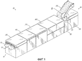
Фиг.1 представляет собой вид в перспективе, иллюстрирующий участок машины для обработки, предназначенной для заполнения конвертов отобранными бумажными или пленочными предметами;Figure 1 is a perspective view illustrating a portion of a processing machine for filling envelopes with selected paper or film objects;
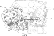
фиг.2 представляет собой вертикальную проекцию участка устройства для заполнения или наполнения машины для обработки согласно фиг.1, более конкретно связанного с зоной 2, выделенной кружком на фиг.1;figure 2 is a vertical projection of a portion of the device for filling or filling the machine for processing according to figure 1, more specifically associated with the
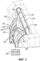
фиг.3 представляет собой вид в перспективе вакуумного барабана и основного ролика устройства для вкладывания согласно фиг.2;FIG. 3 is a perspective view of a vacuum drum and a main roller of the insertion device of FIG. 2;
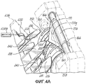
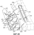
фиг.4А представляет собой вид, подобный виду на фиг.3, на котором дополнительно показан узел для вкладывания листа устройства для вкладывания согласно фиг.2;FIG. 4A is a view similar to that of FIG. 3, which further shows a sheet insertion unit of the insertion device of FIG. 2;
фиг.4В представляет собой вид, подобный виду на фиг.4A, на котором показан конверт в положении, отличающемся от положения, показанного на фиг.4А;FIG. 4B is a view similar to that of FIG. 4A, showing an envelope in a position different from that shown in FIG. 4A;
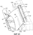
фиг.4С представляет собой вид, подобный видам на фиг.4А-4В, на котором показан конверт в другом отличающемся положении;FIG. 4C is a view similar to the views of FIGS. 4A-4B showing an envelope in another different position;
фиг.4D представляет собой вид, подобный видам на фиг 4А-4С, на котором показан конверт еще в положении, отличном от показанных на фиг.4А-4С;FIG. 4D is a view similar to the views of FIGS. 4A-4C, showing an envelope still in a position different from that shown in FIGS. 4A-4C;
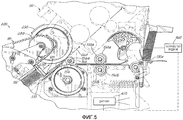
фиг.5 представляет собой вид, подобный виду на фиг.2, на котором показан этап процесса вкладывания;Fig. 5 is a view similar to that of Fig. 2, which shows a step of the insertion process;
фиг.6 представляет собой вид, подобный виду на фиг.2 и 5, на котором показан участок устройства для транспортировки конвертов;Fig.6 is a view similar to that of Fig.2 and 5, which shows a portion of the device for transporting envelopes;
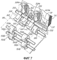
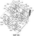
фиг.7 представляет собой вид в перспективе участка устройства для транспортировки конвертов согласно фиг.6;Fig.7 is a perspective view of a portion of the device for transporting envelopes according to Fig.6;
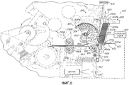
фиг.8 представляет собой вид, подобный виду на фиг.6, на котором показан этап в процессе транспортировки конвертов;Fig. 8 is a view similar to that of Fig. 6, which shows a step in the process of transporting envelopes;
фиг.8А представляет собой вид, подобный виду на фиг.7, на котором показан участок устройства для транспортировки конвертов на этапе, показанном на фиг.8; иfiga is a view similar to that of Fig.7, which shows a portion of the device for transporting envelopes in the step shown in Fig.8; and
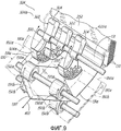
фиг.9 представляет собой вид, подобный виду на фиг.7 и 8А, на котором показан другой этап обработки для транспортировки конвертов.Fig.9 is a view similar to the view of Fig.7 and 8A, which shows another processing step for transporting envelopes.
Подробное описание изобретенияDETAILED DESCRIPTION OF THE INVENTION
На чертежах и, более конкретно, на фиг.1, показан участок приведенной в качестве примера машины 10 для обработки, предназначенной для обработки полотна 12 бумаги или пленки. Хотя и не показано, полотно 12, обрабатываемое машиной 10 для обработки, поступает, например, из рулона (не показан) материала, содержащего такое полотно. Рулон в целом соединен с первым концом 14 машины 10 для обработки и разматывается известными в технике способами, например, путем приведения в действие шпинделя, на котором надет сердечник рулона, или путем взаимодействия поверхности рулона с лентой или подобным устройством. Обычно на полотне 12 предварительно напечатаны штампы в отдельных зонах.In the drawings and, more specifically, in FIG. 1, a portion of an
Таким образом, полотно 12 перемещается в продольном направлении, в целом указанном стрелкой 15, через несколько модулей, которые составляют машину 10 для обработки. В приведенном в качестве примера варианте осуществления настоящего изобретения согласно фиг.1, машина 10 для обработки разрезает материал полотна на отдельные листы (соответствующие «зонам») материала («вкладыши») и подает их в конверты, подаваемые обычно с противоположного конца 16 машины 10 для обработки. Машина 10 для обработки может, кроме того, транспортировать содержащие вкладыши конверты от показанного участка машины 10 для обработки для последующей обработки или выгрузки. Приведенная в качестве примера машина 10 для обработки включает в себя, как отмечено выше, несколько модулей для осуществления различных этапов обработки полотна и получающихся из него вкладышей, также как и для обработки конвертов. Специалистам в данной области техники должно быть хорошо понятно, что машина 10 для обработки может включать в себя другие модули, в дополнение или вместо тех, которые показаны здесь.Thus, the
Первым из показанных модулей является, например, модуль 30 резки, относительно проксимальный к первому концу 14 машины 10 для обработки, который разрезает полотно 12 на отдельные предметы, такие как вкладыши (не показаны) для последующей обработки. Модуль 40 для транспортировки контролирует и транспортирует отдельные вкладыши, принятые из модуля резки, и подает их в модуль 50 фальцовки и промежуточного хранения. Модуль 50 может, если это необходимо, формировать стопки из отдельных вкладышей для последующей обработки, например, если назначение производства требует заполнения конвертов вкладышами, образованными более чем одним отдельным листом. Модуль 50 фальцует отдельные листы, если это требуется назначением производства, вдоль продольной оси отдельных вкладышей, расположенных обычно вдоль продольного направления. Кроме того, модуль 50 собирает, подбирает или осуществляет промежуточное хранение наборов отдельных листов в отдельно упакованные стопки, если конкретное производство требует этого.The first of the modules shown is, for example, a
Как опять же видно на фиг.1, модуль 60 ввода принимает вкладыши из модуля 50 фальцовки и промежуточного хранения и объединяет с компонентами из модуля 70 заполнения, чтобы транспортировать вкладыши и подавать их в конверты. Конверты, в свою очередь, транспортируются и подаются к модулю 70 заполнения транспортером 80 для конвертов. Транспортный узел 90 технологически соединен с модулем 70 заполнения и транспортером 80 для конвертов для транспортировки заполненных или наполненных конвертов от показанного участка машины 10 для обработки для последующей обработки или размещения.As again shown in FIG. 1, the
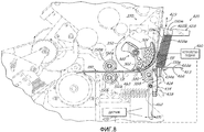
На фиг.2 более подробно показан приведенный в качестве примера модуль 70 заполнения. Модуль 70 включает в себя раму 72, которая несет систему вкладывания или устройство 100, которое подает отдельные листы или вкладыши к конвертам, подает конверты к отдельным листам, вкладывает отдельные листы в конверты и перемещает заполненные конверты к транспортному узлу 90 (фиг.1). С этой целью устройство 100 включает в себя устройство 110 подачи в виде ленточного узла 112, вращающегося по замкнутому контуру (показан только частично) и приводимого в действие с помощью зубчатого колеса 114. Множество пальцев 116 выступают из ленточного узла 112 и разнесены вдоль длины ленточного узла 112. Пальцы 116 входят в зацепление с задними кромками вкладышей 120, чтобы посредством этого перемещать их к конвертам 130 в общем направлении стрелки 134, в то время как конверты 130 перемещаются по направлению к вкладышам 120 в общем направлении стрелки 138. В данном приведенном в качестве примера варианте осуществления настоящего изобретения множество отклоняемых элементов в виде щетинок 140 образуют часть опорных элементов 142 устройства 110 подачи. Щетинки 140 входят в зацепление с вкладышами 120 по мере их перемещения к конвертам 130.2, an
Как отмечено выше, конверты 130 сначала перемещаются в основном направлении стрелки 138 к вкладышам 120. Это перемещение конвертов 130 обеспечивается взаимодействием между вращающимся вакуумным барабаном 150 и вращающимся основным роликом 156, которые зажимают каждый конверт 130. Вакуумный барабан 150 и основной ролик 156 поддерживаются со стороны рамы 158 (показанной штрихпунктирной линией на фиг.3) модуля 70 заполнения. Когда вакуумный барабан 150 и основной ролик 156 вращаются в противоположных друг другу направлениях, зацепление с расположенным между ними конвертом 130 приводит к тому, что конверт 130 перемещается по направлению к вкладышам 120 в секции вкладывания или заполнения. Более конкретно, вакуумный барабан 150 вращается в направлении, указанном стрелкой 160 (против часовой стрелки), в то время как основной ролик 156 вращается в направлении, указанном стрелкой 166 (по часовой стрелке). Расстояние между вакуумным барабаном 150 и основным роликом 156 выбрано соответствующим образом, чтобы эффективно зажимать конверт 130 между ними. Поэтому, в этом отношении, данное расстояние выбирают на основе факторов, включающих, но не ограниченных этим, заданную толщину конвертов 130. Хотя и не показано, один или оба из вакуумного барабана 150 и основного ролика 156, могут быть регулируемыми, чтобы посредством этого обеспечить регулировку расстояния между ними.As noted above,
Материалы для вакуумного барабана 150 и основного ролика 156 выбирают соответствующим образом, чтобы обеспечить зацепление и перемещение конвертов в направлении стрелки 138. Например, но без ограничений, по меньшей мере наружная поверхность, если не значительный участок основного ролика 156, может быть изготовлена из резины, уретана или других материалов, обеспечивающих заданный уровень трения с конвертами 130. Подобным образом, по меньшей мере поверхность 170 вакуумного барабана 150 изготовлена из металла, такого как нержавеющая сталь, которая может быть дополнительно покрыта поверхностью или текстурой расцепляющего типа, чтобы предотвратить, например, налипание клеящего вещества или других материалов на поверхность 170.The materials for the
Вакуумный барабан 150 и основной ролик 156 принимают каждый конверт из направляющих 180 (только одна показана на виде на фиг.2), образованных расположенными напротив друг друга рельсами 182а, 182b, которые направляют конверты 130. Более конкретно, рельсы 182а, 182b образуют между собой пространство, которое принимает боковые участки 130а (фиг.4) каждого конверта 130. Две пары (показана только одна) приводных вспомогательных роликов 190а, 190b расположены между направляющими 180 для облегчения перемещения конвертов, направляемых направляющими 180. Более конкретно, ролики 190а, 190b вращаются в противоположных друг другу направлениях (стрелки 192а, 192b) и расположены так, чтобы зажимать центральный участок конвертов 130, чтобы посредством этого перемещать конверты 130 к вкладышам 120.The
Как видно на фиг.2 и дополнительно на фиг.3, вакуумный барабан 150 на поверхности 170 включает в себя множество отверстий 200, выполненных с возможностью обеспечения перемещения конвертов 130 при вращении вакуумного барабана 150. Более конкретно, отверстия 200 находятся в сообщении по текучей среде со схематично обозначенным источником вакуума 204 для создания отрицательного давления на поверхности 170 вакуумного барабана 150. За счет отрицательного давления происходит зацепление конвертов 130 и удерживание конвертов 130, предотвращая или минимизируя перемещение конвертов 130 относительно вакуумного барабана 150, когда вакуумный барабан 150 вращается.As can be seen in FIG. 2 and additionally in FIG. 3, the
В этом приведенном в качестве примера варианте осуществления настоящего изобретения источник 204 вакуума является непрерывно работающим, то есть он постоянно находится в состоянии «включено». Кроме того, вакуумный барабан 150 управляется электрически путем, например с помощью сервопривода, чтобы облегчить избирательное приложение отрицательного давления к выбранным группам отверстий 200 и, таким образом, к выбранным участкам поверхности 170 вакуумного барабана 150. Выбор отверстий 200, к которым источник 204 вакуума направляет отрицательное давление, производят, например, на основе шага или длины 130L конвертов 130. В этом отношении вакуумный барабан 150 может быть повернут относительно источника 204 вакуума, чтобы совместить источник 204 вакуума с требуемой группой отверстий 200, которые с помощью вращающейся поверхности 170 обеспечивают зацепление конкретного типа конвертов 130 и/или выбранного участка конверта 130. Например, вакуумный барабан 150 может быть повернут относительно источника 204 вакуума так, что отрицательное давление не прикладывается к заднему участку конверта 130, что может облегчить освобождение конверта 130 от источника 204 вакуума.In this exemplary embodiment of the present invention, the
Вакуумный барабан 150 включает в себя два боковых участка 150а, 150b, имеющих одинаковые конструкции и вращающиеся от общего центрального сердечника 150с. Отверстия 200, в этом отношении, расположены на обоих боковых участках 150а, 150b, чтобы посредством этого обеспечить равномерное зацепление конвертов 130. Соответственно, приведенное в качестве примера размещение отверстий 200 в этом варианте осуществления настоящего изобретения предотвращает или по меньшей мере минимизирует перекос конвертов 130, когда они перемещаются при вращении вакуумного барабана 150.The
Как видно на фиг.2-3, наклонный элемент 210 соединен с вакуумным барабаном 150, чтобы обеспечить отсоединение конвертов 130 от поверхности 170 вакуумного барабана 150. Более конкретно, наклонный элемент 210 является неподвижным относительно вакуумного барабана 150 и расположен между двумя боковыми участками 150а, 150b вакуумного барабана 150. Наклонный элемент 210 выполнен в виде твердого блока, имеющего поверхность, которая в целом является касательной к поверхности 170 вакуумного барабана 150. При работе, как только конверт 130 перемещается при вращении вакуумного барабана 150 (стрелки 160), передний участок 130f конверта 130 скользит по наклонному элементу 210, чтобы посредством этого отцепить передний участок 130f от поверхности 170 вакуумного барабана 150.As can be seen in FIGS. 2-3, the
Специалистам в данной области техники будет понятно, что в альтернативном варианте наклонный элемент 210 мог бы принимать другие формы, при условии, что он выполнен с возможностью быть в целом касательным к поверхности 170 вакуумного барабана 150. Подобным образом, предполагается, что в альтернативном варианте наклонный элемент 210 мог бы быть перемещающимся элементом, а не полностью неподвижным, при условии, что он является неподвижным относительно вакуумного барабана 150. Например, и без ограничений, альтернативный вариант осуществления настоящего изобретения может включать в себя наклонный элемент, который перемещается в том же направлении или в противоположном направлении относительно вакуумного барабана с тем, чтобы образовать неподвижный наклонный элемент относительно вакуумного барабана 150.It will be understood by those skilled in the art that, alternatively, the
На фиг.4А-4D показана приведенная в качестве примера операция вкладывания. На фиг.4А показан конверт 130, перемещающийся при вращении (стрелки 160) вакуумного барабана 150. Отверстия 200 находятся в сцеплении с большей частью длины конверта 130. Ориентация конверта 130 является такой, что передний участок 130f конверта является клапаном конверта. Кроме того, ориентация является такой, что образующая клапан конверта 130 основа бумаги 130g обращена к поверхности 170 вакуумного барабана 150, в то время как противоположная основа 130h (фиг.4В) обращена к основному ролику 156. Специалистам будет понятно, что данная ориентация является только примером и вместо нее могут быть осуществлены другие альтернативные ориентации.4A-4D show an exemplary insertion operation. FIG. 4A shows an
На фиг.4А также показан передний участок 130f конверта 130, начинающий входить в зацепление с наклонным элементом 210. Кроме того, конверт 130 показан перемещающимся к паре наружных расширительных элементов 216 и к центральному расширительному элементу 218 устройства 220 для транспортировки. Устройство 220 для транспортировки транспортирует вкладыши 120 (фиг.4В) по направлению к конверту 130 и включает в себя устройство 110 подачи и описанные выше опорные элементы 142 (фиг.2). В этом приведенном в качестве примера варианте осуществления настоящего изобретения устройство 220 для транспортировки, кроме того, включает в себя пару зажимов 232 (показан только один), продолжающихся от рамы 236 (показана штрихпунктирными линиями) устройства 220. Устройство 220 для транспортировки, в данном варианте осуществления настоящего изобретения, также включает в себя пару направляющих элементов 242, которые облегчают направление вкладышей 120 в конверт 130. Положения зажимов 232 регулируются посредством схематично изображенных двигателей 232а (показан только один), технологически соединенных с зажимами 232 посредством вертикальных ходовых винтов (не показаны), которые обеспечивают автоматическое регулирование положений зажимов 232 в ответ на длину 130L конвертов 130. Более конкретно, двигатели 232а облегчают регулировку положения зажимов 232 по направлению к основному ролику 156 и от него. Двигатели 232а могут быть, например, шаговыми двигателями, такими как модель HRA08C, поставляемая Sick Stegmann GmbH, членом группы Sick AG Group of Waldkirch, Германия.4A also shows the
На фиг.4В конкретно показан конверт 130, частично вошедший в зацепление с расширительными элементами 216, 218 таким образом, что расширительные элементы 216, 218 продолжаются во внутренний участок 130n конверта 130. На этом этапе процесса вкладывания и по отношению к этапу, показанному на фиг.4А, больший участок длины 130L (фиг.2) конверта 130 входит в зацепление с наклонным элементом 210 и соответственно расцепляется с поверхностью 170 вакуумного барабана 150 (фиг.4А). На этом этапе подобным образом вкладыш 120 показан перемещающимся, в направлении стрелки 250, к внутреннему участку 130n конверта 130. Вкладыш 120 показан с передним краем 120L, направленным в сторону к внутреннему участку 130n.FIG. 4B specifically shows an
На фиг.4С конкретно показана стадия процесса вкладывания, на которой конверт 130 полностью или по меньшей мере большей частью расцепляется с поверхностью 170 вакуумного барабана 150 (фиг.4А). В этом отношении вращение вакуумного барабана 150 является таким, что конверт 130 скользит относительно вращательного движения вакуумного барабана 150. Зажимы 232 (показан только один) показаны входящими в зацепление с конвертом 130 так, чтобы обеспечить останавливающую или ограничивающую поверхность в перемещении (стрелка 138) конверта 130 по направлению к вкладышу 120. Пальцы 116 (показаны штрихпунктирной линией) показаны входящими в зацепление с задней кромкой 120t вкладыша 120 и посредством этого перемещающими вкладыш 120 (стрелка 250) по направлению к внутреннему участку 130n конверта 130. Кроме того, зажимы 232 создают подъемное действие для конверта 130 так, что при дополнительном перемещении конверта 130 в направлении стрелки 138 задняя кромка 130t конверта 130 выталкивается вверх (стрелки 260) и выше основного ролика 156, как показано на фиг.4D. Используемые здесь термины «вверх», «верхний», «нижний», «выше», «вперед», «передний» «задний» и их производные не предназначены быть ограничивающими, но скорее только отражают иллюстративные ориентации, показанные на чертежах.On figs specifically shows the stage of the insertion process, in which the
На фиг.4D конкретно показана стадия процесса вкладывания, на которой перемещение пальцев 116 (стрелка 250) вперед приводит к перемещению конверта в подобном направлении (стрелка 264), обычно от устройства 220 для транспортировки в секции вкладывания или заполнения и в направлении к транспортному узлу 90 (фиг.1) для последующего расположения заполненного конверта 130. Более конкретно, на стадии процесса, показанной на фиг.4D, передняя кромка 120L вкладыша 120 достигает задней кромки 130t конверта 130. Соответственно, перемещение пальцев 116 вперед оказывает через вкладыш 120 усилие на заднюю кромку 130t конверта 130, что приводит к перемещению заполненного конверта 130 в направлении стрелки 264.FIG. 4D specifically shows a stage of the insertion process in which moving the fingers 116 (arrow 250) forward causes the envelope to move in a similar direction (arrow 264), typically from the
Как опять же показано на фиг.4D и дополнительно - на фиг.5, вращение основного ролика 156 (стрелка 166) содействует перемещению наполненного конверта 130 в направлении стрелки 264. Более конкретно, вращающийся транспортирующий ролик 288 расположен так, чтобы образовывать небольшое пространство между транспортирующим роликом 288 и основным роликом 156. Транспортирующий ролик 288 в альтернативном варианте может быть выполнен в виде любого другого вращающегося элемента, такого, как например, вращающийся элемент неправильной формы, и, таким образом, не ограничен круглым вращающимся элементом, как показано в данном варианте осуществления настоящего изобретения. Транспортирующий ролик 288 вращается в направлении (стрелка 290), противоположном направлению вращения основного ролика 156. Положение транспортирующего ролика 288, также как и направление его вращения (стрелка 290) относительно направления вращения (стрелка 166) основного ролика 156, обеспечивает зажимное зацепление заполненного конверта 130 и его транспортировку в направлении стрелки 264. В этом конкретном варианте осуществления настоящего изобретения транспортирующий ролик 288 вращается в направлении против часовой стрелки, хотя это направление не предназначено быть ограничивающим, но скорее является примером. Соответственно, вращение основного ролика 156 в направлении стрелки 166 обеспечивает перемещение конверта 130 в первом направлении (стрелка 138) во время стадии процесса вкладывания, одновременно обеспечивая перемещение конверта 130 во втором направлении (стрелка 250), противоположном первому направлению (стрелка 138), и с противоположной стороны оси 156а вращения основного ролика 156 во время другой стадии процесса.As again shown in FIG. 4D and further in FIG. 5, the rotation of the main roller 156 (arrow 166) facilitates the movement of the filled
Как видно на фиг.6-8, 8А и 9 и как описано выше, вспомогательные ролики 190а, 190b входят в зацепление с центральным участком каждого конверта 130, чтобы посредством этого перемещать конверты 130 вдоль направляющих 180. В этом отношении конверты 130 входят в направляющие 180 за счет действия вращающегося захватного элемента 320, который входит в зацепление с передним участком 130f каждого из конвертов 130. Более конкретно, захватный элемент 320 является вращающейся конструкцией неправильной формы, имеющей центральный участок 322 и наружные участки 324, которые оба включают в себя соответствующие периферийные поверхности 322а, 324а для вхождения в зацепление с конвертами 130.As can be seen in FIGS. 6-8, 8A and 9, and as described above, the
Центральный участок 322 расположен по окружности напротив наружных участков 324 относительно направления его вращения (стрелка 352). Кроме того, центральный участок 322 по этому приведенному в качестве примера варианту осуществления настоящего изобретения является независимо подвижным относительно наружных участков 324, так что положения этих двух участков 322, 324 захватного элемента 320 могут быть отрегулированы относительно друг друга. Регулировка может потребоваться, например, чтобы разместить конверты, имеющие различную длину 130L. Захватный элемент 320 расположен рядом с устройством, несущим стопку конвертов, чтобы совместно образовать устройство 350 для транспортировки конвертов, детали которого описаны более подробно ниже.The
В данном приведенном в качестве примера варианте осуществления настоящего изобретения захватный элемент 320 вращается, и как отмечено выше, в направлении стрелки 352. С этой целью и с конкретной ссылкой на стадию процесса, показанную на фиг.6, передний участок, в данном варианте осуществления настоящего изобретения, в виде клапана 131f первого конверта 131 из стопки конвертов 130 показан до его вхождения в зацепление с захватным элементом 320. Кроме того, первый конверт 131 показан ориентированным так, что клапан 131f является шарнирно подвижным в целом в направлении стрелки 360.In this exemplary embodiment of the present invention, the
На фиг.7 конкретно показан захватный элемент 320, частично входящий в зацепление с конвертом 131. Более конкретно, центральный участок 322 захватного элемента 320 показан достаточно повернутым для того, чтобы войти в зацепление с клапаном 131f первого конверта 131, посредством чего заставляя клапан 131f шарнирно поворачиваться в направлении стрелки 360. Кроме того, наружные участки 324 показаны до вхождения в зацепление с первым конвертом 131.7 specifically shows a gripping
Конкретно ссылаясь на фиг.8-8А, показан захватный элемент 320, дополнительно повернутый (стрелки 376,378) в направлении стрелки 352 так, что центральный участок 322 и наружные участки 324 входят в зацепление с клапаном 131f первого конверта 131. В этом отношении поворот наружных участков 324 приводит к вхождению в зацепление наружных участков 324 с набором копировальных роликов 380, изготовленных, например и без ограничения, из резины или уретана. Положение копировальных роликов 380 относительно наружных участков 324 является таким, что они совместно зажимают клапан 131f, вызывая поворот копировальных роликов 380 (стрелка 388) и перемещение вперед конверта 130 в направлении стрелки 382. На фиг.8-8А также показано частичное вхождение в зацепление захватного элемента 320 с отдельными участками 131m конверта 131. Зацепление отдельных участков 131m, отличных от клапана 131f, облегчает плавную транспортировку конверта 131 по направлению к направляющим 180.Specifically, referring to FIGS. 8-8A, a gripping
На фиг.9 показан захватный элемент 320, дополнительно повернутый (стрелки 390) относительно вида по фиг.8-8А. Конверт 131 показан в таком положении, когда его боковые участки 131а вошли в направляющие 180 (показанные штрихпунктирными линиями). В этом отношении рельсы 182а, 182b направляющих 180 расположены под углом друг к другу на входном участке 180е направляющих 180, чтобы облегчить перемещение боковых участков 131а в пространство, образованное между рельсами 182а, 182b. Кроме того, на показанном виде центральный участок 322 захватного элемента не находится больше в зацеплении с конвертом 131, в то время как наружные участки 324 поворачиваются от конверта 131 и таким образом расцепляются с конвертом 131. Хотя это и не показано, как только захватный элемент 320 продолжает поворачиваться (стрелки 390), он входит в зацепление с новым первым конвертом 131 из стопки конвертов 130.FIG. 9 shows a gripping
Как опять же показано на фиг.6, захватный элемент 320 удаляет первый конверт 131 из стопки конвертов, которую несет система 420 для транспортировки конвертов и которая непрерывным образом подает конверты 130. Система 420 для транспортировки конвертов включает в себя опорную пластину 422, смонтированную на рамной конструкции 424 и неподвижную относительно нее. Опорная пластина включает в себя в целом плоскую поверхность 422а, которая выполнена с возможностью опоры для в целом горизонтальной стопки конвертов 130, каждый в целом в вертикальной ориентации. Кроме того, в данном приведенном в качестве примера варианте осуществления настоящего изобретения опорная пластина 422 включает в себя наклонную плоскость 423, чтобы облегчить прием конвертов 130. Используемые здесь термины «вертикальный» и «в целом горизонтальный» не должны рассматриваться, соответственно, как ограниченные четко вертикальным или горизонтальным направлениями конвертов 130 или стопки конвертов, но скорее как ориентация, посредством которой они удерживаются в поперечном направлении. В этом отношении, следовательно, и как показано на фиг.6, конверты 130 удерживаются в поперечном направлении (вдоль нижних кромок 130е), в целом в вертикальной ориентации, образуя, таким образом, острый угол относительно поверхности 422а опорной пластины.As again shown in FIG. 6, the gripping
Стопорный элемент 428 системы 420 для транспортировки конвертов подобным образом поддерживается рамной конструкцией 424 и смонтирован в неподвижной ориентации относительно опорной пластины 422. Стопорный элемент 428 включает в себя передний участок 428а, который несет переднюю или обращенную вперед сторону 131w первого конверта 131 из стопки конвертов 130. Верхний участок 428b стопорного элемента 428 поддерживает верхние кромки 130u конвертов 130. В этом отношении стопорный элемент 428 выполнен с возможностью вертикального регулирования (стрелка 429), чтобы разместить конверты 130 с различным шагом или различной длины 130L. Схематично обозначенный двигатель 430 технологически соединен посредством вертикального ходового винта (не показано) со стопорным элементом 428, чтобы облегчить автоматическую регулировку вертикального положения стопорного элемента 428 в ответ на длину 130L. Например, но без ограничения, двигатель 430 может быть моделью HRA08C шагового двигателя, поставляемой Sick Stegmann GmbH, членом группы Sick AG Group of Waldkirch, Германия. Стопорный элемент 428 и опорная пластина 422 совместно поддерживают конверты 130 в целом в вертикальной ориентации, показанной на фиг.6.The locking
Как опять же показано на фиг.6, чувствительный к давлению рычаг 434 системы 420 для транспортировки конвертов ориентирован в целом поперечно к опорной пластине 422 и является подвижным с возможностью поворота вокруг оси поворота 440, неподвижно прикрепленной к рамной конструкции 424. Чувствительный к давлению рычаг 434 включает в себя сенсорную поверхность 434а, которая входит в зацепление с первым конвертом 131 из стопки конвертов 130. Чувствительный к давлению рычаг 434 имеет продолжающийся от оси поворота 440 первый участок 436, который включает в себя сенсорную поверхность 434а. Второй участок 438 чувствительного к давлению рычага 434 также продолжается от оси поворота 440 и в направлении от первого участка 436. В этом варианте осуществления настоящего изобретения первый участок 436 короче, чем второй участок 438. При работе первый конверт 131 находится в положении подачи и ориентирован так, что клапан 131f первого конверта 131 продолжается в область, расположенную ниже по ходу (то есть за) от сенсорной поверхности 434а.As again shown in FIG. 6, the pressure-sensitive lever 434 of the
Схематично обозначенный датчик 450 технологически соединен, или в положении считывания, со вторым участком 438 для управления устройством 460 подачи системы 420 для транспортировки конвертов. Устройство 450 подачи оказывает усилие подачи на стопку конвертов 120, которое смещает стопку к положению подачи конверта, показанному на фиг.6. Датчик 450 в данном варианте осуществления настоящего изобретения является датчиком инфракрасного типа, который расположен нацеленным на расширение 462, соединенное со вторым участком 438 чувствительного к давлению рычага 434, и выполнен с возможностью обнаружения перемещения расширения 462. В этом приведенном в качестве примера варианте осуществления настоящего изобретения расширение 462 соединено с рамной конструкцией 424 через узел 463 пружины и крючка (показан штрихпунктирными линиями), чтобы направлять перемещение расширения 462 вдоль направлений стрелки 470, и при заданном смещении пружины удерживать чувствительный к давлению рычаг 434 у первого (то есть ведущего) конверта 131. В этом отношении перемещение расширения 462 (стрелка 470) является результатом соответствующего перемещения первого участка 436 чувствительного к давлению рычага 434 и вызвано усилием подачи, оказываемым стопкой конвертов 130 на сенсорную поверхность 434а.A schematically indicated
Более конкретно, усилие, оказываемое стопкой конвертов 130 на сенсорную поверхность 434а, является результатом усилия подачи или усилия смещения, приложенного к стопке устройством 460 подачи. Это усилие подачи или смещения, в свою очередь, определяет величину давления, действующего на первый конверт 131, удерживаемый между другими конвертами 130 стопки и передним участком 428а стопорного элемента 428. Давление, действующее на первый конверт 131, в свою очередь определяет усилие, необходимое для удаления первого конверта 131 из стопки конвертов 130.More specifically, the force exerted by the stack of
В данном варианте осуществления настоящего изобретения устройство 460 подачи технологически соединено с датчиком 450. В этом отношении, когда датчик 450 определяет перемещение расширения 462 (стрелка 470), датчик 450 посылает соответствующий сигнал на устройство 460 подачи. В ответ на этот сигнал устройство 460 подачи снижает или увеличивает величину усилие подачи, которое оно прикладывает к стопке конвертов 130, и, таким образом, давление, действующее на чувствительный к давлению рычаг 434 и стопорный элемент 428. Соответственно, устройство 460 подачи выполнено с возможностью контроля давления, действующего на первый конверт 131 из стопки конвертов 130, чтобы таким образом поддерживать его на требуемом заданном уровне, чтобы облегчить удаление первого конверта 131 из стопки. В качестве примера, но без ограничения, устройство подачи во время работы может подавать конверты 130 с первым усилием подачи и соответствующим давлением, оказываемым на передний участок 428а стопорного элемента 428. Это первое усилие приводит к поворотному перемещению чувствительного к давлению рычага 434. Датчик 450 обнаруживает перемещение расширения 462, связанное с этим усилием. Датчик 450, в свою очередь, посылает соответствующий сигнал на устройство 460 подачи, которое в ответ на сигнал регулирует усилие подачи, с которым оно подает конверты 130, например, до более низкого второго усилия подачи. Это более низкое второе усилие подачи приводит к более низкому давлению, оказываемому на передний участок 428а стопорного элемента 428, которое, в свою очередь, приводит к меньшему отклонению чувствительного к давлению рычага 434.In this embodiment of the present invention, the
Хотя настоящее изобретение было проиллюстрировано с помощью описания различных вариантов осуществления настоящего изобретения, и хотя эти варианты осуществления настоящего изобретения были описаны достаточно подробно, это не предполагает ограничивать или каким-либо путем лимитировать объем приложенной формулы изобретения до подобных подробностей. Дополнительные преимущества и модификации будут легко понятны специалистам. Поэтому изобретение в своих самых широких аспектах не ограничено конкретными деталями, представляющими устройство и способ, а также показанными и описанными иллюстративными примерами. Соответственно, можно выйти за эти подробности, не выходя за рамки сущности или объема общего изобретательского замысла.Although the present invention has been illustrated by describing various embodiments of the present invention, and although these embodiments of the present invention have been described in sufficient detail, this is not intended to limit or in any way limit the scope of the attached claims to such details. Additional benefits and modifications will be readily apparent to those skilled in the art. Therefore, the invention in its broadest aspects is not limited to the specific details representing the device and method, as well as the illustrative examples shown and described. Accordingly, one can go beyond these details without going beyond the essence or scope of the general inventive concept.
Claims (29)
устройство подачи для перемещения предмета к конверту;
вакуумный барабан с поверхностью, выполненной с возможностью вхождения в зацепление и перемещения конверта к предмету; и
наклонный элемент, соединенный с упомянутым вакуумным барабаном и включающий в себя в целом плоскую поверхность, касательную к вакуумному барабану и выполненную с возможностью поддержки конверта, когда конверт перемещается вакуумным барабаном.1. A device for inserting a paper or film subject or a stack of similar items in an envelope containing:
feeder for moving the item to the envelope;
a vacuum drum with a surface configured to engage and move the envelope to the subject; and
an inclined element connected to said vacuum drum and including a generally flat surface tangential to the vacuum drum and configured to support the envelope when the envelope is moved by the vacuum drum.
первый вращающийся элемент, вращающийся в первом направлении вращения, для перемещения конверта в первом направлении перемещения по направлению к предмету.5. The device according to claim 1, additionally containing:
a first rotating member rotating in a first direction of rotation to move the envelope in a first direction of movement toward the subject.
второй вращающийся элемент, взаимодействующий с упомянутым первым вращающимся элементом, чтобы перемещать конверт во втором направлении перемещения.7. The device according to claim 6, further comprising:
a second rotating element cooperating with said first rotating element to move the envelope in the second direction of movement.
по меньшей мере один зажим для ограничения перемещения конверта к предмету.12. The device according to claim 1, additionally containing:
at least one clip to limit the movement of the envelope to the subject.
двигатель, технологически соединенный с упомянутым по меньшей мере одним зажимом для автоматического регулирования положения упомянутого зажима в ответ на длину конверта.13. The device according to item 12, further comprising:
an engine technologically connected to said at least one clip for automatically adjusting the position of said clip in response to the length of the envelope.
устройство подачи для перемещения предмета к конверту;
вакуумный барабан, имеющий поверхность, выполненную с возможностью вхождения в зацепление и перемещения конверта к предмету, и источник вакуума, непрерывно создающий отрицательное давление на указанной поверхности;
наклонный элемент, соединенный с вакуумным барабаном и являющийся неподвижным относительно него, причем наклонный элемент включает в себя в целом плоскую поверхность, касательную к упомянутому вакуумному барабану и выполненную с возможностью поддержки конверта, когда конверт перемещается упомянутым вакуумным барабаном.14. A device for inserting a paper or film subject or a pile of similar items into an envelope containing:
feeder for moving the item to the envelope;
a vacuum drum having a surface configured to engage and move the envelope to the subject, and a vacuum source that continuously creates negative pressure on said surface;
an inclined element connected to the vacuum drum and being stationary relative to it, and the inclined element includes a generally flat surface tangent to said vacuum drum and configured to support the envelope when the envelope is moved by said vacuum drum.
устройство для вкладывания отдельных листов бумаги в конверты, причем упомянутое устройство включает в себя:
(a) устройство подачи для вкладывания отдельных листов бумаги по направлению к конвертам,
(b) вакуумный барабан, имеющий поверхность, выполненную с возможностью зацепления и перемещения конвертов к отдельным листам, и
(с) наклонный элемент, соединенный с вакуумным барабаном и включающий в себя в целом плоскую поверхность, касательную к вакуумному барабану и выполненную с возможностью поддержки конвертов, когда конверты перемещаются с вакуумным барабаном.15. An automatic device for filling an envelope having a first end associated with feeding a paper roll, and a processing device for converting a paper roll into separate sheets, the device for filling envelopes further comprises:
a device for inserting individual sheets of paper into envelopes, said device including:
(a) a feeder for loading individual sheets of paper toward the envelopes,
(b) a vacuum drum having a surface adapted to engage and move envelopes to individual sheets, and
(c) an inclined member connected to the vacuum drum and including a generally flat surface tangent to the vacuum drum and configured to support envelopes when the envelopes are moved with the vacuum drum.
упомянутый вакуумный барабан является серво управляемым и включает в себя множество отверстий, образующих поверхность для вхождения в зацепление с конвертом, и источник вакуума, находящийся в сообщении по текучей среде с упомянутым множеством отверстий для выборочного приложения отрицательного давления через одно или более из упомянутого множества отверстий.16. The device according to clause 15, in which
said vacuum drum is servo-driven and includes a plurality of openings forming a surface for engaging with an envelope, and a vacuum source in fluid communication with said plurality of openings for selectively applying negative pressure through one or more of said plurality of openings.
упомянутый вакуумный барабан включает в себя источник вакуума, который непрерывно создает отрицательное давление на поверхности упомянутого вакуумного барабана.17. The device according to clause 15, in which
said vacuum drum includes a vacuum source that continuously creates negative pressure on the surface of said vacuum drum.
перемещение предмета к секции вкладывания;
приложение отрицательного давления к конверту, чтобы конверт вошел в зацепление с вращающейся поверхностью;
перемещение вращающейся поверхности, чтобы перемещать конверт к секции вкладывания; и
поддержку переднего участка конверта с помощью относительно неподвижной поверхности, когда конверт перемещается вращающейся поверхностью.19. A method of inserting a paper or film item or a stack of similar items into an envelope, including:
moving the item to the insertion section;
applying negative pressure to the envelope so that the envelope engages with a rotating surface;
moving a rotating surface to move the envelope to the nesting section; and
supporting the front portion of the envelope with a relatively fixed surface when the envelope is moved by a rotating surface.
подъем переднего участка конверта от вращающейся поверхности.20. The method according to claim 19, further comprising:
lifting the front of the envelope from a rotating surface.
вращение первого вращающегося элемента в первом направлении вращения, чтобы перемещать конверт в первом направлении перемещения по направлению к предмету.21. The method according to claim 19, further comprising:
the rotation of the first rotating element in the first direction of rotation to move the envelope in the first direction of movement towards the subject.
вращение первого вращающегося элемента в первом направлении вращения, чтобы перемещать конверт во втором направлении перемещения, противоположном первому направлению перемещения.22. The method according to item 21, further comprising:
the rotation of the first rotating element in the first direction of rotation to move the envelope in the second direction of movement opposite to the first direction of movement.
непрерывное приложение отрицательного давления к вращающейся поверхности.23. The method according to claim 19, further comprising:
continuous application of negative pressure to a rotating surface.
электрически управляемое перемещение вращающейся поверхности относительно источника вакуума для выборочного создания отрицательного давления на выбранных участках вращающейся поверхности.24. The method according to claim 19, further comprising:
electrically controlled movement of the rotating surface relative to the vacuum source to selectively create negative pressure in selected portions of the rotating surface.
перемещение конверта в плоскости, в целом касательной к вращающейся поверхности.25. The method according to claim 19, further comprising:
moving the envelope in a plane generally tangent to the rotating surface.
рамную конструкцию;
опорную пластину, смонтированную на упомянутой рамной конструкции и в целом неподвижную относительно нее, причем упомянутая опорная пластина имеет в целом плоскую поверхность для поддержания стопки конвертов в целом в вертикальной ориентации;
чувствительный к давлению рычаг, смонтированный на упомянутой рамной конструкции и имеющий сенсорную поверхность, ориентированную поперечно к упомянутой опорной пластине, причем упомянутый чувствительный к давлению рычаг является подвижным с возможностью поворота в ответ на давление, оказываемое стопкой конвертов, и упомянутый чувствительный к давлению рычаг расположен по отношению к упомянутой опорной пластине, чтобы позволить переднему участку первого конверта стопки продолжаться в область за упомянутой сенсорной поверхностью;
устройство подачи для перемещения предмета к конверту из стопки конвертов;
вакуумный барабан, поддерживаемый упомянутой рамной конструкцией и имеющий поверхность, выполненную с возможностью вхождения в зацепление и перемещения конверта по направлению к предмету; и
наклонный элемент, соединенный с упомянутым вакуумным барабаном и включающий в себя в целом плоскую поверхность, касательную к упомянутому вакуумному барабану, выполненную с возможностью поддержки конверта, когда конверт перемещается упомянутым вакуумным барабаном.26. A device for processing envelopes and a paper or film subject, or a stack of such items that are to be inserted into envelopes, containing:
frame construction;
a support plate mounted on said frame structure and generally stationary relative to it, said support plate having a generally flat surface for supporting the stack of envelopes in general in a vertical orientation;
a pressure sensitive lever mounted on said frame structure and having a sensor surface oriented transversely to said support plate, said pressure sensitive lever being movable to rotate in response to pressure exerted by the stack of envelopes, and said pressure sensitive lever is located on with respect to said support plate to allow the front portion of the first envelope of the stack to extend into the region beyond said touch surface;
a feeder for moving an item to an envelope from a stack of envelopes;
a vacuum drum supported by said frame structure and having a surface configured to engage and move the envelope toward the subject; and
an inclined element connected to said vacuum drum and including a generally flat surface tangent to said vacuum drum configured to support the envelope when the envelope is moved by said vacuum drum.
перемещение предмета по направлению к секции вкладывания;
приложение отрицательного давления к конверту, чтобы конверт вошел в зацепление с вращающейся поверхностью;
перемещение вращающейся поверхности, чтобы перемещать конверт по направлению к секции вкладывания;
поддерживание переднего участка конверта с помощью относительно неподвижной поверхности, когда конверт перемещается вращающейся поверхностью;
приложение первого усилия к стопке конвертов, чтобы перемещать их к секции вкладывания;
вхождение в зацепление первого конверта стопки с подвижной поверхностью, выполненной с возможностью поворота;
поворотное перемещение подвижной поверхности в ответ на первое усилие; и
приложение второго усилия к стопке конвертов, отличного от первого усилия.27. A method for processing envelopes and a paper or film subject, or a stack of such items that are to be inserted in envelopes, the method comprising:
moving the item towards the insertion section;
applying negative pressure to the envelope so that the envelope engages with a rotating surface;
moving a rotating surface to move the envelope toward the insertion section;
maintaining the front portion of the envelope with a relatively fixed surface when the envelope is moved by a rotating surface;
applying a first effort to the stack of envelopes to move them to the nesting section;
the engagement of the first envelope of the stack with a movable surface, made with the possibility of rotation;
rotational movement of the movable surface in response to the first force; and
applying a second force to the stack of envelopes other than the first force.
перемещение предмета по направлению к секции вкладывания;
приложение отрицательного давления к конверту, чтобы конверт вошел в зацепление с вращающейся поверхностью;
перемещение вращающейся поверхности, чтобы перемещать конверт к секции вкладывания;
смещение стопки конвертов по направлению к положению подачи конверта;
обнаружение давления на переднем конверте в положении подачи, являющегося результатом смещения; и
управление смещением в ответ на это обнаружение.28. A method for processing envelopes and a paper or film subject, or a stack of such items that are to be inserted in envelopes, the method comprising:
moving the item towards the insertion section;
applying negative pressure to the envelope so that the envelope engages with a rotating surface;
moving a rotating surface to move the envelope to the nesting section;
Offset stack of envelopes toward the envelope feed position
detecting pressure on the front envelope in the feed position resulting from the displacement; and
offset control in response to this detection.
удаление переднего конверта из стопки конвертов; и перемещение переднего конверта к секции вкладывания. 29. The method of claim 28, further comprising:
Removing the front envelope from the stack of envelopes and moving the front envelope to the nesting section.
Applications Claiming Priority (3)
| Application Number | Priority Date | Filing Date | Title |
|---|---|---|---|
| US12/231,753 | 2008-09-05 | ||
| US12/231,753 US7971865B2 (en) | 2008-09-05 | 2008-09-05 | Inserting apparatus for discrete objects into envelopes and related methods |
| PCT/US2009/030538 WO2010027522A1 (en) | 2008-09-05 | 2009-01-09 | Inserting apparatus for discrete objects into envelopes and related methods |
Publications (2)
| Publication Number | Publication Date |
|---|---|
| RU2011112941A RU2011112941A (en) | 2012-10-10 |
| RU2479437C2 true RU2479437C2 (en) | 2013-04-20 |
Family
ID=40419176
Family Applications (1)
| Application Number | Title | Priority Date | Filing Date |
|---|---|---|---|
| RU2011112941/12A RU2479437C2 (en) | 2008-09-05 | 2009-01-09 | Device for fitting separate items into envelopes and methods to this end |
Country Status (11)
| Country | Link |
|---|---|
| US (1) | US7971865B2 (en) |
| EP (1) | EP2337692A1 (en) |
| JP (1) | JP5395177B2 (en) |
| CN (1) | CN102224018B (en) |
| AU (1) | AU2009288642B2 (en) |
| BR (1) | BRPI0918918A2 (en) |
| CA (1) | CA2739585C (en) |
| RU (1) | RU2479437C2 (en) |
| SG (1) | SG193838A1 (en) |
| TW (1) | TWI386357B (en) |
| WO (1) | WO2010027522A1 (en) |
Families Citing this family (6)
| Publication number | Priority date | Publication date | Assignee | Title |
|---|---|---|---|---|
| EP2325023B1 (en) * | 2009-10-29 | 2015-12-16 | Neopost Technologies | Envelope inserting apparatus |
| JP5778760B2 (en) | 2010-05-07 | 2015-09-16 | ベーヴェ・システック・ゲーエムベーハー | Apparatus and method for inserting one or more articles into a movable cover |
| DE102010043063B4 (en) * | 2010-10-28 | 2012-11-08 | Böwe Systec Gmbh | Apparatus and method for buffering a plurality of goods or crop groups and paper handling equipment therewith |
| CH710009A2 (en) * | 2014-08-22 | 2016-02-29 | Kern Ag | inserter |
| CN107487503A (en) * | 2014-09-04 | 2017-12-19 | 高巍 | A kind of vacuum drums labelling machine |
| US10532604B2 (en) * | 2015-02-20 | 2020-01-14 | Dmt Solutions Global Corporation | Pivoting envelope insertion guide |
Citations (5)
| Publication number | Priority date | Publication date | Assignee | Title |
|---|---|---|---|---|
| US3753836A (en) * | 1971-08-10 | 1973-08-21 | Designed Mailing Accessories I | Stamp applying head |
| WO2004098905A1 (en) * | 2003-05-12 | 2004-11-18 | Kern Investment Consulting Management Ltd. | Device for inserting sheets into an envelope |
| RU2315360C1 (en) * | 2003-10-17 | 2008-01-20 | Дайболд, Инкорпорейтед | Automated banking machine for dispensing cash with splitting of stacks and confirmation of banknote authenticity |
| EP1911602A2 (en) * | 2006-10-12 | 2008-04-16 | Bowe Bell + Howell Company | Apparatuses and methods for variably opening envelopes |
| EP2316661A1 (en) * | 2009-10-30 | 2011-05-04 | Kern Sistemi S.r.l. | Enveloping apparatus and method |
Family Cites Families (43)
| Publication number | Priority date | Publication date | Assignee | Title |
|---|---|---|---|---|
| US24459A (en) * | 1859-06-21 | Improved electro-magnetic machine | ||
| US2915863A (en) * | 1954-11-15 | 1959-12-08 | Ernst W Kummer | Apparatus for handling and filling envelopes |
| GB1053223A (en) * | 1962-08-24 | |||
| GB1237872A (en) * | 1967-07-07 | 1971-06-30 | Business Aid Inv S Ltd | Improvements in or relating to machines for inserting paper sheets into envelopes |
| US3593486A (en) * | 1969-12-29 | 1971-07-20 | Smithe Machine Co Inc F L | Method for inserting materials in envelope blanks |
| CH567943A5 (en) * | 1972-06-16 | 1975-10-15 | Vigotec Ag | |
| US4132402A (en) * | 1975-07-09 | 1979-01-02 | Bell & Howell Company | Sheet feed monitor apparatus |
| US4360356A (en) * | 1980-10-15 | 1982-11-23 | The Standard Register Company | Decurler apparatus |
| US4473430A (en) * | 1983-02-15 | 1984-09-25 | Njm Inc. | Reel and splice stand for web of labels |
| US4605457A (en) * | 1984-05-08 | 1986-08-12 | Lof Plastics Inc. | Tape tension control system |
| US4649691A (en) * | 1986-01-27 | 1987-03-17 | E. K. Mailing Machines Inc. | Multiple rotary head collator and inserter |
| US4747593A (en) | 1986-07-17 | 1988-05-31 | Stobb Inc. | Support for edge-standing sheets |
| DE3700112A1 (en) | 1987-01-03 | 1988-07-14 | Bernd Kunzmann | Cutting assembly for an intermittently running-off web of paper |
| US4884793A (en) * | 1987-06-22 | 1989-12-05 | Hurst Richard F | Picker-stripper-feeder for envelope feeding apparatus |
| US4884797A (en) * | 1987-10-16 | 1989-12-05 | Bell & Howell Company | Feeder module for use in a document forwarding system |
| US5191751A (en) * | 1989-11-20 | 1993-03-09 | Pitney Bowes Inc. | Envelope opening apparatus |
| GB9001758D0 (en) * | 1990-01-25 | 1990-03-28 | Printed Forms Equip | Inserter apparatus |
| US5088718A (en) * | 1990-12-06 | 1992-02-18 | Pitney Bowes Inc. | High capacity sheet feeder |
| EP0504114B1 (en) | 1991-03-12 | 1995-07-12 | Kern Ag | Device for inserting documents in envelope |
| US5138821A (en) * | 1991-10-10 | 1992-08-18 | Roll Systems, Inc. | High speed inserter fed from roll material |
| US5327705A (en) * | 1992-07-17 | 1994-07-12 | Pitney Bowes Inc. | Envelope flapper with adjustable blade |
| US5244199A (en) * | 1992-07-24 | 1993-09-14 | St. Denis Manufacturing Co. | Stream feeding machine for holding and delivering signatures |
| US5374044A (en) * | 1993-11-01 | 1994-12-20 | Pitney Bowes Inc. | Vacuum drum document handling system for an insertion device |
| DE19547292A1 (en) * | 1995-12-19 | 1997-06-26 | Aeg Electrocom Gmbh | Device and method for intermediate stacking of mail items |
| US5675959A (en) * | 1996-01-18 | 1997-10-14 | Pitney Bowes Inc. | Opening fingers for envelope inserting apparatus |
| US5777658A (en) * | 1996-03-08 | 1998-07-07 | Eastman Kodak Company | Media loading and unloading onto a vacuum drum using lift fins |
| JPH10305498A (en) | 1997-05-07 | 1998-11-17 | Mitsubishi Heavy Ind Ltd | Method for regulating tension of sheet |
| US5971391A (en) * | 1997-10-03 | 1999-10-26 | Pitney Bowes Inc. | Nudger for a mail handling system |
| US5992132A (en) * | 1997-12-31 | 1999-11-30 | Pitney Bowes Inc. | Rotating envelope insertion horn |
| DE29813546U1 (en) | 1998-07-30 | 1998-11-19 | Bizerba Gmbh & Co Kg | Conveyor belt scale with side product conveyor belts |
| CA2373321C (en) | 1999-05-12 | 2008-12-30 | Peter Kern | Device for processing strips of forms |
| US6352257B1 (en) * | 1999-08-30 | 2002-03-05 | Asterisk, Inc. | Web stabilizer |
| US6467764B1 (en) * | 1999-09-24 | 2002-10-22 | Kenneth A. Stevens | High capacity document sheet processor |
| US6250625B1 (en) | 1999-12-16 | 2001-06-26 | Pitney Bowes Inc. | Method for supplying envelopes to an inserter system by way of multiple supply paths |
| GB0123438D0 (en) | 2001-09-28 | 2001-11-21 | Pitney Bowes Ltd | Apparatus and method for envelope flap opening |
| US6561502B1 (en) * | 2002-02-07 | 2003-05-13 | Dst Output Of California, Inc. | Double-layered width-adjustable inserter tracks |
| EP1449797A1 (en) * | 2003-02-21 | 2004-08-25 | Kern Technologie und Handels GmbH | Method and apparatus for prossessing a web of paper or film |
| FR2859945B1 (en) * | 2003-09-18 | 2006-09-22 | Kern Ag | AUTOMATIC DEVICE FOR FOLDING PIECES OF LOW DIMENSIONS, IN PARTICULAR DOCUMENTS |
| US7077397B2 (en) * | 2003-10-21 | 2006-07-18 | Emc Document Technologies, Inc. | High capacity document sheet processor |
| US20060156876A1 (en) | 2005-01-19 | 2006-07-20 | Pitney Bowes Incorporated | Motion control system and method for a high speed inserter input |
| US7427063B2 (en) * | 2005-11-04 | 2008-09-23 | Pitney Bowes Inc. | Shingle media item feed tray with spring loaded self locking sled |
| US7980161B2 (en) * | 2006-10-13 | 2011-07-19 | Pitney Bowes Inc. | Method and apparatus for assessing blade life of a guillotine paper cutter |
| US7611133B2 (en) * | 2006-10-13 | 2009-11-03 | Pitney Bowes Inc. | Method and system for enhanced cutter throughput |
-
2008
- 2008-09-05 US US12/231,753 patent/US7971865B2/en not_active Expired - Fee Related
-
2009
- 2009-01-09 BR BRPI0918918A patent/BRPI0918918A2/en not_active IP Right Cessation
- 2009-01-09 JP JP2011526067A patent/JP5395177B2/en not_active Expired - Fee Related
- 2009-01-09 CN CN200980143981.2A patent/CN102224018B/en not_active Expired - Fee Related
- 2009-01-09 WO PCT/US2009/030538 patent/WO2010027522A1/en active Application Filing
- 2009-01-09 SG SG2013065560A patent/SG193838A1/en unknown
- 2009-01-09 CA CA2739585A patent/CA2739585C/en not_active Expired - Fee Related
- 2009-01-09 EP EP09789414A patent/EP2337692A1/en not_active Withdrawn
- 2009-01-09 RU RU2011112941/12A patent/RU2479437C2/en not_active IP Right Cessation
- 2009-01-09 AU AU2009288642A patent/AU2009288642B2/en not_active Ceased
- 2009-01-21 TW TW098102286A patent/TWI386357B/en not_active IP Right Cessation
Patent Citations (5)
| Publication number | Priority date | Publication date | Assignee | Title |
|---|---|---|---|---|
| US3753836A (en) * | 1971-08-10 | 1973-08-21 | Designed Mailing Accessories I | Stamp applying head |
| WO2004098905A1 (en) * | 2003-05-12 | 2004-11-18 | Kern Investment Consulting Management Ltd. | Device for inserting sheets into an envelope |
| RU2315360C1 (en) * | 2003-10-17 | 2008-01-20 | Дайболд, Инкорпорейтед | Automated banking machine for dispensing cash with splitting of stacks and confirmation of banknote authenticity |
| EP1911602A2 (en) * | 2006-10-12 | 2008-04-16 | Bowe Bell + Howell Company | Apparatuses and methods for variably opening envelopes |
| EP2316661A1 (en) * | 2009-10-30 | 2011-05-04 | Kern Sistemi S.r.l. | Enveloping apparatus and method |
Also Published As
| Publication number | Publication date |
|---|---|
| EP2337692A1 (en) | 2011-06-29 |
| WO2010027522A1 (en) | 2010-03-11 |
| CA2739585A1 (en) | 2010-03-11 |
| SG193838A1 (en) | 2013-10-30 |
| JP5395177B2 (en) | 2014-01-22 |
| CN102224018B (en) | 2014-07-09 |
| TW201010926A (en) | 2010-03-16 |
| BRPI0918918A2 (en) | 2015-12-01 |
| US7971865B2 (en) | 2011-07-05 |
| CA2739585C (en) | 2014-06-17 |
| JP2012501881A (en) | 2012-01-26 |
| TWI386357B (en) | 2013-02-21 |
| CN102224018A (en) | 2011-10-19 |
| AU2009288642A1 (en) | 2010-03-11 |
| AU2009288642B2 (en) | 2014-09-25 |
| RU2011112941A (en) | 2012-10-10 |
| US20100059918A1 (en) | 2010-03-11 |
Similar Documents
| Publication | Publication Date | Title |
|---|---|---|
| RU2496701C2 (en) | Device for transfer and positioning of envelope and method to this end | |
| RU2479437C2 (en) | Device for fitting separate items into envelopes and methods to this end | |
| AU2009288644B2 (en) | Conveying apparatus for envelopes and related methods | |
| US5033729A (en) | Mechanism for the handling and singulating of flat materials | |
| RU2531002C2 (en) | Accumulator devices for individual paper or film objects and corresponding methods | |
| EP2238060B1 (en) | Transport for singulating items | |
| EP2364255B1 (en) | Transporting apparatus for discrete sheets into envelopes and related method | |
| AU2009288645B2 (en) | Transporting apparatus for web products and related methods | |
| JP2547049Y2 (en) | Double feed prevention mechanism in paper feeder | |
| JPH05338822A (en) | Paper sheet feeding mechanism |
Legal Events
| Date | Code | Title | Description |
|---|---|---|---|
| MM4A | The patent is invalid due to non-payment of fees |
Effective date: 20160110 |