EP1913793B1 - Hörgerät mit offenem ohrpassstück mit kurzer entlüftung - Google Patents
Hörgerät mit offenem ohrpassstück mit kurzer entlüftung Download PDFInfo
- Publication number
- EP1913793B1 EP1913793B1 EP06792634A EP06792634A EP1913793B1 EP 1913793 B1 EP1913793 B1 EP 1913793B1 EP 06792634 A EP06792634 A EP 06792634A EP 06792634 A EP06792634 A EP 06792634A EP 1913793 B1 EP1913793 B1 EP 1913793B1
- Authority
- EP
- European Patent Office
- Prior art keywords
- ear
- section
- canal
- earpiece
- sound
- Prior art date
- Legal status (The legal status is an assumption and is not a legal conclusion. Google has not performed a legal analysis and makes no representation as to the accuracy of the status listed.)
- Not-in-force
Links
Images


Classifications
-
- H—ELECTRICITY
- H04—ELECTRIC COMMUNICATION TECHNIQUE
- H04R—LOUDSPEAKERS, MICROPHONES, GRAMOPHONE PICK-UPS OR LIKE ACOUSTIC ELECTROMECHANICAL TRANSDUCERS; DEAF-AID SETS; PUBLIC ADDRESS SYSTEMS
- H04R1/00—Details of transducers, loudspeakers or microphones
- H04R1/10—Earpieces; Attachments therefor ; Earphones; Monophonic headphones
- H04R1/1016—Earpieces of the intra-aural type
-
- H—ELECTRICITY
- H04—ELECTRIC COMMUNICATION TECHNIQUE
- H04R—LOUDSPEAKERS, MICROPHONES, GRAMOPHONE PICK-UPS OR LIKE ACOUSTIC ELECTROMECHANICAL TRANSDUCERS; DEAF-AID SETS; PUBLIC ADDRESS SYSTEMS
- H04R25/00—Deaf-aid sets, i.e. electro-acoustic or electro-mechanical hearing aids; Electric tinnitus maskers providing an auditory perception
- H04R25/65—Housing parts, e.g. shells, tips or moulds, or their manufacture
- H04R25/652—Ear tips; Ear moulds
- H04R25/656—Non-customized, universal ear tips, i.e. ear tips which are not specifically adapted to the size or shape of the ear or ear canal
-
- H—ELECTRICITY
- H04—ELECTRIC COMMUNICATION TECHNIQUE
- H04R—LOUDSPEAKERS, MICROPHONES, GRAMOPHONE PICK-UPS OR LIKE ACOUSTIC ELECTROMECHANICAL TRANSDUCERS; DEAF-AID SETS; PUBLIC ADDRESS SYSTEMS
- H04R2225/00—Details of deaf aids covered by H04R25/00, not provided for in any of its subgroups
- H04R2225/025—In the ear hearing aids [ITE] hearing aids
-
- H—ELECTRICITY
- H04—ELECTRIC COMMUNICATION TECHNIQUE
- H04R—LOUDSPEAKERS, MICROPHONES, GRAMOPHONE PICK-UPS OR LIKE ACOUSTIC ELECTROMECHANICAL TRANSDUCERS; DEAF-AID SETS; PUBLIC ADDRESS SYSTEMS
- H04R2460/00—Details of hearing devices, i.e. of ear- or headphones covered by H04R1/10 or H04R5/033 but not provided for in any of their subgroups, or of hearing aids covered by H04R25/00 but not provided for in any of its subgroups
- H04R2460/11—Aspects relating to vents, e.g. shape, orientation, acoustic properties in ear tips of hearing devices to prevent occlusion
-
- H—ELECTRICITY
- H04—ELECTRIC COMMUNICATION TECHNIQUE
- H04R—LOUDSPEAKERS, MICROPHONES, GRAMOPHONE PICK-UPS OR LIKE ACOUSTIC ELECTROMECHANICAL TRANSDUCERS; DEAF-AID SETS; PUBLIC ADDRESS SYSTEMS
- H04R25/00—Deaf-aid sets, i.e. electro-acoustic or electro-mechanical hearing aids; Electric tinnitus maskers providing an auditory perception
- H04R25/65—Housing parts, e.g. shells, tips or moulds, or their manufacture
- H04R25/658—Manufacture of housing parts
Definitions
- the present invention relates to a new type of hearing aid housing having an open in-the-canal section.
- a conventional in the ear (ITE) or completely-in-the-canal (CIC) hearing aid has a housing that is custom made to individually fit the wearer's ear canal.
- the hearing aid components e.g. electronics, microphone, receiver, battery, etc.
- a so-called vent i.e. a ventilation channel
- the vent may be drilled through the housing or shell, or a pipe or tube extending within the hearing aid and connecting an opening In the faceplate with an opening at the opposite end of the housing may constitute the vent.
- the effectiveness of the vent increases with Increased cross-section and decreased length of the vent channel.
- BTE Behind-the-ear
- the ITE or CIC housing or the BTE earpiece is individually custom manufactured to fit snugly in the ear canal of the user without causing pain to the wearer while still retaining the housing or earpiece securely in place in the ear canal preventing the earpiece from falling out of the ear irrespective of movements of the wearer, such as chewing or yawning, and also avoiding acoustical feedback generating unpleasant and annoying whistling or howling.
- the custom made earpiece adds to the cost of the device and the time needed to fit the hearing aid.
- customized devices are made from solid materials to secure retention and tightness. These devices are placed completely or partially in the ear canal. Since the walls of the ear canal are moving when the jaws move for instance when chewing, the placement of such solid devices in the ear canal can be associated with discomfort for the user.
- non-occluding devices have been built as so-called Helix aids where the bulk of the components are placed in a housing resting in the Concha area of the ear with one extension going into the helix part of the outer ear and another extension going into the ear canal.
- the extension is so thin that the ear canal is not occluded.
- Such devices are custom made, not very reliable and costly to manufacture due to the high degree of customization.
- the first thing that people being fitted with a hearing aid note is usually the change of their own voice. They typically describe the sound of their own voice in one of the following terms: "My voice echoes”, “My voice sounds hollow” or “I sound like I'm talking in a barrel”. Their altered perception of their own voice is mainly due to occlusion of the ear canal by the housing or earpiece.
- Hearing aid users do not adapt to occlusion and the occlusion effect has been cited by as many as 27% of hearing aid wearers as a reason for dissatisfaction with their hearing instruments. This emphasizes the need for alleviating or, even better, eliminating the occlusion effect.
- the most commonly used method to reduce occlusion-related problems is venting of the otoplastic. While greater (e.g. more open) venting seems to reduce the own voice related occlusion complaint, it creates another problem, namely, a limitation in gain in the high frequencies due to feedback oscillation.
- Feedback refers to the amplified sound returning to the hearing instrument microphone mainly via the earmould or shell vent or leaks around the earmould or shell.
- Oscillation arises when the attenuation provided by the feedback path is smaller than the hearing instrument gain. Because greater venting reduces the attenuation in the feedback path, the tendency to feedback oscillation is also increased. This presents a great challenge in providing sufficient high frequency gain.
- EP-A-1 448014 discloses an earpiece that is adapted for insertion into the ear canal and has at least one resilient fibre that is connected to the earpiece for abutting a surface of the outer ear when the earpiece has been inserted in the ear canal thereby providing retention of the earpiece in the ear canal of the user.
- WO2004/036953 discloses a hearing aid to be worn at the ear with a housing having a canal section comprising an open and flexible earpiece manufactured in standard sizes that is adapted for fitting in the ear canal of a wearer and having an output port for emission of sound towards the eardrum of the wearer when inserted in the ear canal, and an outer ear section for accommodation of electronic components and being attached to the canal section and adapted for positioning in front of the ear during use.
- JP-A-08 037 697 discloses a hearing aid with an earpiece manufactured in standard sizes and having a short vent, the longitudinal extension of which is shorter than the longitudinal extension of the earpiece.
- a canal hearing device having a dual acoustic seal system for preventing feedback while minimizing occlusion effects.
- the two-part device comprises a main module and an elongated tubular insert for conducting sound to the eardrum and sealing within the bony region of the ear canal.
- the main module is positioned in the cartilaginous portion of the ear canal.
- the tubular insert comprises a sound conduction tube and a cylindrically hollow primary seal medially positioned in the bony region.
- the device also comprises a secondary seal laterally positioned in the cartilaginous region.
- WO 01/08443 discloses a one-size-fits-all hearing aid, which is adapted to fit into either ear of an ear canal of a user to a depth proximal to the tympanic membrane.
- the hearing aid is comprised of two half shells joined together to house the hearing aid components. The joined shells secure a flexible tip at the distal end of the shell.
- US 2001/0043707 discloses a hearing aid assembled from three sections.
- the hearing aid includes a first section having a first housing containing a microphone and electronics, a second section having a second housing containing a battery a flex circuit mounted around the battery and a third section having a compliant tip and a receiver contained within a receptacle in the tip.
- the tip includes a mushroom shaped portion and a shank or sound port attached to the mushroom shaped portion.
- the tip can also include a body connected to the sound port.
- the tip can be formed entirely of silicone rubber.
- the tip can also be cast in a mold using various durometer rubbers.
- the mushroom tip can be a very soft 10 durometer; the sound port 40 can be a more stable 40 durometer, and the body, which normally would be a part of the hard shell, a more stable 60 durometer.
- the ratio of the OD of the shank with respect to the ID of the shank is approximately 2:1.
- the housing of the hearing aid according to the present invention is positioned in front of the ear, i.e. in front of the pinna.
- the positioning of the hearing aid is simple since positioning of the outer ear section is automatically performed together with the positioning of the open canal section in the ear canal of the wearer.
- the hearing aid housing comprises a microphone for converting sound into an audio signal, a signal processor for processing the audio signal into an audiosignal compensating a hearing defect, and a receiver that is connected to an output of the signal processor for converting the processed compensated audio signal into a sound signal.
- the vent may be very short, namely equal to the thickness of the wall of the canal section at the vent opening.
- a venting tube e.g. inside the canal section, may be provided wherein the inner volume of the tube communicates with the vent opening in the wall of the canal section for obtaining a desired length of the vent, e.g. equal to the sum of the length of the tube and the thickness of the wall.
- the length and diameter of the tube may be designed to obtain a desired low frequency gain.
- the vent with the tube will be longer than the thickness of the wall, it will remain shorter than the longitudinal extension of the open canal section thereby maintaining a low occlusion level.
- the canal section is substantially empty leaving as much space available for the vent as possible, i.e. maximising the cross-section of the vent to minimize the occlusion effect.
- a few components may be located inside the canal section provided that sufficient space remains available for the vent to significantly reduce the occlusion effect.
- Such components may include, but is not limited to, a receiver for conversion of an electronic signal into sound, a sound tube, a cerumen filter, etc.
- the outer ear section does not obstruct the ear canal where it opens to the outer ear so that the venting effect provided by the canal section remains effective.
- the outer ear section provides space for electronic components of the hearing aid These components may include, but is not limited to, one or more microphones, amplifiers, batteries, control circuits, electrical contacts and connectors, etc.
- the outer ear section and the canal section form an integral housing that is manufactured in one piece.
- the outer ear section and the canal section are manufactured as separate parts that are interconnected mechanically and possibly electrically during production of the hearing aid.
- Sound signals may propagate as acoustic signal from a receiver positioned in the outer ear section of the hearing aid and through a sound tube to an output port at the end of the canal section for transmission of the sound to the eardrum in the ear canal.
- Sound signals may alternatively propagate as electrical signals from the output of a signal processor in the outer ear section and through the sound tube to a receiver in the canal section that is positioned for emission of sound through the output port of the canal section.
- the canal section and the outer ear section are mechanically interconnected by the sound tube.
- the interconnecting sound tube has a small cross-section causing minimum obstruction of the ear canal so that insertion of the sound tube in the ear canal substantially does not diminish the venting effect provided by the open canal section.
- a hearing aid that is composed by a standard sized housing, a standard sized sound tube, and a standard sized earpiece, which standard sized components may be manufactured in a number of sizes and forms, makes it possible to assemble a hearing aid that that is adapted for the individual user, while at the same time avoiding the drawbacks of custom made hearing aids, such as the lengthy and costly manufacturing procedure of custom made earpieces.
- a dispenser By supplying a dispenser with components (housing, earpieces and sound tubes) of various standard sizes and forms it will be possible for the dispenser to readily select those components that are best suited for each individual user. Typically, each component need only be produced in a few standard sizes in order to be able to assemble a hearing aid for almost any user.
- Provision of sound tubes with different diameters makes it possible to adjust the resulting venting or openness of the assembled hearing aid by selecting a sound tube diameter causing the required degree of obstruction of the ear canal of the user.
- the hearing aid housing further comprises a helix section that is adapted to be positioned in the helix of the ear of the wearer and that is mechanically interconnected with the outer ear section via a bridge section.
- the helix section, the bridge section and the outer ear section preferably form an integral unit that is manufactured in one piece. Positioning of the microphone(s) of the hearing aid in the helix section creates a large distance between the microphone(s) and the receiver thereby minimizing feedback. Further, the helix section assists in retaining the housing in the ear of the wearer.
- the helix section and the bridge section may also accommodate hearing aid components.
- the housing according to the present invention is manufactured in a number of standard sizes to fit the human anatomy of the ear of most users whereby the manufacturing cost is lowered.
- an earpiece for insertion into the ear canal of the user constitutes the open canal section.
- the earpiece is flexible for comfortable accommodation of the earpiece in the ear canal of the user providing a high level of comfort.
- the flexible earpiece remains securely in place in the ear canal without falling out of the ear irrespective of movements of the wearer, such as chewing or yawning, without causing pain to the wearer, and due to the short vent acoustical feedback generating unpleasant and annoying whistling or howling is also avoided.
- the earpiece and the outer ear section is interconnected with a substantially rigid sound tube for transmission of sound from a receiver in the outer ear section to the output port of the earpiece.
- the substantially rigid sound tube is flexible in a direction perpendicular to the longitudinal extension of the tube; however, the tube is substantially rigid, i.e. substantially not flexible (compressible or extendable), along its longitudinal direction thereby providing capability of retention of the earpiece in the ear canal of the wearer.
- the transverse flexibility of the tube facilitates insertion of the earpiece into the ear canal of the user.
- the rigidity of the tube along its longitudinal extension will further prevent the earpiece from falling out of the ear canal.
- a flexible earpiece for positioning in the ear canal of a user comprises a base, and at least one sidewall that is attached to the base and has an edge that extends substantially from the base to an opening of the earpiece.
- the width of the opening may fit within the ear canal of the user.
- the base constitutes the bottom of the earpiece, i.e. the part of the earpiece that is supposed to be positioned deepest in the ear canal when a user wears the earpiece.
- the base is sufficiently rigid and thick to carry and support the attached sidewall without being deformed.
- the sidewall is made from a thin sheet of a soft and flexible material and it functions to hold the earpiece in an intended position within the ear canal of the user. In this position, the base does not touch the ear canal.
- the edge of the sidewall allows the sidewall to adjust to the size and shape of the user's ear canal as the edge may move along the surface of the ear canal when the earpiece is being inserted and pressure thereby is applied to the sidewall by the ear canal.
- the circumferential displacement of the edge allows the sidewall to adjust to the shape and size of the user's ear canal without wrinkling and loosing contact with the ear canal so that undesirable leaks do not occur.
- the earpiece has a first sidewall and a second sidewall, each of which has an edge that extends from adjacent parts of the base to the opening.
- This arrangement of the sidewalls and their respective edges allows the edges to move in the direction of the circumference of the earpiece in opposite directions during insertion into or removal from the ear canal.
- the sidewalls are mutually overlapping.
- the edge of the first sidewall is covered by the second sidewall whereby only one of the edges is in direct contact with the skin of the ear canal when the earpiece is in use. This reduces the risk of undesired openings or leaks in the earpiece along the edges of the sidewalls.
- the sidewall of the earpiece has a generally conical shape.
- the insertion depth of the earpiece in a wearer's ear canal may be chosen to correspond to the size of the specific ear canal, which should be somewhere in between the smallest and largest cross sections of the conical sidewall.
- the earpiece may fit into a wide range of sizes of ear canals.
- the conical shape may have a substantially elliptical cross-section. This is advantageous, as most ear canals are, more or less, oval or elliptical in shape. Thus, the earpiece will fit well and will also be easier for the user to insert in an optimal position in the ear canal.
- the first sidewall is thickest along the edge of the first sidewall, while the second sidewall is thinnest along the edge of the second sidewall.
- the first sidewall will be more rigid along its edge, while the second sidewall will be softer or more flexible along the edge. If the edge of the second sidewall is positioned between the ear canal and the first sidewall, then the rigidness of the first sidewall will provide an outward pressure on the second sidewall in the direction of the ear canal surface.
- the flexibility of the second sidewall therefore assures close contact between itself and both of the first sidewall and the surface of the ear canal. Thereby, undesired leaks are prevented along the edges of the sidewalls as well as a close and tight fit in the ear canal.
- the thinnest parts of the sidewalls are preferably about half the thickness of the thickest parts.
- the thinnest part may have a thickness in the range of 0.05 mm to 0.5 mm, such as in the range of 0.1 mm to 0.45 mm, such as in the range of 0.15 mm to 0.4 mm, such as in the range of 0.2 mm to 0.35 mm, such as in the range of 0.25 mm to 0.3 mm.
- the thickest part may have a thickness in the range of 0.1 mm to 1.0 mm, such as in the range of 0.2 mm to 0.9 mm, such as in the range of 0.3 mm to 0.8 mm, such as in the range of 0.4 mm to 0.7 mm, such as in the range of 0.5 mm to 0.6 mm.
- the base of the earpiece preferably comprises an output port, e.g. an opening, for emission of sound into the ear canal of the user.
- a sound tube may be attached to a connector for communication with the output port.
- the sound tube transmits sound output from the receiver of the hearing aid and emits it into the ear canal through the output port.
- the base may comprise a vent.
- the vent When the earpiece is inserted into the user's ear canal, the vent provides communication between the ear canal behind the base of the earpiece and the surroundings.
- the vent opening may be a hole in the base having a substantially circular or elliptical shape. Thereby, occlusion is prevented and the user may furthermore be able to receive sound bypassing the hearing aid processing, i.e. natural sound.
- the latter is often desirable in hearing aids when the user has a limited hearing impairment, such as in the high frequency range. In this case, the user may hear low frequency sounds very well and therefore does not need the hearing device to process these signals.
- the vent opening may be connected to an acoustic filter extending from the base.
- the acoustic filter may be a low-pass filter, a band-pass filter or a highpass filter designed to fit a group of typical frequency dependent hearing losses in the sense that sound which the user will be able to hear naturally is transmitted by the filter, while sound in the frequency range that is subject to hearing impairment will not be transmitted by the filter. Thereby, the user will hear either natural or processed sound instead of a possibly distorted mixture of these.
- the base comprises a recess extending substantially across the base.
- the recess may act as a hinge since it divides the base into two parts allowing the base to bend along the recess when pressure is applied to the sidewall(s) of the earpiece.
- deformation of the base is controlled along the recess.
- deformation of a vent is prevented when the base is subjected to stress during use of the earpiece.
- the earpiece is preferably moulded as an integral unit.
- a highly suitable material is silicone.
- Retention of the aid in the proper place is important. Jaw movements during chewing for instance can exert outward forces on the canal portion of the aid.
- the shape and placement of the housing in or partly in the outer ear will counteract this force sufficiently. In other embodiments or certain ear anatomy this may not be the case wherefore other means for retention may have to be applied.
- Such means could be a pliable or resilient plastic strip or fibre extending from the housing into a part of the ear that secures the aid from outward motion.
- a resilient fibre may be connected to the open canal section for abutting a surface of the outer ear when the open canal section has been inserted in the ear canal thereby providing retention of the open canal section in the ear canal of the user.
- Such a strip or fibre could be designed as an accessory to be applied when needed or be integral with the housing.
- an adhesive pad may be provided on the housing attaching the aid to the concha bowl.
- feedback compensation is provided.
- Feedback is a well-known problem in hearing aids and several systems for suppression and cancellation of feedback exist within the art.
- DSP digital signal processing
- the hearing instrument may further comprise a feedback compensation circuit for providing a feedback compensation signal of signals picked up by the microphone by modelling an acoustical and mechanical feedback signal path of the hearing aid, subtracting means for subtracting the feedback compensation signals from the audio signal to form a compensated audio signal, which is input to the signal processor of the hearing instrument.
- a feedback compensation circuit for providing a feedback compensation signal of signals picked up by the microphone by modelling an acoustical and mechanical feedback signal path of the hearing aid
- subtracting means for subtracting the feedback compensation signals from the audio signal to form a compensated audio signal, which is input to the signal processor of the hearing instrument.
- the feedback signal path is typically an acoustic path between the microphone and the receiver, i.e. an external feedback signal propagates through air surrounding the hearing aid.
- the feedback compensation means comprises an adaptive filter, i.e. a filter that changes its impulse response in accordance with changes in the feedback path.
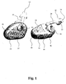
- Fig. 1 shows in perspective from two different angles, a hearing aid according to a first embodiment of the present invention, having a housing 10 with an open canal section in the form of a dome-shaped earpiece 12 that is adapted to be positioned in the ear canal 14 of a wearer comfortably fitting the ear canal 14 for retention of the earpiece 12 in the ear of the wearer.
- the earpiece 12 has an output port 16 for emission of sound towards the eardrum of the wearer.
- the earpiece 12 further has vents 22 that allow sounds outside and within the ear to pass through the ear canal through the earpiece 12 thereby substantially eliminating the occlusion effect when the earpiece 12 is inserted into the ear canal of the wearer.
- the earpiece 12 material may be a soft elastomer, such as silicone rubber or other soft plastic.
- the earpiece 12 material preferably has a durometer of about 30 Shore A.
- the housing 10 further comprises an outer ear section 24 that is connected to the earpiece 12 for accommodation of hearing aid components and adapted for positioning at the concha 26 of the ear during use.
- the outer ear section 24 is manufactured in two parts 40, 42 and has an opening 44 extending through the outer ear section 24 facilitating communication between the ear canal and the surroundings of the wearer.
- a battery lid 46 is provided at an end of the outer ear section 24.
- the battery lid 46 has a compartment accommodating the battery. The battery compartment swings out of the outer ear section 24 when the battery lid is opened whereby the battery may be exchanged with a new battery.
- the outer ear section 24 and the earpiece 12 are interconnected with a substantially rigid sound tube 20.
- the sound tube 20 provides a sound propagation path for sound signals emitted by a receiver (not shown) positioned in the outer ear section 24 of the hearing aid 10 to the output port 16 at the end of the earpiece 12 for transmission of the sound to the eardrum (not shown) in the ear canal 14.
- the sound tube 20 is flexible in a direction perpendicular to the longitudinal extension of the tube 20; however, the tube 20 is substantially rigid, i.e. substantially not flexible (compressible or extendable), along its longitudinal direction thereby providing retention of the earpiece 12 in the ear canal 14 of the wearer.
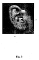
- the transverse flexibility of the tube 20 facilitates insertion of the earpiece 12 in the ear canal 14 and the rigidity of the tube 20 along its longitudinal extension will prevent the earpiece 12 from falling out of the ear canal 14 when the outer ear section is positioned at the concha as shown in Fig. 3 .
- the vent 22 is very short, namely equal to the thickness of the wall of the earpiece 12 and has a large cross-section whereby the occlusion effect is substantially eliminated.
- the outer ear section 24 accommodates the hearing aid components (not shown), such as the microphone(s), amplifier, battery, controls, electrical contacts and connectors, etc.
- Fig. 2 shows a second embodiment similar to the embodiment shown in Fig. 1 , however, with a different earpiece 12 shown in more detail in Figs. 4 - 6 .
- the illustrated second embodiment includes a substantially rigid sound tube 20 identical to the sound tube described in relation to Fig. 1 .
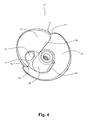
- Figs. 4 - 6 show the earpiece 12 of the embodiment shown in Fig. 2 in more detail.
- This earpiece 12 has two sidewalls 51, 52 extending from a base 53.
- the sidewall 51 has edges 54 and is somewhat smaller, i.e. the sidewall 51 extends along a shorter part of the circumference of the base, than sidewall 52, which has edges 56.
- the sidewalls 51, 52 form a conical sidewall.
- the smaller sidewall 51 is positioned so that its edges 54 may move relative to the edges 56 within the larger sidewall 52 when pressure is applied to (or released from) the sidewalls when the earpiece 12 is accommodated in a user's ear canal.
- Both sidewalls 51, 52 have rounded transition sections 55, 57 between the edges 54, 56 and the outer rim of the sidewalls 51, 52. This reduces the risk of collision between the edges 54, 56 in comparison to e.g. sidewalls with simple sharp corners.
- a sound tube connector 58 may be provided on the base 53 above the output port (not shown) in the base 53 through which sound provided by a sound tube (not shown) may be injected into the ear canal of the user.
- a protrusion 59 may be provided on the side of the connector 58 fitting a corresponding recess in the sound tube whereby the sound tube may be connected to the earpiece in a predetermined angular orientation.
- a vent 22 is provided in the base 53.
- the outer sidewall 52 is thinner than the inner sidewall 51 in the regions close to the respective edges 56 and 54. Therefore, the outer wall will tend to be softer and more flexible in the vicinity of the edges 56 than the inner wall in the corresponding regions.
- the rigidness of the inner sidewall 51 will provide an outward pressure on the overlapping part of the outer sidewall 52 in the direction of the ear canal surface.
- the flexibility of the outer sidewall 52 at the same time provides close contact between itself and both of the inner sidewall 51 and the surface of the ear canal. Thereby, undesired leaks are prevented along the edges 54, 56 of the sidewalls 51, 52 and a close and tight fit in the ear canal is provided.
- the inner wall 51 is thinnest, and therefore most flexible, in the part about midway between the edges 54. This further enhances the above effect, that the inner wall 51 will provide a pressure on the overlapping part of the outer wall 52.
- the outer wall 52 has its thickest section about halfway between its edges 56.
- the thinnest parts of the sidewalls 51, 52 are preferably about half the thickness of the thickest parts.
- the thinnest parts may thus have a thickness in the range of 0.05 mm to 0.5 mm, such as in the range of 0.1 mm to 0.45 mm, such as in the range of 0.15 mm to 0.4 mm, such as in the range of 0.2 mm to 0.35 mm, such as in the range of 0.25 mm to 0.3 mm.
- the thickest parts may have a thickness in the range of 0.1 mm to 1.0 mm, such as in the range of 0.2 mm to 0.9 mm, such as in the range of 0.3 mm to 0.8 mm, such as in the range of 0.4 mm to 0.7 mm, such as in the range of 0.5 mm to 0.6 mm.
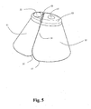
- Fig. 5 shows a recess 60 provided in the outward facing surface of the base 53.
- This recess 60 extends across the oval base 53, thus dividing the base 53 into two sections, one containing the vent 22, and another containing the output port 16 for emission of sound into the user's ear canal.
- the recess 60 functions as a hinge, so that a force that is exerted upon the sidewalls 51, 52 will cause the two sections of the base 53 to bend along the recess 60. Thereby, the base 53 is exposed to less stress, and deformation of the vent opening 22 is avoided.
- the earpiece When the earpiece is inserted into a user's ear canal, pressure is applied to the sidewalls. This will cause the edges to move so that the overlap increases and the circumference of the sidewall decreases correspondingly. The pressure applied to the sidewall by the user's ear canal will provide close contact between the overlapping parts of the sidewalls so that no leaks occur along the edges of the sidewall.
- the illustrated earpiece fits a large number of users while providing a high level of comfort.
- Fig. 6 shows an exemplary embodiment of the invention, wherein a vent 22 is provided as a short tube 56 parallel to and integral with a sound tube connector for receiving and holding the sound tube 20.
- this vent 22, 56 may function as an acoustic filter, such as a low pass filter.
- the earpieces illustrated in Figs. 4-6 may provide venting even without a vent 22 in the base 53. This is believed to be due to the walls 51, 52, at least at the edges 54, 56, being sufficiently thin to be transparent to sound so that sound propagates through the earpiece in the ear canal substantially without attenuation whereby the user does not experience the occlusion effect.
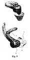
- Figs. 7 and 9 show in perspective from two different angles, a hearing aid according to a third and a fourth embodiment, respectively, of the present invention, having a housing 10 with an open canal section in the form of a dome-shaped earpiece 12 that is adapted to be positioned in the ear canal 14 of a wearer comfortably fitting the ear canal 14 for retention of the earpiece 12 in the ear of the wearer.
- the earpiece 12 has an output port 16 for emission of sound towards the eardrum of the wearer.
- the earpiece 12 further has vents 22 that allow sounds outside and within the ear to pass through the ear canal through the earpiece 12 thereby substantially eliminating the occlusion effect when the earpiece 12 is inserted into the ear canal of the wearer.
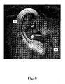
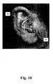
- the housing 10 further comprises an outer ear section 24 that is connected to the earpiece 12 for accommodation of hearing aid components and adapted for positioning at the concha 26 of the ear during use as shown in Figs. 8 and 10 , respectively.
- the outer ear section 24 further comprises a helix section 28 that is adapted to be positioned in the helix 30 of the ear of the wearer and that is mechanically interconnected with the outer ear section 24 with a bridge section 32.
- the helix section 28, the bridge section 32 and the outer ear section 24 form separate units that are manufactured in separate pieces.
- Positioning of the microphone(s) of the hearing aid in the helix section 28 creates an increased distance between the microphone(s) and the output port 16 as compared to the corresponding distance in conventional ITE and CIC hearing aid whereby feedback is diminished.
- the outer ear section 24 is manufactured in two parts 40, 42.
- a battery lid 46 is provided at an end of the outer ear section 24.
- the battery lid 46 has a compartment accommodating the battery. The battery compartment swings out of the outer ear section 24 when the battery lid is opened whereby the battery may be exchanged with a new battery.
- the outer ear section 24 and the earpiece 12 are interconnected with a substantially rigid sound tube 20.
- the sound tube 20 provides a sound propagation path for sound signals emitted by a receiver (not shown) positioned in the outer ear section 24 of the hearing aid 10 to the output port 16 at the end of the earpiece 12 for transmission of the sound to the eardrum (not shown) in the ear canal 14.
- the sound tube 20 is flexible in a direction perpendicular to the longitudinal extension of the tube 20; however, the tube 20 is substantially rigid, i.e. substantially not flexible (compressible or extendable), along its longitudinal direction thereby providing retention of the earpiece 12 in the ear canal 14 of the wearer.
- the transverse flexibility of the tube 20 facilitates insertion of the earpiece 12 in the ear canal 14 and the rigidity of the tube 20 along its longitudinal extension will prevent the earpiece 12 from falling out of the ear canal 14 when the outer ear section is positioned at the outer ear in front of the pinna at the concha and helix as shown in Figs. 8 and 10 .
- the outer ear section 24 accommodates the hearing aid components (not shown), such as the microphone(s), amplifier, battery, controls, electrical contacts and connectors, etc.
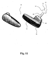
- Fig. 11 shows in perspective from two different angles, a hearing aid according to a fifth embodiment of the present invention, having a housing 10 with an open canal section in the form of a dome-shaped earpiece 12 that is adapted to be positioned in the ear canal 14 of a wearer comfortably fitting the ear canal 14 for retention of the earpiece 12 in the ear of the wearer.
- the earpiece 12 has an output port 16 for emission of sound towards the eardrum of the wearer.
- the earpiece 12 further has vents 22 that allow sounds outside and within the ear to pass through the ear canal through the earpiece 12 thereby substantially eliminating the occlusion effect when the earpiece 12 is inserted into the ear canal of the wearer.
- the housing 10 further comprises an outer ear section 24 that is connected to the earpiece 12 for accommodation of hearing aid components and adapted for positioning at the concha 26 of the ear during use.
- the outer ear section 24 further has a protrusion 48 that fits in the space between the tragus 13 and anti-tragus 15 of a human ear for retention of the outer earpiece 24.
- the outer ear section 24 is manufactured in two parts 40, 42 and has an opening 44 extending through the outer ear section 24 facilitating communication between the ear canal and the surroundings of the wearer.
- a battery lid 46 is provided at an end of the outer ear section 24.
- the battery lid 46 has a compartment accommodating the battery. The battery compartment swings out of the outer ear section 24 when the battery lid is opened whereby the battery may be exchanged with a new battery.
- the outer ear section 24 and the earpiece 12 are interconnected with a substantially rigid sound tube 20.
- the sound tube 20 provides a sound propagation path for sound signals emitted by a receiver (not shown) positioned in the outer ear section 24 of the hearing aid 10 to the output port 16 at the end of the earpiece 12 for transmission of the sound to the eardrum (not shown) in the ear canal 14.
- the sound tube 20 is flexible in a direction perpendicular to the longitudinal extension of the tube 20; however, the tube 20 is substantially rigid, i.e. substantially not flexible (compressible or extendable), along its longitudinal direction thereby providing retention of the earpiece 12 in the ear canal 14 of the wearer.
- the transverse flexibility of the tube 20 facilitates insertion of the earpiece 12 in the ear canal 14 and the rigidity of the tube 20 along its longitudinal extension will prevent the earpiece 12 from falling out of the ear canal 14 when the outer ear section is positioned at the outer ear in front of the pinna as shown in Fig. 12 .
- the outer ear section 24 accommodates the hearing aid components (not shown), such as the microphone(s), amplifier, battery, controls, electrical contacts and connectors, etc.
- the earpiece of the embodiment shown in Figs. 7 and 11 may be substituted with one of the earpieces of Figs. 4 - 6 .
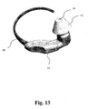
- Fig. 13 shows in perspective, a hearing aid according to a sixth embodiment of the present invention, having a housing 10 with an open canal section shown in Figs. 4 - 6 that is adapted to be positioned in the ear canal 14 of a wearer comfortably fitting the ear canal 14 for retention of the earpiece 12 in the ear of the wearer.
- the earpiece 12 has an output port 16 for emission of sound towards the eardrum of the wearer.
- the earpiece 12 further has a vent 22 (not shown) that allows sounds outside and within the ear to pass through the ear canal through the earpiece 12 thereby substantially eliminating the occlusion effect when the earpiece 12 is inserted into the ear canal of the wearer.
- the housing 10 further comprises an outer ear section 24 that is connected to the earpiece 12 for accommodation of hearing aid components and adapted for positioning at the outer ear in front of the pinna during use as shown in Fig. 14 .
- the outer ear section 24 further comprises a bow 49 that is adapted to be positioned behind the pinna like spectacles and that is mechanically interconnected with the outer ear section 24.
- the bow 49 and the outer ear section 24 form separate units that are manufactured in separate pieces. The bow 49 assists in retaining the housing 10 at the outer ear in front of the wearer's pinna during use.
- the outer ear section 24 and the earpiece 12 are interconnected with a substantially rigid sound tube 20 (not visible).
- the sound tube 20 provides a sound propagation path for sound signals emitted by a receiver (not shown) positioned in the outer ear section 24 of the hearing aid 10 to the output port 16 at the end of the earpiece 12 for transmission of the sound to the eardrum (not shown) in the ear canal 14.
- the sound tube 20 is flexible in a direction perpendicular to the longitudinal extension of the tube 20; however, the tube 20 is substantially rigid, i.e. substantially not flexible (compressible or extendable), along its longitudinal direction thereby providing retention of the earpiece 12 in the ear canal 14 of the wearer.
- the transverse flexibility of the tube 20 facilitates insertion of the earpiece 12 in the ear canal 14 and the rigidity of the tube 20 along its longitudinal extension will prevent the earpiece 12 from falling out of the ear canal 14 when the outer ear section is positioned at the outer ear in front of the pinna at the concha and helix as shown in Fig. 14 .
- the outer ear section 24 accommodates the hearing aid components (not shown), such as the microphone(s), amplifier, battery, controls, electrical contacts and connectors, etc.
- the earpiece of the embodiment shown in Figs. 13 and 14 may be substituted with the dome 12 shown in Fig. 7 .
Landscapes
- Engineering & Computer Science (AREA)
- Physics & Mathematics (AREA)
- Acoustics & Sound (AREA)
- Signal Processing (AREA)
- Manufacturing & Machinery (AREA)
- Health & Medical Sciences (AREA)
- General Health & Medical Sciences (AREA)
- Neurosurgery (AREA)
- Otolaryngology (AREA)
- Headphones And Earphones (AREA)
- Telephone Set Structure (AREA)
Claims (11)
- Am Ohr zu tragendes Hörgerät mit einem Gehäuse (10), welches ein Mikrofon zur Umwandlung von Schall in ein Audiosignal, einen Signalprozessor zur Verarbeitung des Audiosignals zu einem einen Hördefekt kompensierenden Audiosignal und einen an einen Ausgang des Signalprozessors angeschlossenen Empfänger zur Umwandlung des verarbeiteten kompensierten Audiosignals in ein Schallsignal aufnimmt, welches Gehäuse aufweist
einen ein offenes und flexibles in Standardgrößen hergestelltes Ohrpassstück umfassenden Kanalabschnitt, welches Ohrpassstück zum Einstecken in den Ohrkanal eines Trägers angepasst ist und eine kurze Entlüftung aufweist, deren Längsausdehnung kürzer ist als die Längsausdehnung des Ohrpassstücks, und einen Ausgangsanschluss zur Abgabe von Schall in Richtung des Trommelfells des Trägers beim Einsatz in den Ohrkanal aufweist, und einen das Mikrofon aufnehmenden und zur Positionierung vor dem Ohr während der Verwendung angepassten äußeren Ohrabschnitt (24) und ein im Wesentlichen in seiner Längsrichtung starres und senkrecht dazu flexibles und den äußeren Ohrabschnitt mit dem Kanalabschnitt zur Übertragung eines Schallsignals vom äußeren Ohrabschnitt an den Kanalabschnitt verbindendes Schallrohr (20), und welcher äußere Ohrabschnitt (24) den Ohrkanal nicht behindert, wo er sich gegenüber dem äußeren Ohr öffnet, so dass der durch den Kanalabschnitt bereitgestellte Entlüftungseffekt wirksam bleibt. - Hörgerät nach Anspruch 1, welches Hörgerät außerdem ein System für Rückkopplungsunterdrückung umfasst.
- Hörgerät nach Anspruch 1 oder 2, welches Hörgerät außerdem eine mit dem offenen Kanalabschnitt verbundene elastische Faser zum Anliegen an einer Fläche des äußeren Ohrs umfasst, wenn der offene Kanalabschnitt im Ohr eingesetzt worden ist, wobei eine Aufrechterhaltung des offenen Kanalabschnitts im Ohrkanal des Benutzers vorgesehen ist.
- Hörgerät nach irgendeinem der vorhergehenden Ansprüche, wobei das äußere Ohr außerdem einen Helixabschnitt umfasst, welcher dazu angepasst ist, in der Helix des Ohrs des Trägers positioniert zu werden, und welcher mechanisch mit dem äußeren Ohrabschnitt durch einen Brückenabschnitt verbunden ist.
- Hörgerät nach irgendeinem der vorhergehenden Ansprüche, wobei das Schallrohr für Übertragung von Schall vom im äußeren Ohrabschnitt positionierten Empfänger an den Ausgangsanschluss des offenen Kanalabschnitts vorgesehen ist.
- Hörgerät nach irgendeinem der Ansprüche 1-4, wobei das Schallrohr für die Übertragung von elektrischen Signalen vom Ausgang des im äußeren Ohrabschnitt positionierten Signalprozessors an den im Kanalabschnitt positionierten Empfänger zur Abgabe von Schall durch den Ausgangsanschluss des Kanalabschnitts vorgesehen ist.
- Hörgerät nach irgendeinem der vorhergehenden Ansprüche, wobei das flexible Ohrpassstück die Form einer Haube aufweist.
- Hörgerät nach irgendeinem der vorhergehenden Ansprüche, wobei das flexible Ohrpassstück eine Basis und zumindest eine an der Basis befestigte und eine Kante aufweisende Seitenwand umfasst, welche Kante sich im Wesentlichen von der Basis zu einer Öffnung des Ohrpassstücks erstreckt, wobei die Breite der Öffnung in den Ohrkanal des Benutzers eingepasst ist.
- Hörgerät nach Anspruch 8, wobei das flexible Ohrpassstück eine erste und eine zweite Seitenwand aufweist, von denen jede eine sich von angrenzenden Teilen der Basis zur Öffnung erstreckende Kante aufweist.
- Hörgerät nach Anspruch 9, wobei das flexible Ohrpassstück ein Lüften durch zumindest eine der Seitenwände bereitstellt, welche zumindest an den Kanten ausreichend dünn ist, um gegenüber dem Schall transparent zu sein, wobei eine Schallausbreitung durch das Ohrpassstück im Ohrkanal im Wesentlichen ohne Schwächung ermöglicht wird, wobei der Benutzer dem Abschließungseffekt nicht ausgesetzt ist.
- Hörgerät nach irgendeinem der vorhergehenden Ansprüche, wobei das flexible Ohrpassstück eine Entlüftungsöffnung aufweist, und die Längsausdehnung der Entlüftung der Dicke einer Wand des Kanalabschnitts an der Entlüftungsöffnung gleich ist.
Applications Claiming Priority (3)
| Application Number | Priority Date | Filing Date | Title |
|---|---|---|---|
| US70425505P | 2005-08-01 | 2005-08-01 | |
| DKPA200501105 | 2005-08-01 | ||
| PCT/EP2006/064900 WO2007014950A2 (en) | 2005-08-01 | 2006-08-01 | A hearing device with an open earpiece having a short vent |
Publications (2)
| Publication Number | Publication Date |
|---|---|
| EP1913793A2 EP1913793A2 (de) | 2008-04-23 |
| EP1913793B1 true EP1913793B1 (de) | 2010-10-13 |
Family
ID=37125572
Family Applications (1)
| Application Number | Title | Priority Date | Filing Date |
|---|---|---|---|
| EP06792634A Not-in-force EP1913793B1 (de) | 2005-08-01 | 2006-08-01 | Hörgerät mit offenem ohrpassstück mit kurzer entlüftung |
Country Status (4)
| Country | Link |
|---|---|
| US (1) | US8792663B2 (de) |
| EP (1) | EP1913793B1 (de) |
| JP (1) | JP4966304B2 (de) |
| WO (1) | WO2007014950A2 (de) |
Families Citing this family (60)
| Publication number | Priority date | Publication date | Assignee | Title |
|---|---|---|---|---|
| JP4966304B2 (ja) | 2005-08-01 | 2012-07-04 | ジーエヌ リザウンド エー/エス | 短い通気孔を有する開放耳当てを備えた聴取装置 |
| US8948430B2 (en) * | 2006-06-23 | 2015-02-03 | Gn Resound A/S | Hearing aid with an elongate member |
| US8249287B2 (en) | 2010-08-16 | 2012-08-21 | Bose Corporation | Earpiece positioning and retaining |
| US10291980B2 (en) | 2006-06-30 | 2019-05-14 | Bose Corporation | Earpiece positioning and retaining |
| US7856111B2 (en) | 2006-10-04 | 2010-12-21 | Siemens Audiologische Technik Gmbh | Hearing aid with sound tube serving for retention in concha |
| WO2009004395A1 (fr) * | 2007-06-29 | 2009-01-08 | Frame S.A. | Dispositif electro-acoustique auriculaire |
| CN107426659A (zh) | 2007-12-27 | 2017-12-01 | Gn瑞声达A/S | 具有由印刷电路板形成的壁的听力器械 |
| EP2076064B1 (de) * | 2007-12-27 | 2017-04-26 | Oticon A/S | Hörvorrichtung mit Hörgeräte-Otoplastik und Ausgangsmodul |
| DK2238772T3 (en) * | 2007-12-27 | 2017-01-09 | Gn Resound As | The modular hearing device |
| US8989418B2 (en) * | 2008-02-27 | 2015-03-24 | Linda D. Dahl | Ear device for improved fit and sound |
| US9716935B2 (en) * | 2008-02-27 | 2017-07-25 | Linda D. Dahl | Sound system with ear device with improved fit and sound |
| US9445183B2 (en) | 2008-02-27 | 2016-09-13 | Linda D. Dahl | Sound system with ear device with improved fit and sound |
| EP2117258A1 (de) | 2008-05-07 | 2009-11-11 | Cochlear Limited | Kabellängeneinstellung in Hörgeräten |
| JP2011524703A (ja) * | 2008-10-10 | 2011-09-01 | ヴェーデクス・アクティーセルスカプ | 補聴器のイヤピース用保持モジュール |
| WO2009153221A2 (en) * | 2009-06-12 | 2009-12-23 | Phonak Ag | Hearing system comprising an earpiece |
| WO2009115618A2 (en) | 2009-06-30 | 2009-09-24 | Phonak Ag | Hearing device with a vent extension and method for manufacturing such a hearing device |
| GB0922610D0 (en) * | 2009-12-23 | 2010-02-10 | B & W Group Ltd | Earphone |
| EP2469890B1 (de) * | 2010-12-23 | 2015-06-24 | GN ReSound A/S | BTE-Hörgerät mit länglichem Sicherungselement |
| US8616214B2 (en) | 2011-04-06 | 2013-12-31 | Kimberly-Clark Worldwide, Inc. | Earplug having a resilient core structure |
| US8737669B2 (en) * | 2011-07-28 | 2014-05-27 | Bose Corporation | Earpiece passive noise attenuating |
| CA2871281A1 (en) | 2012-02-23 | 2013-08-29 | Aria Innovations, Inc. | Adjustable securing mechanism for a space access device |
| US8976994B2 (en) | 2012-06-20 | 2015-03-10 | Apple Inc. | Earphone having an acoustic tuning mechanism |
| US9712905B2 (en) | 2012-06-20 | 2017-07-18 | Apple Inc. | Headsets with non-occluding earbuds |
| US8971561B2 (en) | 2012-06-20 | 2015-03-03 | Apple Inc. | Earphone having a controlled acoustic leak port |
| EP2690883B1 (de) | 2012-07-27 | 2017-10-11 | Freebit AS | Sub-Tragus Gehöreinheit |
| US9258663B2 (en) | 2012-09-07 | 2016-02-09 | Apple Inc. | Systems and methods for assembling non-occluding earbuds |
| US8798283B2 (en) * | 2012-11-02 | 2014-08-05 | Bose Corporation | Providing ambient naturalness in ANR headphones |
| CN103327435A (zh) * | 2013-07-15 | 2013-09-25 | 江苏贝泰福医疗科技有限公司 | 耳内受话耳背式助听器的非分离式可变形耳钩 |
| US9479859B2 (en) | 2013-11-18 | 2016-10-25 | 3M Innovative Properties Company | Concha-fit electronic hearing protection device |
| US9462366B2 (en) | 2014-03-27 | 2016-10-04 | Bose Corporation | Earpieces having flexible flaps |
| EP2928203A1 (de) * | 2014-04-03 | 2015-10-07 | Oticon A/s | Hörgerät |
| CN107079226A (zh) * | 2014-10-09 | 2017-08-18 | 索诺亚公司 | 助听装置 |
| EP3248394A4 (de) * | 2015-01-19 | 2018-09-12 | 3M Innovative Properties Company | Gehörschutzvorrichtung mit gewundenem schalltrichter |
| EP3082347B1 (de) | 2015-04-17 | 2017-12-27 | Skullcandy, Inc. | Ohrinterner kopfhörer mit befestigungsteilen |
| WO2017004039A1 (en) * | 2015-07-02 | 2017-01-05 | K-Rain Manufacturing Corporation | External ear insert for hearing enhancement |
| EP3318071A4 (de) * | 2015-07-02 | 2018-12-12 | K-rain Manufacturing Corp. | Äusserer ohreinsatz zur gehörverbesserung |
| FI126466B (en) | 2015-11-24 | 2016-12-30 | Qon Oy | Wireless noise canceling earplug |
| CN105430550B (zh) * | 2015-12-29 | 2019-01-08 | 青岛歌尔声学科技有限公司 | 一种开放式耳机 |
| US11388501B2 (en) | 2016-09-01 | 2022-07-12 | Zoku Limited | Earpiece with actuator |
| GB2553518B (en) * | 2016-09-01 | 2022-03-09 | Third Skin Ltd | An earpiece |
| DK3313097T3 (da) | 2016-10-19 | 2020-10-19 | Sonion Nederland Bv | An ear bud or dome |
| USD808934S1 (en) * | 2016-12-15 | 2018-01-30 | Echo Box Audio, Llc | Earbud |
| US11323794B2 (en) * | 2017-03-20 | 2022-05-03 | Buderflys Technologies, Inc. | Personal hearing device |
| CN108966065A (zh) * | 2017-05-19 | 2018-12-07 | 瑞铭科技股份有限公司 | 耳机头结构、耳机套结构及其耳道式耳机装置 |
| CN110679160B (zh) * | 2017-06-16 | 2021-07-30 | 唯听助听器公司 | 一种耳承以及应用该耳承的耳塞和助听器 |
| DE102017211668A1 (de) * | 2017-07-07 | 2019-01-10 | Sivantos Pte. Ltd. | Verfahren zum Herstellen eines Gehäuseteils einer Hörvorrichtung, Gehäuseteil für eine Hörvorrichtung und Hörvorrichtung |
| DE102018107195B3 (de) * | 2018-02-05 | 2019-02-14 | Paul Gregor Junke | Universal Silikon-Softadapter für Hörgeräte |
| WO2020005818A1 (en) * | 2018-06-26 | 2020-01-02 | Dolby Laboratories Licensing Corporation | In-ear radio frequency antenna |
| DK3664474T3 (da) | 2018-12-04 | 2023-03-27 | Oticon As | Højttaleranordning til høreapparat |
| US11166093B2 (en) | 2019-03-19 | 2021-11-02 | Logitech Europe S.A. | Earphone device support and case |
| EP3726855B1 (de) * | 2019-04-15 | 2021-09-01 | Sonion Nederland B.V. | Persönliches hörgerät mit entlüftungskanal und akustischer trennung |
| WO2020261110A1 (en) * | 2019-06-28 | 2020-12-30 | 3M Innovative Properties Company | Antenna for protective personal equipment |
| US11622215B2 (en) | 2019-12-13 | 2023-04-04 | Sonova Ag | Hearing device assemblies |
| DE102020100391B4 (de) | 2020-01-10 | 2023-12-07 | icarus Technology UG (haftungsbeschränkt) | Einzelohrhörer und Ohrhörer |
| US20230095933A1 (en) * | 2020-02-26 | 2023-03-30 | Starkey Laboratories, Inc. | Ear-wearable hearing device |
| US20210307690A1 (en) * | 2020-04-07 | 2021-10-07 | Nextsense, Inc. | Multi-Body Earpiece |
| US20230179901A1 (en) * | 2020-05-07 | 2023-06-08 | Hearable Labs Ug | Ear worn device |
| USD974038S1 (en) | 2020-12-02 | 2023-01-03 | Logitech Europe S.A. | Earphone case |
| USD1002583S1 (en) | 2020-12-02 | 2023-10-24 | Logitech Europe S.A. | Combined earphone and earphone case |
| USD969772S1 (en) | 2020-12-02 | 2022-11-15 | Logitech Europe S.A. | Earphone |
Family Cites Families (31)
| Publication number | Priority date | Publication date | Assignee | Title |
|---|---|---|---|---|
| GB1173657A (en) * | 1967-05-09 | 1969-12-10 | Emi Ltd | Improvements in or relating to Hearing Aids. |
| US3783201A (en) * | 1970-12-02 | 1974-01-01 | Beltone Electronics Corp | Miniature hearing aid structure |
| US3935401A (en) | 1974-08-29 | 1976-01-27 | Shore Sidney X | Earpiece for acoustic headset |
| US4375016A (en) | 1980-04-28 | 1983-02-22 | Qualitone Hearing Aids Inc. | Vented ear tip for hearing aid and adapter coupler therefore |
| JPS57171398U (de) * | 1981-04-20 | 1982-10-28 | ||
| JPS60180200U (ja) * | 1984-05-10 | 1985-11-29 | ソニー株式会社 | 補聴器 |
| US5201007A (en) | 1988-09-15 | 1993-04-06 | Epic Corporation | Apparatus and method for conveying amplified sound to ear |
| US4878560A (en) | 1989-03-16 | 1989-11-07 | Scott Robert T | Earmold |
| US5046580A (en) * | 1990-08-17 | 1991-09-10 | Barton James I | Ear plug assembly for hearing aid |
| US5680467A (en) | 1992-03-31 | 1997-10-21 | Gn Danavox A/S | Hearing aid compensating for acoustic feedback |
| DK169958B1 (da) | 1992-10-20 | 1995-04-10 | Gn Danavox As | Høreapparat med kompensation for akustisk tilbagekobling |
| JP2900125B2 (ja) * | 1994-07-22 | 1999-06-02 | リオン株式会社 | 耳せん及びこれを使用した補聴器 |
| DE19504478C2 (de) | 1995-02-10 | 1996-12-19 | Siemens Audiologische Technik | Gehörgangseinsatz für Hörhilfen |
| JP3882211B2 (ja) * | 1995-08-23 | 2007-02-14 | ソニー株式会社 | イヤホン装置 |
| JP4354631B2 (ja) | 1997-07-18 | 2009-10-28 | リザウンド コーポレイション | 耳の後ろに取り付ける補聴器装置 |
| US6498858B2 (en) | 1997-11-18 | 2002-12-24 | Gn Resound A/S | Feedback cancellation improvements |
| DE29810947U1 (de) | 1998-06-18 | 1998-09-17 | Tempa Communication Inc | Ohrhörer für Mobiltelefone, insbesondere Funk- und Autotelefone |
| US6473513B1 (en) * | 1999-06-08 | 2002-10-29 | Insonus Medical, Inc. | Extended wear canal hearing device |
| US6359993B2 (en) * | 1999-01-15 | 2002-03-19 | Sonic Innovations | Conformal tip for a hearing aid with integrated vent and retrieval cord |
| JP4151157B2 (ja) | 1999-05-31 | 2008-09-17 | ソニー株式会社 | イヤホン |
| US7092543B1 (en) | 1999-07-23 | 2006-08-15 | Sarnoff Corporation | One-size-fits-all uni-ear hearing instrument |
| AU2001245678A1 (en) | 2000-03-13 | 2001-09-24 | Sarnoff Corporation | Hearing aid with a flexible shell |
| US7130437B2 (en) | 2000-06-29 | 2006-10-31 | Beltone Electronics Corporation | Compressible hearing aid |
| EP1535489A4 (de) | 2002-07-18 | 2007-01-24 | Insound Medical Inc | Im-kanal-hörgerät mit rohrförmigem einsatz |
| AU2003269847A1 (en) * | 2002-10-16 | 2004-05-04 | Microsound A/S | Hearing prosthesis |
| US7590255B2 (en) | 2003-02-14 | 2009-09-15 | Gn Resound A/S | Retaining member for an earpiece |
| EP1594340B1 (de) * | 2004-05-03 | 2012-05-30 | GN ReSound A/S | Flexible Hörmuschel für ein Hörhilfegerät |
| CN101138273B (zh) * | 2005-03-10 | 2013-03-06 | 唯听助听器公司 | 一种用于助听器的耳塞 |
| JP4966304B2 (ja) | 2005-08-01 | 2012-07-04 | ジーエヌ リザウンド エー/エス | 短い通気孔を有する開放耳当てを備えた聴取装置 |
| NL1030649C2 (nl) * | 2005-12-12 | 2007-06-13 | Exsilent Res Bv | Hoortoestel. |
| US8096383B2 (en) * | 2006-03-21 | 2012-01-17 | Siemens Hearing Instruments Inc. | Tapered vent for a hearing instrument |
-
2006
- 2006-08-01 JP JP2008524515A patent/JP4966304B2/ja not_active Expired - Fee Related
- 2006-08-01 WO PCT/EP2006/064900 patent/WO2007014950A2/en active Application Filing
- 2006-08-01 EP EP06792634A patent/EP1913793B1/de not_active Not-in-force
- 2006-08-01 US US11/997,738 patent/US8792663B2/en active Active
Also Published As
| Publication number | Publication date |
|---|---|
| EP1913793A2 (de) | 2008-04-23 |
| WO2007014950B1 (en) | 2007-08-23 |
| WO2007014950A2 (en) | 2007-02-08 |
| JP2009504045A (ja) | 2009-01-29 |
| US8792663B2 (en) | 2014-07-29 |
| WO2007014950A3 (en) | 2007-07-12 |
| US20090123010A1 (en) | 2009-05-14 |
| JP4966304B2 (ja) | 2012-07-04 |
Similar Documents
| Publication | Publication Date | Title |
|---|---|---|
| EP1913793B1 (de) | Hörgerät mit offenem ohrpassstück mit kurzer entlüftung | |
| US8331593B2 (en) | Hearing aid with a removably connected elongate member | |
| US8885858B2 (en) | Modular hearing instrument | |
| US7899200B2 (en) | Universal-fit hearing device | |
| DK2033486T3 (en) | Hearing aid with a removably connected, elongated member | |
| US9232324B2 (en) | Hearing instrument with a wall formed by a printed circuit board | |
| CN101297593B (zh) | 含有具有短释逸装置的开放式耳塞的听力装置 | |
| EP1535489A1 (de) | Im-kanal-hörgerät mit rohrförmigem einsatz | |
| EP2025202B1 (de) | Universell passendes hörgerät | |
| DK2238773T3 (en) | Hearing aid with a wall formed by a printed circuit board |
Legal Events
| Date | Code | Title | Description |
|---|---|---|---|
| PUAI | Public reference made under article 153(3) epc to a published international application that has entered the european phase |
Free format text: ORIGINAL CODE: 0009012 |
|
| 17P | Request for examination filed |
Effective date: 20080303 |
|
| AK | Designated contracting states |
Kind code of ref document: A2 Designated state(s): AT BE BG CH CY CZ DE DK EE ES FI FR GB GR HU IE IS IT LI LT LU LV MC NL PL PT RO SE SI SK TR |
|
| GRAP | Despatch of communication of intention to grant a patent |
Free format text: ORIGINAL CODE: EPIDOSNIGR1 |
|
| GRAS | Grant fee paid |
Free format text: ORIGINAL CODE: EPIDOSNIGR3 |
|
| DAX | Request for extension of the european patent (deleted) | ||
| RAP1 | Party data changed (applicant data changed or rights of an application transferred) |
Owner name: GN RESOUND A/S |
|
| GRAA | (expected) grant |
Free format text: ORIGINAL CODE: 0009210 |
|
| AK | Designated contracting states |
Kind code of ref document: B1 Designated state(s): AT BE BG CH CY CZ DE DK EE ES FI FR GB GR HU IE IS IT LI LT LU LV MC NL PL PT RO SE SI SK TR |
|
| REG | Reference to a national code |
Ref country code: GB Ref legal event code: FG4D |
|
| REG | Reference to a national code |
Ref country code: CH Ref legal event code: EP |
|
| REG | Reference to a national code |
Ref country code: IE Ref legal event code: FG4D |
|
| REF | Corresponds to: |
Ref document number: 602006017560 Country of ref document: DE Date of ref document: 20101125 Kind code of ref document: P |
|
| REG | Reference to a national code |
Ref country code: CH Ref legal event code: NV Representative=s name: PETER RUTZ |
|
| REG | Reference to a national code |
Ref country code: DK Ref legal event code: T3 |
|
| REG | Reference to a national code |
Ref country code: NL Ref legal event code: VDEP Effective date: 20101013 |
|
| LTIE | Lt: invalidation of european patent or patent extension |
Effective date: 20101013 |
|
| PG25 | Lapsed in a contracting state [announced via postgrant information from national office to epo] |
Ref country code: LT Free format text: LAPSE BECAUSE OF FAILURE TO SUBMIT A TRANSLATION OF THE DESCRIPTION OR TO PAY THE FEE WITHIN THE PRESCRIBED TIME-LIMIT Effective date: 20101013 |
|
| PG25 | Lapsed in a contracting state [announced via postgrant information from national office to epo] |
Ref country code: NL Free format text: LAPSE BECAUSE OF FAILURE TO SUBMIT A TRANSLATION OF THE DESCRIPTION OR TO PAY THE FEE WITHIN THE PRESCRIBED TIME-LIMIT Effective date: 20101013 Ref country code: SE Free format text: LAPSE BECAUSE OF FAILURE TO SUBMIT A TRANSLATION OF THE DESCRIPTION OR TO PAY THE FEE WITHIN THE PRESCRIBED TIME-LIMIT Effective date: 20101013 Ref country code: BG Free format text: LAPSE BECAUSE OF FAILURE TO SUBMIT A TRANSLATION OF THE DESCRIPTION OR TO PAY THE FEE WITHIN THE PRESCRIBED TIME-LIMIT Effective date: 20110113 Ref country code: AT Free format text: LAPSE BECAUSE OF FAILURE TO SUBMIT A TRANSLATION OF THE DESCRIPTION OR TO PAY THE FEE WITHIN THE PRESCRIBED TIME-LIMIT Effective date: 20101013 Ref country code: PT Free format text: LAPSE BECAUSE OF FAILURE TO SUBMIT A TRANSLATION OF THE DESCRIPTION OR TO PAY THE FEE WITHIN THE PRESCRIBED TIME-LIMIT Effective date: 20110214 Ref country code: IS Free format text: LAPSE BECAUSE OF FAILURE TO SUBMIT A TRANSLATION OF THE DESCRIPTION OR TO PAY THE FEE WITHIN THE PRESCRIBED TIME-LIMIT Effective date: 20110213 Ref country code: FI Free format text: LAPSE BECAUSE OF FAILURE TO SUBMIT A TRANSLATION OF THE DESCRIPTION OR TO PAY THE FEE WITHIN THE PRESCRIBED TIME-LIMIT Effective date: 20101013 Ref country code: LV Free format text: LAPSE BECAUSE OF FAILURE TO SUBMIT A TRANSLATION OF THE DESCRIPTION OR TO PAY THE FEE WITHIN THE PRESCRIBED TIME-LIMIT Effective date: 20101013 Ref country code: SI Free format text: LAPSE BECAUSE OF FAILURE TO SUBMIT A TRANSLATION OF THE DESCRIPTION OR TO PAY THE FEE WITHIN THE PRESCRIBED TIME-LIMIT Effective date: 20101013 |
|
| PG25 | Lapsed in a contracting state [announced via postgrant information from national office to epo] |
Ref country code: GR Free format text: LAPSE BECAUSE OF FAILURE TO SUBMIT A TRANSLATION OF THE DESCRIPTION OR TO PAY THE FEE WITHIN THE PRESCRIBED TIME-LIMIT Effective date: 20110114 Ref country code: BE Free format text: LAPSE BECAUSE OF FAILURE TO SUBMIT A TRANSLATION OF THE DESCRIPTION OR TO PAY THE FEE WITHIN THE PRESCRIBED TIME-LIMIT Effective date: 20101013 |
|
| PG25 | Lapsed in a contracting state [announced via postgrant information from national office to epo] |
Ref country code: ES Free format text: LAPSE BECAUSE OF FAILURE TO SUBMIT A TRANSLATION OF THE DESCRIPTION OR TO PAY THE FEE WITHIN THE PRESCRIBED TIME-LIMIT Effective date: 20110124 Ref country code: EE Free format text: LAPSE BECAUSE OF FAILURE TO SUBMIT A TRANSLATION OF THE DESCRIPTION OR TO PAY THE FEE WITHIN THE PRESCRIBED TIME-LIMIT Effective date: 20101013 Ref country code: CZ Free format text: LAPSE BECAUSE OF FAILURE TO SUBMIT A TRANSLATION OF THE DESCRIPTION OR TO PAY THE FEE WITHIN THE PRESCRIBED TIME-LIMIT Effective date: 20101013 |
|
| PLBE | No opposition filed within time limit |
Free format text: ORIGINAL CODE: 0009261 |
|
| STAA | Information on the status of an ep patent application or granted ep patent |
Free format text: STATUS: NO OPPOSITION FILED WITHIN TIME LIMIT |
|
| PG25 | Lapsed in a contracting state [announced via postgrant information from national office to epo] |
Ref country code: RO Free format text: LAPSE BECAUSE OF FAILURE TO SUBMIT A TRANSLATION OF THE DESCRIPTION OR TO PAY THE FEE WITHIN THE PRESCRIBED TIME-LIMIT Effective date: 20101013 Ref country code: SK Free format text: LAPSE BECAUSE OF FAILURE TO SUBMIT A TRANSLATION OF THE DESCRIPTION OR TO PAY THE FEE WITHIN THE PRESCRIBED TIME-LIMIT Effective date: 20101013 Ref country code: PL Free format text: LAPSE BECAUSE OF FAILURE TO SUBMIT A TRANSLATION OF THE DESCRIPTION OR TO PAY THE FEE WITHIN THE PRESCRIBED TIME-LIMIT Effective date: 20101013 |
|
| 26N | No opposition filed |
Effective date: 20110714 |
|
| REG | Reference to a national code |
Ref country code: DE Ref legal event code: R097 Ref document number: 602006017560 Country of ref document: DE Effective date: 20110714 |
|
| PG25 | Lapsed in a contracting state [announced via postgrant information from national office to epo] |
Ref country code: IT Free format text: LAPSE BECAUSE OF FAILURE TO SUBMIT A TRANSLATION OF THE DESCRIPTION OR TO PAY THE FEE WITHIN THE PRESCRIBED TIME-LIMIT Effective date: 20101013 |
|
| PG25 | Lapsed in a contracting state [announced via postgrant information from national office to epo] |
Ref country code: MC Free format text: LAPSE BECAUSE OF NON-PAYMENT OF DUE FEES Effective date: 20110831 |
|
| REG | Reference to a national code |
Ref country code: IE Ref legal event code: MM4A |
|
| PG25 | Lapsed in a contracting state [announced via postgrant information from national office to epo] |
Ref country code: IE Free format text: LAPSE BECAUSE OF NON-PAYMENT OF DUE FEES Effective date: 20110801 |
|
| PG25 | Lapsed in a contracting state [announced via postgrant information from national office to epo] |
Ref country code: CY Free format text: LAPSE BECAUSE OF EXPIRATION OF PROTECTION Effective date: 20101013 Ref country code: LU Free format text: LAPSE BECAUSE OF NON-PAYMENT OF DUE FEES Effective date: 20110801 |
|
| PG25 | Lapsed in a contracting state [announced via postgrant information from national office to epo] |
Ref country code: TR Free format text: LAPSE BECAUSE OF FAILURE TO SUBMIT A TRANSLATION OF THE DESCRIPTION OR TO PAY THE FEE WITHIN THE PRESCRIBED TIME-LIMIT Effective date: 20101013 |
|
| PG25 | Lapsed in a contracting state [announced via postgrant information from national office to epo] |
Ref country code: HU Free format text: LAPSE BECAUSE OF FAILURE TO SUBMIT A TRANSLATION OF THE DESCRIPTION OR TO PAY THE FEE WITHIN THE PRESCRIBED TIME-LIMIT Effective date: 20101013 |
|
| REG | Reference to a national code |
Ref country code: FR Ref legal event code: PLFP Year of fee payment: 11 |
|
| REG | Reference to a national code |
Ref country code: FR Ref legal event code: PLFP Year of fee payment: 12 |
|
| REG | Reference to a national code |
Ref country code: FR Ref legal event code: PLFP Year of fee payment: 13 |
|
| REG | Reference to a national code |
Ref country code: CH Ref legal event code: PCAR Free format text: NEW ADDRESS: ALPENSTRASSE 14 POSTFACH 7627, 6302 ZUG (CH) |
|
| REG | Reference to a national code |
Ref country code: DE Ref legal event code: R082 Ref document number: 602006017560 Country of ref document: DE Representative=s name: ZACCO LEGAL RECHTSANWALTSGESELLSCHAFT MBH, DE Ref country code: DE Ref legal event code: R082 Ref document number: 602006017560 Country of ref document: DE Representative=s name: ZACCO PATENTANWALTS- UND RECHTSANWALTSGESELLSC, DE |
|
| PGFP | Annual fee paid to national office [announced via postgrant information from national office to epo] |
Ref country code: FR Payment date: 20210816 Year of fee payment: 16 |
|
| PGFP | Annual fee paid to national office [announced via postgrant information from national office to epo] |
Ref country code: DK Payment date: 20210818 Year of fee payment: 16 Ref country code: GB Payment date: 20210818 Year of fee payment: 16 Ref country code: CH Payment date: 20210818 Year of fee payment: 16 Ref country code: DE Payment date: 20210819 Year of fee payment: 16 |
|
| REG | Reference to a national code |
Ref country code: DE Ref legal event code: R082 Ref document number: 602006017560 Country of ref document: DE Representative=s name: ZACCO LEGAL RECHTSANWALTSGESELLSCHAFT MBH, DE |
|
| REG | Reference to a national code |
Ref country code: DE Ref legal event code: R119 Ref document number: 602006017560 Country of ref document: DE |
|
| REG | Reference to a national code |
Ref country code: DK Ref legal event code: EBP Effective date: 20220831 |
|
| REG | Reference to a national code |
Ref country code: CH Ref legal event code: PL |
|
| GBPC | Gb: european patent ceased through non-payment of renewal fee |
Effective date: 20220801 |
|
| PG25 | Lapsed in a contracting state [announced via postgrant information from national office to epo] |
Ref country code: LI Free format text: LAPSE BECAUSE OF NON-PAYMENT OF DUE FEES Effective date: 20220831 Ref country code: CH Free format text: LAPSE BECAUSE OF NON-PAYMENT OF DUE FEES Effective date: 20220831 |
|
| P01 | Opt-out of the competence of the unified patent court (upc) registered |
Effective date: 20230524 |
|
| PG25 | Lapsed in a contracting state [announced via postgrant information from national office to epo] |
Ref country code: FR Free format text: LAPSE BECAUSE OF NON-PAYMENT OF DUE FEES Effective date: 20220831 Ref country code: DK Free format text: LAPSE BECAUSE OF NON-PAYMENT OF DUE FEES Effective date: 20220831 Ref country code: DE Free format text: LAPSE BECAUSE OF NON-PAYMENT OF DUE FEES Effective date: 20230301 |
|
| PG25 | Lapsed in a contracting state [announced via postgrant information from national office to epo] |
Ref country code: GB Free format text: LAPSE BECAUSE OF NON-PAYMENT OF DUE FEES Effective date: 20220801 |