EP1913253B1 - Fuel injecting device and method for controlling said device - Google Patents
Fuel injecting device and method for controlling said device Download PDFInfo
- Publication number
- EP1913253B1 EP1913253B1 EP06794493A EP06794493A EP1913253B1 EP 1913253 B1 EP1913253 B1 EP 1913253B1 EP 06794493 A EP06794493 A EP 06794493A EP 06794493 A EP06794493 A EP 06794493A EP 1913253 B1 EP1913253 B1 EP 1913253B1
- Authority
- EP
- European Patent Office
- Prior art keywords
- needle
- actuator
- rod
- injection device
- head
- Prior art date
- Legal status (The legal status is an assumption and is not a legal conclusion. Google has not performed a legal analysis and makes no representation as to the accuracy of the status listed.)
- Active
Links
- 239000000446 fuel Substances 0.000 title claims abstract description 14
- 238000000034 method Methods 0.000 title claims abstract description 6
- 239000000463 material Substances 0.000 claims abstract description 16
- 230000005284 excitation Effects 0.000 claims abstract description 14
- 239000011263 electroactive material Substances 0.000 claims abstract description 5
- 238000002347 injection Methods 0.000 claims description 29
- 239000007924 injection Substances 0.000 claims description 29
- 230000005291 magnetic effect Effects 0.000 claims description 6
- 230000000737 periodic effect Effects 0.000 claims description 5
- 239000003302 ferromagnetic material Substances 0.000 claims description 4
- 230000003534 oscillatory effect Effects 0.000 claims description 4
- 238000013016 damping Methods 0.000 claims description 3
- 230000003213 activating effect Effects 0.000 claims 1
- 238000002485 combustion reaction Methods 0.000 description 6
- 238000006073 displacement reaction Methods 0.000 description 6
- 230000010355 oscillation Effects 0.000 description 6
- 230000015572 biosynthetic process Effects 0.000 description 3
- 230000000694 effects Effects 0.000 description 3
- 229910000831 Steel Inorganic materials 0.000 description 2
- RTAQQCXQSZGOHL-UHFFFAOYSA-N Titanium Chemical compound [Ti] RTAQQCXQSZGOHL-UHFFFAOYSA-N 0.000 description 2
- 230000006835 compression Effects 0.000 description 2
- 238000007906 compression Methods 0.000 description 2
- 239000000470 constituent Substances 0.000 description 2
- 239000010959 steel Substances 0.000 description 2
- 239000010936 titanium Substances 0.000 description 2
- 229910052719 titanium Inorganic materials 0.000 description 2
- WFKWXMTUELFFGS-UHFFFAOYSA-N tungsten Chemical compound [W] WFKWXMTUELFFGS-UHFFFAOYSA-N 0.000 description 2
- 239000010937 tungsten Substances 0.000 description 2
- 229910052721 tungsten Inorganic materials 0.000 description 2
- 229910001329 Terfenol-D Inorganic materials 0.000 description 1
- 238000006243 chemical reaction Methods 0.000 description 1
- 230000005489 elastic deformation Effects 0.000 description 1
- 239000000696 magnetic material Substances 0.000 description 1
- 238000003032 molecular docking Methods 0.000 description 1
- 210000002445 nipple Anatomy 0.000 description 1
- 230000036316 preload Effects 0.000 description 1
- 230000035939 shock Effects 0.000 description 1
Images
Classifications
-
- F—MECHANICAL ENGINEERING; LIGHTING; HEATING; WEAPONS; BLASTING
- F02—COMBUSTION ENGINES; HOT-GAS OR COMBUSTION-PRODUCT ENGINE PLANTS
- F02M—SUPPLYING COMBUSTION ENGINES IN GENERAL WITH COMBUSTIBLE MIXTURES OR CONSTITUENTS THEREOF
- F02M69/00—Low-pressure fuel-injection apparatus ; Apparatus with both continuous and intermittent injection; Apparatus injecting different types of fuel
- F02M69/04—Injectors peculiar thereto
- F02M69/041—Injectors peculiar thereto having vibrating means for atomizing the fuel, e.g. with sonic or ultrasonic vibrations
-
- F—MECHANICAL ENGINEERING; LIGHTING; HEATING; WEAPONS; BLASTING
- F02—COMBUSTION ENGINES; HOT-GAS OR COMBUSTION-PRODUCT ENGINE PLANTS
- F02M—SUPPLYING COMBUSTION ENGINES IN GENERAL WITH COMBUSTIBLE MIXTURES OR CONSTITUENTS THEREOF
- F02M2200/00—Details of fuel-injection apparatus, not otherwise provided for
- F02M2200/21—Fuel-injection apparatus with piezoelectric or magnetostrictive elements
-
- F—MECHANICAL ENGINEERING; LIGHTING; HEATING; WEAPONS; BLASTING
- F02—COMBUSTION ENGINES; HOT-GAS OR COMBUSTION-PRODUCT ENGINE PLANTS
- F02M—SUPPLYING COMBUSTION ENGINES IN GENERAL WITH COMBUSTIBLE MIXTURES OR CONSTITUENTS THEREOF
- F02M51/00—Fuel-injection apparatus characterised by being operated electrically
- F02M51/06—Injectors peculiar thereto with means directly operating the valve needle
- F02M51/0603—Injectors peculiar thereto with means directly operating the valve needle using piezoelectric or magnetostrictive operating means
Definitions
- the invention relates to a fuel injection device, in particular for an internal combustion engine, and to its control method.
- an injection device comprising a tubular body in which a needle is shown.
- the needle is terminated by a valve head with a seat carried by the end of the tubular body.
- Pressurized fuel feeds the inside of the tubular body and is stopped by the valve.
- the needle has a longitudinal housing in which is placed an electroactive material. When the electroactive material is excited, it elongates, causing the elastic elongation of the needle and thus the detachment of the head relative to the seat.
- the valve is then opened and the fuel passes between the seat and the head to be injected into a combustion chamber.
- the response time to operate the maximum lift of the valve is very short, typically less than 50 microseconds. It is therefore possible to control the degree of opening of the valve substantially at each moment during the injection phase. This controls the instantaneous flow of fuel and the formation of fuel droplets.
- the element electro-active is in the immediate vicinity of the head.
- the electro-active element can be raised to temperatures likely to degrade its operation.
- its location near the nose of the injector can cause congestion problems.
- the subject of the invention is a fuel injection device comprising a cylindrical body, a needle whose one end comprises a head forming a valve on a seat carried by one end of the cylindrical body, an actuator with electro-magnetic material. -Active, the actuator having a bar and being able to cause a displacement of the head to open the valve, a flyweight extending the bar, a prestressing device holding the needle and the flyweight bearing against opposite ends of the bar.
- the needle extends coaxially with the cylindrical body in the form of a rigid bar, the needle being able to enter into axial resonance when it is subjected by the actuator to axial pulses at a determined excitation frequency, thus superimposing a vibratory movement of the head to the overall motion of the needle.
- the length of the bar allows to place the actuator in the body of the device away from the head, and therefore to be less exposed to the heat of the combustion chamber.
- the excitation frequency is chosen close to a self-mode frequency of the needle so as to obtain a resonance phenomenon by successions of compression and extensions of the needle in the axial direction. Furthermore, the fact of being able to resonate the bar in the axial direction of the device makes it possible to obtain a mode of displacement of the head in the axial direction at the chosen excitation frequency.
- the chosen frequency is for example such that the oscillation period is much shorter than the duration of an injection phase. Oscillations of the head can modulate the fuel flow and thus control the formation of very fine fuel droplets.
- the excitation frequency is in a range extending from 10 to 30 kHz. It is thus possible to obtain the formation of very fine droplets during the injection phase.
- the bar is made of magnetostrictive material and is surrounded by a coil capable of creating a magnetic field in the bar.
- a coil capable of creating a magnetic field in the bar.
- the needle When such material is subjected to a magnetic field, it undergoes an elongation which is transmitted to the needle.
- the needle then moves axially in the direction of an opening of the valve. According to the frequency of the magnetic field, the needle moves as a whole, for a low frequency, or lengthens and retracts into resonance if the magnetic field is at an excitation frequency capable of resonating the needle, that is, close to a self-mode frequency of the needle.
- a tube of ferromagnetic material surrounds the coil.
- the magnetic field created in the bar is looped on itself thanks to the tube, which increases the effectiveness of the coil.
- the bar is made of piezoelectric material.
- the impedance of the flyweight is greater than the impedance of the needle.
- Impedance is defined by the product of density and acoustic celerity in the constituent material of the flyweight. Impedance characterizes the dynamic behavior of the material. As the impedance of the flyweight is greater, the displacement caused is mainly reflected on the needle, in the form of a deformation or displacement. Thus, even if the weight is not fixed to the body of the device, the assembly formed by the needle, the bar and the flyweight behaves, at the frequencies used, as if the flyweight was fixed.
- the prestressing device comprises a tubular sleeve containing the flyweight and the actuator, a biasing spring bearing on the sleeve and tending to push the counterweight against the bar, and an elastic washer, the needle having a collar , the spring washer bearing on the flange to compress the needle against the bar.
- Preloading in compression of the bar makes it possible to increase the amplitude of operation of the bar.
- the application of the prestressing also makes it possible to apply the weight and the needle against the bar.
- the movement of the end of the bar in contact with the needle is allowed by the elastic deformation of the washer.
- the assembly comprising the needle, the prestressing device and the actuator is slidably mounted in the cylindrical body, bearing means acting on said assembly and tending to put the head bearing against the seat.
- the subject of the invention is also a method of control of an injection device as described above, according to which an injection phase is controlled by applying to the actuator a continuous signal during the duration of the injection and a periodic signal at an excitation frequency suitable for cause resonance of the needle.
- the continuous signal has the effect of controlling a movement of the needle as a whole, while the periodic signal has the effect of putting the needle into resonance.
- One can modulate the amplitude of the displacement of the needle as well as the amplitude of its oscillations. The amplitude of these two signals can be modulated during an injection phase.
- a damping signal obtained by the inverse transform of the simulated oscillatory movement of the head is superimposed in the event of the control signal being cut off. If the control signal is abruptly cut off, the head of the refit returns to the position against the seat with a high speed because of the superposition of the two signals, which generates a shock. By simulating the movement of the head in the absence of the seat, an oscillatory movement is obtained around the rest position of the head. By applying an inverse transform to this oscillatory motion, a damping signal is obtained which, when applied to the control signal, provides a cushioned movement of the head. It then gently docking the seat at the end of the injection period.
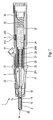
- figure 1 is a longitudinal sectional view of a device according to the invention.
- An injection device 1 according to the invention is intended to inject fuel into a combustion chamber of an internal combustion engine or into an air intake duct, not shown.
- the injection device comprises a cylindrical body made in two parts, a front portion 10 and a rear portion 11 coaxial, assembled together by screwing by a sleeve 12.
- the front portion 10 of the cylindrical body has a bore 15 coaxial with the cylindrical body and a seat 14 at one end of the front portion 10.
- a needle 2 is slidably mounted in the bore 15. It comprises a head 20 forming a valve with the seat 14.
- a channel 16 is formed in a space between the bore 15 and the needle 2 to channel fuel to the seat 14. The channel 16 is fed by a conduit 13 extending into the cylindrical body from an orifice connection 17.
- the rear portion 11 of the cylindrical body comprises a tubular sleeve 37 slidably mounted along the axis of the cylindrical body.
- the tubular bushing 37 is forced backwards by a bushing spring 4 bearing on a first shoulder 110 of the cylindrical body and a second shoulder 370 of the tubular bushing 37.
- the needle 2 has at its end opposite the head 20 a flange 21 on which an elastic washer 33 is supported.
- the spring washer 33 is also in abutment against a third shoulder 371 of the tubular sleeve 37 so as to transmit the tension of the socket spring 4 to the needle 2 by means of the spring washer 33, and thus to press the head 20 of the needle against the seat 14.
- the injection device 1 comprises, in the extension of the needle 2 towards the rear, an actuator 3 with an electro-active material and a flyweight 34.
- the actuator 3 comprises a bar 30 made of magnetostrictive material. surrounded by a coil 31 and a tube of ferromagnetic material 32.
- the bar 30 is for example made of Terfenol (registered trademark).
- the bar 30 is compressed by a prestressing device comprising a preload spring 35 bearing on a nipple 36 screwed into the sleeve 37 and tending to push the weight 34 against the bar 30.
- the tube of ferromagnetic material 32 is fitted on a cylinder guide 340 made at the end of the weight 34 on the side of the bar 30.
- the weight 34 is made of a material so that the impedance is greater than the impedance of the needle.
- the weight 34 is for example tungsten, while the needle 2 is made of steel or titanium.
- Z is of the order of 40,000,000
- for tungsten Z is of the order of 88,000,000
- titanium Z is of the order of 22 000 000.
- the more the impedance of the weight is greater than that of the needle the more the movement of the bar will be transmitted preferentially to the needle, which increases the efficiency of the system.
- a continuous signal and a periodic signal are applied to the actuator during the duration of the injection, substantially at the chosen excitation frequency. For this, it feeds, by means not shown, the coil 31 with a current comprising the continuous signal and the periodic signal.
- the bar 30 elongates on average as a function of the intensity of the continuous signal, and periodically at the excitation frequency. Given the different linear impedances, the bar 30 bears against the weight 34 and sets The induced movement of the head 20 of the needle is for example an average displacement of 20 to 30 microns and oscillations around this average position of the order of 10 to 20 microns.
- the actuator can be made with a bar made of piezoelectric material.
Landscapes
- Engineering & Computer Science (AREA)
- Chemical & Material Sciences (AREA)
- Combustion & Propulsion (AREA)
- Mechanical Engineering (AREA)
- General Engineering & Computer Science (AREA)
- Fuel-Injection Apparatus (AREA)
Abstract
Description
L'invention concerne dispositif d'injection de carburant, en particulier pour un moteur à combustion interne, et son procédé de commande.The invention relates to a fuel injection device, in particular for an internal combustion engine, and to its control method.
On connaît par le document
Avec un tel injecteur, le temps de réponse pour opérer la levée maximale du clapet est très court, typiquement inférieur à 50 µs. Il est donc possible de contrôler le degré d'ouverture du clapet pratiquement à chaque instant pendant la phase d'injection. On contrôle ainsi le débit instantané de carburant et la formation de gouttelettes de carburant.With such an injector, the response time to operate the maximum lift of the valve is very short, typically less than 50 microseconds. It is therefore possible to control the degree of opening of the valve substantially at each moment during the injection phase. This controls the instantaneous flow of fuel and the formation of fuel droplets.
Cependant, il est nécessaire que l'élément électro-actif soit à proximité immédiate de la tête. Or, du fait de la proximité de la chambre de combustion, l'élément électro-actif peut être porté à des températures susceptibles de dégrader son fonctionnement. De plus, son implantation au voisinage du nez de l'injecteur peut poser des problèmes d'encombrement.However, it is necessary that the element electro-active is in the immediate vicinity of the head. However, because of the proximity of the combustion chamber, the electro-active element can be raised to temperatures likely to degrade its operation. In addition, its location near the nose of the injector can cause congestion problems.
C'est donc un objectif de l'invention de proposer un dispositif d'injection de carburant dont la position de la tête de clapet puisse être contrôlée précisément avec un bon temps de réponse et dont l'élément électroactif soit dans des conditions de fonctionnement acceptables.It is therefore an object of the invention to provide a fuel injection device whose position of the valve head can be precisely controlled with a good response time and whose electroactive element is in acceptable operating conditions. .
Avec cet objectif en vue, l'invention a pour objet un dispositif d'injection de carburant comportant un corps cylindrique, une aiguille dont une extrémité comporte une tête formant clapet sur un siège porté par une extrémité du corps cylindrique, un actionneur à matériau électro-actif, l'actionneur comportant un barreau et étant apte à provoquer un déplacement de la tête pour ouvrir le clapet, une masselote prolongeant le barreau, un dispositif de précontrainte maintenant l'aiguille et la masselote en appui contre des extrémités opposées du barreau. L'aiguille s'étend coaxialement au corps cylindrique sous la forme d'une barre rigide, l'aiguille étant apte à entrer en résonance axiale lorsqu'elle est soumise par l'actionneur à des impulsions axiales à une fréquence d'excitation déterminée, superposant ainsi un mouvement vibratoire de la tête au mouvement d'ensemble de l'aiguille.With this object in view, the subject of the invention is a fuel injection device comprising a cylindrical body, a needle whose one end comprises a head forming a valve on a seat carried by one end of the cylindrical body, an actuator with electro-magnetic material. -Active, the actuator having a bar and being able to cause a displacement of the head to open the valve, a flyweight extending the bar, a prestressing device holding the needle and the flyweight bearing against opposite ends of the bar. The needle extends coaxially with the cylindrical body in the form of a rigid bar, the needle being able to enter into axial resonance when it is subjected by the actuator to axial pulses at a determined excitation frequency, thus superimposing a vibratory movement of the head to the overall motion of the needle.
La longueur de la barre permet de placer l'actionneur dans le corps du dispositif de manière distante de la tête, et donc d'être moins exposé à la chaleur de la chambre de combustion. La fréquence d'excitation est choisie proche d'une fréquence de mode propre de l'aiguille de manière à obtenir un phénomène de résonance par une successions de compression et d'extensions de l'aiguille dans le sens axial. Par ailleurs, le fait de pouvoir mettre la barre en résonance dans le sens axial du dispositif permet d'obtenir un mode de déplacement de la tête dans la direction axiale à la fréquence d'excitation choisie. La fréquence choisie est par exemple telle que la période d'oscillation est très inférieure à la durée d'une phase d'injection. Les oscillations de la tête permettent de moduler le débit de carburant et ainsi de contrôler la formation de très fines gouttelettes de carburant. Ces oscillations (provenant du mouvement vibratoire) se superposent au mouvement d'ensemble de l'aiguille. Les deux actions se déroulent simultanément. Lorsque le barreau se déforme sous l'effet d'un signal, il prend appui à une extrémité contre l'aiguille, et à l'autre extrémité contre la masselotte. La réaction de la masselotte sur le barreau permet de transmettre une partie essentielle du mouvement du barreau à l'aiguille.The length of the bar allows to place the actuator in the body of the device away from the head, and therefore to be less exposed to the heat of the combustion chamber. The excitation frequency is chosen close to a self-mode frequency of the needle so as to obtain a resonance phenomenon by successions of compression and extensions of the needle in the axial direction. Furthermore, the fact of being able to resonate the bar in the axial direction of the device makes it possible to obtain a mode of displacement of the head in the axial direction at the chosen excitation frequency. The chosen frequency is for example such that the oscillation period is much shorter than the duration of an injection phase. Oscillations of the head can modulate the fuel flow and thus control the formation of very fine fuel droplets. These oscillations (coming from the vibratory movement) are superimposed on the overall movement of the needle. Both actions take place simultaneously. When the bar is deformed under the effect of a signal, it is supported at one end against the needle, and at the other end against the weight. The reaction of the weight on the bar makes it possible to transmit an essential part of the movement of the bar to the needle.
A titre d'exemple, la fréquence d'excitation est située dans une plage s'étendant de 10 à 30 kHz. On peut ainsi obtenir la formation de très fines gouttelettes pendant la phase d'injection.By way of example, the excitation frequency is in a range extending from 10 to 30 kHz. It is thus possible to obtain the formation of very fine droplets during the injection phase.
Dans un premier mode de réalisation, le barreau est en matériau magnétostrictif et est entouré par une bobine apte à créer un champ magnétique dans le barreau. Lorsqu'un tel matériau est soumis à un champ magnétique, il subit un allongement qui est transmis à l'aiguille. L'aiguille se déplace alors axialement dans le sens d'une ouverture du clapet. Selon la fréquence du champ magnétique, l'aiguille se déplace dans son ensemble, pour une basse fréquence, ou s'allonge et se rétracte en résonance si le champ magnétique est à une fréquence d'excitation apte à mettre l'aiguille en résonance, c'est-à-dire proche d'une fréquence de mode propre de l'aiguille.In a first embodiment, the bar is made of magnetostrictive material and is surrounded by a coil capable of creating a magnetic field in the bar. When such material is subjected to a magnetic field, it undergoes an elongation which is transmitted to the needle. The needle then moves axially in the direction of an opening of the valve. According to the frequency of the magnetic field, the needle moves as a whole, for a low frequency, or lengthens and retracts into resonance if the magnetic field is at an excitation frequency capable of resonating the needle, that is, close to a self-mode frequency of the needle.
De préférence, un tube en matériau ferromagnétique entoure la bobine. Ainsi, le champ magnétique créé dans le barreau est bouclé sur lui-même grâce au tube, ce qui augmente l'efficacité de la bobine.Preferably, a tube of ferromagnetic material surrounds the coil. Thus, the magnetic field created in the bar is looped on itself thanks to the tube, which increases the effectiveness of the coil.
Dans un deuxième mode de réalisation, le barreau est en matériau piézo-électrique.In a second embodiment, the bar is made of piezoelectric material.
De préférence, l'impédance de la masselotte est supérieure à l'impédance de l'aiguille. L'impédance est définie par le produit de la masse volumique et de la célérité acoustique dans le matériau constitutif de la masselotte. L'impédance caractérise le comportement dynamique du matériau. Comme l'impédance de la masselotte est plus importante, le déplacement provoqué se répercute essentiellement sur l'aiguille, sous la forme d'une déformation ou d'un déplacement. Ainsi, même si la masselotte n'est pas fixée au corps du dispositif, l'ensemble formé par l'aiguille, le barreau et la masselotte se comporte, aux fréquences utilisées, comme si la masselotte était fixe.Preferably, the impedance of the flyweight is greater than the impedance of the needle. Impedance is defined by the product of density and acoustic celerity in the constituent material of the flyweight. Impedance characterizes the dynamic behavior of the material. As the impedance of the flyweight is greater, the displacement caused is mainly reflected on the needle, in the form of a deformation or displacement. Thus, even if the weight is not fixed to the body of the device, the assembly formed by the needle, the bar and the flyweight behaves, at the frequencies used, as if the flyweight was fixed.
De manière particulière, le dispositif de précontrainte comporte une douille tubulaire contenant la masselotte et l'actionneur, un ressort de précontrainte prenant appui sur la douille et tendant à pousser la masselotte contre le barreau, et une rondelle élastique, l'aiguille comportant une collerette, la rondelle élastique prenant appui sur la collerette pour comprimer l'aiguille contre le barreau. La précontrainte en compression du barreau permet d'augmenter l'amplitude de fonctionnement du barreau. Dans cette configuration, l'application de la précontrainte permet également d'appliquer la masselotte et l'aiguille contre le barreau. De plus, le mouvement de l'extrémité du barreau en contact avec l'aiguille est autorisé par la déformation élastique de la rondelle.In particular, the prestressing device comprises a tubular sleeve containing the flyweight and the actuator, a biasing spring bearing on the sleeve and tending to push the counterweight against the bar, and an elastic washer, the needle having a collar , the spring washer bearing on the flange to compress the needle against the bar. Preloading in compression of the bar makes it possible to increase the amplitude of operation of the bar. In this configuration, the application of the prestressing also makes it possible to apply the weight and the needle against the bar. In addition, the movement of the end of the bar in contact with the needle is allowed by the elastic deformation of the washer.
Selon un perfectionnement, l'ensemble comprenant l'aiguille, le dispositif de précontrainte et l'actionneur est monté coulissant dans le corps cylindrique, des moyens d'appui agissant sur ledit ensemble et tendant à mettre la tête en appui contre le siège. Ce montage permet de compenser les dilatations différentielles dans le dispositif dues aux différences de température des composants et des caractéristiques de dilatation de chaque composant. Les phases d'injection pendant lesquelles la tête de l'aiguille n'est plus en appui contre le siège sont suffisamment courtes pour que l'ensemble comprenant l'aiguille, le dispositif de précontrainte et l'actionneur n'ait pas le temps de se déplacer et de venir refermer le clapet.According to an improvement, the assembly comprising the needle, the prestressing device and the actuator is slidably mounted in the cylindrical body, bearing means acting on said assembly and tending to put the head bearing against the seat. This arrangement makes it possible to compensate for the differential expansions in the device due to the differences in the temperature of the components and the expansion characteristics of each component. The injection phases during which the head of the needle is no longer supported against the seat are short enough that the assembly comprising the needle, the prestressing device and the actuator does not have the time to move and come close the flap.
L'invention a aussi pour objet un procédé de commande d'un dispositif d'injection tel que décrit précédemment, selon lequel on commande une phase d'injection en appliquant à l'actionneur un signal continu pendant la durée de l'injection et un signal périodique à une fréquence d'excitation apte à provoquer la mise en résonance de l'aiguille. Le signal continu a pour effet de commander un déplacement de l'aiguille dans son ensemble, tandis que le signal périodique a pour effet de mettre l'aiguille en résonance. On peut moduler l'amplitude du déplacement de l'aiguille ainsi que l'amplitude de ses oscillations. L'amplitude de ces deux signaux peut être modulée lors d'une phase d'injection.The subject of the invention is also a method of control of an injection device as described above, according to which an injection phase is controlled by applying to the actuator a continuous signal during the duration of the injection and a periodic signal at an excitation frequency suitable for cause resonance of the needle. The continuous signal has the effect of controlling a movement of the needle as a whole, while the periodic signal has the effect of putting the needle into resonance. One can modulate the amplitude of the displacement of the needle as well as the amplitude of its oscillations. The amplitude of these two signals can be modulated during an injection phase.
Selon un perfectionnement, on superpose un signal d'amortissement obtenu par la transformée inverse du mouvement oscillatoire simulé de la tête en cas de coupure du signal de commande. Si on coupe brutalement le signal de commande, la tête de l'aiguillé revient vers la position contre le siège avec une vitesse importante à cause de la superposition des deux signaux, ce qui génère un choc. En simulant le mouvement de la tête en l'absence du siège, on obtient un mouvement oscillatoire autour de la position de repos de la tête. En appliquant une transformée inverse à ce mouvement oscillatoire, on obtient un signal d'amortissement qui, lorsqu'il est appliqué au signal de commande, permet d'obtenir un mouvement amorti de la tête. Celle-ci accoste alors délicatement le siège à la fin de la période d'injection.According to an improvement, a damping signal obtained by the inverse transform of the simulated oscillatory movement of the head is superimposed in the event of the control signal being cut off. If the control signal is abruptly cut off, the head of the refit returns to the position against the seat with a high speed because of the superposition of the two signals, which generates a shock. By simulating the movement of the head in the absence of the seat, an oscillatory movement is obtained around the rest position of the head. By applying an inverse transform to this oscillatory motion, a damping signal is obtained which, when applied to the control signal, provides a cushioned movement of the head. It then gently docking the seat at the end of the injection period.
L'invention sera mieux comprise et d'autres particularités et avantages apparaîtront à la lecture de la description qui va suivre, la description faisant référence à la
Un dispositif d'injection 1 conforme à l'invention, montré sur la
Le dispositif d'injection comporte un corps cylindrique réalisé en deux parties, une partie avant 10 et une partie arrière 11 coaxiales, assemblées entre elles par vissage par un manchon 12.The injection device comprises a cylindrical body made in two parts, a
La partie avant 10 du corps cylindrique comporte un alésage 15 coaxial avec le corps cylindrique et un siège 14 à une extrémité de la partie avant 10. Une aiguille 2 est montée coulissante dans l'alésage 15. Elle comporte une tête 20 formant clapet avec le siège 14. Un canal 16 est ménagé dans un espace entre l'alésage 15 et l'aiguille 2 pour canaliser du carburant jusqu'au siège 14. Le canal 16 est alimenté par un conduit 13 s'étendant dans le corps cylindrique depuis un orifice de connexion 17.The
La partie arrière 11 du corps cylindrique comporte une douille tubulaire 37 montée coulissante selon l'axe du corps cylindrique. La douille tubulaire 37 est contrainte vers l'arrière par un ressort de douille 4 prenant appui sur un premier épaulement 110 du corps cylindrique et un deuxième épaulement 370 de la douille tubulaire 37.The
L'aiguille 2 comporte à son extrémité opposée à la tête 20 une collerette 21 sur laquelle une rondelle élastique 33 est en appui. La rondelle élastique 33 est également en appui contre un troisième épaulement 371 de la douille tubulaire 37 de manière à transmettre la tension du ressort de douille 4 à l'aiguille 2 par l'intermédiaire de la rondelle élastique 33, et ainsi à plaquer la tête 20 de l'aiguille contre le siège 14.The
Le dispositif d'injection 1 comporte dans le prolongement de l'aiguille 2 vers l'arrière un actionneur 3 à matériau électro-actif et une masselotte 34. Dans le mode de réalisation décrit, l'actionneur 3 comporte un barreau 30 en matériau magnétostrictif entouré d'une bobine 31 et d'un tube en matériau ferromagnétique 32. Le barreau 30 est par exemple réalisé en Terfenol (marque déposée). Le barreau 30 est comprimé par un dispositif de précontrainte comportant un ressort de précontrainte 35 prenant appui sur un mamelon 36 vissé dans la douille 37 et tendant à pousser la masselotte 34 contre le barreau 30. Le tube en matériau ferromagnétique 32 est emmanché sur un cylindre de guidage 340 réalisé à l'extrémité de la masselotte 34 du côté du barreau 30.The injection device 1 comprises, in the extension of the
La longueur de l'aiguille 2 est déterminée, en lien avec son matériau constitutif pour que l'aiguille entre en résonance lorsqu'elle est soumise à des oscillations axiales à une fréquence d'excitation située dans une plage s'étendant de 10 à 30 kHz. La résonance est obtenue lorsque l'aiguille est soumise à des sollicitations à une fréquence proche d'une fréquence propre oscillatoire de l'aiguille. Si l'aiguille a une longueur 1, on a différentes fréquences propres fn telles que fn=(2n+1)C/(4x1) avec n entier positif ou nul, et C la célérité dans le matériau de l'aiguille.The length of the
La masselotte 34 est réalisée dans un matériau pour que l'impédance soit supérieure à l'impédance de l'aiguille. La masselotte 34 est par exemple en tungstène, alors que l'aiguille 2 est en acier ou en titane. L'impédance est définie par la formule Z=ρC, avec ρ : masse volumique en kg•m-3, et C : célérité acoustique dans le matériau en m·s-1. On peut également exprimer l'impédance par ![]()
![]()
Lorsqu'on commande une phase d'injection, on applique à l'actionneur pendant la durée de l'injection un signal continu et un signal périodique sensiblement à la fréquence d'excitation choisie. Pour cela, on alimente, par des moyens non représentés, la bobine 31 avec un courant comportant le signal continu et le signal périodique. En conséquence, le barreau 30 s'allonge en moyenne en fonction de l'intensité du signal continu, et périodiquement à la fréquence d'excitation. Compte tenu des différentes impédances linéaires, le barreau 30 prend appui contre la masselotte 34 et met en mouvement et en oscillation l'aiguille 2. Le mouvement induit de la tête 20 de l'aiguille est par exemple un déplacement moyen de 20 à 30 µm et des oscillations autour de cette position moyenne de l'ordre de 10 à 20 µm.When controlling an injection phase, a continuous signal and a periodic signal are applied to the actuator during the duration of the injection, substantially at the chosen excitation frequency. For this, it feeds, by means not shown, the
L'invention n'est pas limitée au mode de réalisation décrit uniquement à titre d'exemple. L'actionneur peut être réalisé avec un barreau en matériau piézo-électrique.The invention is not limited to the embodiment described solely by way of example. The actuator can be made with a bar made of piezoelectric material.
Claims (10)
- Fuel injection device comprising a cylindrical body (11, 12), a needle (2) one end of which has a head (20) acting as a valve on a seat (14) borne by one end of the cylindrical body, an electroactive material actuator (3), there being a control capable of activating the actuator (3) at an excitation frequency, the actuator comprising a rod (30) and being able to cause the head (20) to move in order to open the valve, a weight (34) extending the rod (30), a preloading device (35, 36, 37, 33) keeping the needle (2) and the weight (34) pressed against opposite ends of the rod (30), characterized in that the needle (2) runs coaxially with respect to the cylindrical body (11, 12) in the form of a bar, the needle (2) being able to go into axial resonance when subjected by the actuator (3) to axial impulses at a given excitation frequency, thus superimposing vibrational movement of the head (20) on the overall movement of the needle (2).
- Injection device according to Claim 1, in which the excitation frequency lies in a range extending from 10 to 30 kHz.
- Injection device according to Claim 1, in which the rod (30) is made of magnetostrictive material and is surrounded by a coil (31) able to create a magnetic field in the rod (30).
- Injection device according to Claim 3, in which a tube (32) made of ferromagnetic material surrounds the coil (31).
- Injection device according to Claim 1, in which the rod (30) is made of piezoelectric material.
- Injection device according to Claim 5, in which the impedance of the weight (34) is greater than the impedance of the needle (2).
- Injection device according to Claim 6, in which the preloading device comprises a tubular sleeve tube (37) containing the weight (34) and the actuator (3), a preloading spring (35) pressing against the sleeve tube (37) and tending to push the weight (34) against the rod (30), and an elastic washer (33), the needle (2) having a flange (21), the elastic washer (33) bearing against the flange (21) in order to compress the needle (2) against the rod (30).
- Injection device according to Claim 7, in which the assembly comprising the needle (2), the preloading device (33, 37, 35) and the actuator (3) is mounted such that it can slide in the cylindrical body (11), there being pressing means (4) acting on said assembly and tending to press the head (20) against the seat (14).
- Method of controlling an injection device according to one of Claims 1 to 8, characterized in that an injection phase is performed by applying to the actuator (3) a continuous signal during the injection period and a periodic signal at an excitation frequency capable of causing the needle (2) to go into resonance.
- Control method according to Claim 9, in which a damping signal obtained via the inverse transform of the simulated oscillatory movement of the head (14) is superposed if the control signal is cut off.
Applications Claiming Priority (2)
| Application Number | Priority Date | Filing Date | Title |
|---|---|---|---|
| FR0508182A FR2889257B1 (en) | 2005-08-01 | 2005-08-01 | FUEL INJECTION DEVICE AND METHOD FOR CONTROLLING SUCH A DEVICE |
| PCT/FR2006/050740 WO2007015022A1 (en) | 2005-08-01 | 2006-07-20 | Fuel injecting device and method for controlling said device |
Publications (2)
| Publication Number | Publication Date |
|---|---|
| EP1913253A1 EP1913253A1 (en) | 2008-04-23 |
| EP1913253B1 true EP1913253B1 (en) | 2009-03-11 |
Family
ID=36021719
Family Applications (1)
| Application Number | Title | Priority Date | Filing Date |
|---|---|---|---|
| EP06794493A Active EP1913253B1 (en) | 2005-08-01 | 2006-07-20 | Fuel injecting device and method for controlling said device |
Country Status (10)
| Country | Link |
|---|---|
| US (1) | US7784708B2 (en) |
| EP (1) | EP1913253B1 (en) |
| KR (1) | KR101129016B1 (en) |
| CN (1) | CN101233313B (en) |
| AT (1) | ATE425354T1 (en) |
| DE (1) | DE602006005682D1 (en) |
| ES (1) | ES2320041T3 (en) |
| FR (1) | FR2889257B1 (en) |
| RU (1) | RU2439362C2 (en) |
| WO (1) | WO2007015022A1 (en) |
Families Citing this family (9)
| Publication number | Priority date | Publication date | Assignee | Title |
|---|---|---|---|---|
| FR2918123A1 (en) * | 2007-06-27 | 2009-01-02 | Renault Sas | FLUID INJECTION DEVICE. |
| FR2922964B1 (en) | 2007-10-31 | 2009-11-20 | Renault Sas | RESONANT NEEDLE FLUID INJECTION DEVICE FOR INTERNAL COMBUSTION ENGINE |
| FR2924176A3 (en) | 2007-11-27 | 2009-05-29 | Renault Sas | Fluid e.g. pressurized liquid fuel, injecting device e.g. injector, for internal combustion engine, has actuator for placing resonant needle in axial oscillation, and bellow forming sealing between mobile element and end of nozzle tip |
| DE102008054591A1 (en) * | 2008-12-12 | 2010-06-17 | Robert Bosch Gmbh | Decoupling element for a fuel injection device |
| FR2941746A1 (en) | 2009-02-02 | 2010-08-06 | Renault Sas | DEVICE FOR INJECTING LIQUID, IN PARTICULAR FUEL, WITH ELECTROACTIVE ACTUATOR. |
| FR2949247B1 (en) | 2009-08-24 | 2011-09-16 | Renault Sa | SYSTEM FOR MOUNTING A RESONANT NEEDLE INJECTION DEVICE. |
| FR2978301B1 (en) | 2011-07-18 | 2013-08-02 | Renault Sa | METHOD FOR ASSEMBLING AN ULTRASONIC TRANSDUCER AND TRANSDUCER OBTAINED BY THE METHOD |
| RU2540347C2 (en) * | 2013-01-24 | 2015-02-10 | Федеральное государственнное бюджетное образовательное учреждение высшего профессионального образования "Ярославский государственный технический университет" | Ice electrically-controlled fuel injector |
| US10119507B1 (en) * | 2017-07-17 | 2018-11-06 | GM Global Technology Operations LLC | Rotating fuel injector assembly |
Family Cites Families (9)
| Publication number | Priority date | Publication date | Assignee | Title |
|---|---|---|---|---|
| DE3314899A1 (en) * | 1983-04-25 | 1984-10-25 | Mesenich, Gerhard, Dipl.-Ing., 4630 Bochum | SPRING ARRANGEMENT WITH ADDITIONAL DIMENSIONS FOR IMPROVING THE DYNAMIC BEHAVIOR OF ELECTROMAGNET SYSTEMS |
| DE19546033A1 (en) * | 1995-12-09 | 1997-06-12 | Bosch Gmbh Robert | Fuel injection valve for internal combustion engines |
| US6318646B1 (en) * | 1999-03-26 | 2001-11-20 | MAGNETI MARELLI S.p.A. | Fuel injector |
| JP2000297720A (en) * | 1999-04-13 | 2000-10-24 | Hitachi Ltd | Fuel injection system |
| JP3816801B2 (en) * | 2000-01-26 | 2006-08-30 | 株式会社日立製作所 | Electromagnetic fuel injection valve |
| US6543700B2 (en) * | 2000-12-11 | 2003-04-08 | Kimberly-Clark Worldwide, Inc. | Ultrasonic unitized fuel injector with ceramic valve body |
| DE10148603B4 (en) * | 2001-10-02 | 2004-02-19 | Siemens Ag | Actuator unit with at least two actuator elements |
| DE10232193A1 (en) * | 2002-07-16 | 2004-02-05 | Robert Bosch Gmbh | Fuel injector |
| FR2854664B1 (en) | 2003-05-09 | 2006-06-30 | Renault Sa | FLUID INJECTION DEVICE |
-
2005
- 2005-08-01 FR FR0508182A patent/FR2889257B1/en not_active Expired - Fee Related
-
2006
- 2006-07-20 RU RU2008107952/06A patent/RU2439362C2/en not_active Application Discontinuation
- 2006-07-20 KR KR1020087004631A patent/KR101129016B1/en active IP Right Grant
- 2006-07-20 US US11/997,648 patent/US7784708B2/en not_active Expired - Fee Related
- 2006-07-20 EP EP06794493A patent/EP1913253B1/en active Active
- 2006-07-20 CN CN2006800283803A patent/CN101233313B/en active Active
- 2006-07-20 AT AT06794493T patent/ATE425354T1/en not_active IP Right Cessation
- 2006-07-20 DE DE602006005682T patent/DE602006005682D1/en active Active
- 2006-07-20 WO PCT/FR2006/050740 patent/WO2007015022A1/en active Application Filing
- 2006-07-20 ES ES06794493T patent/ES2320041T3/en active Active
Also Published As
| Publication number | Publication date |
|---|---|
| CN101233313A (en) | 2008-07-30 |
| ES2320041T3 (en) | 2009-05-18 |
| EP1913253A1 (en) | 2008-04-23 |
| US20080315019A1 (en) | 2008-12-25 |
| WO2007015022A1 (en) | 2007-02-08 |
| FR2889257B1 (en) | 2007-11-02 |
| RU2008107952A (en) | 2009-09-10 |
| FR2889257A1 (en) | 2007-02-02 |
| CN101233313B (en) | 2011-02-16 |
| US7784708B2 (en) | 2010-08-31 |
| DE602006005682D1 (en) | 2009-04-23 |
| KR101129016B1 (en) | 2012-03-28 |
| KR20080043790A (en) | 2008-05-19 |
| ATE425354T1 (en) | 2009-03-15 |
| RU2439362C2 (en) | 2012-01-10 |
Similar Documents
| Publication | Publication Date | Title |
|---|---|---|
| EP1913253B1 (en) | Fuel injecting device and method for controlling said device | |
| FR2738294A1 (en) | INJECTOR FOR INTERNAL COMBUSTION ENGINE | |
| EP1910665B1 (en) | Fuel injection device for internal combustion engine | |
| FR2740177A1 (en) | PIEZOELECTRIC CONTROL INJECTOR FOR FUEL INJECTION SYSTEMS OF INTERNAL COMBUSTION ENGINES | |
| EP1963665B1 (en) | Fuel injector for an internal combustion engine | |
| EP1248904B1 (en) | Fuel injecting device for internal combustion engine | |
| FR2488655A2 (en) | FUEL INJECTOR EQUIPPED WITH A ULTRA-SOUND VIBRATION RETENTION CHECK, IN PARTICULAR FOR A DIESEL ENGINE | |
| FR2463347A1 (en) | ELECTRICALLY CONTROLLED VALVE | |
| FR2786269A1 (en) | DEVICE FOR THE INJECTION OF A FLUID COMPRISING A VARIATION IN THE PRESSURE OF THE FLUID INJECTED | |
| FR2815085A1 (en) | IMPROVED FUEL INJECTOR STRUCTURE FOR AVOIDING INJECTION OF AN EXCESSIVE FUEL QUANTITY | |
| FR2933748A1 (en) | FUEL INJECTOR DEVICE | |
| EP1172552B1 (en) | Fuel injection device for internal combustion engine | |
| FR2866395A1 (en) | FUEL INJECTOR FOR INTERNAL COMBUSTION ENGINE | |
| EP2324230B1 (en) | Fluid injection device | |
| WO2009056774A1 (en) | Fuel injection device with resonant needle for internal combustion engine | |
| FR2941745A3 (en) | Liquid i.e. fuel, injecting device, has electroactive material actuator triggering movement of head of needle, needle piston carried by end of needle, and hydraulic chamber connected to duct to maintain chamber supplied with liquid | |
| FR2857418A1 (en) | Pre-stress application device for fuel injection device, has joint placed between mass and rod to form high pressure zone in vicinity of end of rod cooperating with valve seat and low pressure zone encompassing major part of mass | |
| EP3489505B1 (en) | Injector valve needle | |
| FR2918122A1 (en) | FLUID INJECTION DEVICE. | |
| WO2010086553A1 (en) | Device for injecting a liquid, in particular a fuel, with an electroactive actuator | |
| EP1342913B1 (en) | Fuel injector | |
| WO2010031935A1 (en) | Fluid injection device | |
| FR2924176A3 (en) | Fluid e.g. pressurized liquid fuel, injecting device e.g. injector, for internal combustion engine, has actuator for placing resonant needle in axial oscillation, and bellow forming sealing between mobile element and end of nozzle tip | |
| FR2927669A1 (en) | Fuel injecting device i.e. fuel injector, for e.g. diesel engine, of automobile, has actuating units displacing movable element between closing and disengaged positions of orifice and provided with dampening units | |
| FR2861813A1 (en) | Internal combustion engine, has injector fixed to support and injecting fuel, and radial lateral pipe and radial lateral orifice introducing oil into chambers to displace injector with respect to cylinder in two opposite directions |
Legal Events
| Date | Code | Title | Description |
|---|---|---|---|
| PUAI | Public reference made under article 153(3) epc to a published international application that has entered the european phase |
Free format text: ORIGINAL CODE: 0009012 |
|
| 17P | Request for examination filed |
Effective date: 20080303 |
|
| AK | Designated contracting states |
Kind code of ref document: A1 Designated state(s): AT BE BG CH CY CZ DE DK EE ES FI FR GB GR HU IE IS IT LI LT LU LV MC NL PL PT RO SE SI SK TR |
|
| GRAP | Despatch of communication of intention to grant a patent |
Free format text: ORIGINAL CODE: EPIDOSNIGR1 |
|
| GRAS | Grant fee paid |
Free format text: ORIGINAL CODE: EPIDOSNIGR3 |
|
| GRAA | (expected) grant |
Free format text: ORIGINAL CODE: 0009210 |
|
| AK | Designated contracting states |
Kind code of ref document: B1 Designated state(s): AT BE BG CH CY CZ DE DK EE ES FI FR GB GR HU IE IS IT LI LT LU LV MC NL PL PT RO SE SI SK TR |
|
| REG | Reference to a national code |
Ref country code: GB Ref legal event code: FG4D Free format text: NOT ENGLISH |
|
| REG | Reference to a national code |
Ref country code: CH Ref legal event code: EP |
|
| REG | Reference to a national code |
Ref country code: IE Ref legal event code: FG4D Free format text: LANGUAGE OF EP DOCUMENT: FRENCH |
|
| REF | Corresponds to: |
Ref document number: 602006005682 Country of ref document: DE Date of ref document: 20090423 Kind code of ref document: P |
|
| REG | Reference to a national code |
Ref country code: ES Ref legal event code: FG2A Ref document number: 2320041 Country of ref document: ES Kind code of ref document: T3 |
|
| PG25 | Lapsed in a contracting state [announced via postgrant information from national office to epo] |
Ref country code: SI Free format text: LAPSE BECAUSE OF FAILURE TO SUBMIT A TRANSLATION OF THE DESCRIPTION OR TO PAY THE FEE WITHIN THE PRESCRIBED TIME-LIMIT Effective date: 20090311 Ref country code: NL Free format text: LAPSE BECAUSE OF FAILURE TO SUBMIT A TRANSLATION OF THE DESCRIPTION OR TO PAY THE FEE WITHIN THE PRESCRIBED TIME-LIMIT Effective date: 20090311 Ref country code: LT Free format text: LAPSE BECAUSE OF FAILURE TO SUBMIT A TRANSLATION OF THE DESCRIPTION OR TO PAY THE FEE WITHIN THE PRESCRIBED TIME-LIMIT Effective date: 20090311 Ref country code: FI Free format text: LAPSE BECAUSE OF FAILURE TO SUBMIT A TRANSLATION OF THE DESCRIPTION OR TO PAY THE FEE WITHIN THE PRESCRIBED TIME-LIMIT Effective date: 20090311 |
|
| NLV1 | Nl: lapsed or annulled due to failure to fulfill the requirements of art. 29p and 29m of the patents act | ||
| PG25 | Lapsed in a contracting state [announced via postgrant information from national office to epo] |
Ref country code: LV Free format text: LAPSE BECAUSE OF FAILURE TO SUBMIT A TRANSLATION OF THE DESCRIPTION OR TO PAY THE FEE WITHIN THE PRESCRIBED TIME-LIMIT Effective date: 20090311 Ref country code: SE Free format text: LAPSE BECAUSE OF FAILURE TO SUBMIT A TRANSLATION OF THE DESCRIPTION OR TO PAY THE FEE WITHIN THE PRESCRIBED TIME-LIMIT Effective date: 20090611 Ref country code: PL Free format text: LAPSE BECAUSE OF FAILURE TO SUBMIT A TRANSLATION OF THE DESCRIPTION OR TO PAY THE FEE WITHIN THE PRESCRIBED TIME-LIMIT Effective date: 20090311 Ref country code: AT Free format text: LAPSE BECAUSE OF FAILURE TO SUBMIT A TRANSLATION OF THE DESCRIPTION OR TO PAY THE FEE WITHIN THE PRESCRIBED TIME-LIMIT Effective date: 20090311 |
|
| REG | Reference to a national code |
Ref country code: IE Ref legal event code: FD4D |
|
| PG25 | Lapsed in a contracting state [announced via postgrant information from national office to epo] |
Ref country code: PT Free format text: LAPSE BECAUSE OF FAILURE TO SUBMIT A TRANSLATION OF THE DESCRIPTION OR TO PAY THE FEE WITHIN THE PRESCRIBED TIME-LIMIT Effective date: 20090824 Ref country code: CZ Free format text: LAPSE BECAUSE OF FAILURE TO SUBMIT A TRANSLATION OF THE DESCRIPTION OR TO PAY THE FEE WITHIN THE PRESCRIBED TIME-LIMIT Effective date: 20090311 Ref country code: IE Free format text: LAPSE BECAUSE OF FAILURE TO SUBMIT A TRANSLATION OF THE DESCRIPTION OR TO PAY THE FEE WITHIN THE PRESCRIBED TIME-LIMIT Effective date: 20090311 Ref country code: EE Free format text: LAPSE BECAUSE OF FAILURE TO SUBMIT A TRANSLATION OF THE DESCRIPTION OR TO PAY THE FEE WITHIN THE PRESCRIBED TIME-LIMIT Effective date: 20090311 |
|
| PG25 | Lapsed in a contracting state [announced via postgrant information from national office to epo] |
Ref country code: IS Free format text: LAPSE BECAUSE OF FAILURE TO SUBMIT A TRANSLATION OF THE DESCRIPTION OR TO PAY THE FEE WITHIN THE PRESCRIBED TIME-LIMIT Effective date: 20090711 Ref country code: SK Free format text: LAPSE BECAUSE OF FAILURE TO SUBMIT A TRANSLATION OF THE DESCRIPTION OR TO PAY THE FEE WITHIN THE PRESCRIBED TIME-LIMIT Effective date: 20090311 Ref country code: RO Free format text: LAPSE BECAUSE OF FAILURE TO SUBMIT A TRANSLATION OF THE DESCRIPTION OR TO PAY THE FEE WITHIN THE PRESCRIBED TIME-LIMIT Effective date: 20090311 |
|
| PLBE | No opposition filed within time limit |
Free format text: ORIGINAL CODE: 0009261 |
|
| STAA | Information on the status of an ep patent application or granted ep patent |
Free format text: STATUS: NO OPPOSITION FILED WITHIN TIME LIMIT |
|
| PG25 | Lapsed in a contracting state [announced via postgrant information from national office to epo] |
Ref country code: BG Free format text: LAPSE BECAUSE OF FAILURE TO SUBMIT A TRANSLATION OF THE DESCRIPTION OR TO PAY THE FEE WITHIN THE PRESCRIBED TIME-LIMIT Effective date: 20090611 Ref country code: DK Free format text: LAPSE BECAUSE OF FAILURE TO SUBMIT A TRANSLATION OF THE DESCRIPTION OR TO PAY THE FEE WITHIN THE PRESCRIBED TIME-LIMIT Effective date: 20090311 |
|
| 26N | No opposition filed |
Effective date: 20091214 |
|
| PG25 | Lapsed in a contracting state [announced via postgrant information from national office to epo] |
Ref country code: MC Free format text: LAPSE BECAUSE OF NON-PAYMENT OF DUE FEES Effective date: 20090731 |
|
| PG25 | Lapsed in a contracting state [announced via postgrant information from national office to epo] |
Ref country code: GR Free format text: LAPSE BECAUSE OF FAILURE TO SUBMIT A TRANSLATION OF THE DESCRIPTION OR TO PAY THE FEE WITHIN THE PRESCRIBED TIME-LIMIT Effective date: 20090612 |
|
| REG | Reference to a national code |
Ref country code: CH Ref legal event code: PL |
|
| PG25 | Lapsed in a contracting state [announced via postgrant information from national office to epo] |
Ref country code: LU Free format text: LAPSE BECAUSE OF NON-PAYMENT OF DUE FEES Effective date: 20090720 Ref country code: LI Free format text: LAPSE BECAUSE OF NON-PAYMENT OF DUE FEES Effective date: 20100731 Ref country code: CH Free format text: LAPSE BECAUSE OF NON-PAYMENT OF DUE FEES Effective date: 20100731 |
|
| PG25 | Lapsed in a contracting state [announced via postgrant information from national office to epo] |
Ref country code: HU Free format text: LAPSE BECAUSE OF FAILURE TO SUBMIT A TRANSLATION OF THE DESCRIPTION OR TO PAY THE FEE WITHIN THE PRESCRIBED TIME-LIMIT Effective date: 20090912 |
|
| PG25 | Lapsed in a contracting state [announced via postgrant information from national office to epo] |
Ref country code: TR Free format text: LAPSE BECAUSE OF FAILURE TO SUBMIT A TRANSLATION OF THE DESCRIPTION OR TO PAY THE FEE WITHIN THE PRESCRIBED TIME-LIMIT Effective date: 20090311 |
|
| PG25 | Lapsed in a contracting state [announced via postgrant information from national office to epo] |
Ref country code: CY Free format text: LAPSE BECAUSE OF FAILURE TO SUBMIT A TRANSLATION OF THE DESCRIPTION OR TO PAY THE FEE WITHIN THE PRESCRIBED TIME-LIMIT Effective date: 20090311 |
|
| REG | Reference to a national code |
Ref country code: FR Ref legal event code: PLFP Year of fee payment: 10 |
|
| REG | Reference to a national code |
Ref country code: FR Ref legal event code: PLFP Year of fee payment: 11 |
|
| REG | Reference to a national code |
Ref country code: FR Ref legal event code: PLFP Year of fee payment: 12 |
|
| REG | Reference to a national code |
Ref country code: FR Ref legal event code: PLFP Year of fee payment: 13 |
|
| PGFP | Annual fee paid to national office [announced via postgrant information from national office to epo] |
Ref country code: IT Payment date: 20210727 Year of fee payment: 16 |
|
| PGFP | Annual fee paid to national office [announced via postgrant information from national office to epo] |
Ref country code: GB Payment date: 20210722 Year of fee payment: 16 Ref country code: DE Payment date: 20210721 Year of fee payment: 16 Ref country code: BE Payment date: 20210721 Year of fee payment: 16 |
|
| REG | Reference to a national code |
Ref country code: DE Ref legal event code: R119 Ref document number: 602006005682 Country of ref document: DE |
|
| GBPC | Gb: european patent ceased through non-payment of renewal fee |
Effective date: 20220720 |
|
| REG | Reference to a national code |
Ref country code: BE Ref legal event code: MM Effective date: 20220731 |
|
| PG25 | Lapsed in a contracting state [announced via postgrant information from national office to epo] |
Ref country code: GB Free format text: LAPSE BECAUSE OF NON-PAYMENT OF DUE FEES Effective date: 20220720 Ref country code: DE Free format text: LAPSE BECAUSE OF NON-PAYMENT OF DUE FEES Effective date: 20230201 Ref country code: BE Free format text: LAPSE BECAUSE OF NON-PAYMENT OF DUE FEES Effective date: 20220731 |
|
| P01 | Opt-out of the competence of the unified patent court (upc) registered |
Effective date: 20230608 |
|
| PG25 | Lapsed in a contracting state [announced via postgrant information from national office to epo] |
Ref country code: IT Free format text: LAPSE BECAUSE OF NON-PAYMENT OF DUE FEES Effective date: 20220720 |
|
| PGFP | Annual fee paid to national office [announced via postgrant information from national office to epo] |
Ref country code: ES Payment date: 20230926 Year of fee payment: 18 |
|
| PGFP | Annual fee paid to national office [announced via postgrant information from national office to epo] |
Ref country code: FR Payment date: 20230725 Year of fee payment: 18 |
|
| REG | Reference to a national code |
Ref country code: ES Ref legal event code: PC2A Owner name: NEW H POWERTRAIN HOLDING, S.L.U. Effective date: 20240805 |