EP1912840B1 - Electromechanical brake - Google Patents
Electromechanical brake Download PDFInfo
- Publication number
- EP1912840B1 EP1912840B1 EP06763514.4A EP06763514A EP1912840B1 EP 1912840 B1 EP1912840 B1 EP 1912840B1 EP 06763514 A EP06763514 A EP 06763514A EP 1912840 B1 EP1912840 B1 EP 1912840B1
- Authority
- EP
- European Patent Office
- Prior art keywords
- brake
- motor shaft
- cover
- electric motor
- rotation
- Prior art date
- Legal status (The legal status is an assumption and is not a legal conclusion. Google has not performed a legal analysis and makes no representation as to the accuracy of the status listed.)
- Active
Links
- 238000006243 chemical reaction Methods 0.000 claims description 11
- 230000007246 mechanism Effects 0.000 claims description 6
- 230000000903 blocking effect Effects 0.000 claims description 4
- 239000000470 constituent Substances 0.000 claims 1
- 230000005540 biological transmission Effects 0.000 description 3
- 238000010276 construction Methods 0.000 description 3
- 238000011161 development Methods 0.000 description 2
- 230000018109 developmental process Effects 0.000 description 2
- 238000004804 winding Methods 0.000 description 2
- 229910000831 Steel Inorganic materials 0.000 description 1
- 230000000295 complement effect Effects 0.000 description 1
- 230000006835 compression Effects 0.000 description 1
- 238000007906 compression Methods 0.000 description 1
- 230000001419 dependent effect Effects 0.000 description 1
- 230000004907 flux Effects 0.000 description 1
- 238000009434 installation Methods 0.000 description 1
- 239000004922 lacquer Substances 0.000 description 1
- 239000000463 material Substances 0.000 description 1
- 239000010959 steel Substances 0.000 description 1
Images

Classifications
-
- F—MECHANICAL ENGINEERING; LIGHTING; HEATING; WEAPONS; BLASTING
- F16—ENGINEERING ELEMENTS AND UNITS; GENERAL MEASURES FOR PRODUCING AND MAINTAINING EFFECTIVE FUNCTIONING OF MACHINES OR INSTALLATIONS; THERMAL INSULATION IN GENERAL
- F16D—COUPLINGS FOR TRANSMITTING ROTATION; CLUTCHES; BRAKES
- F16D65/00—Parts or details
- F16D65/14—Actuating mechanisms for brakes; Means for initiating operation at a predetermined position
- F16D65/16—Actuating mechanisms for brakes; Means for initiating operation at a predetermined position arranged in or on the brake
- F16D65/18—Actuating mechanisms for brakes; Means for initiating operation at a predetermined position arranged in or on the brake adapted for drawing members together, e.g. for disc brakes
-
- B—PERFORMING OPERATIONS; TRANSPORTING
- B60—VEHICLES IN GENERAL
- B60T—VEHICLE BRAKE CONTROL SYSTEMS OR PARTS THEREOF; BRAKE CONTROL SYSTEMS OR PARTS THEREOF, IN GENERAL; ARRANGEMENT OF BRAKING ELEMENTS ON VEHICLES IN GENERAL; PORTABLE DEVICES FOR PREVENTING UNWANTED MOVEMENT OF VEHICLES; VEHICLE MODIFICATIONS TO FACILITATE COOLING OF BRAKES
- B60T13/00—Transmitting braking action from initiating means to ultimate brake actuator with power assistance or drive; Brake systems incorporating such transmitting means, e.g. air-pressure brake systems
- B60T13/74—Transmitting braking action from initiating means to ultimate brake actuator with power assistance or drive; Brake systems incorporating such transmitting means, e.g. air-pressure brake systems with electrical assistance or drive
- B60T13/741—Transmitting braking action from initiating means to ultimate brake actuator with power assistance or drive; Brake systems incorporating such transmitting means, e.g. air-pressure brake systems with electrical assistance or drive acting on an ultimate actuator
-
- F—MECHANICAL ENGINEERING; LIGHTING; HEATING; WEAPONS; BLASTING
- F16—ENGINEERING ELEMENTS AND UNITS; GENERAL MEASURES FOR PRODUCING AND MAINTAINING EFFECTIVE FUNCTIONING OF MACHINES OR INSTALLATIONS; THERMAL INSULATION IN GENERAL
- F16D—COUPLINGS FOR TRANSMITTING ROTATION; CLUTCHES; BRAKES
- F16D2121/00—Type of actuator operation force
- F16D2121/18—Electric or magnetic
- F16D2121/24—Electric or magnetic using motors
-
- F—MECHANICAL ENGINEERING; LIGHTING; HEATING; WEAPONS; BLASTING
- F16—ENGINEERING ELEMENTS AND UNITS; GENERAL MEASURES FOR PRODUCING AND MAINTAINING EFFECTIVE FUNCTIONING OF MACHINES OR INSTALLATIONS; THERMAL INSULATION IN GENERAL
- F16D—COUPLINGS FOR TRANSMITTING ROTATION; CLUTCHES; BRAKES
- F16D2123/00—Multiple operation forces
-
- F—MECHANICAL ENGINEERING; LIGHTING; HEATING; WEAPONS; BLASTING
- F16—ENGINEERING ELEMENTS AND UNITS; GENERAL MEASURES FOR PRODUCING AND MAINTAINING EFFECTIVE FUNCTIONING OF MACHINES OR INSTALLATIONS; THERMAL INSULATION IN GENERAL
- F16D—COUPLINGS FOR TRANSMITTING ROTATION; CLUTCHES; BRAKES
- F16D2125/00—Components of actuators
- F16D2125/18—Mechanical mechanisms
- F16D2125/20—Mechanical mechanisms converting rotation to linear movement or vice versa
- F16D2125/34—Mechanical mechanisms converting rotation to linear movement or vice versa acting in the direction of the axis of rotation
-
- F—MECHANICAL ENGINEERING; LIGHTING; HEATING; WEAPONS; BLASTING
- F16—ENGINEERING ELEMENTS AND UNITS; GENERAL MEASURES FOR PRODUCING AND MAINTAINING EFFECTIVE FUNCTIONING OF MACHINES OR INSTALLATIONS; THERMAL INSULATION IN GENERAL
- F16D—COUPLINGS FOR TRANSMITTING ROTATION; CLUTCHES; BRAKES
- F16D2127/00—Auxiliary mechanisms
- F16D2127/06—Locking mechanisms, e.g. acting on actuators, on release mechanisms or on force transmission mechanisms
-
- F—MECHANICAL ENGINEERING; LIGHTING; HEATING; WEAPONS; BLASTING
- F16—ENGINEERING ELEMENTS AND UNITS; GENERAL MEASURES FOR PRODUCING AND MAINTAINING EFFECTIVE FUNCTIONING OF MACHINES OR INSTALLATIONS; THERMAL INSULATION IN GENERAL
- F16D—COUPLINGS FOR TRANSMITTING ROTATION; CLUTCHES; BRAKES
- F16D2127/00—Auxiliary mechanisms
- F16D2127/08—Self-amplifying or de-amplifying mechanisms
- F16D2127/085—Self-amplifying or de-amplifying mechanisms having additional fluid pressure elements
-
- F—MECHANICAL ENGINEERING; LIGHTING; HEATING; WEAPONS; BLASTING
- F16—ENGINEERING ELEMENTS AND UNITS; GENERAL MEASURES FOR PRODUCING AND MAINTAINING EFFECTIVE FUNCTIONING OF MACHINES OR INSTALLATIONS; THERMAL INSULATION IN GENERAL
- F16D—COUPLINGS FOR TRANSMITTING ROTATION; CLUTCHES; BRAKES
- F16D2127/00—Auxiliary mechanisms
- F16D2127/08—Self-amplifying or de-amplifying mechanisms
- F16D2127/10—Self-amplifying or de-amplifying mechanisms having wedging elements
Definitions
- the invention relates to an electromechanical brake having the features of claim 1.
- Such brakes are known per se.
- the brakes For their operation, d. H. for pressing a friction brake lining against a rotatable brake body to be braked, the brakes have an electromechanical actuating device with an electric motor and a rotation / translation conversion gear, via which the friction brake lining can be pressed against the brake body with the electric motor.
- the electric motor and the rotation / translation conversion gear is often interposed a reduction gear).
- As a rotation / translation conversion gear helical gear are common, but there are other gear, such as rack and pinion or with the electric motor via a reduction gear cam which presses the friction brake pad against the brake body, to implement the rotary drive movement of the electric motor in a translational movement for pressing the friction brake lining against the brake body into consideration.
- An electromagnet in place of the electric motor is conceivable.
- the brake body is in the case of a disc brake a brake disc, in the case of a drum brake a brake drum.
- an example of such an electromechanical brake discloses the DE 102 55 192 A1 ,
- a parking brake parking brake
- the known brake on a switchable freewheel which locks in a switched-on position, a motor shaft of the electric motor against rotation in a release direction of the brake.
- the blocking can be done directly on the motor shaft or indirectly, for example on a transmission shaft.
- the motor shaft In an operating or application direction of the brake, the motor shaft is rotatable even when the freewheel, so that the brake press, but can not solve.
- the freewheel is switched off, the motor shaft is rotatable in both directions of rotation, and the brake can be actuated and released as a service brake.
- the known brake of the freewheel is coaxially flanged to a housing in which the electric motor and the rotation / translation conversion gear are housed.
- An electromechanical brake in which a brake pad can not be pressed by an electric motor but by a spindle drive against a brake disc.
- a nut of the spindle drive via a second spindle is axially supported and blocked by means of a permanent magnet brake against rotation.
- the permanent magnet brake is energized.
- a reaction force of the pressure force of the brake pad against the brake disc causes in this case that the spindle of the spindle drive in the axial direction of the brake disc until the brake pads are free again or rest only with low pressure. Even if the spindle drive fails, the brake can be released by energizing the permanent magnet brake.
- the brake according to the invention comprises an electric motor with a housing, in which a motor shaft carrying a rotor is rotatably mounted and at the one end of which a cover is attached. Furthermore, a rotation / translation conversion gear, a friction brake pad which is pressed against a brake body with the electric motor via the rotation / translation conversion gear to actuate the brake, and a switchable freewheel, with clamping or locking elements in an annular Space between the motor shaft and the lid are arranged distributed around the motor shaft.
- the distributed arrangement is such that the freewheel in a switched-on position allows rotation of the motor shaft of the electric motor in the application direction of the brake and locks against rotation in the release direction of the brake.
- the cover forms a bearing plate for the motor shaft of the electric motor and the freewheel is housed on or in the lid.
- This integrated construction of the cover of the housing for the electric motor reduces the number of individual components and at the same time the assembly effort of the brake according to the invention.
- a positional accuracy of the freewheel in relation to the motor shaft is increased, since the bearing for the motor shaft is arranged in the cover, or in which the freewheel is housed.
- a high accuracy of the axial position of the motor shaft with respect to the freewheel can be kept.
- the high axial accuracy is important to ensure reliable freewheeling and to prevent inadvertent freewheel switching.
- the invention ensures exact compliance with an installation angle of the freewheel.
- the invention enables a compact construction of the brake.
- the brake according to the invention may have a self-reinforcing device which converts a frictional force exerted on the friction brake lining pressed against it by the rotating brake body into a pressing force which presses the friction brake lining against the brake body in addition to a pressing force applied by the actuating device and thereby increases the braking force.
- a self-reinforcing device for example, wedge or ramp mechanisms or lever mechanisms come into consideration.
- Other, for example, hydraulic self-reinforcing devices are conceivable.
- the illustrated in the drawing, generally designated 1 brake according to the invention is a disc brake. It has an electromechanical actuator 2 with an electric motor 3, a yet to be explained multi-stage gear and reduction gear and a rack gear or other rotation / Tranlsations conversion gear.
- the electric motor 3, the reduction gear and the rotation / translation conversion gear form an electromechanical actuating device of the brake 1.
- the electric motor 3 has a stator 5 with stator windings 6 and a rotor 7 on a motor shaft 8.
- the electric motor 3 is an electronically commutated DC motor (brushless BLDC motor), which is not mandatory for the invention.
- the electric motor 3 is housed in a housing 9, in which the stator 5 is pressed or fixed in another way.
- the motor shaft 8 is at one end with a floating bearing 10, d. H. rotatably mounted in the housing 9 with axial play.
- a roller bearing is used as a movable bearing 10.
- the housing 9 is closed with a lid 11, which is made for example of steel or a material comparable strength.
- the lid 11 forms a bearing plate of a fixed bearing 12 of the electric motor 3.
- a ball bearing with balls 13 is selected in the illustrated and described embodiment of the invention, which are rotatably supported in a ball cage 14.
- An inner race of the fixed bearing 12 is bisected in a radial plane to the motor shaft 8: A half of the inner bearing ring is of a ring at an annular stage the motor shaft 8 ground tread 16 formed with a circular cross-section.
- a second running surface 17, also with a circular cross-section, is formed on a nut 18, which is screwed onto the motor shaft 8.
- the tread 16 of Motor shaft 8 and the running surface 17 of the nut 18 complement each other to a circumferential groove with a circular cross section and the inner bearing ring 16, 17 of the fixed bearing 12.
- the nut 18 is, for example a screw locking lacquer secured against rotation on the motor shaft 8.
- the transmission shaft 21 can follow other gear stages and an actuated in any way application mechanism for a wheel brake.
- the housing 9, in which the electric motor 3 is housed, is part of a brake caliper, not shown, of the disc brake designed as a brake 1.
- the housing 9 may also be mounted on the brake caliper.
- the caliper, of which only a fraction, namely the housing 9, is shown, is formed in a conventional manner as a floating caliper, ie it is guided transversely to a brake disc, not shown, slidably.
- a switchable freewheel 31 is housed.
- the freewheel 31 is designed as a clamping roller freewheel with rollers 32 as clamping or locking elements. Other types of freewheel 31 are possible.
- the rollers 32 are arranged distributed around the motor shaft 8 of the electric motor 3 around. They are received in recesses of a roller cage 33 which is arranged in an annular space between the motor shaft 8 and the lid 11.
- Spring elements 34 which are also arranged in the recesses of the roller cage 33, act on the rollers 32 in the circumferential direction, so that the rollers 32 are lifted from the motor shaft 8.
- the rollers 32 roll in pockets 35 in the axial bore of the lid 11.
- a base of the pockets 35 forms a running surface for the rollers 32.
- the running surfaces forming the base surfaces of the pockets 35 extend helically to the motor shaft 8.
- roller cage 33 If the roller cage 33 is rotated back into its initial position and the rollers 32 are lifted by the spring elements 34 of the motor shaft 8, the freewheel 31 is turned off and the motor shaft 8 freely rotatable in both directions of rotation.
- the freewheel 31 has an electromagnet 36 with a winding 37 and an armature 38.
- a housing 39 of the electromagnet 36 is integral with the lid 11 of the housing 9 of the electric motor 3.
- the solenoid 36 switches the freewheel 31 via a plunger 41, which is arranged tangentially to the roller cage 33 of the freewheel 31.
- the plunger 41 engages a protruding radially outward from the roller cage 33 cam 42 against whose opposite side a spring element 43 in the form of a helical compression spring pushes, which is housed in a pocket of the lid 11 outside of the roller cage 33 and in the lid 11 supported.
- the armature 38 is tightened and presses on the plunger 41 against the cam 42 of the roller cage 33 of the freewheel 31.
- the roller cage 33 is thereby rotated as described above in the on position.
- the brake 1 can be further tightened in the switched-on position of the freewheel 31, but not solved.
- the brake 1 If the brake 1 is or is actuated when the freewheel 31 is switched on, a mechanical tension is built up which keeps the rollers 32 of the freewheel 31 clamped between the motor shaft 8 and the cover 11, even if the electromagnet 36 is no longer energized.
- the brake 1 is thus held de-energized in the actuated position and can thereby be used as a parking brake.
- To release the actuated brake 1 is applied to the electric motor 3, whereby the mechanical bias dissolves, so that the spring element 43, the roller cage 33 of the freewheel 31 rotates back to the off position.
- the motor shaft 8 is now freely rotatable, the brake 1 can be released and used as a service brake.
- the lid 11 with the pockets 35 for the rollers 32 which cooperates with the rollers 32 and locks the motor shaft 8 against rotation in the release direction of the brake 1 when the freewheel 31 together with the rollers 32 forms part of a blockage of the freewheel 31st
- the cover 11 of the housing 9 contains all electrical lines of both the electric motor 3 and the electromagnet 36, the electrical lines are in one or more, not visible in the drawing electrical Connectors led together. This has the advantage of a simple electrical connection of the electrical components of the brake 1 according to the invention.
Landscapes
- Engineering & Computer Science (AREA)
- Mechanical Engineering (AREA)
- General Engineering & Computer Science (AREA)
- Transportation (AREA)
- Braking Arrangements (AREA)
- Rolling Contact Bearings (AREA)
Description
Die Erfindung betrifft eine elektromechanische Bremse mit den Merkmalen des des Anspruchs 1.The invention relates to an electromechanical brake having the features of
Derartige Bremsen sind an sich bekannt. Zu ihrer Betätigung, d. h. zum Drücken eines Reibbremsbelags gegen einen drehbaren, zu bremsenden Bremskörper, weisen die Bremsen eine elektromechanische Betätigungseinrichtung mit einem Elektromotor und einem Rotations-/Translations-Umsetzungsgetriebe auf, über das mit dem Elektromotor der Reibbremsbelag gegen den Bremskörper drückbar ist. Dem Elektromotor und dem Rotations-/Translations-Umsetzungsgetriebe ist vielfach ein Untersetzungsgetriebe zwischengeschaltet). Als Rotations-/Translations-Umsetzungsgetriebe sind Schraubgetriebe gebräuchlich, es kommen allerdings auch andere Getriebe, beispielsweise Zahnstangengetriebe oder ein mit dem Elektromotor über ein Untersetzungsgetriebe schwenkbarer Nocken, der den Reibbremsbelag gegen den Bremskörper drückt, zur Umsetzung der rotierenden Antriebsbewegung des Elektromotors in eine translatorische Bewegung zum Drücken des Reibbremsbelags gegen den Bremskörper in Betracht. Auch ein Elektromagnet an Stelle des Elektromotors ist denkbar. Der Bremskörper ist im Falle einer Scheibenbremse eine Bremsscheibe, im Falle einer Trommelbremse eine Bremstrommel.Such brakes are known per se. For their operation, d. H. for pressing a friction brake lining against a rotatable brake body to be braked, the brakes have an electromechanical actuating device with an electric motor and a rotation / translation conversion gear, via which the friction brake lining can be pressed against the brake body with the electric motor. The electric motor and the rotation / translation conversion gear is often interposed a reduction gear). As a rotation / translation conversion gear helical gear are common, but there are other gear, such as rack and pinion or with the electric motor via a reduction gear cam which presses the friction brake pad against the brake body, to implement the rotary drive movement of the electric motor in a translational movement for pressing the friction brake lining against the brake body into consideration. An electromagnet in place of the electric motor is conceivable. The brake body is in the case of a disc brake a brake disc, in the case of a drum brake a brake drum.
Ein Beispiel einer derartigen elektromechanischen Bremse offenbart die
Aus der
Die erfindungsgemäße Bremse umfasst einen Elektromotor mit einem Gehäuse, in dem eine, einen Rotor tragende Motorwelle drehbar gelagert ist und an dessen einem Stirnende ein Deckel angebracht ist. Weiterhin ist ein Rotations-/Translations-Umsetzungsgetriebe, ein Reibbremsbelag, der zur Betätigung der Bremse mit dem Elektromotor über das Rotations-/Translations-Umsetzungsgetriebe gegen einen Bremskörper drückbar ist, und ein schaltbarer Freilauf, mit Klemm- oder Sperrelementen, die in einem ringförmigen Zwischenraum zwischen der Motorwelle und dem Deckel um die Motorwelle herum verteilt angeordnet sind. Die verteilte Anordnung ist dabei derart, dass der Freilauf in einer eingeschalteten Stellung ein Drehen der Motorwelle des Elektromotors in Zuspannrichtung der Bremse gestattet und gegen ein Drehen in Löserichtung der Bremse sperrt. Dabei bildet der Deckel ein Lagerschild für die Motorwelle des Elektromotors und der Freilauf ist am oder im Deckel untergebracht.The brake according to the invention comprises an electric motor with a housing, in which a motor shaft carrying a rotor is rotatably mounted and at the one end of which a cover is attached. Furthermore, a rotation / translation conversion gear, a friction brake pad which is pressed against a brake body with the electric motor via the rotation / translation conversion gear to actuate the brake, and a switchable freewheel, with clamping or locking elements in an annular Space between the motor shaft and the lid are arranged distributed around the motor shaft. The distributed arrangement is such that the freewheel in a switched-on position allows rotation of the motor shaft of the electric motor in the application direction of the brake and locks against rotation in the release direction of the brake. The cover forms a bearing plate for the motor shaft of the electric motor and the freewheel is housed on or in the lid.
Durch diese integrierte Bauweise des Deckels des Gehäuses für den Elektromotor reduziert sich die Anzahl der Einzelbauteile und zugleich der Montageaufwand der erfindungsgemäßen Bremse. Eine Lagegenauigkeit des Freilaufs in Bezug auf die Motorwelle ist erhöht, da das Lager für die Motorwelle im Deckel angeordnet ist, an bzw. in dem auch der Freilauf untergebracht ist. Eine hohe Genauigkeit der axialen Lage der Motorwelle in Bezug auf den Freilauf lässt sich einhalten. Die hohe Axialgenauigkeit ist wichtig, um ein zuverlässiges Schalten des Freilaufs sicher zu stellen und ein unbeabsichtigtes Schalten des Freilaufs zu vermeiden. Des Weiteren stellt die Erfindung eine exakte Einhaltung eines Einbauwinkels des Freilaufs sicher. Die Erfindung ermöglicht einen kompakten Aufbau der Bremse.This integrated construction of the cover of the housing for the electric motor reduces the number of individual components and at the same time the assembly effort of the brake according to the invention. A positional accuracy of the freewheel in relation to the motor shaft is increased, since the bearing for the motor shaft is arranged in the cover, or in which the freewheel is housed. A high accuracy of the axial position of the motor shaft with respect to the freewheel can be kept. The high axial accuracy is important to ensure reliable freewheeling and to prevent inadvertent freewheel switching. Furthermore, the invention ensures exact compliance with an installation angle of the freewheel. The invention enables a compact construction of the brake.
Die erfindungsgemäße Bremse kann eine Selbstverstärkungseinrichtung aufweisen, die eine beim Bremsen vom drehenden Bremskörper auf den gegen ihn gedrückten Reibbremsbelag ausgeübte Reibungskraft in eine Andruckkraft wandelt, die den Reibbremsbelag zusätzlich zu einer von der Betätigungseinrichtung aufgebrachten Andruckkraft gegen den Bremskörper drückt und dadurch die Bremskraft erhöht. Als mechanische Selbstverstärkungseinrichtungen kommen beispielsweise Keil- oder Rampenmechanismen oder Hebelmechanismen in Betracht. Auch andere, beispielsweise hydraulische Selbstverstärkungseinrichtungen sind denkbar.The brake according to the invention may have a self-reinforcing device which converts a frictional force exerted on the friction brake lining pressed against it by the rotating brake body into a pressing force which presses the friction brake lining against the brake body in addition to a pressing force applied by the actuating device and thereby increases the braking force. As a mechanical self-reinforcing devices, for example, wedge or ramp mechanisms or lever mechanisms come into consideration. Other, for example, hydraulic self-reinforcing devices are conceivable.
Als Bauform für die erfindungsgemäße elektromechanische Bremse kommen Scheiben-, Trommel- oder eine sonstige Bremsenbauform in Betracht.As a design for the electromechanical brake according to the invention come disc, drum or other brake design into consideration.
Die Unteransprüche haben vorteilhafte Ausgestaltungen und Weiterbildungen der im Anspruch 1 angegebenen Erfindung zum Gegenstand.The dependent claims have advantageous refinements and developments of the invention specified in
Die Erfindung wird nachfolgend anhand eines in der Zeichnung dargestellten Ausführungsbeispiels näher erläutert. Es zeigen:
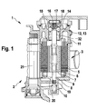
Figur 1- eine Schnittdarstellung einer elektromechanischen Bremse gemäß der Erfindung; und
Figur 2- einen Querschnitt eines Deckels eines Gehäuses der Bremse aus
Figur 1
- FIG. 1
- a sectional view of an electromechanical brake according to the invention; and
- FIG. 2
- a cross section of a lid of a housing of the brake
FIG. 1 ,
Die in der Zeichnung dargestellte, insgesamt mit 1 bezeichnete erfindungsgemäße Bremse ist eine Scheibenbremse. Sie weist eine elektromechanische Betätigungseinrichtung 2 mit einem Elektromotor 3, einem noch zu erläuternden mehrstufigen Zahnrad- und Untersetzungsgetriebe und einem Zahnstangengetriebe oder einem sonstigen Rotations-/Tranlsations-Umsetzungsgetriebe auf. Der Elektromotor 3, das Untersetzungsgetriebe und das Rotations-/Translations-Umsetzungsgetriebe bilden eine elektromechanische Betätigungseinrichtung der Bremse 1. Der Elektromotor 3 weist einen Stator 5 mit Statorwicklungen 6 sowie einen Rotor 7 auf einer Motorwelle 8 auf. Der Elektromotor 3 ist ein elektronisch kommutierter Gleichstrommotor (bürstenloser BLDC-Motor), was allerdings nicht zwingend für die Erfindung ist. Der Elektromotor 3 ist in einem Gehäuse 9 untergebracht, in das der Stator 5 eingepresst oder in anderer Weise fixiert ist. Die Motorwelle 8 ist an einem Ende mit einem Loslager 10, d. h. mit Axialspiel im Gehäuse 9 drehbar gelagert. Im dargestellten und beschriebenen Ausführungsbeispiel wird ein Rollenlager als Loslager 10 verwendet.The illustrated in the drawing, generally designated 1 brake according to the invention is a disc brake. It has an
Auf der anderen Stirnseite ist das Gehäuse 9 mit einem Deckel 11 verschlossen, der beispielsweise aus Stahl oder einem Werkstoff vergleichbarer Festigkeit hergestellt ist. Der Deckel 11 bildet ein Lagerschild eines Festlagers 12 des Elektromotors 3. Als Festlager 12 ist im dargestellten und beschriebenen Ausführungsbeispiel der Erfindung ein Kugellager mit Kugeln 13 gewählt, die in einem Kugelkäfig 14 drehbar gehalten sind. Eine in ein durchgehendes Axialloch im Deckel 11 geschliffene, umlaufende Nut mit kreisförmigem Querschnitt bildet einen äußeren Lagerring 15 des Festlagers 12. Ein innerer Lagerring des Festlagers 12 ist in einer Radialebene zur Motorwelle 8 zweigeteilt: Eine Hälfte des inneren Lagerrings wird von einer an einer Ringstufe der Motorwelle 8 geschliffenen Lauffläche 16 mit kreisförmigem Querschnitt gebildet. Eine zweite Lauffläche 17 mit ebenfalls kreisförmigem Querschnitt ist an einer Mutter 18 ausgebildet, die auf die Motorwelle 8 aufgeschraubt ist. Die Lauffläche 16 der Motorwelle 8 und die Lauffläche 17 der Mutter 18 ergänzen sich zu einer umlaufenden Nut mit kreisförmigem Querschnitt und zum inneren Lagerring 16, 17 des Festlagers 12. Durch Drehen der Mutter 18 auf der Motorwelle 8 kann ein Lagerspiel eingestellt werden, die Mutter 18 ist beispielsweise mit einem Schraubensicherungslack gegen Verdrehen auf der Motorwelle 8 gesichert.On the other end, the
An Stelle der beschriebenen Lagerkonstruktion des Festlagers 12 kommen auch andere Drehlagerungen der Motorwelle 8 in dem das Lagerschild bildenden Deckel 11 in Betracht. Es kann beispielsweise ein Wälzlager auf die Motorwelle 8 aufgepresst und in eine Ringstufe im Axialloch im Deckel 11 eingesetzt und dort mit einem Sicherungsring gesichert sein (nicht dargestellt).In place of the described bearing construction of the fixed bearing 12, other rotary bearings of the
Ein mit der Motorwelle 8 ein drehfestes, beispielsweise durch Schleifen hergestelltes Ritzel 19 kämmt mit einem großen Zahnrad 20, das drehfest auf einer ersten Getriebewelle 21 ist. Der Getriebewelle 21 können weitere Getriebestufen und eine auf beliebige Art betätigte Zuspannmechanik für eine Radbremse folgen.A with the motor shaft 8 a non-rotatable, for example, produced by grinding
Das Gehäuse 9, in dem der Elektromotor 3 untergebracht ist, ist Teil eines im Übrigen nicht dargestellten Bremssattels der als Scheibenbremse ausgebildeten Bremse 1. Das Gehäuse 9 kann auch am Bremssattel angebracht sein. Im Gehäuse 9 ist nicht nur der Elektromotor 3, sondern die gesamte Betätigungseinrichtung einschließlich der nicht dargestellten Zuspannmechanik untergebracht. Der Bremssattel, von dem nur ein Bruchteil, nämlich das Gehäuse 9, dargestellt ist, ist in an sich bekannter Weise als Schwimmsattel ausgebildet, d. h. er ist quer zu einer nicht dargestellten Bremsscheibe verschieblich geführt. Dadurch wird in an sich bekannter Weise beim Drücken eines Reibbremsbelags gegen eine Seite der Bremsscheibe ein zweiter Reibbremsbelag, der auf der gegenüberliegenden Seite der Bremsscheibe im Bremssattel angeordnet ist, gegen die andere Seite der Bremsscheibe gedrückt, so dass die Bremsscheibe auf beiden Seiten gebremst wird.The
Wie in
Ist der Rollenkäfig 33 in seine Ausgangsstellung zurück gedreht und sind die Rollen 32 durch die Federelemente 34 von der Motorwelle 8 abgehoben, ist der Freilauf 31 ausgeschaltet und die Motorwelle 8 in beiden Drehrichtungen frei drehbar.If the
Zum Drehen des Rollenkäfigs 33 und damit zum Einschalten des Freilaufs 31 weist der Freilauf 31 einen Elektromagneten 36 mit einer Wicklung 37 und einem Anker 38 auf. Ein Gehäuse 39 des Elektromagneten 36 ist einstückig mit dem Deckel 11 des Gehäuses 9 des Elektromotors 3. Ein Deckel 40, der das Gehäuse 39 des Elektromagneten 36 verschließt, bildet ein Joch des Elektromagneten 36, das den magnetischen Fluss schließt. Der Elektromagnet 36 schaltet den Freilauf 31 über einen Stößel 41, der tangential zum Rollenkäfig 33 des Freilaufs 31 angeordnet ist. Der Stößel 41 greift an einem radial nach außen vom Rollenkäfig 33 abstehenden Nocken 42 an, gegen dessen gegenüber liegende Seite ein Federelement 43 in Form einer Schraubendruckfeder drückt, die in einer Tasche des Deckels 11 außerhalb des Rollenkäfigs 33 untergebracht ist und die sich im Deckel 11 abstützt. Durch Bestromen der Spule 37 des Elektromagneten 36 wird der Anker 38 angezogen und drückt über den Stößel 41 gegen den Nocken 42 des Rollenkäfigs 33 des Freilaufs 31. Der Rollenkäfig 33 wird dadurch wie oben beschrieben in die eingeschaltete Stellung gedreht. Die Bremse 1 kann in der eingeschalteten Stellung des Freilaufs 31 weiter zugespannt, nicht jedoch gelöst werden. Ist oder wird die Bremse 1 bei eingeschaltetem Freilauf 31 betätigt, wird dadurch eine mechanische Spannung aufgebaut, die die Rollen 32 des Freilaufs 31 zwischen der Motorwelle 8 und dem Deckel 11 festgeklemmt hält, auch wenn der Elektromagnet 36 nicht mehr bestromt wird. Die Bremse 1 wird dadurch auch stromlos in der betätigten Stellung gehalten und kann dadurch als Feststellbremse verwendet werden. Zum Lösen wird die betätigte Bremse 1 mit dem Elektromotor 3 zugespannt, wodurch sich die mechanische Vorspannung löst, so dass das Federelement 43 den Rollenkäfig 33 des Freilaufs 31 in die ausgeschaltete Stellung zurück dreht. Die Motorwelle 8 ist jetzt frei drehbar, die Bremse 1 kann gelöst und als Betriebsbremse benützt werden. Der Deckel 11 mit den Taschen 35 für die Rollen 32, der mit den Rollen 32 zusammen wirkt und bei eingeschaltetem Freilauf 31 zusammen mit den Rollen 32 die Motorwelle 8 gegen Drehung in Löserichtung der Bremse 1 sperrt, bildet Teil einer Sperrung des Freilaufs 31.To rotate the
Der Deckel 11 des Gehäuses 9 enthält alle elektrischen Leitungen sowohl des Elektromotors 3 als auch des Elektromagneten 36, die elektrischen Leitungen sind in einem oder mehreren, in der Zeichnung nicht sichtbaren elektrischen Steckern zusammen geführt. Das hat den Vorteil eines einfachen elektrischen Anschlusses der elektrischen Bauteile der erfindungsgemäßen Bremse 1.The
Claims (7)
- Electromechanical brake, comprising an electric motor (3) with a housing (9) in which a motor shaft (8), which bears a rotor (7), is rotatably mounted and to one face end of which a cover (11) is attached, a rotation/translation conversion mechanism, a friction brake pad which, for the actuation of the brake (1), can be pressed against a brake body by the electric motor (3) by way of the rotation/translation conversion mechanism, and a switchable freewheel clutch (31) having clamping or blocking elements (32) which are arranged in an annular intermediate space between the motor shaft (8) and the cover (11) so as to be distributed around the motor shaft (8) such that the freewheel clutch (31), when in an activated position, permits a rotation of the motor shaft (8) of the electric motor (3) in the brake-application direction of the brake (1) and blocks a rotation in the release direction of the brake (1), wherein the cover (11) forms a bearing support for the motor shaft (8) of the electric motor (3), and wherein the freewheel clutch (31) is accommodated on or in the cover (11).
- Electromechanical brake according to Claim 1, characterized in that the cover (11) forms a bearing ring (15) for a bearing (12) of the motor shaft (8).
- Electromechanical brake according to Claim 1, characterized in that at least one part (16) of a bearing ring (16, 17) of the bearing (12) of the motor shaft (8) is an integral constituent part of the motor shaft (8), and in that said part (16) of the bearing ring (16, 17) fixes the motor shaft (8) in an axial direction.
- Electromechanical brake according to Claim 1, characterized in that the cover (11) is part of a blocking means of the freewheel clutch (31).
- Electromechanical brake according to Claim 1, characterized in that the cover (11) has all of the electrical connections of the electric motor (3) and of the freewheel clutch (31).
- Electromechanical brake according to Claim 1, characterized in that the brake (1) is a disk brake, and in that the housing (9) is part of a brake caliper of the brake (1).
- Electromechanical brake according to Claim 1, characterized in that the cover (11) forms a housing (39) for the freewheel clutch (31).
Applications Claiming Priority (2)
| Application Number | Priority Date | Filing Date | Title |
|---|---|---|---|
| DE102005035607A DE102005035607A1 (en) | 2005-07-29 | 2005-07-29 | Electromechanical brake |
| PCT/EP2006/062910 WO2007012515A1 (en) | 2005-07-29 | 2006-06-06 | Electromechanical brake |
Publications (2)
| Publication Number | Publication Date |
|---|---|
| EP1912840A1 EP1912840A1 (en) | 2008-04-23 |
| EP1912840B1 true EP1912840B1 (en) | 2014-10-22 |
Family
ID=36808781
Family Applications (1)
| Application Number | Title | Priority Date | Filing Date |
|---|---|---|---|
| EP06763514.4A Active EP1912840B1 (en) | 2005-07-29 | 2006-06-06 | Electromechanical brake |
Country Status (6)
| Country | Link |
|---|---|
| US (1) | US8020675B2 (en) |
| EP (1) | EP1912840B1 (en) |
| JP (1) | JP4886780B2 (en) |
| CN (1) | CN101233031B (en) |
| DE (1) | DE102005035607A1 (en) |
| WO (1) | WO2007012515A1 (en) |
Cited By (1)
| Publication number | Priority date | Publication date | Assignee | Title |
|---|---|---|---|---|
| DE102022121851A1 (en) | 2022-08-30 | 2024-02-29 | Schaeffler Technologies AG & Co. KG | Bearing arrangement with switchable freewheel, linear actuator and method for operating a linear actuator |
Families Citing this family (10)
| Publication number | Priority date | Publication date | Assignee | Title |
|---|---|---|---|---|
| DE102006000746A1 (en) * | 2006-01-04 | 2007-07-05 | Robert Bosch Gmbh | Adjustable free-wheel for motor vehicle, has outer ring and blocking device cage designed as rotor and stator, where cage has coils so that cage is rotatable with respect to ring in switched-on and off-position by energizing coils |
| DK2193283T3 (en) * | 2007-09-19 | 2013-06-10 | Skf Ab | locking device |
| DE102008059012A1 (en) * | 2008-11-26 | 2010-05-27 | Schaeffler Kg | Electromagnetic actuator for a hydraulic directional control valve and method for its assembly |
| DE102011002565A1 (en) * | 2010-02-16 | 2011-08-18 | Continental Teves AG & Co. OHG, 60488 | Actuation unit for an electromechanically actuated disc brake |
| JP6214230B2 (en) | 2013-06-11 | 2017-10-18 | Ntn株式会社 | Electric brake device |
| DE102013217048A1 (en) * | 2013-08-27 | 2015-03-05 | Zf Friedrichshafen Ag | Magnetic device for locking a gear selector lever of a vehicle in a predetermined position, method for producing a magnetic device and method for operating a magnetic device |
| DE102013020468A1 (en) | 2013-12-06 | 2015-06-11 | Lucas Automotive Gmbh | Electromechanically and hydraulically actuated motor vehicle brake with optional self-locking |
| DE102017107102B3 (en) * | 2017-04-03 | 2018-07-05 | Schaeffler Technologies AG & Co. KG | Backstop and transfer case with a backstop |
| US11964641B2 (en) * | 2021-07-13 | 2024-04-23 | ZF Active Safety US Inc. | Electronic parking brake |
| US20240218908A1 (en) * | 2023-01-04 | 2024-07-04 | Halliburton Energy Services, Inc. | Dynamically Engageable Electromechanical Brake |
Family Cites Families (13)
| Publication number | Priority date | Publication date | Assignee | Title |
|---|---|---|---|---|
| JPH062023Y2 (en) * | 1986-06-25 | 1994-01-19 | 有限会社シー・エス・ユー | Simple ball bearing |
| DE19652229A1 (en) | 1996-12-16 | 1998-06-18 | Bosch Gmbh Robert | Electromechanically operated brake |
| DE19807328C2 (en) * | 1998-02-20 | 2003-08-28 | Lucas Ind Plc | Electromechanically actuated disc brake |
| DE19859325A1 (en) * | 1998-12-22 | 2000-06-29 | Bosch Gmbh Robert | Method for operating an electromechanical wheel brake device |
| DE19945543A1 (en) * | 1999-09-23 | 2001-03-29 | Continental Teves Ag & Co Ohg | Actuating unit for an electromechanically actuated disc brake |
| JP4432004B2 (en) * | 1999-09-30 | 2010-03-17 | 日立オートモティブシステムズ株式会社 | Electric disc brake |
| JP2002340144A (en) * | 2001-05-11 | 2002-11-27 | Koyo Seiko Co Ltd | Pulley unit |
| DE10300404A1 (en) * | 2002-02-06 | 2003-08-14 | Barmag Barmer Maschf | Textile thread bobbin spool bearing, has inner ball race formed directly on and by the spindle shaft surface |
| DE50303381D1 (en) * | 2002-08-13 | 2006-06-22 | Continental Teves Ag & Co Ohg | METHOD FOR ACTUATING AN ELECTROMECHANICAL PARKING BRAKING DEVICE |
| JP2004092755A (en) * | 2002-08-30 | 2004-03-25 | Nsk Ltd | Assembly method of bearing device and the bearing device |
| DE10255192B4 (en) * | 2002-11-27 | 2015-03-19 | Robert Bosch Gmbh | Electromechanical brake |
| US6971485B1 (en) * | 2004-08-19 | 2005-12-06 | Robert Bosch Gmbh | Parking brake lock |
| DE102005055085B4 (en) * | 2005-09-29 | 2020-09-24 | Robert Bosch Gmbh | Combined service and parking brake device as well as a method for performing emergency braking |
-
2005
- 2005-07-29 DE DE102005035607A patent/DE102005035607A1/en not_active Withdrawn
-
2006
- 2006-06-06 WO PCT/EP2006/062910 patent/WO2007012515A1/en active Application Filing
- 2006-06-06 CN CN2006800276778A patent/CN101233031B/en not_active Expired - Fee Related
- 2006-06-06 EP EP06763514.4A patent/EP1912840B1/en active Active
- 2006-06-06 US US11/997,255 patent/US8020675B2/en not_active Expired - Fee Related
- 2006-06-06 JP JP2008523273A patent/JP4886780B2/en not_active Expired - Fee Related
Cited By (1)
| Publication number | Priority date | Publication date | Assignee | Title |
|---|---|---|---|---|
| DE102022121851A1 (en) | 2022-08-30 | 2024-02-29 | Schaeffler Technologies AG & Co. KG | Bearing arrangement with switchable freewheel, linear actuator and method for operating a linear actuator |
Also Published As
| Publication number | Publication date |
|---|---|
| CN101233031B (en) | 2012-07-18 |
| US20080217121A1 (en) | 2008-09-11 |
| EP1912840A1 (en) | 2008-04-23 |
| WO2007012515A1 (en) | 2007-02-01 |
| JP4886780B2 (en) | 2012-02-29 |
| DE102005035607A1 (en) | 2007-02-15 |
| JP2009503391A (en) | 2009-01-29 |
| CN101233031A (en) | 2008-07-30 |
| US8020675B2 (en) | 2011-09-20 |
Similar Documents
| Publication | Publication Date | Title |
|---|---|---|
| EP1912840B1 (en) | Electromechanical brake | |
| EP0900342B1 (en) | Electromotive braking device | |
| EP1032772B1 (en) | Magnetic brake and electromechanical brake device with a magnetic brake | |
| EP2377736B1 (en) | Ball screw for a motor vehicle brake and motor vehicle brake | |
| DE69707674T2 (en) | ELECTROMAGNETICALLY RELEASABLE SAFETY FRICTION BRAKE | |
| EP2041446B1 (en) | Positive-fit freewheel mechanism that can be electromechanically actuated, electromechanical brake with a freewheel mechanism of this type for a motor vehicle and method for adjusting the play in a brake of this type | |
| WO2005111458A1 (en) | Disengaging free-wheel and electromechanical vehicle brake having a disengaging free-wheel | |
| EP3077697B1 (en) | Motor vehicle brake which can be activated electromechanically and hydraulically and has optional self-locking | |
| DE112011103541T5 (en) | Electric linear motion actuator and electric disc brake system | |
| WO2008090197A2 (en) | Brake for a linearly and rotatorily displaceable shaft | |
| EP1971791A1 (en) | Selective freewheeling mechanism and electromechanical vehicle brake comprising a selective freewheeling mechanism | |
| EP1706298B1 (en) | Electromechanically actuated parking brake | |
| DE102011086152B4 (en) | Braking device | |
| DE60209549T2 (en) | PARKING BRAKE ASSEMBLY IN AN ELECTRICALLY OPERATED BRAKE | |
| DE10255192A1 (en) | Electromechanical brake | |
| DE10234848A1 (en) | Electromechanical brake for vehicle, has switchable idler that allows operation of working brake and inhibits its release when switched on and allows operation and release of working brake when switched off | |
| DE19719990A1 (en) | Brake for electric motor, esp. for moving control elements in motor vehicle | |
| EP1941177B1 (en) | Disc brake with an electric motor actuator and an emergency releasing device | |
| EP1307664B1 (en) | Disc brake that is actuated by means of a band brake device | |
| DE10227828B4 (en) | Electrically actuated motor vehicle disc brake | |
| DE102007012074A1 (en) | Vehicle brake, has electromagnetic operating mechanism, particularly for operating in emergency release, adjustment or park brake function, and operating mechanism has spindle | |
| DE10222101A1 (en) | An electromagnetic brake has a multi-segment brake ring which is reduced in diameter by release of the magnet current and employment of springs | |
| DE20116131U1 (en) | Spring-loaded brake for bikes without or with gearless travel drives | |
| DE102023200503A1 (en) | Electromechanical brake | |
| DE19803341A1 (en) | Disc brake with electromechanical actuation unit |
Legal Events
| Date | Code | Title | Description |
|---|---|---|---|
| PUAI | Public reference made under article 153(3) epc to a published international application that has entered the european phase |
Free format text: ORIGINAL CODE: 0009012 |
|
| 17P | Request for examination filed |
Effective date: 20080229 |
|
| AK | Designated contracting states |
Kind code of ref document: A1 Designated state(s): AT BE BG CH CY CZ DE DK EE ES FI FR GB GR HU IE IS IT LI LT LU LV MC NL PL PT RO SE SI SK TR |
|
| 17Q | First examination report despatched |
Effective date: 20081230 |
|
| DAX | Request for extension of the european patent (deleted) | ||
| RIC1 | Information provided on ipc code assigned before grant |
Ipc: B60T 13/74 20060101AFI20140605BHEP Ipc: F16D 65/18 20060101ALI20140605BHEP |
|
| GRAP | Despatch of communication of intention to grant a patent |
Free format text: ORIGINAL CODE: EPIDOSNIGR1 |
|
| INTG | Intention to grant announced |
Effective date: 20140728 |
|
| GRAS | Grant fee paid |
Free format text: ORIGINAL CODE: EPIDOSNIGR3 |
|
| GRAA | (expected) grant |
Free format text: ORIGINAL CODE: 0009210 |
|
| AK | Designated contracting states |
Kind code of ref document: B1 Designated state(s): AT BE BG CH CY CZ DE DK EE ES FI FR GB GR HU IE IS IT LI LT LU LV MC NL PL PT RO SE SI SK TR |
|
| REG | Reference to a national code |
Ref country code: GB Ref legal event code: FG4D Free format text: NOT ENGLISH |
|
| REG | Reference to a national code |
Ref country code: CH Ref legal event code: EP |
|
| REG | Reference to a national code |
Ref country code: AT Ref legal event code: REF Ref document number: 692472 Country of ref document: AT Kind code of ref document: T Effective date: 20141115 |
|
| REG | Reference to a national code |
Ref country code: IE Ref legal event code: FG4D Free format text: LANGUAGE OF EP DOCUMENT: GERMAN |
|
| REG | Reference to a national code |
Ref country code: DE Ref legal event code: R096 Ref document number: 502006014031 Country of ref document: DE Effective date: 20141204 |
|
| REG | Reference to a national code |
Ref country code: NL Ref legal event code: VDEP Effective date: 20141022 |
|
| REG | Reference to a national code |
Ref country code: LT Ref legal event code: MG4D |
|
| PG25 | Lapsed in a contracting state [announced via postgrant information from national office to epo] |
Ref country code: NL Free format text: LAPSE BECAUSE OF FAILURE TO SUBMIT A TRANSLATION OF THE DESCRIPTION OR TO PAY THE FEE WITHIN THE PRESCRIBED TIME-LIMIT Effective date: 20141022 Ref country code: LT Free format text: LAPSE BECAUSE OF FAILURE TO SUBMIT A TRANSLATION OF THE DESCRIPTION OR TO PAY THE FEE WITHIN THE PRESCRIBED TIME-LIMIT Effective date: 20141022 Ref country code: IS Free format text: LAPSE BECAUSE OF FAILURE TO SUBMIT A TRANSLATION OF THE DESCRIPTION OR TO PAY THE FEE WITHIN THE PRESCRIBED TIME-LIMIT Effective date: 20150222 Ref country code: ES Free format text: LAPSE BECAUSE OF FAILURE TO SUBMIT A TRANSLATION OF THE DESCRIPTION OR TO PAY THE FEE WITHIN THE PRESCRIBED TIME-LIMIT Effective date: 20141022 Ref country code: FI Free format text: LAPSE BECAUSE OF FAILURE TO SUBMIT A TRANSLATION OF THE DESCRIPTION OR TO PAY THE FEE WITHIN THE PRESCRIBED TIME-LIMIT Effective date: 20141022 Ref country code: PT Free format text: LAPSE BECAUSE OF FAILURE TO SUBMIT A TRANSLATION OF THE DESCRIPTION OR TO PAY THE FEE WITHIN THE PRESCRIBED TIME-LIMIT Effective date: 20150223 |
|
| PG25 | Lapsed in a contracting state [announced via postgrant information from national office to epo] |
Ref country code: PL Free format text: LAPSE BECAUSE OF FAILURE TO SUBMIT A TRANSLATION OF THE DESCRIPTION OR TO PAY THE FEE WITHIN THE PRESCRIBED TIME-LIMIT Effective date: 20141022 Ref country code: GR Free format text: LAPSE BECAUSE OF FAILURE TO SUBMIT A TRANSLATION OF THE DESCRIPTION OR TO PAY THE FEE WITHIN THE PRESCRIBED TIME-LIMIT Effective date: 20150123 Ref country code: LV Free format text: LAPSE BECAUSE OF FAILURE TO SUBMIT A TRANSLATION OF THE DESCRIPTION OR TO PAY THE FEE WITHIN THE PRESCRIBED TIME-LIMIT Effective date: 20141022 Ref country code: SE Free format text: LAPSE BECAUSE OF FAILURE TO SUBMIT A TRANSLATION OF THE DESCRIPTION OR TO PAY THE FEE WITHIN THE PRESCRIBED TIME-LIMIT Effective date: 20141022 Ref country code: CY Free format text: LAPSE BECAUSE OF FAILURE TO SUBMIT A TRANSLATION OF THE DESCRIPTION OR TO PAY THE FEE WITHIN THE PRESCRIBED TIME-LIMIT Effective date: 20141022 |
|
| REG | Reference to a national code |
Ref country code: DE Ref legal event code: R097 Ref document number: 502006014031 Country of ref document: DE |
|
| PG25 | Lapsed in a contracting state [announced via postgrant information from national office to epo] |
Ref country code: DK Free format text: LAPSE BECAUSE OF FAILURE TO SUBMIT A TRANSLATION OF THE DESCRIPTION OR TO PAY THE FEE WITHIN THE PRESCRIBED TIME-LIMIT Effective date: 20141022 Ref country code: CZ Free format text: LAPSE BECAUSE OF FAILURE TO SUBMIT A TRANSLATION OF THE DESCRIPTION OR TO PAY THE FEE WITHIN THE PRESCRIBED TIME-LIMIT Effective date: 20141022 Ref country code: RO Free format text: LAPSE BECAUSE OF FAILURE TO SUBMIT A TRANSLATION OF THE DESCRIPTION OR TO PAY THE FEE WITHIN THE PRESCRIBED TIME-LIMIT Effective date: 20141022 Ref country code: SK Free format text: LAPSE BECAUSE OF FAILURE TO SUBMIT A TRANSLATION OF THE DESCRIPTION OR TO PAY THE FEE WITHIN THE PRESCRIBED TIME-LIMIT Effective date: 20141022 Ref country code: EE Free format text: LAPSE BECAUSE OF FAILURE TO SUBMIT A TRANSLATION OF THE DESCRIPTION OR TO PAY THE FEE WITHIN THE PRESCRIBED TIME-LIMIT Effective date: 20141022 |
|
| PLBE | No opposition filed within time limit |
Free format text: ORIGINAL CODE: 0009261 |
|
| STAA | Information on the status of an ep patent application or granted ep patent |
Free format text: STATUS: NO OPPOSITION FILED WITHIN TIME LIMIT |
|
| PG25 | Lapsed in a contracting state [announced via postgrant information from national office to epo] |
Ref country code: IT Free format text: LAPSE BECAUSE OF FAILURE TO SUBMIT A TRANSLATION OF THE DESCRIPTION OR TO PAY THE FEE WITHIN THE PRESCRIBED TIME-LIMIT Effective date: 20141022 |
|
| 26N | No opposition filed |
Effective date: 20150723 |
|
| PG25 | Lapsed in a contracting state [announced via postgrant information from national office to epo] |
Ref country code: MC Free format text: LAPSE BECAUSE OF FAILURE TO SUBMIT A TRANSLATION OF THE DESCRIPTION OR TO PAY THE FEE WITHIN THE PRESCRIBED TIME-LIMIT Effective date: 20141022 |
|
| REG | Reference to a national code |
Ref country code: CH Ref legal event code: PL |
|
| GBPC | Gb: european patent ceased through non-payment of renewal fee |
Effective date: 20150606 |
|
| PG25 | Lapsed in a contracting state [announced via postgrant information from national office to epo] |
Ref country code: LU Free format text: LAPSE BECAUSE OF FAILURE TO SUBMIT A TRANSLATION OF THE DESCRIPTION OR TO PAY THE FEE WITHIN THE PRESCRIBED TIME-LIMIT Effective date: 20150606 Ref country code: SI Free format text: LAPSE BECAUSE OF FAILURE TO SUBMIT A TRANSLATION OF THE DESCRIPTION OR TO PAY THE FEE WITHIN THE PRESCRIBED TIME-LIMIT Effective date: 20141022 |
|
| REG | Reference to a national code |
Ref country code: IE Ref legal event code: MM4A |
|
| REG | Reference to a national code |
Ref country code: FR Ref legal event code: ST Effective date: 20160229 |
|
| PG25 | Lapsed in a contracting state [announced via postgrant information from national office to epo] |
Ref country code: LI Free format text: LAPSE BECAUSE OF NON-PAYMENT OF DUE FEES Effective date: 20150630 Ref country code: GB Free format text: LAPSE BECAUSE OF NON-PAYMENT OF DUE FEES Effective date: 20150606 Ref country code: CH Free format text: LAPSE BECAUSE OF NON-PAYMENT OF DUE FEES Effective date: 20150630 Ref country code: IE Free format text: LAPSE BECAUSE OF NON-PAYMENT OF DUE FEES Effective date: 20150606 |
|
| PG25 | Lapsed in a contracting state [announced via postgrant information from national office to epo] |
Ref country code: FR Free format text: LAPSE BECAUSE OF NON-PAYMENT OF DUE FEES Effective date: 20150630 |
|
| REG | Reference to a national code |
Ref country code: AT Ref legal event code: MM01 Ref document number: 692472 Country of ref document: AT Kind code of ref document: T Effective date: 20150606 |
|
| PG25 | Lapsed in a contracting state [announced via postgrant information from national office to epo] |
Ref country code: AT Free format text: LAPSE BECAUSE OF NON-PAYMENT OF DUE FEES Effective date: 20150606 |
|
| PG25 | Lapsed in a contracting state [announced via postgrant information from national office to epo] |
Ref country code: BG Free format text: LAPSE BECAUSE OF FAILURE TO SUBMIT A TRANSLATION OF THE DESCRIPTION OR TO PAY THE FEE WITHIN THE PRESCRIBED TIME-LIMIT Effective date: 20141022 Ref country code: HU Free format text: LAPSE BECAUSE OF FAILURE TO SUBMIT A TRANSLATION OF THE DESCRIPTION OR TO PAY THE FEE WITHIN THE PRESCRIBED TIME-LIMIT; INVALID AB INITIO Effective date: 20060606 |
|
| PG25 | Lapsed in a contracting state [announced via postgrant information from national office to epo] |
Ref country code: BE Free format text: LAPSE BECAUSE OF NON-PAYMENT OF DUE FEES Effective date: 20150630 |
|
| PG25 | Lapsed in a contracting state [announced via postgrant information from national office to epo] |
Ref country code: TR Free format text: LAPSE BECAUSE OF FAILURE TO SUBMIT A TRANSLATION OF THE DESCRIPTION OR TO PAY THE FEE WITHIN THE PRESCRIBED TIME-LIMIT Effective date: 20141022 |
|
| REG | Reference to a national code |
Ref country code: DE Ref legal event code: R084 Ref document number: 502006014031 Country of ref document: DE |
|
| PGFP | Annual fee paid to national office [announced via postgrant information from national office to epo] |
Ref country code: DE Payment date: 20230817 Year of fee payment: 18 |