EP1911997A2 - Automobile gearshift indication apparatus - Google Patents
Automobile gearshift indication apparatus Download PDFInfo
- Publication number
- EP1911997A2 EP1911997A2 EP07254015A EP07254015A EP1911997A2 EP 1911997 A2 EP1911997 A2 EP 1911997A2 EP 07254015 A EP07254015 A EP 07254015A EP 07254015 A EP07254015 A EP 07254015A EP 1911997 A2 EP1911997 A2 EP 1911997A2
- Authority
- EP
- European Patent Office
- Prior art keywords
- gearshift
- indication
- gearshift indication
- automobile
- time
- Prior art date
- Legal status (The legal status is an assumption and is not a legal conclusion. Google has not performed a legal analysis and makes no representation as to the accuracy of the status listed.)
- Granted
Links
- 230000005540 biological transmission Effects 0.000 claims description 29
- 230000001133 acceleration Effects 0.000 claims description 21
- 238000001514 detection method Methods 0.000 claims description 17
- 230000001934 delay Effects 0.000 claims description 3
- 239000000446 fuel Substances 0.000 description 13
- 238000005286 illumination Methods 0.000 description 13
- 238000005516 engineering process Methods 0.000 description 7
- 230000002411 adverse Effects 0.000 description 5
- 238000002485 combustion reaction Methods 0.000 description 4
- 230000006870 function Effects 0.000 description 3
- 238000000034 method Methods 0.000 description 3
- 230000004397 blinking Effects 0.000 description 2
- 230000002596 correlated effect Effects 0.000 description 2
- 230000007423 decrease Effects 0.000 description 2
- 230000000694 effects Effects 0.000 description 2
- 230000002457 bidirectional effect Effects 0.000 description 1
- 239000003086 colorant Substances 0.000 description 1
- 230000003247 decreasing effect Effects 0.000 description 1
- 230000003111 delayed effect Effects 0.000 description 1
- 238000013461 design Methods 0.000 description 1
- 238000009434 installation Methods 0.000 description 1
- 239000004973 liquid crystal related substance Substances 0.000 description 1
- 238000012986 modification Methods 0.000 description 1
- 230000004048 modification Effects 0.000 description 1
- 238000011017 operating method Methods 0.000 description 1
- 238000012545 processing Methods 0.000 description 1
- 238000004904 shortening Methods 0.000 description 1
- XLYOFNOQVPJJNP-UHFFFAOYSA-N water Substances O XLYOFNOQVPJJNP-UHFFFAOYSA-N 0.000 description 1
Images




Classifications
-
- F—MECHANICAL ENGINEERING; LIGHTING; HEATING; WEAPONS; BLASTING
- F16—ENGINEERING ELEMENTS AND UNITS; GENERAL MEASURES FOR PRODUCING AND MAINTAINING EFFECTIVE FUNCTIONING OF MACHINES OR INSTALLATIONS; THERMAL INSULATION IN GENERAL
- F16H—GEARING
- F16H63/00—Control outputs from the control unit to change-speed- or reversing-gearings for conveying rotary motion or to other devices than the final output mechanism
- F16H63/40—Control outputs from the control unit to change-speed- or reversing-gearings for conveying rotary motion or to other devices than the final output mechanism comprising signals other than signals for actuating the final output mechanisms
- F16H63/42—Ratio indicator devices
-
- F—MECHANICAL ENGINEERING; LIGHTING; HEATING; WEAPONS; BLASTING
- F16—ENGINEERING ELEMENTS AND UNITS; GENERAL MEASURES FOR PRODUCING AND MAINTAINING EFFECTIVE FUNCTIONING OF MACHINES OR INSTALLATIONS; THERMAL INSULATION IN GENERAL
- F16H—GEARING
- F16H63/00—Control outputs from the control unit to change-speed- or reversing-gearings for conveying rotary motion or to other devices than the final output mechanism
- F16H63/40—Control outputs from the control unit to change-speed- or reversing-gearings for conveying rotary motion or to other devices than the final output mechanism comprising signals other than signals for actuating the final output mechanisms
- F16H63/42—Ratio indicator devices
- F16H2063/426—Ratio indicator devices with means for advising the driver for proper shift action, e.g. prompting the driver with allowable selection range of ratios
-
- F—MECHANICAL ENGINEERING; LIGHTING; HEATING; WEAPONS; BLASTING
- F16—ENGINEERING ELEMENTS AND UNITS; GENERAL MEASURES FOR PRODUCING AND MAINTAINING EFFECTIVE FUNCTIONING OF MACHINES OR INSTALLATIONS; THERMAL INSULATION IN GENERAL
- F16H—GEARING
- F16H59/00—Control inputs to control units of change-speed- or reversing-gearings for conveying rotary motion
- F16H59/14—Inputs being a function of torque or torque demand
-
- F—MECHANICAL ENGINEERING; LIGHTING; HEATING; WEAPONS; BLASTING
- F16—ENGINEERING ELEMENTS AND UNITS; GENERAL MEASURES FOR PRODUCING AND MAINTAINING EFFECTIVE FUNCTIONING OF MACHINES OR INSTALLATIONS; THERMAL INSULATION IN GENERAL
- F16H—GEARING
- F16H59/00—Control inputs to control units of change-speed- or reversing-gearings for conveying rotary motion
- F16H59/14—Inputs being a function of torque or torque demand
- F16H59/18—Inputs being a function of torque or torque demand dependent on the position of the accelerator pedal
-
- F—MECHANICAL ENGINEERING; LIGHTING; HEATING; WEAPONS; BLASTING
- F16—ENGINEERING ELEMENTS AND UNITS; GENERAL MEASURES FOR PRODUCING AND MAINTAINING EFFECTIVE FUNCTIONING OF MACHINES OR INSTALLATIONS; THERMAL INSULATION IN GENERAL
- F16H—GEARING
- F16H59/00—Control inputs to control units of change-speed- or reversing-gearings for conveying rotary motion
- F16H59/48—Inputs being a function of acceleration
-
- F—MECHANICAL ENGINEERING; LIGHTING; HEATING; WEAPONS; BLASTING
- F16—ENGINEERING ELEMENTS AND UNITS; GENERAL MEASURES FOR PRODUCING AND MAINTAINING EFFECTIVE FUNCTIONING OF MACHINES OR INSTALLATIONS; THERMAL INSULATION IN GENERAL
- F16H—GEARING
- F16H61/00—Control functions within control units of change-speed- or reversing-gearings for conveying rotary motion ; Control of exclusively fluid gearing, friction gearing, gearings with endless flexible members or other particular types of gearing
- F16H61/02—Control functions within control units of change-speed- or reversing-gearings for conveying rotary motion ; Control of exclusively fluid gearing, friction gearing, gearings with endless flexible members or other particular types of gearing characterised by the signals used
- F16H61/0202—Control functions within control units of change-speed- or reversing-gearings for conveying rotary motion ; Control of exclusively fluid gearing, friction gearing, gearings with endless flexible members or other particular types of gearing characterised by the signals used the signals being electric
- F16H61/0204—Control functions within control units of change-speed- or reversing-gearings for conveying rotary motion ; Control of exclusively fluid gearing, friction gearing, gearings with endless flexible members or other particular types of gearing characterised by the signals used the signals being electric for gearshift control, e.g. control functions for performing shifting or generation of shift signal
- F16H61/0213—Control functions within control units of change-speed- or reversing-gearings for conveying rotary motion ; Control of exclusively fluid gearing, friction gearing, gearings with endless flexible members or other particular types of gearing characterised by the signals used the signals being electric for gearshift control, e.g. control functions for performing shifting or generation of shift signal characterised by the method for generating shift signals
Definitions
- gearshift map having gearshift lines (gear switch lines) for obtaining an optimum gear for the vehicle speed and the accelerator opening degree is stored in a controller, and a gear switching operation is automatically performed according to the gearshift map.
- various programs including at least a program for executing gearshift indication control that indicates an appropriate gear position selection of the manual transmission 2 for achieving improved fuel efficiency according to the running state of the automobile, or the like, are stored in the ROM 43, in addition to various programs for executing control related to basic driving of the automobile.
- the specific content of this gearshift indication control will be described below.
- FIG 5B shows a state in which the present gear position is fourth gear, and the target gear position is third gear.
- FIG 5B shows the display state when, in a state in which the automobile is running with the present gear position of the manual transmission 2 set to fourth gear, the driving state has changed from point PC to point PD in FIG 4.
- the gearshift indication permission timer is a delay timer that starts a count at the point in time that the above gearshift indication condition is established and the time counted by the above lamp off timer has elapsed (the point of time that an AND condition of these has been established). Due to elapsing of the time counted by the gearshift indication permission timer, a gearshift indication operation (illumination of the above lamps 11 and 12 and display by the target gear position display portion 13b) according to the gearshift indication condition are permitted.
- Step ST1 the routine moves directly to the operations from Step ST5 onward.
- gearshift indication is performed by illumination of the upshift lamp 11 or the like.
- time I the time counted by the gearshift indication permission timer elapses after delaying for a delay time E
- gearshift indication is performed by illumination of the upshift lamp 11 or the like.
- gearshift indication control for an upshift was described as gearshift indication control, but likewise in the case of a downshift, a configuration may be adopted in which the count value (Ton) of the gearshift indication permission timer is changed according to the accelerator opening degree.
- the count value of the gearshift indication permission timer (in the above embodiments, 2 sec., 1.5 sec., 1 sec.) and the value of the accelerator opening degree for determining the count value (in the above embodiments, 20%, 80%) are not limited to the values stated above, and can be set as desired.
- the gearshift lines of the gearshift map are not limited to those shown in FIG 4, and can be set as desired.
Landscapes
- Engineering & Computer Science (AREA)
- General Engineering & Computer Science (AREA)
- Mechanical Engineering (AREA)
- Control Of Transmission Device (AREA)
- Arrangement And Mounting Of Devices That Control Transmission Of Motive Force (AREA)
Abstract
Description
- The present invention relates to a gearshift indication apparatus that performs gearshift indication to a driver to instruct the driver to shift to a gear appropriate to a running state in an automobile equipped with a manual transmission. More specifically, the present invention relates to improvement of a gearshift indication apparatus configured so as to perform gearshift indication delay control in order to avoid bothering a driver by frequently producing a gearshift indication (for example, illumination of an indicator lamp) during a short period of time.
- Conventionally, in order for an automobile to obtain a necessary running torque or vehicle speed, engine (internal combustion engine) output is shifted with a transmission and transmitted to the wheels of the vehicle, and an optimum gear for the running state is generally determined according to the vehicle speed, engine load (for example, the accelerator opening degree), or the like. For example, in an automobile equipped with an automatic transmission, a gearshift map having gearshift lines (gear switch lines) for obtaining an optimum gear for the vehicle speed and the accelerator opening degree is stored in a controller, and a gear switching operation is automatically performed according to the gearshift map.
- However, in an automobile equipped with a manual transmission, because the driver sets the gear as desired, there are large differences between individual people with respect to selection of the gear and the timing of the shift operation, so there is a high possibility that the automobile is running with the gear set to a different gear than the optimum gear. For example, in an operation to increase the gear (an upshift operation), when the gear is set to a lower gear (low gear side) than the optimum gear, worsened fuel efficiency results, and conversely, when the gear is set to a higher gear (high gear side) than the optimum gear, adequate acceleration performance is not obtained.
- In order to address such problems, for example,
JP 2003-19912A JP H05-180339A - Specifically, a gearshift map approximately the same as the gearshift map in the automatic transmission described above is stored in a controller, and when the gear set by the driver is different from the optimum gear obtained from the running state, the gearshift indication apparatus visually indicates to the driver that an upshift or a downshift should be performed according to the gearshift map. For example, a display portion for prompting an upshift or a downshift of the transmission is provided in a combination meter inside the vehicle cabin, and shift change advice is performed by illuminating the display portion according to the running state. This sort of gearshift indication apparatus is not limited to the above manual transmission, and is applicable also in an automobile provided with an automatic transmission having a manual gearshift function (a transmission capable of so-called sequential shifting).
- However, when this sort of gearshift apparatus is provided, there is a possibility that the gearshift indication will be frequently produced during a short time period, and in this state the gearshift operation is bothersome to the driver. These sorts of circumstances notably occur when, for example, accelerating in a state with the accelerator opened a small amount after the automobile begins moving, or when running the automobile on a downward sloping street after the automobile begins moving, or the like.
- In view of these points, it has been proposed to provide a delay timer that starts a count after establishment of a condition for execution of a gearshift indication up to then, i.e., after it has been judged that a gearshift operation is necessary in order to obtain an optimum gear according to the above gearshift map, and to perform gearshift indication delay control such that an actual gearshift indication is executed after a time period counted by this delay timer has elapsed. With this configuration, it is possible to avoid a circumstance in which the driver performs a gearshift operation according to a gearshift indication and then immediately afterward a subsequent gearshift indication is displayed, and thus the driver is not bothered.
- However, when performing the gearshift indication delay control described above, there are problems as stated below.
- In the above gearshift map for gearshift indication performed by the above gearshift indication apparatus, for example, a plurality of gearshift lines are plotted as shown in FIG 4, and with these gearshift lines, in a circumstance in which the accelerator is open to a small degree, the gear is increased even when the vehicle speed is comparatively low. When the accelerator is open to a small degree, it is possible to determine that the driver is not demanding fast acceleration, and so the gear is increased in this case in order to achieve an improvement in fuel efficiency by using a high gear. Therefore, in a region of the gearshift map in which the accelerator is open to a small degree, there is a small gap between each of the gearshift lines (the gearshift lines are closely spaced).
- On the other hand, when the accelerator is open to a large degree, a low gear is maintained without switching until the vehicle speed becomes comparatively high. When the accelerator is open to a large degree, it is possible to determine that the driver is demanding fast acceleration, and so the demand for fast acceleration is met by maintaining a low gear. Therefore, in a region of the gearshift map in which the accelerator is open to a large degree, there is a large gap between each of the gearshift lines (the gearshift lines are widely spaced).
- When the above gearshift indication delay control is performed for a gearshift indication apparatus that performs gearshift indication according to a gearshift map in this manner, it is possible to avoid frequently producing a gearshift indication as described above in a circumstance in which the accelerator is open to a small degree, and so the driver is not bothered.
- However, in a circumstance in which the accelerator is open to a large degree, there is a possibility that a delay in the upshift indication will be caused by the gearshift indication delay control and thus a low gear will be maintained more than is necessary, and there is a risk that the delay in the upshift operation will be accompanied by the number of engine revolutions increasing to more than is necessary. Such a circumstance invites worsened fuel efficiency, and adversely affects engine longevity.
- The present invention was made in consideration of the foregoing points, and it is an object thereof to provide, for an automobile gearshift indication apparatus that performs the above gearshift indication delay control, a configuration in which a gearshift indication is provided to the driver at a timing appropriate to the size of the engine load, the engine load being represented by the accelerator opening degree.
- The present invention provides an automobile gearshift indication apparatus that is used in an automobile equipped with a transmission capable of manual operation, and when a gearshift indication condition has been established in which an optimum gear of the transmission desired according to a driving state of the automobile is different from a gear selected by a driver, performs a gearshift indication to the driver so as to prompt the driver to shift to the optimum gear, the automobile gearshift indication apparatus being provided with: an engine load detection means that detects an engine load; a gearshift indication delaying means that, after the gearshift indication condition has been established, delays the gearshift indication to the driver for a predetermined time; and a delay time changing means that receives an output of the engine load detection means, and changes the delay time by the gearshift indication delaying means according to the size of the engine load.
- In this configuration, it is preferable that the delay time changing means sets the delay time by the gearshift indication delaying means to a shorter time for a larger engine load.
- With the above configuration, because the driver feels bothered when a gearshift indication is displayed immediately after establishment of a gearshift indication condition, with the gearshift indication delaying means, a gearshift indication is not performed immediately after establishment of a gearshift indication condition; a gearshift indication is displayed to the driver after delaying for a predetermined time. This is particularly effective in a circumstance in which the accelerator opening degree (engine load) is comparatively low. That is, from the conventional technology, the gear map is set such that even in a circumstance in which the accelerator opening degree is low, the gear is increased (the gap between gearshift lines is narrowly set). When the accelerator is open to a small degree, it is possible to determine that the driver is not demanding fast acceleration, and so the gear is increased in the above manner in order to achieve an improvement in fuel efficiency by using a high gear. However, in this case there is a possibility that the increase in vehicle speed is accompanied by gearshift indication conditions being consecutively established within a short period of time. With the present invention, by performing delay control in such a case with the gearshift indication delaying means, it is possible to suppress frequently producing a gearshift indication, and so bothering of the driver is prevented.
- However, even in a state in which the accelerator opening degree (engine load) is comparatively large, there is a possibility that a low gear will be maintained more than is necessary by delaying the start of the gearshift indication for the same time as in the above case of a low accelerator opening degree, with the delay in the upshift operation causing the number of engine revolutions to increase more than is necessary. Therefore, in the present invention, by setting a shorter delay time by the gearshift indication delaying means for a larger engine load, in the case of an upshift it is possible to perform a gearshift indication to the driver before the number of engine revolutions rises too much.
- In the above configuration, the automobile gearshift indication apparatus may be provided with a lamp off timer that starts a count when the driver has performed a gearshift operation according to the gearshift indication and thus the gearshift indication has been released; and a gearshift indication permission timer that starts a count with establishment of a gearshift indication condition and elapsing of time counted by the lamp off timer as an AND condition, in which gearshift indication to the driver is performed when the time counted by the gearshift indication permission timer has elapsed. Also, a configuration may be adopted in which the delay time changing means sets a time from when the gearshift indication permission timer starts the count to when the time counted by the gearshift indication permission timer elapses to a shorter time for a larger engine load.
- With this configuration, because the gearshift indication permission timer starts the count after waiting for the time counted by the gearshift indication permission timer to elapse, it is possible to insure an adequate time until the next gearshift indication will be performed after the driver has performed a gearshift operation to release the gearshift indication (turning off lamps or the like), and so it is possible to reliably prevent the above bothering of the driver. Afterward, due to a gearshift indication being performed after passage of a delay time according to the engine load, in the case of an upshift it is possible to perform a gearshift indication to the driver before the number of engine revolutions rises too much.
- Also, in the above configuration, the engine load detection means may obtain the engine load from the accelerator opening degree of the automobile. Also, in the above configuration, the engine load detection means may obtain the engine load from the degree of automobile acceleration.
- In the foregoing configurations, the delay time by the gearshift indication delaying means is set to a shorter time for a larger accelerator opening degree. In a circumstance in which the accelerator opening degree is large, because the rate of increase in the number of engine revolutions is fast, a delay in an upshift operation is accompanied by a circumstance in which the number of engine revolutions is likely to increase too much in a short period of time, but in the present invention, by shortening the delay time as described above a delay in an upshift operation is prevented, and thus it is possible to suppress an excessive increase in the number of engine revolutions. Also, the accelerator opening degree is correlated with the degree of automobile acceleration, so ordinarily, the degree of automobile acceleration is greater for a larger accelerator opening degree. Therefore, with the latter configuration, for example, the degree of automobile acceleration is detected by an acceleration sensor (G sensor) or the like installed to the vehicle body, and by obtaining the engine load based on that detection signal, the delay time by the above gearshift indication delaying means is set.
- With an embodiment of the present invention, the delay time in gearshift indication delay control is changed for the gearshift indication apparatus that performs gearshift indication delay control, according to the engine load such as the accelerator opening degree. Thus, with the gearshift indication delay control performed when the engine load is low, it is possible to eliminate bothering of the driver. Also, it is possible to prevent an excessive increase in the number of engine revolutions when the engine load is high. As a result, it is possible to achieve an improvement in fuel efficiency, and also possible to eliminate an adverse effect on engine longevity.
-
- FIG. 1 is a side view of an automobile according to an embodiment of the present invention.
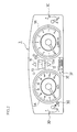
- FIG 2 is a front view showing an enlarged view of a combination meter in an embodiment of the present invention.
- FIG 3 shows the overall configuration of a control apparatus in an embodiment of the present invention.
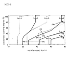
- FIG 4 shows a gearshift map in an embodiment of the present invention.
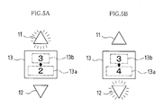
- FIG 5A shows an illumination state of an upshift lamp, and a display state of a display when an upshift is performed, in an embodiment of the present invention. FIG 5B shows an illumination state of a downshift lamp, and a display state of a display when an downshift is performed, in an embodiment of the present invention.
- FIG 6 is a flowchart that shows an operating procedure for gearshift indication control in an embodiment of the present invention.
- FIG 7 is a timing chart for comparing conventional gearshift indication control with gearshift indication control in an embodiment of the present invention.
-
- 1
- engine (internal combustion engine)
- 2
- manual transmission
- 4
- control apparatus
- Hereinafter, embodiments of the present invention will be described, by way of example, with reference to the accompanying drawings. The present embodiment illustrates a case in which the present invention is applied in an automobile provided with a manual transmission.
- FIG 1 is a side view of an automobile that shows the arrangement layout of an engine (internal combustion engine) 1, a
manual transmission 2, acombination meter 3, and acontrol apparatus 4, with the vehicle body indicated by imaginary lines. - The
manual transmission 2, for example, includes five gears, and has ashift knob 2a for manually performing a gearshift operation disposed protruding inside the vehicle cabin. - The
combination meter 3 is installed in a dashboard to the front of a driver seat inside the vehicle cabin, and as shown for example in FIG 2, is provided with aspeedometer 3A, atachometer 3B, a water temperature gauge 3C, afuel gauge 3D, an odometer 3E, atrip meter 3F, and the like, and various warning indicator lamps (not shown) and the like. - In the present embodiment, a gearshift indication apparatus is provided that indicates an appropriate gear position selection of the
manual transmission 2 for achieving improved fuel efficiency according to the running state of the automobile. Following is a description of this gearshift indication apparatus. - First, the
combination meter 3 is provided with, as display portions for gearshift indication, anupshift lamp 11 that illuminates when the gear position of themanual transmission 2 needs to be shifted up and adownshift lamp 12 that illuminates when the gear position needs to be shifted down, and adisplay 13 where various information in the form of numerals, characters, or the like is displayed. A display with a liquid crystal or seven-segment configuration is used as thedisplay 13. - Each of the
above lamps lamps lamps - Also, the
display 13 is, for example, provided with a present gearposition display portion 13a, and a target gearposition display portion 13b. The present gearposition display portion 13a displays the present gear position of themanual transmission 2 with a numeral or symbol, and the target gearposition display portion 13b displays the gear position to which a gearshift is indicated (gear position to which the driver should shift; hereinafter referred to as the target gear position) with a numeral or symbol. For example, the present gear position display in the present gearposition display portion 13a is displayed without blinking, and the target gear position display in the target gearposition display portion 13b is displayed in a blinking manner. - The
control apparatus 4 is ordinarily configured from a commonly known ECU (Electronic Control Unit), and for example, as shown in FIG 3, is provided with a CPU (Central Processing Unit) 42, a ROM (Read Only Memory) 43, a RAM (Random Access Memory) 44, abackup RAM 45, aninterface 46, and the like which are connected to each another by abidirectional bus 41. - The
CPU 42 perceives the running state of the vehicle based on output signals from various sensors (for example, avehicle speed sensor 21, anengine revolution sensor 22, agear position sensor 23, an acceleratoropening degree sensor 24, or the like) that are input via theinterface 46, and performs appropriate control as necessary. - Also, various programs, including at least a program for executing gearshift indication control that indicates an appropriate gear position selection of the
manual transmission 2 for achieving improved fuel efficiency according to the running state of the automobile, or the like, are stored in theROM 43, in addition to various programs for executing control related to basic driving of the automobile. The specific content of this gearshift indication control will be described below. - The
RAM 44 is a memory in which results of computation by theCPU 42, data input from the various sensors, and the like, are temporarily stored, and thebackup RAM 45 is a nonvolatile memory in which various data to be saved is stored. - Also, a gearshift map (FIG 4) is stored in the
ROM 43. The gearshift map is a control map used for the above gearshift indication control, and has gearshift lines (gear switch lines) for obtaining an optimum gear for the vehicle speed and the accelerator opening degree. More specifically, an optimum gear suitable for the running state of the automobile is obtained according to this gearshift map, and when the obtained gear (target gear position) is different from the gear that the driver has set (present gear position), a gear indication operation is performed by theabove lamps position display portion 13b of thedisplay 13. - Following is a description of the above gearshift map. As shown by way of example in FIG. 4, a plurality of gearshift lines are plotted. In FIG 4, solid lines indicate gearshift lines used in an upshift operation that increases the gear, and broken lines indicate gearshift lines used in a downshift operation that decreases the gear. Also, the respective switching directions of upshifts and downshifts are indicated in FIG 4 using numerals and arrows.
- As is clear from FIG 4, with the gearshift lines used in an upshift operation, in a circumstance in which the accelerator is open to a small degree, the gear is increased even when the vehicle speed is comparatively low. For example, the shift lines are set such that in a case in which an accelerator opening degree of 20% is maintained from the time that the automobile begins moving, when the vehicle speed becomes about 20 km/h, a switch from first gear to second gear is demanded, and afterward, when the vehicle speed becomes about 30 km/h, a switch from second gear to third gear is demanded, and when the vehicle speed becomes about 45 km/h, a switch from third gear to fourth gear is demanded. When the accelerator is open to a small degree, it is possible to determine that the driver is not demanding fast acceleration, and so the gear is increased in the above manner in order to achieve an improvement in fuel efficiency by using a high gear. Therefore, in a region of the gearshift map in which the accelerator is open to a small degree, there is a small gap between each of the gearshift lines (the gearshift lines are closely spaced).
- On the other hand, when the accelerator is open to a large degree, the gear is not switched until the vehicle speed becomes comparatively high. For example, the shift lines are set such that in a case in which an accelerator opening degree of 80% is maintained from the time that the automobile begins moving, a switch from first gear to second gear is not demanded until the vehicle speed becomes about 38 km/h, and a switch from second gear to third gear is not demanded until the vehicle speed becomes about 75 km/h. When the accelerator is open to a large degree, it is possible to determine that the driver is demanding fast acceleration, and so the demand for fast acceleration is met by maintaining a low gear. Therefore, in a region of the gearshift map in which the accelerator is open to a large degree, there is a large gap between each of the gearshift lines (the gearshift lines are widely spaced).
- Likewise, also with respect to the gearshift lines used in a downshift operation, in a region of the gearshift map in which the accelerator is open to a small degree, there is a small gap between each of the gearshift lines (the gearshift lines are closely spaced), and in a region of the gearshift map in which the accelerator is open to a large degree, there is a large gap between each of the gearshift lines (the gearshift lines are widely spaced).
- In this manner, the gearshift indication apparatus is configured from the
above upshift lamp 11 and downshiftlamp 12 that serve as display portions for gearshift indication, thedisplay 13, and thecontrol apparatus 4. - Following is a description of the basic operation of the gearshift indication by the gearshift indication apparatus configured in the manner described above.
- The
control apparatus 4 identifies the present gear position of themanual transmission 2 based on a detection signal from thegear position sensor 23, and displays the gear position in the form of a numeral in the present gearposition display portion 13a of thedisplay 13. - As gearshift indication control by the
control apparatus 4, the running state of the automobile is perceived based on signals output from thevehicle speed sensor 21 and the acceleratoropening degree sensor 24, a gear (optimum gear) for running in a manner that is desirable for achieving an improvement in fuel efficiency or the like is read out from the above gear map (FIG 4), and a judgment is performed of whether or not a gearshift operation is necessary. - When it is desirable to maintain a state in which gearshifting is not necessary (when the gear is appropriately set), the
upshift lamp 11 and thedownshift lamp 12 are both turned off, and the target gearposition display portion 13b is placed in a non-displaying state. - When it is desirable to change gears and an upshift is demanded, as shown in FIG 5A, the
upshift lamp 11 is illuminated, and the target gear position is displayed in the target gearposition display portion 13b. FIG 5A shows a state in which the present gear position is second gear, and the target gear position is third gear. For example, FIG 5A shows the display state when, in a state in which the automobile is running with the present gear position of themanual transmission 2 set to second gear, the driving state has changed from point PA to point PB in FIG 4. - On the other hand, when it is desirable to change gears and a downshift is demanded, as shown in FIG 5B, the
downshift lamp 12 is illuminated, and the target gear position is displayed in the target gearposition display portion 13b. FIG 5B shows a state in which the present gear position is fourth gear, and the target gear position is third gear. For example, FIG 5B shows the display state when, in a state in which the automobile is running with the present gear position of themanual transmission 2 set to fourth gear, the driving state has changed from point PC to point PD in FIG 4. - When the driver performs a gearshift operation to shift to the appropriate gear according to this indication, the above indication (illumination of the
lamps lamps - In the gearshift indication apparatus according to the present embodiment, gearshift indication delay control (a delay operation by a gearshift indication delaying means) is performed that provides a predetermined interval of time between establishment of a condition for execution of gearshift indication (when the running state of the automobile crosses a gearshift line on the gearshift map) and actual execution of a gearshift indication to the driver. That is, a delay timer is provided that starts a count after it has been judged that a gearshift operation is necessary in order to obtain an optimum gear according to the gearshift map, and an actual gearshift indication (illumination of lamps and display of the target gear position) is executed after a time period counted by the delay timer has elapsed. With this configuration, it is possible to avoid a circumstance in which the driver performs a gearshift operation and then immediately afterward a subsequent gearshift indication is displayed, and thus the driver is not bothered.
- More specifically, the gearshift indication apparatus in the present embodiment is provided with two types of timers: a lamp off timer and a gearshift indication permission timer. Following is a description of these timers.
- The above lamp off timer is a delay timer that starts a count at the point in time that the
above lamps position display portion 13b are turned off (the point in time when display is released according to gearshift operation by the driver). Illumination of theabove lamps position display portion 13b are not performed before the time counted by the lamp off timer elapses, even if a gearshift indication condition has been established (even if due to the running state of the automobile crossing a gearshift line on the gearshift map, a state occurred in which the optimum gear obtained from the gearshift map is different than the gear actually selected by the driver). Thus, it is possible to avoid bothering the driver by frequently performing the gearshift indication operation. In the present embodiment, a timer value of the lamp off timer (time from when the count starts to when time counted by the lamp off timer elapses) is always a fixed value (for example, 1 second). - On the other hand, the gearshift indication permission timer is a delay timer that starts a count at the point in time that the above gearshift indication condition is established and the time counted by the above lamp off timer has elapsed (the point of time that an AND condition of these has been established). Due to elapsing of the time counted by the gearshift indication permission timer, a gearshift indication operation (illumination of the
above lamps position display portion 13b) according to the gearshift indication condition are permitted. - The present embodiment is characterized in that a timer value of the gearshift indication permission timer (time from when the count starts to when time counted by the gearshift indication permission timer elapses) is changed according to the accelerator opening degree (delay time change operation by a delay time changing means).
- Specifically, for a larger accelerator opening degree, the count value of the gearshift indication permission timer is set to a shorter value, and so the time from establishment of a gearshift indication execution condition to the time of actually executing the gearshift indication to the driver is set to a shorter value. For example, when the accelerator opening degree is less than 20%, the count value (the delay time) of the gearshift indication permission timer is set to 2 seconds, when the accelerator opening degree is 20% or more and less than 80%, the count value (the delay time) of the gearshift indication permission timer is set to 1.5 seconds, and when the accelerator opening degree is 80% or more the count value (the delay time) of the gearshift indication permission timer is set to 1 second.
- Following is a description of the operation procedure of gearshift indication control (gearshift indication control for an upshift) in the present embodiment, with reference to the flowchart shown in FIG 6. This routine shown in FIG 6 is, for example executed at each of a predetermined time after the engine starts, for example, every several milliseconds. Also, this routine may be executed at each instance of a predetermined crank angle.
- First, in Step ST1, a determination is made of whether or not the running state of the automobile has crossed over an upshift gearshift line (the gearshift lines indicated by solid lines in the gearshift map in FIG 4) to the upshift side of the upshift gear line. When determined NO in Step ST1, the present running state of the automobile is deemed to be a state in which the present gear position is optimum (an appropriate gear is set), and in Step ST2, both of the
lamps position display portion 13b. Then the present routine ends. - On the other hand, when determined YES in above Step ST1, in Step ST3, a determination is made of whether or not a time Toff since turning off the
above lamps position display portion 13b in the previous instance has exceeded a minimum lamp off time Ts. The time Toff is a time counted by the lamp off timer as described above, and corresponds to a delay time from when theabove lamps position display portion 13b are turned off by a gearshift operation according to a prior gearshift indication to when it is possible to perform the next gearshift indication. Thus, it is possible to avoid a state in which a gearshift indication is frequently produced during a short period of time. That is, illumination of theabove lamps position display portion 13b are not performed before the time counted by the lamp off timer elapses, even if a gearshift indication condition has been established (even if the running state of the automobile crossed over a gearshift line). - When determined NO in above Step ST3, a predetermined value (α) is added to the present count time (Toff), and the routine returns to Step ST1, using this as a new count time (Toff). The predetermined value (α) is a sum of the amount of time needed for detection of the present count time (Toff) and the amount of time needed for making the determination in above Step ST3.
- When, in the determination of Step ST1, a state is being maintained in which the running state of the automobile has crossed over an upshift gearshift line, after completion of Step S4, the operations of Steps ST1, ST3, and ST4 are repeated, waiting for a YES determination in Step S3.
- Because the lamp off timer as described above starts a count at the point in time that the
above lamps position display portion 13b are turned off, it is possible that the time counted by the lamp off timer has already elapsed at the point in time that a gearshift indication condition is established (the point in time that a YES determination is made in Step ST1). In this case, after a YES determination has been made in Step ST1, the routine moves directly to the operations from Step ST5 onward. - On the other hand, when the running state of the automobile has crossed over an upshift gearshift line in the opposite direction (to the downshift side) and the gear upshift demand has been released before the time counted by the lamp off timer elapses (before a YES determination is made in Step ST3), the routine moves from Step ST1 to Step ST2.
- When the time counted by the lamp off timer has elapsed with a state maintained in which the running state of the automobile has crossed over an upshift gearshift line to the upshift side, and a YES determination has been made in Step ST3, the routine moves to Step ST5, and the accelerator opening degree is detected based on a detection signal from the accelerator opening degree sensor 24 (an engine load detection operation by an engine load detection means). Then, a determination is made of whether or not that accelerator opening degree is less than a predetermined detection value Sa (for example, 20%). When this determination is YES, the routine moves to Step ST6, a determination is made that the accelerator opening degree is low, and the count value (Ton) of the above gearshift indication permission timer is set to a time Ta (for example, 2 seconds)(a time that is longer than times Tb and Tc described below). That is, a long time is set for the count value (Ton) of the above gearshift indication permission timer, which sets the time from when the gearshift indication condition is established and the time counted by the above lamp off timer has elapsed, to when actual execution of a gearshift indication to the driver is permitted.
- On the other hand, when a NO determination has been made in Step ST5, the routine moves to Step ST7, and a determination is made of whether or not the accelerator opening degree is equal to or greater than the predetermined detection value Sa (for example, 20%), and less than a predetermined value Sb (for example, 80%). When this determination is YES, the routine moves to Step ST8, a determination is made that the accelerator opening degree is moderate, and the count value (Ton) of the above gearshift indication permission timer is set to a time Tb that is slightly shorter than the above Ta (for example, 1.5 seconds; a time that is slightly longer than time Tc described below). That is, a shorter time is set for the count value (Ton) of the above gearshift indication permission timer, which sets the time from when the gearshift indication condition is established and the time counted by the above lamp off timer has elapsed, to when actual execution of a gearshift indication to the driver is permitted, than in the above case in which the accelerator opening degree is low.
- When a NO determination has been made in Step ST7, a determination is made that the accelerator opening degree is equal to or greater than the predetermined detection value Sb (for example, 80%), and so the accelerator opening degree is high, and therefore the count value (Ton) of the above gearshift indication permission timer is set to a time that is still shorter than the above Tb (for example, 1 second). That is, a still shorter time Tc is set for the count value (Ton) of the above gearshift indication permission timer, which sets the time from when the gearshift indication condition is established and the time counted by the above lamp off timer has elapsed, to when actual execution of a gearshift indication to the driver is permitted, than in the cases above.
- After the count value (Ton) of the gearshift indication permission timer has been set according to the accelerator opening degree in the above manner, the count of the gearshift indication permission timer is started, and in Step ST10, a determination is made of whether or not the time counted by the gearshift indication permission timer has elapsed. In this case, the time until the time counted by the gearshift indication permission timer has elapsed is shorter for a higher accelerator opening degree, a YES determination is made in Step ST10, and a gearshift indication operation of Step ST11 is executed early. More specifically, illumination of the
upshift lamp 11 and display of the target gear position with the target gearposition display portion 13b of thedisplay 13 based on the gearshift map are performed early. - In this manner, a gearshift indication to the driver is performed, and when a gearshift operation according to that gearshift indication is performed, the
upshift lamp 11 is turned off, and the targetgear position portion 13b is placed in a non-displaying state. By performing an operation as described above, a running state of the automobile is obtained in which an appropriate gear has been set. - As described above, in the present embodiment, because the delay time from when a gearshift indication condition is established to when a gearshift indication is executed is set shorter for a higher accelerator opening degree, it is possible to perform a gearshift indication to the driver before the number of engine revolutions rises too much. Therefore, without changing the gearshift lines of the gearshift map (without performing a design change from conventional gearshift lines), it is possible to avoid worsening fuel efficiency and adversely affecting engine longevity, which result from an excessive increase in the number of engine revolutions.
- FIG 7 is a timing chart that shows changes in the accelerator opening degree, vehicle speed, present gear (shift position set by driver operation), gearshift line demanded gear (gear demanded according to the gearshift map; the optimum gear), upshift lamp illumination state, lamp off timer, gearshift indication permission timer, and number of engine revolutions. The broken lines show states of change according to the conventional technology, and the solid lines show states of change according to the present embodiment.
- In FIG. 7, after establishment of a gearshift indication condition (time I in FIG 7), with the conventional technology the time counted by the gearshift indication permission timer elapses after delaying for a delay time E, and at time II in FIG 7, gearshift indication is performed by illumination of the
upshift lamp 11 or the like. On the other hand, according to the present embodiment, after establishment of a gearshift indication condition (time I), the time counted by the gearshift indication permission timer elapses after delaying for a delay time F (<time E), and at time III in FIG 7, gearshift indication is performed by illumination of theupshift lamp 11 or the like. The same is true also at other times of establishment of a gearshift indication condition; according to the present embodiment, gearshift indication is performed earlier than with the conventional technology. - In this manner, according to the conventional technology (broken lines), in a circumstance in which the accelerator opening degree is high, a delay in the upshift indication (with the conventional technology, the upshift indications are delayed by t1, t2, and t3 respectively for each of the upshift timings in FIG 7) results in the number of engine revolutions becoming more than necessary (refer to the number of engine revolutions indicated by broken lines in FIG 7), and so in this circumstance there is a risk of worsening fuel efficiency and adversely affecting engine longevity.
- On the other hand, according to the present embodiment, in a circumstance in which the accelerator opening degree is high, because the upshift indication is performed quickly (upshift indications are performed at earlier times than with the above conventional delays by t1, t2, and t3, and thus the gearshift operation of the driver also is performed s1, s2, and s3 earlier than with the conventional technology), the number of engine revolutions does not rise too much (refer to the number of engine revolutions indicated by solid lines in FIG 7), and therefore, an improvement in fuel efficiency is achieved, and the above adverse effect on engine longevity is eliminated.
- In the above embodiment, the operation procedure of gearshift indication control for an upshift was described as gearshift indication control, but likewise in the case of a downshift, a configuration may be adopted in which the count value (Ton) of the gearshift indication permission timer is changed according to the accelerator opening degree.
- In this case as well, as in the case of the above embodiment, for a larger accelerator opening degree, the count value of the gearshift indication permission timer is set to a shorter value, and so the time from establishment of a gearshift indication execution condition to the time of actually executing the gearshift indication (downshift indication) to the driver is set to a shorter value.
- With this sort of operation procedure of gearshift indication control for a downshift, when the driver quickly increases the accelerator opening degree to demand fast acceleration, so that a downshift has become necessary, it is possible to perform a downshift indication within a short period of time, and so the driver can quickly set a gear that is suitable for quick acceleration by performing a gearshift operation according to the downshift indication.
- On the other hand, in a circumstance in which vehicle speed drops while the accelerator opening degree remains small, the gear is downshifted according to the gearshift map, but in this case the count value (Ton) of the gearshift indication permission timer is set to a large value. That is, gearshift indication is performed with a long delay time. Thus, it is conceivable that the driving state of the automobile will cross over two gearshift lines to the downshift side during the delay time (such as a case in which the driving state changes from point PG to point PH in FIG 4), and so it is also possible that after the delay time ends, a display is executed in the target gear
position display portion 13b that prompts the driver to perform a gearshift operation to a gear that is two gears lower than the present gear. That is, when the driver performs a downshift operation according to the gearshift indication apparatus, it is possible to not perform a bothersome operation of decreasing gears one by one, and instead decrease by two gears at once; as a result operability of the downshifting operation is good. - In the above embodiments, the count value (Ton) of the gearshift indication permission timer was changed according to the accelerator opening degree. In Modified Example 2, instead, a configuration may be adopted in which a larger count value (Ton) of the gearshift indication permission timer is set for a higher degree of vehicle acceleration detected by an acceleration sensor (G sensor) installed to the vehicle body.
- The accelerator opening degree is correlated with the degree of automobile acceleration. When the accelerator opening degree is large, an increase in the amount of air intake into a combustion chamber of the engine results in increased engine output, and thus the degree of automobile acceleration is increased; therefore the accelerator opening degree can be estimated from the value detected by the acceleration sensor.
- The above embodiments and modified examples illustrated a case in which the present invention is applied in an automobile provided with the
manual transmission 2. The present invention is not limited to such a configuration; for example, the present invention is applicable also in an automobile provided with an automatic transmission having a manual gearshift function. Automatic transmissions having a manual gearshift function have become widespread, and an example of such a transmission is a so-called sequential shift transmission in which upshifts and downshifts are performed by an operation of pushing forward and an operation of pushing backward. - Also, in the above embodiments and modified examples, a case was illustrated in which the
lamps display 13 are installed in thecombination meter 3 as display portions for gearshift indication, but their installation positions are not particularly limited. For example, thelamps display 13 can be installed not in thecombination meter 3, but in the vicinity of thecombination meter 3, and in addition, thelamps display 13 can perform display using a commonly known navigation system, or using a heads-up display system that projects information onto a windshield. - Also, the count value of the gearshift indication permission timer (in the above embodiments, 2 sec., 1.5 sec., 1 sec.) and the value of the accelerator opening degree for determining the count value (in the above embodiments, 20%, 80%) are not limited to the values stated above, and can be set as desired. Also, the gearshift lines of the gearshift map are not limited to those shown in FIG 4, and can be set as desired.
- Also, in the above embodiments and modified examples, a configuration was adopted in which a smaller value was set for the count value of the gearshift indication permission timer (a shorter delay time was set) in the case of a greater engine load such as the accelerator opening degree, but the technical idea of the present invention also encompasses, according to the circumstances, setting a larger value for the count value of the gearshift indication permission timer in the case of a greater engine load (setting a longer delay time). For example, in a circumstance in which the accelerator opening degree is high, there is a possibility that a driving operation (accelerator work) will be performed such that the accelerator opening degree changes greatly, and in this case, for a larger accelerator opening degree, when the count value of the gearshift indication permission timer is set to a larger value, even if the change in the accelerator opening degree is great, a hunting phenomenon in which downshift indication is repeatedly performed from moment to moment is eliminated. This sort of setting of the count value of the gearshift indication permission timer (for a larger engine load, setting of a smaller value for the count value of the gearshift indication permission timer, or conversely, setting of a larger value for the count value of the gearshift indication permission timer) is appropriately selected according to a form of indication by the gearshift indication apparatus preferred by the driver, the running performance demanded by the automobile, or the like.
- The present invention may be embodied in various other forms without departing from the spirit or essential characteristics thereof. The embodiments disclosed in this application are to be considered in all respects as illustrative and not limiting. The scope of the invention is indicated by the appended claims rather than by the foregoing description, and all modifications or changes that come within the meaning and range of equivalency of the claims are intended to be embraced therein.
- This application claims priority based on
Japanese Patent Application No. 2006-279844
Claims (5)
- An automobile gearshift indication apparatus that is used in an automobile equipped with a transmission capable of manual operation, and when a gearshift indication condition has been established in which an optimum gear of the transmission desired according to a driving state of the automobile is different from a gear selected by a driver, performs a gearshift indication to the driver so as to prompt the driver to shift to the optimum gear, the automobile gearshift indication apparatus comprising:an engine load detection means that detects an engine load;a gearshift indication delaying means that, after the gearshift indication condition has been established, delays the gearshift indication to the driver for a predetermined time; anda delay time changing means that receives an output of the engine load detection means, and changes the delay time by the gearshift indication delaying means according to the size of the engine load.
- The automobile gearshift indication apparatus according to claim 1, wherein the delay time changing means sets the delay time by the gearshift indication delaying means to a shorter time for a larger engine load.
- The automobile gearshift indication apparatus according to claim 1 or 2, comprising:a lamp off timer that starts a count when the driver has performed a gearshift operation according to the gearshift indication and thus the gearshift indication has been released; anda gearshift indication permission timer that starts a count with establishment of a gearshift indication condition and elapsing of time counted by the lamp off timer as an AND condition, wherein gearshift indication to the driver is performed when the time counted by the gearshift indication permission timer has elapsed,wherein the delay time changing means sets a time from when the gearshift indication permission timer starts the count to when the time counted by the gearshift indication permission timer elapses to a shorter time for a larger engine load.
- The automobile gearshift indication apparatus according to any one of claims 1 to 3,
wherein the engine load detection means obtains the engine load from an accelerator opening degree of the automobile. - The automobile gearshift indication apparatus according to any one of claims 1 to 3,
wherein the engine load detection means obtains the engine load from the degree of automobile acceleration.
Applications Claiming Priority (1)
| Application Number | Priority Date | Filing Date | Title |
|---|---|---|---|
| JP2006279844A JP4274224B2 (en) | 2006-10-13 | 2006-10-13 | Automobile shift instruction device |
Publications (3)
| Publication Number | Publication Date |
|---|---|
| EP1911997A2 true EP1911997A2 (en) | 2008-04-16 |
| EP1911997A3 EP1911997A3 (en) | 2012-01-25 |
| EP1911997B1 EP1911997B1 (en) | 2013-11-20 |
Family
ID=38860389
Family Applications (1)
| Application Number | Title | Priority Date | Filing Date |
|---|---|---|---|
| EP07254015.6A Not-in-force EP1911997B1 (en) | 2006-10-13 | 2007-10-10 | Automobile gearshift indication apparatus |
Country Status (2)
| Country | Link |
|---|---|
| EP (1) | EP1911997B1 (en) |
| JP (1) | JP4274224B2 (en) |
Cited By (3)
| Publication number | Priority date | Publication date | Assignee | Title |
|---|---|---|---|---|
| EP2028397A3 (en) * | 2007-08-24 | 2012-02-08 | Audi AG | Motor vehicle with a display of the switching time in connection with information about the engine torque delivered |
| EP2602146A4 (en) * | 2011-04-01 | 2014-09-03 | Toyota Motor Co Ltd | REPORT PASSING INSTRUCTION DEVICE |
| WO2018162299A1 (en) * | 2017-03-08 | 2018-09-13 | Bayerische Motoren Werke Aktiengesellschaft | Control device in a motor vehicle for outputting a gear-shift recommendation |
Families Citing this family (4)
| Publication number | Priority date | Publication date | Assignee | Title |
|---|---|---|---|---|
| CN102869528B (en) * | 2010-04-28 | 2015-09-23 | 丰田自动车株式会社 | The Gear shift instruction system of vehicle |
| JP5751193B2 (en) * | 2012-02-24 | 2015-07-22 | トヨタ自動車株式会社 | Speed change instruction device |
| JP6094729B2 (en) * | 2012-10-18 | 2017-03-15 | 三菱自動車工業株式会社 | Vehicle display device |
| JP5979760B2 (en) * | 2013-02-12 | 2016-08-31 | 富士重工業株式会社 | Shifting operation instruction device |
Citations (3)
| Publication number | Priority date | Publication date | Assignee | Title |
|---|---|---|---|---|
| JPS5962752A (en) | 1982-09-30 | 1984-04-10 | Nissan Motor Co Ltd | Shift indicator for car equipped with manually operated speed change gear |
| JPS6393631A (en) | 1986-10-07 | 1988-04-23 | Mazda Motor Corp | Speed change timing instruction device for automobile |
| JP2006279844A (en) | 2005-03-30 | 2006-10-12 | Matsushita Electric Ind Co Ltd | Portable terminal device, charger, and charging system |
Family Cites Families (2)
| Publication number | Priority date | Publication date | Assignee | Title |
|---|---|---|---|---|
| JPS6118533A (en) * | 1984-07-04 | 1986-01-27 | Mazda Motor Corp | Speed-change timing indicator for car |
| JPS6229425A (en) * | 1985-07-30 | 1987-02-07 | Mazda Motor Corp | Gear shift timing indicating device for car |
-
2006
- 2006-10-13 JP JP2006279844A patent/JP4274224B2/en not_active Expired - Fee Related
-
2007
- 2007-10-10 EP EP07254015.6A patent/EP1911997B1/en not_active Not-in-force
Patent Citations (3)
| Publication number | Priority date | Publication date | Assignee | Title |
|---|---|---|---|---|
| JPS5962752A (en) | 1982-09-30 | 1984-04-10 | Nissan Motor Co Ltd | Shift indicator for car equipped with manually operated speed change gear |
| JPS6393631A (en) | 1986-10-07 | 1988-04-23 | Mazda Motor Corp | Speed change timing instruction device for automobile |
| JP2006279844A (en) | 2005-03-30 | 2006-10-12 | Matsushita Electric Ind Co Ltd | Portable terminal device, charger, and charging system |
Cited By (5)
| Publication number | Priority date | Publication date | Assignee | Title |
|---|---|---|---|---|
| EP2028397A3 (en) * | 2007-08-24 | 2012-02-08 | Audi AG | Motor vehicle with a display of the switching time in connection with information about the engine torque delivered |
| EP2602146A4 (en) * | 2011-04-01 | 2014-09-03 | Toyota Motor Co Ltd | REPORT PASSING INSTRUCTION DEVICE |
| WO2018162299A1 (en) * | 2017-03-08 | 2018-09-13 | Bayerische Motoren Werke Aktiengesellschaft | Control device in a motor vehicle for outputting a gear-shift recommendation |
| CN110177966A (en) * | 2017-03-08 | 2019-08-27 | 宝马股份公司 | The control device recommended for exporting shift in motor vehicle |
| CN110177966B (en) * | 2017-03-08 | 2021-09-10 | 宝马股份公司 | Control device for outputting a gear change recommendation in a motor vehicle |
Also Published As
| Publication number | Publication date |
|---|---|
| JP4274224B2 (en) | 2009-06-03 |
| JP2008095881A (en) | 2008-04-24 |
| EP1911997A3 (en) | 2012-01-25 |
| EP1911997B1 (en) | 2013-11-20 |
Similar Documents
| Publication | Publication Date | Title |
|---|---|---|
| EP1930631B1 (en) | Gear position determination apparatus for manual transmission, gear-shift prompting apparatus for vehicle and method therefore | |
| EP1911997B1 (en) | Automobile gearshift indication apparatus | |
| EP2090808B1 (en) | Gear shift indicator and gear shift indicating method | |
| US6363805B1 (en) | System and process for controlling an automatically shifting transmission | |
| EP0937918A2 (en) | Range selector failure detecting system and method for automatic transmission | |
| US20120078477A1 (en) | Vehicle control device and vehicle control method | |
| US20100137103A1 (en) | Shift control device and shift control method for automatic transmission | |
| EP1944529B1 (en) | Gear determination apparatus, gear determination method, gear-shift instruction apparatus and gear-shift instruction method | |
| JP2003220851A (en) | Operating status display device for vehicles with automatic transmission | |
| EP1826461B1 (en) | Gear shift instruction device and gear shift instruction method | |
| WO2011108224A1 (en) | Gear shift indicator | |
| EP1921353A2 (en) | Gear shift instruction device and gear shift instruction method | |
| US7704187B2 (en) | Shift control apparatus for automatic transmission | |
| US10174839B2 (en) | Method for reducing the amount of fuel used by an engine of a motor vehicle | |
| EP0984209A1 (en) | Method/system for controlling upshifting in an automated mechanical transmission system | |
| JP4687164B2 (en) | Transmission control device | |
| US6827667B2 (en) | Select-shock control system and method for automotive automatic transmission | |
| EP1887262B1 (en) | Shift instructing apparatus and shift instructing method | |
| JP4253013B2 (en) | Driving state display device for vehicles with automatic transmission | |
| JP2016210376A (en) | Vehicle shift instruction device | |
| US5048650A (en) | Engine brake running control for automatic transmission in automatic drive range | |
| JP5696570B2 (en) | Shift instruction control device | |
| US20040248697A1 (en) | Method for triggering an upshift during kick-down conditions | |
| JP4893280B2 (en) | Notification device for vehicles with automatic transmission | |
| JP2011220227A (en) | Fuel saving drive guiding device |
Legal Events
| Date | Code | Title | Description |
|---|---|---|---|
| PUAI | Public reference made under article 153(3) epc to a published international application that has entered the european phase |
Free format text: ORIGINAL CODE: 0009012 |
|
| AK | Designated contracting states |
Kind code of ref document: A2 Designated state(s): AT BE BG CH CY CZ DE DK EE ES FI FR GB GR HU IE IS IT LI LT LU LV MC MT NL PL PT RO SE SI SK TR |
|
| AX | Request for extension of the european patent |
Extension state: AL BA HR MK RS |
|
| 17P | Request for examination filed |
Effective date: 20080801 |
|
| PUAL | Search report despatched |
Free format text: ORIGINAL CODE: 0009013 |
|
| AK | Designated contracting states |
Kind code of ref document: A3 Designated state(s): AT BE BG CH CY CZ DE DK EE ES FI FR GB GR HU IE IS IT LI LT LU LV MC MT NL PL PT RO SE SI SK TR |
|
| AX | Request for extension of the european patent |
Extension state: AL BA HR MK RS |
|
| RIC1 | Information provided on ipc code assigned before grant |
Ipc: F16H 63/42 20060101AFI20111216BHEP |
|
| AKX | Designation fees paid |
Designated state(s): DE FR GB IT |
|
| RAP1 | Party data changed (applicant data changed or rights of an application transferred) |
Owner name: TOYOTA JIDOSHA KABUSHIKI KAISHA |
|
| GRAP | Despatch of communication of intention to grant a patent |
Free format text: ORIGINAL CODE: EPIDOSNIGR1 |
|
| INTG | Intention to grant announced |
Effective date: 20130524 |
|
| GRAS | Grant fee paid |
Free format text: ORIGINAL CODE: EPIDOSNIGR3 |
|
| GRAA | (expected) grant |
Free format text: ORIGINAL CODE: 0009210 |
|
| AK | Designated contracting states |
Kind code of ref document: B1 Designated state(s): DE FR GB IT |
|
| REG | Reference to a national code |
Ref country code: GB Ref legal event code: FG4D |
|
| REG | Reference to a national code |
Ref country code: DE Ref legal event code: R096 Ref document number: 602007033864 Country of ref document: DE Effective date: 20140116 |
|
| REG | Reference to a national code |
Ref country code: DE Ref legal event code: R084 Ref document number: 602007033864 Country of ref document: DE Effective date: 20140304 |
|
| REG | Reference to a national code |
Ref country code: DE Ref legal event code: R097 Ref document number: 602007033864 Country of ref document: DE |
|
| PLBE | No opposition filed within time limit |
Free format text: ORIGINAL CODE: 0009261 |
|
| STAA | Information on the status of an ep patent application or granted ep patent |
Free format text: STATUS: NO OPPOSITION FILED WITHIN TIME LIMIT |
|
| 26N | No opposition filed |
Effective date: 20140821 |
|
| REG | Reference to a national code |
Ref country code: DE Ref legal event code: R097 Ref document number: 602007033864 Country of ref document: DE Effective date: 20140821 |
|
| GBPC | Gb: european patent ceased through non-payment of renewal fee |
Effective date: 20141010 |
|
| PG25 | Lapsed in a contracting state [announced via postgrant information from national office to epo] |
Ref country code: GB Free format text: LAPSE BECAUSE OF NON-PAYMENT OF DUE FEES Effective date: 20141010 |
|
| REG | Reference to a national code |
Ref country code: FR Ref legal event code: ST Effective date: 20150630 |
|
| PG25 | Lapsed in a contracting state [announced via postgrant information from national office to epo] |
Ref country code: IT Free format text: LAPSE BECAUSE OF FAILURE TO SUBMIT A TRANSLATION OF THE DESCRIPTION OR TO PAY THE FEE WITHIN THE PRESCRIBED TIME-LIMIT Effective date: 20131120 Ref country code: FR Free format text: LAPSE BECAUSE OF NON-PAYMENT OF DUE FEES Effective date: 20141031 |
|
| PGFP | Annual fee paid to national office [announced via postgrant information from national office to epo] |
Ref country code: DE Payment date: 20180925 Year of fee payment: 12 |
|
| REG | Reference to a national code |
Ref country code: DE Ref legal event code: R119 Ref document number: 602007033864 Country of ref document: DE |
|
| PG25 | Lapsed in a contracting state [announced via postgrant information from national office to epo] |
Ref country code: DE Free format text: LAPSE BECAUSE OF NON-PAYMENT OF DUE FEES Effective date: 20200501 |