EP1911706B1 - Bahnenschneider mit Bahnenschneideschlaufen - Google Patents
Bahnenschneider mit Bahnenschneideschlaufen Download PDFInfo
- Publication number
- EP1911706B1 EP1911706B1 EP07019924.5A EP07019924A EP1911706B1 EP 1911706 B1 EP1911706 B1 EP 1911706B1 EP 07019924 A EP07019924 A EP 07019924A EP 1911706 B1 EP1911706 B1 EP 1911706B1
- Authority
- EP
- European Patent Office
- Prior art keywords
- web
- velocity
- loop size
- loop
- cutter
- Prior art date
- Legal status (The legal status is an assumption and is not a legal conclusion. Google has not performed a legal analysis and makes no representation as to the accuracy of the status listed.)
- Expired - Fee Related
Links
Images


Classifications
-
- B—PERFORMING OPERATIONS; TRANSPORTING
- B65—CONVEYING; PACKING; STORING; HANDLING THIN OR FILAMENTARY MATERIAL
- B65H—HANDLING THIN OR FILAMENTARY MATERIAL, e.g. SHEETS, WEBS, CABLES
- B65H23/00—Registering, tensioning, smoothing or guiding webs
- B65H23/04—Registering, tensioning, smoothing or guiding webs longitudinally
- B65H23/044—Sensing web tension
-
- B—PERFORMING OPERATIONS; TRANSPORTING
- B65—CONVEYING; PACKING; STORING; HANDLING THIN OR FILAMENTARY MATERIAL
- B65H—HANDLING THIN OR FILAMENTARY MATERIAL, e.g. SHEETS, WEBS, CABLES
- B65H23/00—Registering, tensioning, smoothing or guiding webs
- B65H23/04—Registering, tensioning, smoothing or guiding webs longitudinally
- B65H23/18—Registering, tensioning, smoothing or guiding webs longitudinally by controlling or regulating the web-advancing mechanism, e.g. mechanism acting on the running web
- B65H23/188—Registering, tensioning, smoothing or guiding webs longitudinally by controlling or regulating the web-advancing mechanism, e.g. mechanism acting on the running web in connection with running-web
- B65H23/192—Registering, tensioning, smoothing or guiding webs longitudinally by controlling or regulating the web-advancing mechanism, e.g. mechanism acting on the running web in connection with running-web motor-controlled
-
- B—PERFORMING OPERATIONS; TRANSPORTING
- B65—CONVEYING; PACKING; STORING; HANDLING THIN OR FILAMENTARY MATERIAL
- B65H—HANDLING THIN OR FILAMENTARY MATERIAL, e.g. SHEETS, WEBS, CABLES
- B65H2301/00—Handling processes for sheets or webs
- B65H2301/10—Selective handling processes
- B65H2301/12—Selective handling processes of sheets or web
- B65H2301/121—Selective handling processes of sheets or web for sheet handling processes, i.e. wherein the web is cut into sheets
-
- B—PERFORMING OPERATIONS; TRANSPORTING
- B65—CONVEYING; PACKING; STORING; HANDLING THIN OR FILAMENTARY MATERIAL
- B65H—HANDLING THIN OR FILAMENTARY MATERIAL, e.g. SHEETS, WEBS, CABLES
- B65H2701/00—Handled material; Storage means
- B65H2701/10—Handled articles or webs
- B65H2701/11—Dimensional aspect of article or web
- B65H2701/112—Section geometry
- B65H2701/1123—Folded article or web
- B65H2701/11231—Fan-folded material or zig-zag or leporello
Definitions
- the present invention relates generally to a web cutter and to a method for controlling a web and is applicable to a mail processing machine and, more particularly, to the input portion of a high speed inserter system in which individual sheets are cut from a continuous web of printed materials for use in mass-production of mail pieces.
- Inserter systems such as those applicable for use with the present invention, are mail processing machines typically used by organizations such as banks, insurance companies and utility companies for producing a large volume of specific mailings where the contents of each mail item are directed to a particular addressee.
- US-A-5,392,977 describes a coil material supply apparatus provided between an uncoiler for unwinding a coil material (or a leveler for flattening the unwound coil material) and an intermittent feed device of a mechanical press.
- This apparatus includes a pair of feed rollers for feeding the coil material upwardly, a servo motor for driving the feed rollers, position sensors for detecting the amount of a loop of the coil material, and a controller responsive to a detection signal from the position sensors for controlling the rotation of the servomotor to control the loop to an optimum amount.
- the typical inserter system resembles a manufacturing assembly line. Sheets and other raw materials (other sheets, enclosures, and envelopes) enter the inserter system as inputs. Then, a variety of modules or workstations in the inserter system work cooperatively to process the sheets until a finished mail piece is produced. The exact configuration of each inserter system depends upon the needs of each particular customer or installation.
- inserter systems prepare mail pieces by gathering collations of documents on a conveyor. The collations are then transported on the conveyor to an insertion station where they are automatically stuffed into envelopes. After being stuffed with the collations, the envelopes are removed from the insertion station for further processing. Such further processing may include automated closing and sealing the envelope flap, weighing the envelope, applying postage to the envelope, and finally sorting and stacking the envelopes.
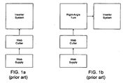
- the input stages of a typical inserter system are depicted in accompanying Figure 1a .
- rolls or stacks of continuous printed documents, called a web are provided at a web supply and fed into a web cutter where the continuous web is cut into individual sheets.
- the input stages of an inserter also include a right-angle turn to allow the individual pages to change their moving direction before they are fed into the inserter, as shown in accompanying Figure 1 b.
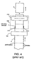
- FIG. 2 of the accompanying drawings illustrates the input stages of an inserter system wherein the continuous web material is provided in a fanfold stack.
- the continuous web material 5 is drawn out of a fanfold stack 2.
- sheets in the continuous web material 5 are linked by perforations so that the web material can be driven continuously by a web driver 100 into a web-cutting module 200.
- the web-cutting module 200 has a cutter 210, usually in a form of a guillotine cutting blade, to cut the web material 5 crosswise into separate sheets 8.
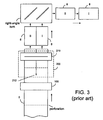
- the web material 5 must be split into two side-by-side portions by a cutting device 212 as shown in accompanying Figure 3 .
- the cutting device 212 may be a stationary knife or a rotating cutting disc. After the web material 5 is split into two side-by-side portions, it is cut crosswise by the cutter 210 into pairs of sheets 8I and 8II. The sheets 8I and 8II move side-by-side toward a right angle turn device so that they can move in tandem into an inserter system (not shown).
- the web-material 5 has a row of sprocket holes on each side of the web material so that the web can be driven by a tractor with pins or a pair of moving belts with sprockets.
- a pair of cutting devices 214 are used to separate the side strips containing the holes from the web material 5 before the web material is cut crosswise by the cutter 210. Additionally, some mechanical devices (not shown) are used to remove the side strips before the web-material is fed into the cutter 210.
- the web material is driven in move-and-pause cycles, wherein the web material is temporarily paused for a short period to allow the cutter to cut the material into cut sheets.
- the web in each cycle, the web must be accelerated and decelerated.
- the acceleration is high, the forces created by the acceleration of the web mass by the driving belt can break the web at a perforation or cause the sprocket holes to tear. Thus, a jam occurs.
- high throughput (20,000+ cycles per hour) is desired
- the acceleration force-induced rip on the sprocket holes is a major limiting factor to the obtainable cycle rate.
- another force is created by aerodynamic effects, due mainly to wind resistance against the motion of the web. The aerodynamics related force may also break the web at a perforation. For this reason, web cutters are usually operated at a cycle rate much lower than the obtainable cycle rate, affecting the throughput of the inserter system.
- a method for controlling a web in a web cutter the web cutter having a cutter module for cutting the web into sheets, a first web driver for moving the web from a web supply and a second web driver downstream from the first web driver for feeding the web to the cutter module, said method comprising: driving the first web driver for achieving a first web velocity having a first velocity profile; driving the second web driver for achieving a second web velocity having a second velocity profile, wherein the second velocity profile is different from the first velocity profile so as to allow a web loop to form between the first web driver and the second web driver, the web loop having a variable loop size between a minimum loop size and a maximum loop size; and controlling at least the first web driver such that, at least in a portion of web cutter operation, the first web velocity increases when the web loop size decreases until the web loop size reaches the minimum loop size, and the first web velocity decreases when the web loop size increases until the web size reaches the maximum loop size, wherein when the web loop size
- a web cutter comprising: a cutter module for cutting a web into sheets; a first web driver for moving the web from a web supply at a first web velocity having a first velocity profile; a second web driver downstream from the first web driver for feeding the web to the cutter module at a second web velocity having a second velocity profile, wherein the second velocity profile is different from the first velocity profile so as to allow a web loop to form between the first web driver and the second web driver, and the web loop has a variable loop size between a minimum loop size and a maximum loop size; and a motion control module for controlling at least the first web driver such that, at least in a portion of web-cutter operation, the first web velocity increases when the web loop size decreases until the web loop size reaches the minimum loop size, and the first web velocity decreases when the web loop size increases until the web loop size reaches the maximum loop size, wherein the motion control module is operable to control at least the first web driver such that when the web loop size reaches the minimum
- the present technique provides a web loop between the web handler axis that draws the web from the stack and the primary axis that feeds the web to a cutter module for cutting.
- a motion control module uses a web control algorithm to control the velocity of the web handler axis as a function of the web loop size using a constant acceleration. The parameters used in this velocity control function are calculated using the system conditions encountered during the worst case scenario. The worst case scenario is assumed when the web loop is at its minimum size; the web handler axis is running at its maximum velocity; and the primary web axis suddenly stops. At this point the web handler motor must decelerate at a rate such that when the axis stops, the web loop is at its maximum size.
- the calculated acceleration is inversely proportional to the maximum web loop size, so that the larger the maximum web loop size is, the lower the acceleration required is, thus reducing the forces applied to the web.
- the desired web handler axis velocity decreases with an increasing web loop size, and when the web loop size reaches its maximum value, the web handler axis velocity is zero. From that point the desired web handler axis velocity will increase as the web loop gets smaller.
- the web handling device is designed to reduce the whipping motion of the web paper immediately upstream of the web cutter and the tension in the web due to the acceleration of the cutter tractor.
- the web cutter uses a driver 100 to move the web material from the web supply and a different driver 150 to feed the web to the cutter.
- the driver 150 is used to feed the web material 5 to the cutter module 200. It is preferred that the web material 5 is temporarily paused for a short period to allow the cutter 220 to cut the material into cut sheets 8. Thus, in each cycle, the web must be accelerated and decelerated.
- the driver 150 is referred to as the web primary axis.
- the driver 100 is used to move the web material from the web supply 2 and is referred to as the web handler axis.
- the main function of the web handler axis 100 is to provide sufficient web material to the web primary axis 150. In order to reduce the whipping motion of the web material as it is moved from the web supply 2, the web handler axis 100 has a different velocity profile.
- the web material driven by the web handler axis 100 is allowed to accumulate between the two axes to form a loop, as shown in Figure 5 .
- the loop will become longer.
- the web handler axis 100 should also be stopped. The maximum amount is shown as the maximum loop in Figure 5 .
- the web handler axis 100 starts again to keep up with the cutter 220 so that the web loop size is never smaller than the minimum loop amount.
- a motion control module 300 is used to control the velocity of the web handler axis 100 as a function of the web loop size using a constant acceleration.
- the parameters used in this velocity control function are calculated using the system conditions encountered during the worst case scenario. Since the algorithm used by the motion control module 300 is designed to handle the worst case conditions, all other possible conditions are handled properly by the algorithm.
- the worst case scenario is encountered when the web loop is at its minimum size; the web handler axis 100 is running at its maximum velocity; and the primary web axis 150 suddenly stops. At this point the web handler motor 100 must decelerate at a rate such that when the web handler axis 100 stops, the web loop is at its maximum size.
- the first step to implement the algorithm is to limit the web handler axis acceleration to a constant value (AWEB) which needs to be calculated based on several system design parameters (see Equation 1).
- the calculated acceleration is inversely proportional to the maximum web loop size, so that the larger the maximum web loop size is, the lower the acceleration required is, thus reducing the forces applied to the web.
- the motion control module calculates the desired web handler axis velocity (VWEB) which decreases with an increasing web loop size (see Equation 2).
- VWEB desired web handler axis velocity
- the desired web handler axis velocity will be zero when the web loop is at its maximum size. From that point the desired web handler axis velocity will increase as the web loop gets smaller.
- the web handler algorithm commands to the web handler axis motor a positive acceleration when the desired web velocity is greater than the actual web velocity and a negative acceleration when the desired web velocity is smaller that the actual web velocity.
- the web handler velocity is such that the web moved by the web handler axis is equal to the amount of web material advanced by the primary axis in each cut cycle.
- the web handler velocity is equal to LDOC/TCYCLE when the actual web loop reaches the minimum loop size.
- the desired web handler velocity (VWEB) is calculated at each sample interval of the web loop, which changes size as a function of the velocity differential between the actual velocities of the primary and web handler axes. In most cases, this desired velocity profile defines a motion path that the actual velocity profile cannot match and will usually lag behind unless the system achieves a steady state. This characteristic is central to this algorithm as it allows the web loop to act as a dampening device between the primary and web handler axes.
- the algorithm is not designed as a direct control loop of the desired web handler velocity versus the actual web handler velocity, but rather as a means to manage the web loop size such that it never exceeds its minimum and maximum boundaries while keeping the web loop inlet acceleration to a minimum.
- An example of the velocity profile of the web handler axis (desired and actual) and that of the primary axis are shown in Figure 6 .
- an anti-hunting algorithm is overlaid on top of the main velocity control algorithm as expressed in Equation 1 and Equation 2.
- the main velocity control algorithm will always command a change in velocity unless the desired and actual velocities are exactly the same. As shown in Figure 6 , the desired and actual velocities do differ from one another. Thus, the main velocity control algorithm will command a change in the velocity. This behavior will cause the desired web handler speed to oscillate around a constant value when the system achieves a steady state. To prevent this oscillation, or hunting, the acceleration is forced to zero when the velocity delta between the desired and actual velocities is within a predefined range.
- the web cutter uses at least two web drivers to move the web.
- One web driver 150 is used to feed the web to a web cutter 220 in move-and-pause cycles.
- Another web driver 100 in the upstream has a constant velocity profile or any waveform with a gentler slope at least in the acceleration period.
- a loop is formed between the web drivers.
- the web material in the loop is sufficient to be advanced past the cutter 220 in each cut cycle.
- a motion control having a software program is used to regulate the web flow by quickly delivering the web when it is needed.
- the acceleration of the web material as it is moved from the web supply by the web handler drive 100 is reduced or eliminated.
- the accumulation of the web material in the loop resembles a web capacitor that is used for storing the web material ahead of time and rapidly discharging it when it is needed. By limiting the force applied to the web, web breakage can be reduced.
Landscapes
- Controlling Rewinding, Feeding, Winding, Or Abnormalities Of Webs (AREA)
- Forming Counted Batches (AREA)
Claims (12)
- Verfahren zum Steuern einer Bahn (5) in einer Bahnschneidvorrichtung, wobei die Bahnschneidvorrichtung ein Schneidmodul (200) zum Schneiden der Bahn (5) in Bögen, einen ersten Bahnantrieb (100) zum Bewegen der Bahn aus einer Bahnzufuhr (2) und einen zweiten Bahnantrieb (150) stromabwärts vom ersten Bahnantrieb (100) zum Zuführen der Bahn zum Schneidmodul (200) aufweist, wobei das Verfahren umfasst:Antreiben des ersten Bahnantriebs (100) zum Erreichen einer ersten Bahngeschwindigkeit (VWEB) mit einem ersten Geschwindigkeitsprofil;Antreiben des zweiten Bahnantriebs (150) zum Erreichen einer zweiten Bahngeschwindigkeit mit einem zweiten Geschwindigkeitsprofil, wobei das zweite Geschwindigkeitsprofil vom ersten Geschwindigkeitsprofil verschieden ist, um die Bildung einer Bahnschleife (XLOOP) zwischen dem ersten Bahnantrieb (100) und dem zweiten Bahnantrieb (150) zu ermöglichen, wobei die Bahnschleife eine veränderliche Schleifengröße zwischen einer kleinsten Schleifengröße und einer größten Schleifengröße aufweist; undderartiges Steuern wenigstens des ersten Bahnantriebs (100), dass wenigstens in einem Abschnitt des Betriebs der Bahnschneidvorrichtung die erste Bahngeschwindigkeit zunimmt, wenn die Bahnschleifengröße abnimmt, bis die Bahnschleifengröße die kleinste Schleifengröße erreicht, und die erste Bahngeschwindigkeit abnimmt, wenn die Bahnschleifengröße zunimmt, bis die Bahngröße die größte Schleifengöße erreicht,wobei, wenn die Bahnschleifengröße die kleinste Schleifengröße erreicht, die erste Bahngeschwindigkeit gleich einem Höchstwert ist, der wenigstens basierend auf dem Durchsatz der Bahnschneidvorrichtung bestimmt wird; undwobei der erste Bahnantrieb (100) im Wesentlichen bei einer konstanten Rate beschleunigt wird, um die erste Bahngeschwindigkeit zu erhöhen, bis die erste Bahngeschwindigkeit den Höchstwert erreicht.
- Verfahren nach Anspruch 1, wobei, wenn die Bahnschleifengröße die größte Schleifengröße erreicht, die erste Bahngeschwindigkeit im Wesentlichen gleich null ist.
- Verfahren nach Anspruch 1, wobei die konstante Rate umgekehrt proportional zu einer Differenz zwischen der größten Schleifengröße und der kleinsten Schleifengröße ist.
- Verfahren nach Anspruch 1 oder 3, wobei die erste Bahngeschwindigkeit proportional zur Quadratwurzel der konstanten Rate ist.
- Verfahren nach einem der vorhergehenden Ansprüche, wobei der Durchsatz basierend auf einer Menge von Bahnmaterial, das durch den zweiten Bahnantrieb (150) in jedem Schneidzyklus vorwärts bewegt wird, geteilt durch eine Zeitdauer zum Vollenden des Schneidzyklus bestimmt wird.
- Verfahren nach einem der vorhergehenden Ansprüche wobei die erste Bahngeschwindigkeit proportional zur Quadratwurzel der Differenz zwischen der größten Schleifengröße und der Bahnschleifehgröße ist.
- Bahnschneidvorrichtung, umfassend:ein Schneidmodul (200) zum Schneiden einer Bahn (5) in Bögen (8);einen ersten Bahnantrieb (100) zum Bewegen der Bahn aus einer Bahnzufuhr mit einer ersten Bahngeschwindigkeit mit einem ersten Geschwindigkeitsprofil;einen zweiten Bahnantrieb (150) stromabwärts vom ersten Bahnantrieb (100) zum Zuführen der Bahn zum Schneidmodul (200) mit einer zweiten Bahngeschwindigkeit mit einem zweiten Geschwindigkeitsprofil, wobei das zweite Geschwindigkeitsprofil vom ersten Geschwindigkeitsprofil verschieden ist, um die Bildung einer Bahnschleife (XLOOP) zwischen dem ersten Bahnantrieb (100) und dem zweiten Bahnantrieb (150) zu ermöglichen, und die Bahnschleife eine veränderliche Schleifengröße zwischen einer kleinsten Schleifengröße und einer größten Schleifengröße aufweist; undein Bewegungssteuerungsmodul (300) zum derartigen Steuern wenigstens des ersten Bahnantriebs (100), dass wenigstens in einem Abschnitt des Betriebs der Bahnschneidvorrichtung die erste Bahngeschwindigkeit zunimmt, wenn die Bahnschleifengröße abnimmt, bis die Bahnschleifengröße die kleinste Schleifengröße erreicht, und die erste Bahngeschwindigkeit abnimmt, wenn die Bahnschleifengröße zunimmt, bis die Bahnschleifengröße die größte Schleifengöße erreicht,wobei das Bewegungssteuerungsmodul (300) so betrieben werden kann, dass es wenigstens den ersten Bahnantrieb (100) derart steuert, dass, wenn die Bahnschleifengröße die kleinste Schleifengröße erreicht, die Bahngeschwindigkeit gleich einem Höchstwert ist, der wenigstens basierend auf einem Durchsatz der Bahnschneidvorrichtung bestimmt wird; undwobei das Bewegungssteuerungsmodul (300) so betrieben werden kann, dass es den ersten Bahnantrieb (100) im Wesentlichen bei einer konstanten Rate beschleunigt, um die erste Bahngeschwindigkeit zu erhöhen, bis die erste Bahngeschwindigkeit den Höchstwert erreicht.
- Bahnschneidvorrichtung nach Anspruch 7, wobei das Bewegungssteuerungsmodul 8300) so betrieben werden kann, dass es wenigstens den ersten Bahnantrieb (100) derart steuert, dass, wenn die Bahnschleifengröße die größte Schleifengröße erreicht, die erste Bahngeschwindigkeit im Wesentlichen gleich null ist.
- Bahnschneidvorrichtung nach Anspruch 7, wobei die konstante Rate umgekehrt proportional zu einer Differenz zwischen der größten Schleifengröße und der kleinsten Schleifengröße ist.
- Bahnschneidvorrichtung nach Anspruch 7 oder 9, wobei die erste Bahngeschwindigkeit proportional zur Quadratwurzel der konstanten Rate ist.
- Bahnschneidvorrichtung nach einem der Ansprüche 7 bis 10, wobei das Bewegungssteuerungsmodul (300) so betrieben werden kann, dass es den Durchsatz basierend auf einer Menge von Bahnmaterial, das durch den zweiten Bahnantrieb (150) in jedem Schneidzyklus vorwärts bewegt wird, geteilt durch eine Zeitdauer zum Vollenden des Schneidzyklus bestimmt.
- Bahnschneidvorrichtung nach einem der Ansprüche 7 bis 11, wobei das Bewegungssteuerungsmodul (300) so ausgelegt ist, dass es die erste Bahngeschwindigkeit so steuert, dass sie proportional zur Quadratwurzel der Differenz zwischen der größten Schleifengröße und der Bahnschleifengröße ist.
Applications Claiming Priority (1)
| Application Number | Priority Date | Filing Date | Title |
|---|---|---|---|
| US11/581,026 US7819393B2 (en) | 2006-10-13 | 2006-10-13 | Web cutter having a web cutter loop |
Publications (3)
| Publication Number | Publication Date |
|---|---|
| EP1911706A2 EP1911706A2 (de) | 2008-04-16 |
| EP1911706A3 EP1911706A3 (de) | 2012-05-02 |
| EP1911706B1 true EP1911706B1 (de) | 2014-01-01 |
Family
ID=38926308
Family Applications (1)
| Application Number | Title | Priority Date | Filing Date |
|---|---|---|---|
| EP07019924.5A Expired - Fee Related EP1911706B1 (de) | 2006-10-13 | 2007-10-11 | Bahnenschneider mit Bahnenschneideschlaufen |
Country Status (2)
| Country | Link |
|---|---|
| US (1) | US7819393B2 (de) |
| EP (1) | EP1911706B1 (de) |
Families Citing this family (7)
| Publication number | Priority date | Publication date | Assignee | Title |
|---|---|---|---|---|
| US20060156876A1 (en) * | 2005-01-19 | 2006-07-20 | Pitney Bowes Incorporated | Motion control system and method for a high speed inserter input |
| US7752948B2 (en) * | 2006-12-01 | 2010-07-13 | Pitney Bowes Inc. | Method and apparatus for enhanced cutter throughput using an exit motion profile |
| US8684489B2 (en) * | 2008-10-08 | 2014-04-01 | Xerox Corporation | System and method for facilitating cutting of media having a phase change ink image |
| US7857442B2 (en) * | 2008-10-20 | 2010-12-28 | Xerox Corporation | Heated folding system for a phase change ink imaging device |
| US8827439B2 (en) | 2012-08-20 | 2014-09-09 | Xerox Corporation | Self-cleaning media perforator |
| JP2014111497A (ja) * | 2012-12-05 | 2014-06-19 | Seiko Epson Corp | 液体吐出装置 |
| US9713936B2 (en) * | 2013-12-19 | 2017-07-25 | Pitney Bowes Inc. | System and method for ensuring cutting accuracy in a mailpiece wrapper |
Family Cites Families (6)
| Publication number | Priority date | Publication date | Assignee | Title |
|---|---|---|---|---|
| US3817067A (en) * | 1972-09-05 | 1974-06-18 | Minster Machine Co | Stock supply system |
| US4464916A (en) * | 1982-05-28 | 1984-08-14 | The Minster Machine Company | Loop follower straightener control in a press installation |
| US4701239A (en) * | 1985-10-15 | 1987-10-20 | Paper Converting Machine Company | Applicator for applying two or more tapes to a moving web |
| US5392977A (en) * | 1993-11-09 | 1995-02-28 | Sankyo Seisakusho Co. | Coil material supply apparatus for an intermittent feed device |
| US5768959A (en) * | 1995-07-31 | 1998-06-23 | Pitney Bowes Inc. | Apparatus for feeding a web |
| DE19648896A1 (de) * | 1996-01-19 | 1997-07-24 | Minster Machine Co | Stanzen-Umführungssteuersystem mit gedämpftem Nachfolger |
-
2006
- 2006-10-13 US US11/581,026 patent/US7819393B2/en active Active
-
2007
- 2007-10-11 EP EP07019924.5A patent/EP1911706B1/de not_active Expired - Fee Related
Also Published As
| Publication number | Publication date |
|---|---|
| US20080106025A1 (en) | 2008-05-08 |
| US7819393B2 (en) | 2010-10-26 |
| EP1911706A2 (de) | 2008-04-16 |
| EP1911706A3 (de) | 2012-05-02 |
Similar Documents
| Publication | Publication Date | Title |
|---|---|---|
| EP1911706B1 (de) | Bahnenschneider mit Bahnenschneideschlaufen | |
| EP1683651B1 (de) | Bewegungskontrolle für die Eingabe eines Hochgeschwindigkeitskuvertierers | |
| US20060075860A1 (en) | System and method for providing sheets to an inserter system using a rotary cutter | |
| US5768959A (en) | Apparatus for feeding a web | |
| US6615105B2 (en) | System and method for adjusting sheet input to an inserter system | |
| EP1101723A2 (de) | Hochgeschwindigkeitsdokument - Verarbeitungsmaschine | |
| US4598901A (en) | Shingling and stacking of conveyed sheet material with pre-shingling control of sheet feed | |
| US6792332B1 (en) | Method for dynamic acceleration in an article transporting system | |
| EP1433733A2 (de) | Fexibles Speicherfördersystem zum Anordnen von gesammelten Dokumenten | |
| US4429602A (en) | Method of crosscutting a web and stacking the cut sheets, and impact-type crosscutter for webs with sheet stacker | |
| EP1577242B1 (de) | System und Verfahren zum Beschicken eines Kuvertiersystem mit Blättern unter Verwendung einer Hochgeschwindigkeitsschneideinrichtung und rechtwinkliger Drehung | |
| US20030089209A1 (en) | Device for cutting paper webs | |
| US9309082B2 (en) | Method and apparatus for enhanced cutter throughput using an exit motion profile | |
| EP1053963B1 (de) | System und Verfahren zum Beschicken von Dokumentsammlungsätzen zu einem Kuvertiersystem | |
| US6607190B1 (en) | Apparatus for providing gap control for a high-speed check feeder | |
| EP2227428B1 (de) | Verfahren und vorrichtung zum transport von papier in einer papierhandhabungsanlage von einem ersten transport an einen zweiten transport | |
| US20090322275A1 (en) | Method and apparatus for improving the position accuracy of a servo motor | |
| EP1798176B1 (de) | Vorrichtung und Verfahren zur Sequenzierung beim Schneiden | |
| US7861628B2 (en) | Method for calibrating a web-cutter having a chip-out cutter module | |
| US20100319505A1 (en) | Device and method for conveying a paper web | |
| US7852021B2 (en) | Method and apparatus for minimizing forces on a web | |
| JPH04182165A (ja) | 用紙搬送装置 | |
| JP2020132379A (ja) | 連続用紙の加工装置 | |
| JP2902264B2 (ja) | シート積上げ装置 | |
| EP1219466A2 (de) | Verfahren zur Bereitstellung eines Kuvertiersystems mit einer variablen Eingabegeschwindigkeit beim Starten |
Legal Events
| Date | Code | Title | Description |
|---|---|---|---|
| PUAI | Public reference made under article 153(3) epc to a published international application that has entered the european phase |
Free format text: ORIGINAL CODE: 0009012 |
|
| AK | Designated contracting states |
Kind code of ref document: A2 Designated state(s): AT BE BG CH CY CZ DE DK EE ES FI FR GB GR HU IE IS IT LI LT LU LV MC MT NL PL PT RO SE SI SK TR |
|
| AX | Request for extension of the european patent |
Extension state: AL BA HR MK RS |
|
| RIN1 | Information on inventor provided before grant (corrected) |
Inventor name: DEPOIS, ARTHUR H. Inventor name: PADROS, XAVIER A. |
|
| PUAL | Search report despatched |
Free format text: ORIGINAL CODE: 0009013 |
|
| AK | Designated contracting states |
Kind code of ref document: A3 Designated state(s): AT BE BG CH CY CZ DE DK EE ES FI FR GB GR HU IE IS IT LI LT LU LV MC MT NL PL PT RO SE SI SK TR |
|
| AX | Request for extension of the european patent |
Extension state: AL BA HR MK RS |
|
| RIC1 | Information provided on ipc code assigned before grant |
Ipc: B65H 23/188 20060101AFI20120326BHEP Ipc: B65H 23/04 20060101ALI20120326BHEP Ipc: B65H 20/24 20060101ALI20120326BHEP |
|
| 17P | Request for examination filed |
Effective date: 20120727 |
|
| RIC1 | Information provided on ipc code assigned before grant |
Ipc: B65H 23/188 20060101AFI20120917BHEP Ipc: B65H 23/04 20060101ALI20120917BHEP Ipc: B65H 20/24 20060101ALI20120917BHEP |
|
| GRAP | Despatch of communication of intention to grant a patent |
Free format text: ORIGINAL CODE: EPIDOSNIGR1 |
|
| AKX | Designation fees paid |
Designated state(s): DE FR GB |
|
| GRAS | Grant fee paid |
Free format text: ORIGINAL CODE: EPIDOSNIGR3 |
|
| RIN1 | Information on inventor provided before grant (corrected) |
Inventor name: DEPOI, ARTHUR H. Inventor name: PADROS, XAVIER A. |
|
| GRAA | (expected) grant |
Free format text: ORIGINAL CODE: 0009210 |
|
| AK | Designated contracting states |
Kind code of ref document: B1 Designated state(s): DE FR GB |
|
| REG | Reference to a national code |
Ref country code: GB Ref legal event code: FG4D |
|
| REG | Reference to a national code |
Ref country code: DE Ref legal event code: R096 Ref document number: 602007034528 Country of ref document: DE Effective date: 20140213 |
|
| REG | Reference to a national code |
Ref country code: DE Ref legal event code: R097 Ref document number: 602007034528 Country of ref document: DE |
|
| PLBE | No opposition filed within time limit |
Free format text: ORIGINAL CODE: 0009261 |
|
| STAA | Information on the status of an ep patent application or granted ep patent |
Free format text: STATUS: NO OPPOSITION FILED WITHIN TIME LIMIT |
|
| 26N | No opposition filed |
Effective date: 20141002 |
|
| REG | Reference to a national code |
Ref country code: DE Ref legal event code: R097 Ref document number: 602007034528 Country of ref document: DE Effective date: 20141002 |
|
| REG | Reference to a national code |
Ref country code: FR Ref legal event code: PLFP Year of fee payment: 9 |
|
| REG | Reference to a national code |
Ref country code: FR Ref legal event code: PLFP Year of fee payment: 10 |
|
| PGFP | Annual fee paid to national office [announced via postgrant information from national office to epo] |
Ref country code: DE Payment date: 20161027 Year of fee payment: 10 Ref country code: GB Payment date: 20161027 Year of fee payment: 10 Ref country code: FR Payment date: 20161025 Year of fee payment: 10 |
|
| REG | Reference to a national code |
Ref country code: DE Ref legal event code: R119 Ref document number: 602007034528 Country of ref document: DE |
|
| GBPC | Gb: european patent ceased through non-payment of renewal fee |
Effective date: 20171011 |
|
| REG | Reference to a national code |
Ref country code: FR Ref legal event code: ST Effective date: 20180629 |
|
| PG25 | Lapsed in a contracting state [announced via postgrant information from national office to epo] |
Ref country code: DE Free format text: LAPSE BECAUSE OF NON-PAYMENT OF DUE FEES Effective date: 20180501 Ref country code: GB Free format text: LAPSE BECAUSE OF NON-PAYMENT OF DUE FEES Effective date: 20171011 |
|
| PG25 | Lapsed in a contracting state [announced via postgrant information from national office to epo] |
Ref country code: FR Free format text: LAPSE BECAUSE OF NON-PAYMENT OF DUE FEES Effective date: 20171031 |